EP1510452A2 - Front suspension for a recreational vehicle - Google Patents
Front suspension for a recreational vehicle Download PDFInfo
- Publication number
- EP1510452A2 EP1510452A2 EP04020042A EP04020042A EP1510452A2 EP 1510452 A2 EP1510452 A2 EP 1510452A2 EP 04020042 A EP04020042 A EP 04020042A EP 04020042 A EP04020042 A EP 04020042A EP 1510452 A2 EP1510452 A2 EP 1510452A2
- Authority
- EP
- European Patent Office
- Prior art keywords
- spindle
- arm
- snowmobile
- chassis
- assembly
- Prior art date
- Legal status (The legal status is an assumption and is not a legal conclusion. Google has not performed a legal analysis and makes no representation as to the accuracy of the status listed.)
- Withdrawn
Links
Images


Classifications
-
- B—PERFORMING OPERATIONS; TRANSPORTING
- B62—LAND VEHICLES FOR TRAVELLING OTHERWISE THAN ON RAILS
- B62K—CYCLES; CYCLE FRAMES; CYCLE STEERING DEVICES; RIDER-OPERATED TERMINAL CONTROLS SPECIALLY ADAPTED FOR CYCLES; CYCLE AXLE SUSPENSIONS; CYCLE SIDE-CARS, FORECARS, OR THE LIKE
- B62K25/00—Axle suspensions
- B62K25/04—Axle suspensions for mounting axles resiliently on cycle frame or fork
-
- B—PERFORMING OPERATIONS; TRANSPORTING
- B62—LAND VEHICLES FOR TRAVELLING OTHERWISE THAN ON RAILS
- B62M—RIDER PROPULSION OF WHEELED VEHICLES OR SLEDGES; POWERED PROPULSION OF SLEDGES OR SINGLE-TRACK CYCLES; TRANSMISSIONS SPECIALLY ADAPTED FOR SUCH VEHICLES
- B62M27/00—Propulsion devices for sledges or the like
- B62M27/02—Propulsion devices for sledges or the like power driven
- B62M2027/026—Snow mobiles characterised by the suspension means
Definitions
- the present invention relates generally to front suspension systems and, in particular, to front suspensions for recreational vehicles such as snowmobiles.
- a typical prior-art snowmobile 10 has a chassis or frame 12 and a motor 14 mounted to the chassis.
- the motor 14 may be either a two-stroke or four-stroke internal combustion engine.
- the motor 14 is connected via a power-transmission system (not shown) to an endless track 30 which is mounted around a rear suspension system 28.
- Handlebars 16 are provided for steering the snowmobile.
- the handlebars 16 are linked via a steering linkage assembly (not shown in Figure 1) to a pair of front skis 18.
- Each front ski 18 is connected to a front suspension system 20.
- the front suspension system 20 includes a swing arm 24 on each side of the snowmobile 10.
- the swing arm 24 is connected to the chassis 12 and to the front suspension system 20.
- the front suspension system 20 also includes a shock absorber assembly 26 for each front ski 18.
- the first type is known as the swing-arm type front suspension.
- the second type is known as the double A-arm front suspension.
- the swing-arm-type suspension system has a swing arm 24.
- the swing arm 24 is pivotally mounted to the chassis 12 of the snowmobile.
- a rear portion of the swing arm 24 has a pivot collar 58 which pivotally connects to a chassis pin 60 which protrudes transversely from a side portion of the chassis.
- a front portion of the swing arm 24 has a tubular, cylindrical spindle holder 56 whose inner diameter is dimensioned to receive a spindle 34.
- a plurality of splines 72 is located at the top of the spindle 34. The splines engage with a star-shaped aperture in a steering arm 74.
- the steering arm 74 is connected via a steering linkage assembly 76 to a steering column (not shown).
- a bracket 62 Also affixed to the cylindrical spindle holder 56 (at the front portion of the swing arm 24) is a bracket 62.
- the bracket 62 fastens to a bottom rod eye of a shock absorber 26 while the top of the shock absorber is fastened to the chassis 12.
- the bracket 62 also has attachment points for an upper suspension arm 64 and a lower suspension arm 66.
- the upper suspension arm 64 and the lower suspension arm 66 are both pivotally connected to the chassis 12 and are also pivotally connected to the bracket 62.
- the upper suspension arm pivots about an axis that is parallel to the centerline 68 of the snowmobile.
- the lower suspension arm pivots about an axis that is parallel to the centerline 68 of the snowmobile.
- the spindle 34 connected to the front ski 18 via a bridge-shaped bracket 36.
- the bridge-shaped bracket 36 is an elongated U-shaped structure with a bottom portion 38 connected to two upwardly extending side portions 40, 42.
- the bottom portion 38 of the bridge-shaped bracket 36 is adapted to fit onto the front ski 18.
- the bridge-shaped bracket 36 has four holes that receive four respective threaded studs 44 that extend upward from a runner 32 that lies underneath the front ski 18. Nuts 46 are tightened onto the threaded studs to fasten the bridge-shaped bracket 36 to the front ski 18.
- Each side portion 40, 42 of the bridge-shaped bracket 36 has a hole 48 through which a spacer 50 may be inserted.
- the spacer 50 is tubular so that a bolt 52 may be inserted inside the spacer.
- the bottom portion of the spindle 34 is welded to a pivoting bracket 31 a which pivots on a bottom bracket 31 b.
- the bottom bracket 31 b is affixed to the front ski 18.
- the pivoting bracket 31 a is pivotally fastened to the bridge-shaped bracket 36 by the bolt 52, spacer 50 and nut 54.
- the swing arm 24 In operation, when the snowmobile 10 encounters a bump, the swing arm 24 will rotate about the chassis pin 60.
- the upper suspension arm 64 and the lower suspension arm 66 act to constrain the motion of the swing arm 24 while the shock absorber assembly 26 acts to dampen the motion by absorbing and dissipating energy.
- the spindle 34 will pivot with respect to the front ski 18 by virtue of the brackets 31 a, 31 b.
- swing-arm suspension system is quite heavy.
- swing arm is oriented at a downward angle relative to the horizontal plane. This downward angle is necessary to provide sufficient ground clearance for the front of the vehicle. Since the swing arm is angled downwardly, the spindle and the front ski must first travel in the forward direction when the front ski encounters a bump. In other words, in order for the front suspension system to compress, the front ski must move forward before it can move upward. Since the vehicle is usually moving forward when it encounters a bump, this forward movement of the front ski augments the impact on the chassis and thus results in rider discomfort.
- a double A-arm front suspension system 20 has an upper A-arm assembly 21 and a lower A-arm assembly 22.
- the upper and lower A-arm assemblies 21, 22 work together to ensure that the front ski 18 and the spindle 34 move vertically when the front ski 18 encounters a bump.
- the front ski 18 and spindle 34 do not have to move forward in order to move upward.
- rider comfort is improved vis-à-vis the swing-arm design.
- the double A-arm design is also heavy.
- the double A-arm design is costly to manufacture because of the number of parts and their complexity.
- the present invention therefore provides a front suspension system for connecting a ground-contacting portion of a recreational vehicle to a chassis of the recreational vehicle, the front suspension system comprising:
- the invention further provides a snowmobile including a chassis, an engine mounted to the chassis, the engine driving an endless track to propel the snowmobile, a rear suspension system disposed within the endless track, and at least one front ski assembly, each front ski assembly being connected to the chassis by a front suspension system, the front suspension system comprising:
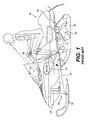
- Figure 1 is a side elevation view of a prior art snowmobile equipped with a swing-arm type front suspension system
- Figure 2 is an exploded isometric perspective view of a swing-arm type front suspension system as found in the prior art
- Figure 3 is an isometric perspective view of a double A-arm front suspension system as found in the prior art
- Figure 4 is a side elevation view of a snowmobile equipped with a front suspension system in accordance with an embodiment of the present invention.
- Figure 5 is an isometric perspective view of an embodiment of a front suspension system in accordance with the present invention.
- Figure 6 is a top plan view of the embodiment of the front suspension system shown in Figure 5;
- Figure 7 is a front elevation view of the embodiment of the front suspension shown in Figure 5;
- Figure 8 is an exploded perspective view of the embodiment of the front suspension shown in Figure 5;
- Figure 9 is a perspective view of an alternative embodiment of the front suspension in accordance with the present invention.
- a front suspension system for a recreational vehicle such as a snowmobile
- a recreational vehicle such as a snowmobile
- the lower A-arm restrains the front ski from moving backward or laterally while the upper arm connects to a top of a spindle assembly to ensure that a spindle remains substantially vertical when the front ski encounters a bump.
- FIGS 4, 5, 6 and 7 illustrate an embodiment of the present invention, namely a front suspension system for a recreational vehicle.
- the recreational vehicle is preferably a snowmobile, although a person skilled in the art will appreciate that the invention may be applicable to other types of recreational vehicles such as all-terrain vehicles.
- FIG. 4 shows a snowmobile 10 with a chassis or frame 12, an engine 14 mounted to the chassis for driving an endless track 30 supported around a rear suspension system 28, a pair of handlebars 16 for steering the snowmobile via a pair of front skis 18, and, for each front ski, a front suspension system 20 in accordance with the present invention.
- the rear suspension system 28 comprises two parallel aluminum slide rails 28a, which generally position and guide the endless drive track 30 and which include idler wheels 30a engaged thereto.
- the slide rails 28a include a slide covering the lower surfaces thereof to reduce contact friction between the slide rails 28a and the endless track 30.
- the slide is preferably made of Ultra High Molecular Weight Polyethylene (UHMWPE).
- the rear suspension system 28 also includes one or more shock absorbers and coil springs. Forward and rear suspension arms of the rear suspension system 28 attach the slide rails 28a to the chassis 12.
- UHMWPE Ultra High Molecular Weight Polyethylene
- the snowmobile 10 comprises an external shell including fairings 11 that enclose the engine 14 to protect it, and which can be decorated to render the snowmobile 10 more aesthetically pleasing.
- the fairings 11 comprise a hood and one or more side panels.
- Two footrests 13, generally comprising part of a tunnel 12a, are also positioned on either side of the seat to accommodate the rider's feet.
- FIG 5 is an isometric perspective view of the front suspension system 20 in accordance with the present invention.
- the front suspension system 20 links the chassis 12 to a ground-contacting portion which, in the case of a snowmobile, is a front ski assembly.
- the front ski assembly has a front ski 18 and an attachment mechanism, such as a bracket 31, for connecting the front ski 18 to a spindle assembly 35.
- the front ski 18 has a pair of holes 48 through which a spacer shaft (see Figure 2) is inserted to affix the spindle assembly 35 to the front ski 18.
- the spindle assembly 35 has a spindle holder 56 which has a tubular portion 56a for housing a spindle 34, as depicted in Figure 5.
- the spindle 34 has splines at its top end so that the splines may engage with a star-shaped aperture in a steering arm 74.
- the steering arm 74 is pivotally connected to a rod 78 which in turn is connected to a steering linkage 76.
- the steering linkage 76 is connected to a steering shaft 77 and to a chassis pivot arm 79.
- the chassis pivot arm 79 is affixed to the chassis 12.
- the steering shaft 77 is connected to the handlebars 16 (not shown).
- the steering shaft 77 rotates. Since the steering linkage 76 is restrained by the chassis pivot arm 79, the steering linkage 76 exerts a force on the steering rod 78 which in turn causes the steering arm 74 to rotate about the longitudinal axis of the spindle 34. Since the spindle 34 is splined to the steering arm 74, the spindle rotates as well, thereby causing the front ski 18 to turn.
- the spindle assembly 35 of the front suspension system 20 has a single A-arm assembly 22 and a lone (single) upper suspension arm 23.
- the A-arm assembly 22 has a first member 22a and a second member 22b.
- the first and second members 22a, 22b of the A-arm assembly 22 are preferably of the same diameter and are made of steel or an alloy having a high elastic modulus.
- the first member 22a is pivotally connected at a proximal end to the chassis 12 and is pivotally connected at a distal end to the spindle assembly 35.
- the second member 22b is pivotally connected at a proximal end to the chassis 12 and is pivotally connected at a distal end to the spindle assembly 35.
- proximal and distal refer to the chassis.
- proximal end is the end that is closer to the chassis whereas the distal end is the end that is farther away from the chassis.
- the upper suspension arm 23 is pivotally connected to the chassis 12 at a chassis pivot 23a.
- the upper suspension arm 23 is preferably connected via a ball joint 23b to a top of the spindle 34.
- the distal end of the upper suspension arm 23 may be connected via the ball joint 23b to the top of the spindle assembly 35.
- the upper suspension arm 23 is preferably a single rod of a smaller diameter than the first and second members 22a, 22b.
- the rod may be tubular or constructed from a lighter material having a lesser elastic modulus than that of the first and second members 22a, 22b of the A-arm assembly 22.
- the rod 23 need not be as strong as the first and second members of the A-arm assembly 22 because the loads exerted on the rod 23 are less than those exerted on the first and second members 22a, 22b of the A-arm assembly 22. Since most of the loads are lateral and front-to-back, a smaller and lighter upper suspension arm 23 is adequate to hold the spindle assembly 35 in a vertical orientation. The single A-arm assembly 22 is able to safely withstand the lateral and front-to-back loads exerted on the front suspension system 20.
- the upper suspension arm 23 is preferably a rod of smaller diameter than the first and second members 22a, 22b of the A-arm assembly 22, the upper suspension arm 23 may also be of the same diameter and material as the first and second members 22a, 22b of the A-arm assembly 22.
- a shock/spring assembly 26 (having a shock absorber and a coil spring) is pivotally attached at a bottom end to the first member 22a of the A-arm assembly 22 while a top end of the shock/spring assembly 26 is pivotally attached to the chassis 12.
- the shock/spring assembly 26 may be pivotally attached to the spindle assembly 35.
- the front suspension system 20 has a lower A-arm assembly 22 (including a first member 22a and a second member 22b) and an upper suspension arm (or radius rod) 23.
- the upper suspension arm 23 has a proximal end 23a for pivotal connection to the chassis and a distal end 23b which connects to a ball joint 23c.
- a spindle 34 has a base bracket 31 for connection to a front ski.
- the spindle 34 has splines 72 at a top end. Affixed to the top surface of the spindle 34 is the ball joint 23c.
- a spindle holder 56 having a tubular sleeve 56a houses the spindle 34 and has a pivotal attachment point 56c for the lower A-arm assembly 22.
- a star-shaped aperture in the steering arm 74 meshes with the splines 72.
- the steering arm 74 connects at an offset point to a steering rod 78.
- the front suspension system uses a different type of spindle holder 56.
- the spindle holder 56 has its ball joint 23c affixed not to the top of the spindle 34 as in Figure 8 but rather to an extension surface 56b.
- the extension surface 56b is preferably welded to the tubular sleeve 56a.
- the ball joint 23c is oriented upwardly to facilitate connection to the distal end 23b of the upper suspension arm 23.
- This alternative embodiment may be used where there are vertical spacing restrictions in the front suspension.
- the front suspension system 20 is light, easy to manufacture and inexpensive.
- the simple yet versatile design of the front suspension system 20 permits a person skilled in the art to modify the position and orientation of the A-arm assembly 22 to achieve different ride dynamics.
- the A-arm assembly 22 can be attached to the chassis 12 at a different angle than what is shown in Figure 7 so as to permit the front ski 18 to move back and forth in the travel direction when a bump is encountered. Lateral movement of each front ski 18 (known as "scrub”) may also be adjusted by varying the lengths of the upper suspension arm 23 and the first and second A-arm members 22a, 22b.
- scrub may also be adjusted by varying the lengths of the upper suspension arm 23 and the first and second A-arm members 22a, 22b.
Landscapes
- Engineering & Computer Science (AREA)
- Mechanical Engineering (AREA)
- Chemical & Material Sciences (AREA)
- Combustion & Propulsion (AREA)
- Transportation (AREA)
- Vehicle Body Suspensions (AREA)
Abstract
Description
- This application claims the benefit of priority to U.S.
Provisional Application 60/497,322 filed on August 25, 2003, the contents of which are incorporated herein by reference. - The present invention relates generally to front suspension systems and, in particular, to front suspensions for recreational vehicles such as snowmobiles.
- As illustrated in Figure 1, a typical prior-
art snowmobile 10 has a chassis orframe 12 and amotor 14 mounted to the chassis. Themotor 14 may be either a two-stroke or four-stroke internal combustion engine. Themotor 14 is connected via a power-transmission system (not shown) to anendless track 30 which is mounted around arear suspension system 28.Handlebars 16 are provided for steering the snowmobile. Thehandlebars 16 are linked via a steering linkage assembly (not shown in Figure 1) to a pair offront skis 18. Eachfront ski 18 is connected to afront suspension system 20. Thefront suspension system 20 includes aswing arm 24 on each side of thesnowmobile 10. Theswing arm 24 is connected to thechassis 12 and to thefront suspension system 20. Thefront suspension system 20 also includes ashock absorber assembly 26 for eachfront ski 18. - There are two types of front suspension systems that are commonly used on snowmobiles. The first type is known as the swing-arm type front suspension. The second type is known as the double A-arm front suspension.
- As illustrated in Figure 2, the swing-arm-type suspension system has a
swing arm 24. Theswing arm 24 is pivotally mounted to thechassis 12 of the snowmobile. A rear portion of theswing arm 24 has apivot collar 58 which pivotally connects to achassis pin 60 which protrudes transversely from a side portion of the chassis. A front portion of theswing arm 24 has a tubular,cylindrical spindle holder 56 whose inner diameter is dimensioned to receive aspindle 34. A plurality ofsplines 72 is located at the top of thespindle 34. The splines engage with a star-shaped aperture in asteering arm 74. Thesteering arm 74 is connected via asteering linkage assembly 76 to a steering column (not shown). Also affixed to the cylindrical spindle holder 56 (at the front portion of the swing arm 24) is abracket 62. Thebracket 62 fastens to a bottom rod eye of a shock absorber 26 while the top of the shock absorber is fastened to thechassis 12. Thebracket 62 also has attachment points for anupper suspension arm 64 and alower suspension arm 66. Theupper suspension arm 64 and thelower suspension arm 66 are both pivotally connected to thechassis 12 and are also pivotally connected to thebracket 62. The upper suspension arm pivots about an axis that is parallel to thecenterline 68 of the snowmobile. Likewise, the lower suspension arm pivots about an axis that is parallel to thecenterline 68 of the snowmobile. - Still referring to Figure 2, the
spindle 34 connected to thefront ski 18 via a bridge-shaped bracket 36. The bridge-shaped bracket 36 is an elongated U-shaped structure with abottom portion 38 connected to two upwardly extendingside portions bottom portion 38 of the bridge-shaped bracket 36 is adapted to fit onto thefront ski 18. The bridge-shaped bracket 36 has four holes that receive four respective threadedstuds 44 that extend upward from arunner 32 that lies underneath thefront ski 18.Nuts 46 are tightened onto the threaded studs to fasten the bridge-shaped bracket 36 to thefront ski 18. Eachside portion shaped bracket 36 has ahole 48 through which aspacer 50 may be inserted. There are corresponding holes on the sides of thepivoting bracket 31a. Thespacer 50 is tubular so that abolt 52 may be inserted inside the spacer. The bottom portion of thespindle 34 is welded to a pivotingbracket 31 a which pivots on abottom bracket 31 b. Thebottom bracket 31 b is affixed to thefront ski 18. Thepivoting bracket 31 a is pivotally fastened to the bridge-shapedbracket 36 by thebolt 52,spacer 50 andnut 54. When thespacer 50 is inserted in theholes 48 and through the corresponding holes of thepivoting bracket 31 a, thespacer 50 restrains thepivoting bracket 31 a. The pivoting bracket and thespindle 34 may then rotate in a semicircular recess located in thebottom bracket 31 b. This permits thespindle 34 to pivot with respect to thefront ski 18. - In operation, when the
snowmobile 10 encounters a bump, theswing arm 24 will rotate about thechassis pin 60. Theupper suspension arm 64 and thelower suspension arm 66 act to constrain the motion of theswing arm 24 while theshock absorber assembly 26 acts to dampen the motion by absorbing and dissipating energy. As the swing arm moves, thespindle 34 will pivot with respect to thefront ski 18 by virtue of thebrackets - One shortcoming of the swing-arm suspension system is that it is quite heavy. Another shortcoming of the swing-arm suspension system is that the swing arm is oriented at a downward angle relative to the horizontal plane. This downward angle is necessary to provide sufficient ground clearance for the front of the vehicle. Since the swing arm is angled downwardly, the spindle and the front ski must first travel in the forward direction when the front ski encounters a bump. In other words, in order for the front suspension system to compress, the front ski must move forward before it can move upward. Since the vehicle is usually moving forward when it encounters a bump, this forward movement of the front ski augments the impact on the chassis and thus results in rider discomfort.
- As noted above, a second type of front suspension system that is well known in the art is the double A-arm suspension. As illustrated in Figure 3, a double A-arm
front suspension system 20 has anupper A-arm assembly 21 and alower A-arm assembly 22. The upper and lower A-arm assemblies 21, 22 work together to ensure that thefront ski 18 and thespindle 34 move vertically when thefront ski 18 encounters a bump. Unlike the swing-arm suspension, thefront ski 18 andspindle 34 do not have to move forward in order to move upward. Thus, rider comfort is improved vis-à-vis the swing-arm design. However, the double A-arm design is also heavy. Furthermore, the double A-arm design is costly to manufacture because of the number of parts and their complexity. - There is therefore a need for an improved front suspension system that is lighter than the prior art suspensions and that is less expensive and easier to construct.
- It is therefore an object of the present invention to provide an improved front suspension system that is lighter, less expensive and easier to construct than the suspension systems known in the art.
- The present invention therefore provides a front suspension system for connecting a ground-contacting portion of a recreational vehicle to a chassis of the recreational vehicle, the front suspension system comprising:
- an A-arm assembly having:
- a first member pivotally connected at a proximal end to the chassis and at a distal end to the ground-contacting portion; and
- a second member pivotally connected at a proximal end to the chassis and at a distal end to the ground-contacting portion; and
- a lone suspension arm disposed above the A-arm assembly, the suspension arm being pivotally connected at a proximal end to the chassis and at a distal end to the ground-contacting portion.
- The invention further provides a snowmobile including a chassis, an engine mounted to the chassis, the engine driving an endless track to propel the snowmobile, a rear suspension system disposed within the endless track, and at least one front ski assembly, each front ski assembly being connected to the chassis by a front suspension system, the front suspension system comprising:
- an A-arm assembly having:
- a first member pivotally connected at a proximal end to the chassis and at a distal end to the front ski assembly; and
- a second member pivotally connected at a proximal end to the chassis and at a distal end to the front ski assembly; and
- a lone suspension arm disposed above the A-arm assembly, the suspension arm being pivotally connected at a proximal end to the chassis and at a distal end to the front ski assembly.
- Further features and advantages of the present invention will become apparent from the following detailed description, taken in combination with the appended drawings, in which:
- Figure 1 is a side elevation view of a prior art snowmobile equipped with a swing-arm type front suspension system;
- Figure 2 is an exploded isometric perspective view of a swing-arm type front suspension system as found in the prior art;
- Figure 3 is an isometric perspective view of a double A-arm front suspension system as found in the prior art;
- Figure 4 is a side elevation view of a snowmobile equipped with a front suspension system in accordance with an embodiment of the present invention.
- Figure 5 is an isometric perspective view of an embodiment of a front suspension system in accordance with the present invention;
- Figure 6 is a top plan view of the embodiment of the front suspension system shown in Figure 5;
- Figure 7 is a front elevation view of the embodiment of the front suspension shown in Figure 5;
- Figure 8 is an exploded perspective view of the embodiment of the front suspension shown in Figure 5; and
- Figure 9 is a perspective view of an alternative embodiment of the front suspension in accordance with the present invention.
- It will be noted that throughout the appended drawings, like features are identified by like reference numerals.
- In general, and as will be elaborated below, a front suspension system for a recreational vehicle such as a snowmobile has a lower A-arm assembly and an upper suspension arm for connecting each front ski to a chassis of the recreational vehicle. The lower A-arm restrains the front ski from moving backward or laterally while the upper arm connects to a top of a spindle assembly to ensure that a spindle remains substantially vertical when the front ski encounters a bump.
- Figures 4, 5, 6 and 7 illustrate an embodiment of the present invention, namely a front suspension system for a recreational vehicle.
- As depicted in Figure 4, the recreational vehicle is preferably a snowmobile, although a person skilled in the art will appreciate that the invention may be applicable to other types of recreational vehicles such as all-terrain vehicles.
- Consistent with Figure 1, Figure 4 shows a
snowmobile 10 with a chassis orframe 12, anengine 14 mounted to the chassis for driving anendless track 30 supported around arear suspension system 28, a pair ofhandlebars 16 for steering the snowmobile via a pair offront skis 18, and, for each front ski, afront suspension system 20 in accordance with the present invention. Therear suspension system 28 comprises two parallelaluminum slide rails 28a, which generally position and guide theendless drive track 30 and which includeidler wheels 30a engaged thereto. The slide rails 28a include a slide covering the lower surfaces thereof to reduce contact friction between the slide rails 28a and theendless track 30. The slide is preferably made of Ultra High Molecular Weight Polyethylene (UHMWPE). Therear suspension system 28 also includes one or more shock absorbers and coil springs. Forward and rear suspension arms of therear suspension system 28 attach the slide rails 28a to thechassis 12. - At the front of the
chassis 12, thesnowmobile 10 comprises an externalshell including fairings 11 that enclose theengine 14 to protect it, and which can be decorated to render thesnowmobile 10 more aesthetically pleasing. Typically, thefairings 11 comprise a hood and one or more side panels. Awindshield 15, which may be connected either to thefairings 11 or directly to thehandlebars 16, acts as a wind deflector to lessen the force of the air on the rider when the snowmobile is moving. Twofootrests 13, generally comprising part of atunnel 12a, are also positioned on either side of the seat to accommodate the rider's feet. - Figure 5 is an isometric perspective view of the
front suspension system 20 in accordance with the present invention. Thefront suspension system 20 links thechassis 12 to a ground-contacting portion which, in the case of a snowmobile, is a front ski assembly. The front ski assembly has afront ski 18 and an attachment mechanism, such as abracket 31, for connecting thefront ski 18 to aspindle assembly 35. Thefront ski 18 has a pair ofholes 48 through which a spacer shaft (see Figure 2) is inserted to affix thespindle assembly 35 to thefront ski 18. - The
spindle assembly 35 has aspindle holder 56 which has atubular portion 56a for housing aspindle 34, as depicted in Figure 5. Thespindle 34 has splines at its top end so that the splines may engage with a star-shaped aperture in asteering arm 74. Thesteering arm 74 is pivotally connected to arod 78 which in turn is connected to asteering linkage 76. Thesteering linkage 76 is connected to asteering shaft 77 and to achassis pivot arm 79. Thechassis pivot arm 79 is affixed to thechassis 12. The steeringshaft 77 is connected to the handlebars 16 (not shown). - When a driver of the
snowmobile 10 turns thehandlebars 16, the steeringshaft 77 rotates. Since thesteering linkage 76 is restrained by thechassis pivot arm 79, thesteering linkage 76 exerts a force on the steeringrod 78 which in turn causes thesteering arm 74 to rotate about the longitudinal axis of thespindle 34. Since thespindle 34 is splined to thesteering arm 74, the spindle rotates as well, thereby causing thefront ski 18 to turn. - As shown in Figures 5, 6 and 7, the
spindle assembly 35 of thefront suspension system 20 has a singleA-arm assembly 22 and a lone (single)upper suspension arm 23. - The
A-arm assembly 22 has afirst member 22a and asecond member 22b. The first andsecond members A-arm assembly 22 are preferably of the same diameter and are made of steel or an alloy having a high elastic modulus. Thefirst member 22a is pivotally connected at a proximal end to thechassis 12 and is pivotally connected at a distal end to thespindle assembly 35. Thesecond member 22b is pivotally connected at a proximal end to thechassis 12 and is pivotally connected at a distal end to thespindle assembly 35. - Throughout this specification, the terms "proximal" and "distal" refer to the chassis. Thus, the proximal end is the end that is closer to the chassis whereas the distal end is the end that is farther away from the chassis.
- At a proximal end, the
upper suspension arm 23 is pivotally connected to thechassis 12 at achassis pivot 23a. At a distal end, theupper suspension arm 23 is preferably connected via a ball joint 23b to a top of thespindle 34. Alternatively, the distal end of theupper suspension arm 23 may be connected via the ball joint 23b to the top of thespindle assembly 35. Theupper suspension arm 23 is preferably a single rod of a smaller diameter than the first andsecond members second members A-arm assembly 22. Therod 23 need not be as strong as the first and second members of theA-arm assembly 22 because the loads exerted on therod 23 are less than those exerted on the first andsecond members A-arm assembly 22. Since most of the loads are lateral and front-to-back, a smaller and lighterupper suspension arm 23 is adequate to hold thespindle assembly 35 in a vertical orientation. The singleA-arm assembly 22 is able to safely withstand the lateral and front-to-back loads exerted on thefront suspension system 20. Although theupper suspension arm 23 is preferably a rod of smaller diameter than the first andsecond members A-arm assembly 22, theupper suspension arm 23 may also be of the same diameter and material as the first andsecond members A-arm assembly 22. - As shown in Figures 5, 6, and 7, a shock/spring assembly 26 (having a shock absorber and a coil spring) is pivotally attached at a bottom end to the
first member 22a of theA-arm assembly 22 while a top end of the shock/spring assembly 26 is pivotally attached to thechassis 12. Alternatively, the shock/spring assembly 26 may be pivotally attached to thespindle assembly 35. - The design of the
front suspension system 20 is further described with reference to Figure 8. In this exploded perspective view, thefront suspension system 20 has a lower A-arm assembly 22 (including afirst member 22a and asecond member 22b) and an upper suspension arm (or radius rod) 23. Theupper suspension arm 23 has aproximal end 23a for pivotal connection to the chassis and adistal end 23b which connects to a ball joint 23c. Aspindle 34 has abase bracket 31 for connection to a front ski. Thespindle 34 hassplines 72 at a top end. Affixed to the top surface of thespindle 34 is the ball joint 23c. Aspindle holder 56 having atubular sleeve 56a houses thespindle 34 and has apivotal attachment point 56c for the lowerA-arm assembly 22. A star-shaped aperture in thesteering arm 74 meshes with thesplines 72. Thesteering arm 74 connects at an offset point to asteering rod 78. - In an alternative embodiment, depicted in Figure 9, the front suspension system uses a different type of
spindle holder 56. Thespindle holder 56 has its ball joint 23c affixed not to the top of thespindle 34 as in Figure 8 but rather to anextension surface 56b. Theextension surface 56b is preferably welded to thetubular sleeve 56a. The ball joint 23c is oriented upwardly to facilitate connection to thedistal end 23b of theupper suspension arm 23. This alternative embodiment may be used where there are vertical spacing restrictions in the front suspension. - With regard to both of the foregoing embodiments, a person skilled in the art will appreciate that a pivot joint may be used in lieu of the illustrated ball joint 23c.
- Because the
upper suspension arm 23 is but a single rod of smaller diameter than the A-arm members, thefront suspension system 20 is light, easy to manufacture and inexpensive. - Furthermore, the simple yet versatile design of the
front suspension system 20 permits a person skilled in the art to modify the position and orientation of theA-arm assembly 22 to achieve different ride dynamics. TheA-arm assembly 22 can be attached to thechassis 12 at a different angle than what is shown in Figure 7 so as to permit thefront ski 18 to move back and forth in the travel direction when a bump is encountered. Lateral movement of each front ski 18 (known as "scrub") may also be adjusted by varying the lengths of theupper suspension arm 23 and the first and secondA-arm members - The embodiments of the invention described above are therefore intended to be exemplary only. The scope of the invention is intended to be limited solely by the scope of the appended claims.
Claims (8)
- A snowmobile comprising:a chassis including a tunnel;an engine disposed on the chassis;a drive track disposed below and supported by the tunnel and operatively connected to the engine for propulsion of the snowmobile;left and right suspensions, each suspension comprising:a spindle holder;a spindle rotatable about a substantially vertical axis within the spindle holder, the spindle having a top end and a bottom end;a lower A-arm having a first member and a second member, each of the members pivotally connected to the chassis at their proximal ends and each of the members pivotally connected to the spindle holder at their distal ends;an upper suspension arm pivotally connected at its proximal end to the chassis and at a distal end to the top end of the spindle;two skis, one ski connected to the bottom end of the spindle of each of the front suspensions.
- The snowmobile as claimed in claim 1, wherein the spindle holder is a tubular sleeve, the top end and the bottom end of the spindle extend beyond the tubular sleeve.
- The snowmobile as claimed in claim 1, wherein the upper suspension arm is a single rod.
- The snowmobile as claimed in claim 2, further comprising a ball joint connected to one of the upper suspension arm and the top portion of the spindle, the pivotal connection between the upper suspension arm and the top portion of the spindle being through the ball joint.
- The snowmobile as claimed in claim 4, further comprising a shock absorber, the shock absorber attached at a first end to the chassis and at a second end to the A-arm.
- The snowmobile as claimed in claim 4, wherein the top portion of the spindle further comprises splines.
- The snowmobile as claimed in claim 6, wherein the splines are located on a portion of the top end of the spindle extending beyond the tubular sleeve below the ball joint and wherein the snowmobile further comprises a steering linkage coupled with the splines in order to rotate the spindle.
- The snowmobile as claimed in claim 7, wherein the bottom end of the spindle further comprises a bracket connecting the bottom end of the spindle to the ski.
Applications Claiming Priority (2)
| Application Number | Priority Date | Filing Date | Title |
|---|---|---|---|
| US49732203P | 2003-08-25 | 2003-08-25 | |
| US497322P | 2003-08-25 |
Publications (2)
| Publication Number | Publication Date |
|---|---|
| EP1510452A2 true EP1510452A2 (en) | 2005-03-02 |
| EP1510452A3 EP1510452A3 (en) | 2006-06-07 |
Family
ID=34103033
Family Applications (1)
| Application Number | Title | Priority Date | Filing Date |
|---|---|---|---|
| EP04020042A Withdrawn EP1510452A3 (en) | 2003-08-25 | 2004-08-24 | Front suspension for a recreational vehicle |
Country Status (3)
| Country | Link |
|---|---|
| US (2) | US6976550B2 (en) |
| EP (1) | EP1510452A3 (en) |
| CA (1) | CA2478003A1 (en) |
Cited By (1)
| Publication number | Priority date | Publication date | Assignee | Title |
|---|---|---|---|---|
| WO2015035013A3 (en) * | 2013-09-04 | 2015-04-30 | Polaris Industries Inc. | Side-by-side vehicle |
Families Citing this family (18)
| Publication number | Priority date | Publication date | Assignee | Title |
|---|---|---|---|---|
| CA2483670C (en) * | 2004-10-01 | 2011-12-06 | Peter Nietlispach | Improvements to snowmobile steering and suspensions for improved performance in turns |
| CA2591755C (en) * | 2004-12-21 | 2009-05-26 | Bombardier Recreational Products Inc. | Endless belt drive for vehicle |
| US20060178697A1 (en) * | 2005-02-04 | 2006-08-10 | Carr-Brendel Victoria E | Vaso-occlusive devices including non-biodegradable biomaterials |
| US7374188B2 (en) * | 2005-02-18 | 2008-05-20 | Artic Cat Inc. | Vehicle tracking control system |
| US20080029324A1 (en) * | 2006-01-23 | 2008-02-07 | Thorr Action Sports, Inc. | Snow vehicle |
| US7578366B2 (en) * | 2006-02-02 | 2009-08-25 | Yamaha Hatsudoki Kabushiki Kaisha | Snowmobile and stopper mechanism for snowmobile |
| US20080067774A1 (en) * | 2006-09-15 | 2008-03-20 | Textron Inc. | Double wishbone front suspension |
| US8690182B2 (en) | 2007-03-12 | 2014-04-08 | Robert A. Wrightman | Strut for snowmobile |
| US20110089649A1 (en) * | 2009-10-16 | 2011-04-21 | Wrightman Robert A | Strut for ski assembly |
| US8360449B2 (en) * | 2009-11-16 | 2013-01-29 | Great Lakes Sound & Vibration, Inc. | Suspension assemblies and systems for land vehicles |
| US8657054B2 (en) | 2010-01-29 | 2014-02-25 | Bombardier Recreational Products Inc. | Front suspension and ski assembly for a snowmobile |
| US9090313B2 (en) | 2010-09-30 | 2015-07-28 | Bombardier Recreational Products Inc. | Snowmobile having a front suspension assembly with at least one protrusion |
| RU2595999C2 (en) * | 2011-07-25 | 2016-08-27 | Бомбардир Рекриейшнл Продактс Инк. | Snowmobile suspension |
| CN103213648A (en) * | 2013-04-18 | 2013-07-24 | 东北大学 | Snow bike |
| WO2014191941A1 (en) | 2013-05-31 | 2014-12-04 | Bombardier Recreational Products Inc. | Snowmobile suspension |
| US11220283B2 (en) | 2017-08-28 | 2022-01-11 | Surface Pro Design Inc. | Front ski suspension system for a snowmobile and method for installing the same |
| FI129950B (en) | 2021-11-08 | 2022-11-30 | Aurora Powertrains Oy | Front suspension for an electric snowmobile |
| USD1014345S1 (en) * | 2022-02-15 | 2024-02-13 | Arctic Cat Inc. | Recreational vehicle spindle |
Citations (4)
| Publication number | Priority date | Publication date | Assignee | Title |
|---|---|---|---|---|
| US4591184A (en) * | 1983-08-30 | 1986-05-27 | Bayerische Motoren Werke Ag | Wheel suspension for steerable front wheels of motor vehicles |
| US5503242A (en) * | 1994-09-27 | 1996-04-02 | Jeffers; Terry E. | Propeller driven snow buggy |
| US20020175013A1 (en) * | 1998-12-31 | 2002-11-28 | Formula Fast Racing | Snowmobile construction |
| US20030019676A1 (en) * | 2001-07-24 | 2003-01-30 | Bertrand Mallette | Spindle for convertable ski stance |
Family Cites Families (11)
| Publication number | Priority date | Publication date | Assignee | Title |
|---|---|---|---|---|
| FR2079831A5 (en) * | 1970-02-13 | 1971-11-12 | Bourcier De Carbon Ch | |
| US5033572A (en) | 1990-03-12 | 1991-07-23 | Arctco, Inc. | Drive system for a snowmobile |
| US5038882A (en) | 1990-03-12 | 1991-08-13 | Arctco, Inc. | Snowmobile spindle arrangement |
| JPH09193878A (en) * | 1996-01-22 | 1997-07-29 | Yamaha Motor Co Ltd | Cooling device of snow vehicle |
| US6009966A (en) | 1997-10-09 | 2000-01-04 | Polaris Industries Inc. | Snowmobile front suspension system |
| US6199649B1 (en) * | 1998-05-26 | 2001-03-13 | Arctek Inc. | Snowmobile steering and ski suspension |
| US6234264B1 (en) * | 1998-11-24 | 2001-05-22 | A & D Boivin Design | Snowmobile suspension system |
| US6655487B2 (en) | 1998-12-23 | 2003-12-02 | Bombardier Inc. | Front suspension with three ball joints for a vehicle |
| US6311798B1 (en) * | 1999-11-19 | 2001-11-06 | Polaris Industries Inc. | Snowmobile with adjustable width front suspension |
| US6474662B1 (en) * | 2001-05-04 | 2002-11-05 | Dale D. Cormican | Snowmobile ski suspension system |
| US6942050B1 (en) | 2004-04-28 | 2005-09-13 | Polaris Industries Inc. | Snowmobile front suspension system and method |
-
2004
- 2004-08-18 CA CA002478003A patent/CA2478003A1/en not_active Abandoned
- 2004-08-19 US US10/921,093 patent/US6976550B2/en not_active Expired - Lifetime
- 2004-08-24 EP EP04020042A patent/EP1510452A3/en not_active Withdrawn
-
2005
- 2005-12-07 US US11/295,512 patent/US7198126B2/en not_active Expired - Lifetime
Patent Citations (4)
| Publication number | Priority date | Publication date | Assignee | Title |
|---|---|---|---|---|
| US4591184A (en) * | 1983-08-30 | 1986-05-27 | Bayerische Motoren Werke Ag | Wheel suspension for steerable front wheels of motor vehicles |
| US5503242A (en) * | 1994-09-27 | 1996-04-02 | Jeffers; Terry E. | Propeller driven snow buggy |
| US20020175013A1 (en) * | 1998-12-31 | 2002-11-28 | Formula Fast Racing | Snowmobile construction |
| US20030019676A1 (en) * | 2001-07-24 | 2003-01-30 | Bertrand Mallette | Spindle for convertable ski stance |
Cited By (7)
| Publication number | Priority date | Publication date | Assignee | Title |
|---|---|---|---|---|
| WO2015035013A3 (en) * | 2013-09-04 | 2015-04-30 | Polaris Industries Inc. | Side-by-side vehicle |
| AU2014315278B2 (en) * | 2013-09-04 | 2017-08-31 | Polaris Industries Inc. | Side-by-side vehicle |
| US10369861B2 (en) | 2013-09-04 | 2019-08-06 | Polaris Industries Inc. | Side-by-side vehicle |
| US10737547B2 (en) | 2013-09-04 | 2020-08-11 | Polaris Industries Inc. | Side-by-side vehicle |
| US11091003B2 (en) | 2013-09-04 | 2021-08-17 | Polaris Industries Inc. | Side-by-side vehicle |
| US11660927B2 (en) | 2013-09-04 | 2023-05-30 | Polaris Industries Inc. | Side-by-side vehicle |
| US11993124B2 (en) | 2013-09-04 | 2024-05-28 | Polaris Industries Inc. | Side-by-side vehicle |
Also Published As
| Publication number | Publication date |
|---|---|
| US7198126B2 (en) | 2007-04-03 |
| US20060081407A1 (en) | 2006-04-20 |
| US20050045397A1 (en) | 2005-03-03 |
| US6976550B2 (en) | 2005-12-20 |
| EP1510452A3 (en) | 2006-06-07 |
| CA2478003A1 (en) | 2005-02-25 |
Similar Documents
| Publication | Publication Date | Title |
|---|---|---|
| US7198126B2 (en) | Front suspension for recreational vehicle | |
| US6390219B1 (en) | Rear suspension system for a snowmobile | |
| US6631778B2 (en) | Shock linkage assembly for a snowmobile suspension system | |
| US8453779B2 (en) | Snowmobile frame | |
| US7070012B2 (en) | Snowmobile suspension | |
| US20200216134A1 (en) | Vehicle having a suspension assembly including a swing arm | |
| US9162731B2 (en) | Snowmobile | |
| RU2595999C2 (en) | Snowmobile suspension | |
| US10065708B2 (en) | Snowmobile suspension | |
| CA3207355A1 (en) | Snowmobile with cvt clutch arrangement | |
| US11890911B2 (en) | Rear suspension assembly and method of controlling a rear suspension assembly | |
| US7131511B2 (en) | Motorcycle with a rear suspension having a pull shock track system | |
| US6581716B1 (en) | All terrain vehicle with rear-facing rear arm bracket | |
| US20020163158A1 (en) | Suspension system for a bicycle trailer | |
| CA2373337A1 (en) | Snowmobile slide rail system | |
| US4592441A (en) | Three-wheeled motor vehicle with pivotable frame | |
| CA3061397C (en) | Tracked vehicle | |
| US20070169978A1 (en) | Suspension apparatus for a wheeled vehicle utilizing offset frame with torsion shock absorber | |
| US11518453B2 (en) | Rear suspension assembly for a snowmobile | |
| US11364960B2 (en) | Vehicle with an actuator for adjusting a suspension assembly | |
| US11701936B1 (en) | Vehicle with support assembly for suspension arm | |
| CA2523999A1 (en) | Snowmobile with beveled tunnel | |
| CA3153594A1 (en) | Vehicle with support assembly for suspension arm | |
| CA2441643A1 (en) | Snowmobile suspension geometry | |
| JP3122610B2 (en) | Bicycle shock absorber frame |
Legal Events
| Date | Code | Title | Description |
|---|---|---|---|
| PUAI | Public reference made under article 153(3) epc to a published international application that has entered the european phase |
Free format text: ORIGINAL CODE: 0009012 |
|
| AK | Designated contracting states |
Kind code of ref document: A2 Designated state(s): AT BE BG CH CY CZ DE DK EE ES FI FR GB GR HU IE IT LI LU MC NL PL PT RO SE SI SK TR |
|
| AX | Request for extension of the european patent |
Extension state: AL HR LT LV MK |
|
| PUAL | Search report despatched |
Free format text: ORIGINAL CODE: 0009013 |
|
| AK | Designated contracting states |
Kind code of ref document: A3 Designated state(s): AT BE BG CH CY CZ DE DK EE ES FI FR GB GR HU IE IT LI LU MC NL PL PT RO SE SI SK TR |
|
| AX | Request for extension of the european patent |
Extension state: AL HR LT LV MK |
|
| AKX | Designation fees paid | ||
| STAA | Information on the status of an ep patent application or granted ep patent |
Free format text: STATUS: THE APPLICATION IS DEEMED TO BE WITHDRAWN |
|
| 18D | Application deemed to be withdrawn |
Effective date: 20061208 |
|
| REG | Reference to a national code |
Ref country code: DE Ref legal event code: 8566 |