EP3202462B1 - Dispositif pour gonfler un sac gonflable, système de sécurité à avalanche et sac à dos avec un tel dispositif et utilisation - Google Patents
Dispositif pour gonfler un sac gonflable, système de sécurité à avalanche et sac à dos avec un tel dispositif et utilisation Download PDFInfo
- Publication number
- EP3202462B1 EP3202462B1 EP16154686.6A EP16154686A EP3202462B1 EP 3202462 B1 EP3202462 B1 EP 3202462B1 EP 16154686 A EP16154686 A EP 16154686A EP 3202462 B1 EP3202462 B1 EP 3202462B1
- Authority
- EP
- European Patent Office
- Prior art keywords
- opening
- capacitor
- motor
- inflatable bag
- capacitors
- Prior art date
- Legal status (The legal status is an assumption and is not a legal conclusion. Google has not performed a legal analysis and makes no representation as to the accuracy of the status listed.)
- Active
Links
- 239000003990 capacitor Substances 0.000 claims description 84
- 230000004913 activation Effects 0.000 claims description 5
- 230000007246 mechanism Effects 0.000 claims description 5
- 239000003570 air Substances 0.000 description 22
- 238000005259 measurement Methods 0.000 description 14
- 238000004804 winding Methods 0.000 description 8
- 150000002500 ions Chemical class 0.000 description 7
- 230000007423 decrease Effects 0.000 description 6
- 230000003068 static effect Effects 0.000 description 6
- 230000008859 change Effects 0.000 description 4
- 238000007599 discharging Methods 0.000 description 4
- 238000006243 chemical reaction Methods 0.000 description 3
- 239000000463 material Substances 0.000 description 3
- 239000012080 ambient air Substances 0.000 description 2
- 239000003792 electrolyte Substances 0.000 description 2
- 238000004146 energy storage Methods 0.000 description 2
- 238000006479 redox reaction Methods 0.000 description 2
- 206010019196 Head injury Diseases 0.000 description 1
- 230000008901 benefit Effects 0.000 description 1
- 238000007664 blowing Methods 0.000 description 1
- 238000004891 communication Methods 0.000 description 1
- 230000006378 damage Effects 0.000 description 1
- 230000000694 effects Effects 0.000 description 1
- 230000005684 electric field Effects 0.000 description 1
- 230000005611 electricity Effects 0.000 description 1
- 230000005686 electrostatic field Effects 0.000 description 1
- 239000007789 gas Substances 0.000 description 1
- 239000011796 hollow space material Substances 0.000 description 1
- 238000000034 method Methods 0.000 description 1
- 239000000203 mixture Substances 0.000 description 1
- 230000003647 oxidation Effects 0.000 description 1
- 238000007254 oxidation reaction Methods 0.000 description 1
- 239000002245 particle Substances 0.000 description 1
- 230000008569 process Effects 0.000 description 1
- 239000000126 substance Substances 0.000 description 1
- 230000004083 survival effect Effects 0.000 description 1
- 230000000007 visual effect Effects 0.000 description 1
Images


Classifications
-
- A—HUMAN NECESSITIES
- A62—LIFE-SAVING; FIRE-FIGHTING
- A62B—DEVICES, APPARATUS OR METHODS FOR LIFE-SAVING
- A62B33/00—Devices for allowing seemingly-dead persons to escape or draw attention; Breathing apparatus for accidentally buried persons
-
- A—HUMAN NECESSITIES
- A45—HAND OR TRAVELLING ARTICLES
- A45F—TRAVELLING OR CAMP EQUIPMENT: SACKS OR PACKS CARRIED ON THE BODY
- A45F4/00—Travelling or camp articles which may be converted into other articles or into objects for other use; Sacks or packs carried on the body and convertible into other articles or into objects for other use
- A45F4/02—Sacks or packs convertible into other articles or into objects for other use
-
- F—MECHANICAL ENGINEERING; LIGHTING; HEATING; WEAPONS; BLASTING
- F04—POSITIVE - DISPLACEMENT MACHINES FOR LIQUIDS; PUMPS FOR LIQUIDS OR ELASTIC FLUIDS
- F04D—NON-POSITIVE-DISPLACEMENT PUMPS
- F04D25/00—Pumping installations or systems
- F04D25/02—Units comprising pumps and their driving means
- F04D25/06—Units comprising pumps and their driving means the pump being electrically driven
-
- A—HUMAN NECESSITIES
- A45—HAND OR TRAVELLING ARTICLES
- A45F—TRAVELLING OR CAMP EQUIPMENT: SACKS OR PACKS CARRIED ON THE BODY
- A45F3/00—Travelling or camp articles; Sacks or packs carried on the body
- A45F3/04—Sacks or packs carried on the body by means of two straps passing over the two shoulders
Definitions
- the present invention relates to a device for inflating an inflatable bag, an avalanche safety system comprising such a device, a backpack comprising such a device and the use of a capacitor according to the preamble of the independent claims.
- Further safety devices are based on using inflatable bags which are blown up while or after release of an avalanche.
- Such bags reduce the risk of being fully buried by snow as the inflated bag tends to float on the surface of the snow.
- a person carrying such an inflatable back rather stays on the snow surface or near the snow surface of an avalanche.
- the person is either still able to get out of the snow without help or the person can be found and rescued by another person more quickly as the inflated back increases the probability that at least a part of the buried person or the inflated bag is visible at the snow surface of the avalanche debris.
- the bag may reduce head injuries and also provide a hollow space neighbouring the person.
- EP 2 700 433 A2 discloses a device comprising a movable inflation member which is driven by a motor which uses energy of a battery.
- This device is disadvantageous due to the heavy weight of the battery. Furthermore, the capacity of the battery might change during changes of ambient temperature. Thus, a user might wrongly assume, that the battery is fully charged, as said status was checked at home being at room temperatures. A temperature drop, caused by a possible temperature difference of more than 20°C between inside and outside, might change the capacity of the battery from full to almost empty. Furthermore, batteries lose their power at low temperature, i.e. below 0°C. Avalanche devices must be functional at even -30°C. In order to provide sufficient energy at such low temperatures, batteries are oversized and thus large, heavy and expensive.
- the disadvantages of the batteries as used in the prior art relate to reduced energy supply at temperatures below 0°C, long duration of charging and limitations in usability and transportation for the use in an avalanche safety system (due to large size and weight). Additionally, the number of charging/discharging cycles and the lifetime of a battery are limited. There may also be safety constraints regarding usage, transportation, shipping and storage due to the chemical content of the battery.
- WO 2012/035422 A1 discloses an airbag system as a rescue or life-saving system to enable a person to survive an avalanche.
- the system bases on an electric motor for moving a portion of an air movement device, such as a fan blade, to move ambient air into the airbag.
- the power source of the electric motor may be a heated or self-heated battery to avoid the impact of temperature changes on functionality.
- the system still has the drawback of a heavy battery.
- the device is suitable for inflating an inflatable bag.
- the device comprises a first opening.
- the first opening allows the intake of atmospheric air.
- a second opening is connectable or connected to an inflatable bag.
- the device further comprises a first moveable inflation member for transferring (e.g. blowing) ambient air into the bag, preferably an impeller.
- the first moveable inflation member is arranged between said first opening and said second opening.
- the device further comprises an electric motor for driving the moveable inflation member and a power source for energizing the motor.
- the power source comprises at least one capacitor as a power supply for said motor.
- a capacitor is not sensitive to extreme temperature conditions, e.g. ranging from -30°C to 50°C.
- the energy level of the capacitor is constant under such extreme conditions, which is advantageous in particular when used in an avalanche safety system.
- the capacitor is able to provide and supply a high amount of energy to the motor in a short period of time in order to inflate the inflatable bag within seconds.
- the use of at least one capacitor allows to make a lightweight device. Another advantage is that capacitors do not have transportation constraints, e.g. in airplanes or shipping with postal services.
- Capacitors may be connected to form a capacitor module such as supercapacitors or ultracapacitors.
- the following mechanism relating to the energy storage of a capacitor applies similarly to supercapacitors and ultracapacitors.
- a capacitor can store energy in the form of an electrostatic field in contrast to a battery which uses a chemical reaction for electrical charging and discharging. In capacitors, electricity is stored or released much faster since there is no electrochemical process involved. The capacitor can be recharged in few minutes which is 10'000 times faster than traditional batteries and offer an extremely high power in a short period of time. Additionally, capacitors go through 500'000 charging/discharging cycles without decrease in performance. In contrast, the lifetime of batteries is usually in the range of 3 to 5 years.
- the energy storage in a battery or a capacitor is due to their ability to transfer and store ions (charged particles). Both devices have at their base an electrolyte, a mixture of positive and negative ions.
- chemical reactions displace the ions from the electrolyte to the inside or outside of the atomic structure of the material composing the electrode, resulting in a change of oxidation state of the material, depending on whether the battery is charged or discharged.
- a capacitor uses an electric field causing the ions to move to or from the electrode surface without a redox reaction. Since the ions are only adsorbed and released on the electrodes, no chemical reaction takes place. Thus, a capacitor can be rapidly charged and discharged multiple times. As a battery stores ions due to the aforementioned redox reaction in the volume of the materials, the battery can store a large amount of energy. However, the battery does not store ions at the surface of the electrodes compared to a capacitor.
- the capacitor may have a total capacitance in the range of 20 to 90, preferably 50 F to 70 F, more preferably 58 F.
- the rated voltage of the capacitor may be 16 V; the absolute maximum voltage of the capacitor may be 17V.
- the maximum continuous current of the capacitor may be 35 A; the maximum peak current of the capacitor may be 203 A, preferably in the range of 80 to 100 A.
- the power source may be a capacitor module. Two or more, preferably six, capacitors are connected preferably in series. The capacitors are arranged and fixedly attached on a printed circuit board in the capacitor module. Typically, six capacitors of a total capacitance of about 250 to 450 F each, preferably 350 F, may be used to form a total capacitance of 58 F.
- the capacitor module is a super- or ultra-capacitor module such as the "MaxWell 16V 58F ultra capacitor module". Other standard capacitor modules may be equally used in the device.
- capacitor modules achieve very high discharging currents providing high power, which is required for the inflation of an avalanche airbag.
- the capacitor module may have a weight of 300 to 600 g, preferably 440 g, and dimensions of 100-160 mm x 60-120 mm x 40-80 mm, preferably 120 mm x 85 mm x 66 mm.
- the device may have a maximum weight of 600 to 1400 g, preferably 1000 g.
- the device may have a size of 150-250 mm x 100-200 mm x 80-180 mm, preferably 190 mm x 140 mm x 130 mm.
- the capacitors of the capacitor module may be connected in series.
- the capacitors of the capacitor module may be chosen such that the motor of the device has a power of more than 700 W, preferably 700 to 1200 W, for about 2 sec, when operated with the fully charged capacitors.
- the inflation member may rotates with a high speed, between 35'000 and 45'000.
- the power may decrease to 200 to 300 W from 2 to 8 seconds.
- the capacitors of the capacitor module may be chosen such that the current is above 50 A, preferably 50 to 80 A, for about 2.5 sec, when operated with the fully charged capacitors. At the same time the tension may be above 12 V.
- the device may comprise a controller for controlling said motor.
- a controller for controlling said motor By way of example, any commercially available controller such as an electronic speed controller such as "Dr Mad Thrust 85A ESC for EDF "(electric ducted fan) may be used.
- the controller may be associated with a preferably mechanical trigger mechanism, which triggers the motor for driving the moveable inflation member upon activation. This allows a person to trigger the inflation mechanism on demand, preferably when a contact with an avalanche is expected.
- the device may comprise a one-way valve between the first opening and the second opening.
- said one-way valve is arranged between the moveable inflating member and the first opening.
- Such a one-way valve which is also known as unidirectional valve, enables an air flow to enter the inflatable bag. As soon as the air flow is interrupted, the valve will close and the inflated bag is closed and prevented from being deflated. The one-way valve prevents loss of the intaken air after inflating the inflatable bag. Thus, the inflated bag stays inflated. The one-way valve also enables to deflate the bag, if the user opens the valve manually after inflating the inflatable bag.
- the wording "between the first and second opening” also includes an arrangement of the one-way valve inside the first or second opening and in particular on the first or second opening.
- the first opening, the second opening and the moveable inflation member, preferably the impeller, may be formed as a radial fan (also known as centrifugal fan or compressor).
- the diameter of the first opening may have a diameter in the range of 20 to 60 mm, preferably 35 mm.
- the radial fan comprises a winding which winds radially around the moveable inflation member.
- the winding may have an inlet diameter in the range of 60 to 160 mm, preferably 83 mm.
- the winding winds around the moveable member from 160° to 360°, preferably 360°.
- Atmospheric air which is sucked through the first opening in the radial fan by the moveable inflation member is compressed to between 0.05 to 0.20, preferably 0.10 to 0.15 bar, more preferably 0.12 bar, above ambient pressure and transferred through the second opening into an attached airbag.
- large volumes of air are moved (more than 30 litres per second, preferred more than 50 litres per second, more preferred more than 70 litres per second).
- the device comprising a radial fan and a one-way valve allows accelerating and compressing the atmospheric air to an initial high static pressure before entering and inflating the airbag. Thus, a higher efficiency and force for inflation is achieved.
- Axial systems and semi-radial systems currently used for avalanche airbag systems achieve relatively low static pressures.
- the high static pressure generated by a radial fan is advantageous in that it helps to inflate the airbag under all circumstances of an avalanche, in particular heavy snow or impacts on the avalanche safety system.
- Radial fans are commonly known as turbo chargers e.g. in cars.
- the device may comprise first ribs arranged on the internal periphery of said second opening, wherein said ribs are preferably designed as guide vanes for directing the atmospheric air into the inflatable bag. Additionally, the first ribs enable to generate a flow stream which is directed in a specific direction into the inflatable bag.
- the device for inflating an inflatable bag may comprise second ribs which are arranged in a flow path between the first opening and the moveable inflating member.
- Said ribs are preferably designed as guide vanes for directing the atmospheric air to the moveable inflation member.
- Said guide vanes enable to direct an air flow such that the air which is sucked in by the moveable inflation member impacts in an advantageous angle onto the movable inflation member.
- Such a guiding increases the efficiency of the moveable inflation member.
- guide vanes also prevent foreign matter to be sucked in, which could damage the movable inflating member or clog the device.
- An interface for a conventional battery may be part of the device.
- a battery may be connected or connectable to the capacitor for recharging the capacitor by the interface. Since recharging may be made in longer times than inflation, batteries offering less power may be used for recharging the capacitor. The inflation of the bag, however, is always performed using the energy of the capacitor.
- the device may also comprise a base battery as basic power supply for the controller and the motor.
- a base battery as basic power supply for the controller and the motor.
- a relatively small and light battery may be used, because high power is not required for control purposes in contrast to inflation of the inflatable bag.
- the energy required for the inflation is kept separate in the capacitor and serves only for inflating the inflatable bag upon activation while an electronic control may be continuously operating.
- the device according to the invention may be an "all in one" system, which is small and light. All components of the device are densely packed in the device.
- the device may comprise a main switch to bring it in a working mode.
- the working mode allows activation of the inflation mechanism.
- the device consumes almost no power. This allows maximum autonomy of the device for a long duration.
- the device comprises acoustic or visual control elements such as e.g. three LEDs which indicate the charging level of the power supply.
- acoustic or visual control elements such as e.g. three LEDs which indicate the charging level of the power supply.
- three lighted-up LEDs indicate maximum charging level
- two lighted-up LEDs indicate intermediate charging level
- one lighted-up LED indicates low charging levels of the power supply. The latter indicates that charging of the power supply is necessary.
- the device may comprise a plug for a charger and/or at least one plug or a wireless communication interface for an external electronic device, such as a mobile phone, smart phone, and tablet.
- the connected electronic device may send a safety SMS informing that the unit was activated due to an avalanche accident or global positioning system data are send to a rescue service.
- the inflation of the inflatable bag should last not more than 5 sec.
- the inflation member, preferably the impeller, of the device may be axially or semi-radially arranged in relation to the flow path of the air into the inflatable bag. This allows optimal delivery of atmospheric air to a connected inflatable back.
- the axial arrangement is optimal for the flow of atmospheric air but generates little static pressure.
- the semi-radial arrangement generates a higher static pressure but is less effective than a radial arrangement such as a radial fan.
- Radial arrangements such as a radial fan allow transfer of large volumes of atmospheric air (over 30 litres per second, preferred over 50 litres per second, more preferred 70 litres per second) by achieving a high static pressure in the range of 0.05 to 0.20 bar, preferably 0.10 to 0.15 bar, more preferably 0.12 bar.
- a further aspect of the invention relates to an avalanche safety system which comprises the aforementioned device.
- the avalanche safety system further comprises an inflatable bag attached to the device, preferably via the second opening.
- the avalanche system can be fitted to a bag, preferably a backpack.
- the invention further relates to a backpack comprising the aforementioned device and an inflatable bag attached to the device.
- a backpack is ready-to-use.
- the invention further relates to the use of a capacitor, preferably a capacitor module, as a power supply in a device for an avalanche safety system comprising an inflatable bag.
- Figure 1 shows a device 1 comprising a first opening 11 and a second opening 12.
- the first opening 11 allows intake of atmospheric air sucked in by an impeller 13.
- the atmospheric air is guided through winding 14, which forms a channel, to the second opening 12.
- the first opening 11, the second opening 12 and the impeller 13 are arranged as a radial fan including the winding 14.
- the impeller 13 is driven by a motor 31.
- the device 1 further comprises a controller 32, which controls the motor 31.
- the device comprises a capacitor module 21.
- the capacitor module 21 comprises six capacitors 22 and a main board 23.
- the capacitors 22 are connected in series on the main board 23.
- the controller 32 is connected via an electrical connection to a handle 42.
- the device comprises first ribs arranged on the internal periphery of the second opening 12 (not shown).
- the device comprises second ribs arranged in the flow path between the first opening 11 and the impeller 13 (not shown).
- the device 1 is activatable by actuating the handle 42.
- the electrical connection 43 activates the controller 32, which controls the motor 31.
- the motor 31 is energized by the capacitor module 21.
- the motor 31 drives the impeller 13.
- Figure 2 shows the same feature as shown in figure 1 .
- a one-way valve 15 is positioned between the first opening 11 and the second opening 12.
- the one-way valve 15 enables controlling the air flow into an inflatable bag (not shown), which is connected to the second opening 12. As soon as the air flow is interrupted or stopped, the inflatable bag is closed by the one-way valve so that intaken air is not released, thus preventing the inflated bag from being deflated.
- An exemplary capacitor module according to the invention has a tension of 16 V, a maximum peak current of 203 A and a capacitance of 58 F.
- Each capacitor of the capacitor module has a tension of 2.7 V with an absolute maximum current of 170 A and a capacitance of 350 F.
- the capacitor module comprises 6 capacitors connected in series. Relevant parameters and characteristics of the capacitor module are as follows: Rated voltage 16 V Absolute max.
- An exemplary impeller according to the invention has a diameter of 75 mm, comprises 12 blades having a thickness of 3.8 mm.
- the impeller rotates with up to 50'000 rpm varying over the time during discharge.
- An exemplary winding 14 has a channel diameter at the first opening 11 of 35 mm and at the impeller 13 of 83 mm.
- the winding 14 completes 360 degree. Atmospheric air sucked by the impeller is compressed to 0.10 to 0.15 bar, preferably 0.12 bar.
- the impeller 13, the first opening 11, the second opening 12 and the winding 14 may be comprised in a unit such as a radial fan.
- the second opening 12 has an inlet diameter of 33 m.
- the motor 31 is designed such that an inflatable bag with a volume of 150 litres is inflated at least in 5 sec.
- the motor achieves 30'000 to 45'000 rpm for at least 8 sec.
- the specifications of the motor are: Voltage 8 to 16 V rpm/V 3000 kV Max. current 85 A Max. power 1300 watts rpm 24'000 to 48'000
- the controller 32 controls the motor 31, which is a brushless motor (also known as electronically commutated motor).
- the controller is designed such, that inflation is limited to 6 to 8 sec.
- the controller 32 has a voltage of 8 to 22 V, an continuous output current of 85A and a peak output current of 100 A.
- An exemplary inflatable bag has a volume of 150 litres and remains inflated for at least 3 min once it was inflated.
- the inflatable back is durable and resistant.
- the handle 42 allows actuating the device 1 if necessary e.g. in the event of an avalanche.
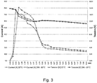
- Figure 3 shows a graph of power of the capacitor module and rotations per min of the motor over time of an exemplary device according to the invention. Measurements were performed at 20°C and at -30°C, wherein for the latter the device was kept at - 30°C for 24 hrs prior to the measurement. The measurements were performed using a device according to the invention comprising a capacitor module with six capacitors (MaxWell 16V 58F ultra capacitor module) and a motor (Dr Mad Thrust 3000kv 70 mm EDF Runner Motor 4s version (29mm)).
- the power was measured at 20 °C and at -30°C for approximately 8 sec.
- the graph indicates that the power is above 700 W within the first 1.3 sec, and then decreases to 300 W at 3.5 sec and stays at a plateau of about 200 W until the end of the measurement.
- the rpm per min of the motor were also measured at 20°C and - 30°C for approximately 8 sec.
- the graph indicates that the rotation of the motor is above 45'000 rpm/min within the first 0.5 sec, decreases to 35'000 rpm/min after 3.5 sec and stays constant until the end of the measurement.
- the measurements show that there is no significant difference in performance (power and rotation per min) between a device according to the invention operated at 20°C and a device according to the invention operated at -30°C, which was at -30°C for 24 hrs prior to the measurement.
- Figure 4 shows a graph relating to current and tension over time of an exemplary device according to the invention.
- the measurements correspond to the performed measurements shown in the graph of figure 3 .
- Current and tension are plotted over time.
- the current of the system reaches a maximum of about 80 Ampere for both measurements (20°C and -30°C) within the first second upon activation, decreases to 20 Ampere within 4 sec and plateaus at about 15 Ampere till the end of the measurement at 8.3 sec.
- the tension of the system starts at about 16 Volt, decreases to 12 Volt after 2.5 sec and stays constant till the end of the measurement.
- the measurements show that there is also no significant difference in the electrical properties (current and tension) between a device according to the invention operated at 20°C and a device according to the invention operated at -30°C, which was at -30°C for 24 hrs prior to the measurement.
Landscapes
- Health & Medical Sciences (AREA)
- Business, Economics & Management (AREA)
- Pulmonology (AREA)
- General Health & Medical Sciences (AREA)
- Emergency Management (AREA)
- Engineering & Computer Science (AREA)
- General Engineering & Computer Science (AREA)
- Mechanical Engineering (AREA)
- Structures Of Non-Positive Displacement Pumps (AREA)
- Air Bags (AREA)
- Toys (AREA)
- Professional, Industrial, Or Sporting Protective Garments (AREA)
- Respiratory Apparatuses And Protective Means (AREA)
Claims (17)
- Dispositif (1) de gonflage d'un sac gonflable, comprenant- une première ouverture (11) permettant une entrée d'air atmosphérique,- une seconde ouverture (12) raccordée ou pouvant être raccordée au sac gonflable,- au moins un premier organe de gonflage mobile (13), de préférence une roue à aubes, qui est agencé entre ladite première ouverture (11) et ladite seconde ouverture (12),- un moteur (31), pour entraîner l'organe de gonflage mobile (13) et une source d'énergie pour alimenter le moteur (31) en énergie, caractérisé en ce que la source d'énergie comprend au moins un condensateur (21) en tant qu'alimentation d'énergie dudit moteur (31).
- Dispositif (1) selon la revendication 1, dans lequel l'au moins un condensateur (22) a une capacitance totale dans la plage de 20 à 90 F, de préférence de 50 F à 70 F, de manière davantage préférée de 58 F.
- Dispositif (1) selon la revendication 1 ou 2, dans lequel la source d'énergie est un module de condensateurs (21), dans lequel deux ou plus, de préférence six, condensateurs (22) sont connectés sur une platine principale (23).
- Dispositif (1) selon la revendication 3, dans lequel des condensateurs (22) du module de condensateurs (21) sont connectés en série.
- Dispositif (1) selon les revendications 3 et 4, dans lequel les condensateurs (22) sont choisis pour que le moteur (31) ait une puissance de plus de 700 W, de préférence de 700 à 1 200 W, pendant environ 2 s, lors d'un fonctionnement avec les condensateurs en pleine charge.
- Dispositif (1) selon les revendications 3 et 4, dans lequel les condensateurs (22) sont choisis pour que le courant soit au-delà de 50 A, de préférence de 50 à 80 A, pendant environ 2,5 s, lors d'un fonctionnement avec les condensateurs en pleine charge.
- Dispositif (1) selon l'une quelconque des revendications 1 à 6, comprenant une unité de commande (32) pour commander ledit moteur.
- Dispositif (1) selon la revendication 7, dans lequel ladite unité de commande (32) est associée à un mécanisme déclencheur, de préférence mécanique, qui déclenche le moteur (31) afin d'entraîner l'organe de gonflage mobile (13) lors d'une activation.
- Dispositif (1) selon l'une quelconque des revendications 1 à 8, dans lequel le dispositif comprend une soupape de retenue (15) entre la première ouverture (11) et la seconde ouverture (12) pour empêcher une perte de l'air entré après gonflage du sac gonflable, ladite soupape de retenue (15) étant de préférence agencée entre l'organe de gonflage mobile (13) et la première ouverture (11).
- Dispositif (1) selon l'une quelconque des revendications 1 à 8, dans lequel la première ouverture (11), la seconde ouverture (12) et l'organe de gonflage mobile, de préférence la roue à aubes, sont agencés de manière à former un ventilateur radial.
- Dispositif (1) selon l'une quelconque des revendications 1 à 10, dans lequel le dispositif comprend une interface pour une batterie qui est connectée ou peut être connectée au condensateur (22) afin de recharger le condensateur.
- Dispositif selon l'une quelconque des revendications 1 à 11, dans lequel le dispositif a une masse maximale dans la plage de 600 à 1 400 g, de préférence de 1 000 g.
- Dispositif selon l'une quelconque des revendications 1 ou 12, dans lequel le dispositif a une taille dans la plage de 150 à 250 mm x 100 à 200 m x 80 à 180 mm, de préférence de 190 mm x 140 mm x 130 mm.
- Dispositif selon l'une quelconque des revendications 1 à 13, comprenant un interrupteur principal.
- Système de sécurité vis-à-vis des avalanches comprenant un dispositif (1) selon l'une quelconque des revendications 1 à 14 et un sac gonflable attaché au dispositif.
- Sac à dos comprenant un dispositif (1) selon l'une quelconque des revendications 1 à 14 et un sac gonflable attaché au dispositif.
- Utilisation d'un condensateur (22), de préférence un module de condensateurs (21), en tant qu'alimentation de puissance d'un moteur (31) pour entraîner un organe de gonflage mobile (13) dans un dispositif (1) selon l'une quelconque des revendications 1 à 14 pour un système de sécurité vis-à-vis des avalanches comprenant un sac gonflable.
Priority Applications (5)
| Application Number | Priority Date | Filing Date | Title |
|---|---|---|---|
| ES16154686.6T ES2678405T3 (es) | 2016-02-08 | 2016-02-08 | Dispositivo para inflar una bolsa inflable, sistema de seguridad en avalanchas y mochila con dicho dispositivo y su uso |
| EP16154686.6A EP3202462B1 (fr) | 2016-02-08 | 2016-02-08 | Dispositif pour gonfler un sac gonflable, système de sécurité à avalanche et sac à dos avec un tel dispositif et utilisation |
| US16/072,966 US20190030379A1 (en) | 2016-02-08 | 2017-01-24 | Device for inflating an inflatable bag, avalanche safety system and a backpack with such a device and use |
| CA3011202A CA3011202C (fr) | 2016-02-08 | 2017-01-24 | Dispositif permettant de gonfler un sac gonflable, systeme de securite d'avalanche et sac a dos comportant ledit dispositif et utilisation |
| PCT/EP2017/051353 WO2017137244A1 (fr) | 2016-02-08 | 2017-01-24 | Dispositif permettant de gonfler un sac gonflable, système de sécurité d'avalanche et sac à dos comportant ledit dispositif et utilisation |
Applications Claiming Priority (1)
| Application Number | Priority Date | Filing Date | Title |
|---|---|---|---|
| EP16154686.6A EP3202462B1 (fr) | 2016-02-08 | 2016-02-08 | Dispositif pour gonfler un sac gonflable, système de sécurité à avalanche et sac à dos avec un tel dispositif et utilisation |
Publications (2)
| Publication Number | Publication Date |
|---|---|
| EP3202462A1 EP3202462A1 (fr) | 2017-08-09 |
| EP3202462B1 true EP3202462B1 (fr) | 2018-04-18 |
Family
ID=55361346
Family Applications (1)
| Application Number | Title | Priority Date | Filing Date |
|---|---|---|---|
| EP16154686.6A Active EP3202462B1 (fr) | 2016-02-08 | 2016-02-08 | Dispositif pour gonfler un sac gonflable, système de sécurité à avalanche et sac à dos avec un tel dispositif et utilisation |
Country Status (5)
| Country | Link |
|---|---|
| US (1) | US20190030379A1 (fr) |
| EP (1) | EP3202462B1 (fr) |
| CA (1) | CA3011202C (fr) |
| ES (1) | ES2678405T3 (fr) |
| WO (1) | WO2017137244A1 (fr) |
Families Citing this family (5)
| Publication number | Priority date | Publication date | Assignee | Title |
|---|---|---|---|---|
| FR3036624B1 (fr) * | 2015-05-27 | 2018-03-23 | Nic Impex | Dispositif de gonflage de multiples enveloppes |
| DE102018101833B4 (de) | 2018-01-26 | 2022-05-19 | Ortovox Sportartikel Gmbh | Lawinenairbagsystem, Trageinrichtung und Verfahren zum Betreiben eines Lawinenairbagsystems |
| EP3517179B1 (fr) | 2018-01-26 | 2020-09-09 | Ortovox Sportartikel GmbH | Système de coussin gonflable d'avalanche, dispositif porteur doté d'un système de coussin gonflable d'avalanche et procédé de fonctionnement d'un système de coussin gonflable d'avalanche |
| EP3517181B1 (fr) | 2018-01-26 | 2020-09-30 | Ortovox Sportartikel GmbH | Système de coussin gonflables d'avalanche, dispositif d'usure et procédé de fonctionnement d'un système de coussin gonflables d'avalanche |
| EP3812011A1 (fr) | 2019-10-25 | 2021-04-28 | RAS Technology S.à.r.l. | Sac gonflable, sac à dos anti-avalanche et procédé de dégonflage d'un sac gonflable |
Family Cites Families (12)
| Publication number | Priority date | Publication date | Assignee | Title |
|---|---|---|---|---|
| US7408453B2 (en) * | 2001-02-16 | 2008-08-05 | Automotive Technologies International, Inc. | Wheel-mounted tire pumping and energy generating system and method |
| GB0109743D0 (en) * | 2001-04-19 | 2001-06-13 | Atkin Design And Dev Ltd | Electrical power supply |
| US20070053140A1 (en) * | 2005-09-02 | 2007-03-08 | Maxwell Technologies, Inc. | Flexible enclosure for energy storage devices |
| JP2008299300A (ja) * | 2007-05-31 | 2008-12-11 | Kazuko Takawashi | 事故防止用視認装置 |
| US8876568B2 (en) | 2010-09-14 | 2014-11-04 | Arc'teryx Equipment Inc. | Airbag rescue system |
| EP2700433B1 (fr) | 2012-08-24 | 2020-03-11 | Black Diamond Equipment Europe GmbH | Systèmes et procédés de protection d'avalanche gonflable avec regonflage |
| US9500117B2 (en) * | 2013-03-12 | 2016-11-22 | Briggs & Stratton Corporation | Cooling system for air-cooled engine |
| CN103291632A (zh) * | 2013-06-14 | 2013-09-11 | 天津翔驰电子有限公司 | 一种利用超级电容储电的太阳能风扇 |
| US9859719B2 (en) * | 2013-06-17 | 2018-01-02 | Nokia Technologies Oy | Method and apparatus for wireless power transfer |
| US9613760B2 (en) * | 2014-06-12 | 2017-04-04 | Corning Incorporated | Energy storage device and methods for making and use |
| CN204444536U (zh) * | 2014-12-25 | 2015-07-08 | 张丽玉 | 一种太阳能自动充气伞 |
| CN205277872U (zh) * | 2015-12-08 | 2016-06-01 | 杭州嘉凯医疗器械科技有限公司 | 医疗用便携式充气泵 |
-
2016
- 2016-02-08 EP EP16154686.6A patent/EP3202462B1/fr active Active
- 2016-02-08 ES ES16154686.6T patent/ES2678405T3/es active Active
-
2017
- 2017-01-24 CA CA3011202A patent/CA3011202C/fr active Active
- 2017-01-24 WO PCT/EP2017/051353 patent/WO2017137244A1/fr active Application Filing
- 2017-01-24 US US16/072,966 patent/US20190030379A1/en active Pending
Non-Patent Citations (1)
| Title |
|---|
| None * |
Also Published As
| Publication number | Publication date |
|---|---|
| US20190030379A1 (en) | 2019-01-31 |
| WO2017137244A1 (fr) | 2017-08-17 |
| CA3011202C (fr) | 2021-06-08 |
| CA3011202A1 (fr) | 2017-08-17 |
| ES2678405T3 (es) | 2018-08-10 |
| EP3202462A1 (fr) | 2017-08-09 |
Similar Documents
| Publication | Publication Date | Title |
|---|---|---|
| EP3202462B1 (fr) | Dispositif pour gonfler un sac gonflable, système de sécurité à avalanche et sac à dos avec un tel dispositif et utilisation | |
| RU2587789C2 (ru) | Система защиты с воздушной подушкой безопасности | |
| US9637210B2 (en) | Electric powered inflation system | |
| US20110158834A1 (en) | Built-in electric air pump for use in inflatable products | |
| US11370189B2 (en) | Motor vehicle comprising a compressor assembly | |
| CN106996464B (zh) | 用于气力输送系统中的圆顶阀及圆顶阀自动控制系统 | |
| US6525507B2 (en) | Solar system for a motor vehicle | |
| WO2006053318A3 (fr) | Dispositif de maintien de la pression de gonflage des pneumatiques | |
| KR101682399B1 (ko) | 무선 핸드 안마기 | |
| US20230131907A1 (en) | Inflatable bag, avalanche backpack and method of deflating an inflatable bag | |
| CN207330029U (zh) | 一种电梯载荷测试装置 | |
| KR20090098878A (ko) | 이젝터 장치 | |
| EP3760866A1 (fr) | Pompe à air intégrée multi-pression | |
| CN104234938B (zh) | 双套杆可升降式垂直风力发电机 | |
| US10358039B1 (en) | Vehicle turbine system | |
| CN103775362B (zh) | 外置式自动控制智能气泵 | |
| CN218760515U (zh) | 一种气囊充放气机构 | |
| CN115836165A (zh) | 挥发性材料输送装置 | |
| US11311754B2 (en) | Avalanche airbag system, carrying device, and method for operating an avalanche airbag system | |
| CN214092371U (zh) | 一种电动充气泵 | |
| CN218151526U (zh) | 一种手持式充抽一体气泵 | |
| JP6572642B2 (ja) | Iabp駆動装置及びiabp駆動装置における送風機の動作制御方法 | |
| CN212305239U (zh) | 一种具有充气功能的储能装置及储能系统 | |
| CN216477938U (zh) | 一种便携式多用途外置充气泵 | |
| CN219529386U (zh) | 一种适用充气产品的内置充气装置及充气产品 |
Legal Events
| Date | Code | Title | Description |
|---|---|---|---|
| PUAI | Public reference made under article 153(3) epc to a published international application that has entered the european phase |
Free format text: ORIGINAL CODE: 0009012 |
|
| STAA | Information on the status of an ep patent application or granted ep patent |
Free format text: STATUS: THE APPLICATION HAS BEEN PUBLISHED |
|
| AK | Designated contracting states |
Kind code of ref document: A1 Designated state(s): AL AT BE BG CH CY CZ DE DK EE ES FI FR GB GR HR HU IE IS IT LI LT LU LV MC MK MT NL NO PL PT RO RS SE SI SK SM TR |
|
| AX | Request for extension of the european patent |
Extension state: BA ME |
|
| STAA | Information on the status of an ep patent application or granted ep patent |
Free format text: STATUS: REQUEST FOR EXAMINATION WAS MADE |
|
| 17P | Request for examination filed |
Effective date: 20170828 |
|
| RBV | Designated contracting states (corrected) |
Designated state(s): AL AT BE BG CH CY CZ DE DK EE ES FI FR GB GR HR HU IE IS IT LI LT LU LV MC MK MT NL NO PL PT RO RS SE SI SK SM TR |
|
| GRAP | Despatch of communication of intention to grant a patent |
Free format text: ORIGINAL CODE: EPIDOSNIGR1 |
|
| STAA | Information on the status of an ep patent application or granted ep patent |
Free format text: STATUS: GRANT OF PATENT IS INTENDED |
|
| INTG | Intention to grant announced |
Effective date: 20171205 |
|
| GRAS | Grant fee paid |
Free format text: ORIGINAL CODE: EPIDOSNIGR3 |
|
| GRAA | (expected) grant |
Free format text: ORIGINAL CODE: 0009210 |
|
| STAA | Information on the status of an ep patent application or granted ep patent |
Free format text: STATUS: THE PATENT HAS BEEN GRANTED |
|
| AK | Designated contracting states |
Kind code of ref document: B1 Designated state(s): AL AT BE BG CH CY CZ DE DK EE ES FI FR GB GR HR HU IE IS IT LI LT LU LV MC MK MT NL NO PL PT RO RS SE SI SK SM TR |
|
| REG | Reference to a national code |
Ref country code: GB Ref legal event code: FG4D |
|
| REG | Reference to a national code |
Ref country code: CH Ref legal event code: EP |
|
| REG | Reference to a national code |
Ref country code: AT Ref legal event code: REF Ref document number: 989815 Country of ref document: AT Kind code of ref document: T Effective date: 20180515 |
|
| REG | Reference to a national code |
Ref country code: IE Ref legal event code: FG4D |
|
| REG | Reference to a national code |
Ref country code: DE Ref legal event code: R096 Ref document number: 602016002427 Country of ref document: DE |
|
| REG | Reference to a national code |
Ref country code: CH Ref legal event code: NV Representative=s name: HEPP WENGER RYFFEL AG, CH |
|
| REG | Reference to a national code |
Ref country code: ES Ref legal event code: FG2A Ref document number: 2678405 Country of ref document: ES Kind code of ref document: T3 Effective date: 20180810 |
|
| REG | Reference to a national code |
Ref country code: NL Ref legal event code: MP Effective date: 20180418 |
|
| REG | Reference to a national code |
Ref country code: LT Ref legal event code: MG4D |
|
| PG25 | Lapsed in a contracting state [announced via postgrant information from national office to epo] |
Ref country code: NL Free format text: LAPSE BECAUSE OF FAILURE TO SUBMIT A TRANSLATION OF THE DESCRIPTION OR TO PAY THE FEE WITHIN THE PRESCRIBED TIME-LIMIT Effective date: 20180418 |
|
| PG25 | Lapsed in a contracting state [announced via postgrant information from national office to epo] |
Ref country code: SE Free format text: LAPSE BECAUSE OF FAILURE TO SUBMIT A TRANSLATION OF THE DESCRIPTION OR TO PAY THE FEE WITHIN THE PRESCRIBED TIME-LIMIT Effective date: 20180418 Ref country code: PL Free format text: LAPSE BECAUSE OF FAILURE TO SUBMIT A TRANSLATION OF THE DESCRIPTION OR TO PAY THE FEE WITHIN THE PRESCRIBED TIME-LIMIT Effective date: 20180418 Ref country code: AL Free format text: LAPSE BECAUSE OF FAILURE TO SUBMIT A TRANSLATION OF THE DESCRIPTION OR TO PAY THE FEE WITHIN THE PRESCRIBED TIME-LIMIT Effective date: 20180418 Ref country code: NO Free format text: LAPSE BECAUSE OF FAILURE TO SUBMIT A TRANSLATION OF THE DESCRIPTION OR TO PAY THE FEE WITHIN THE PRESCRIBED TIME-LIMIT Effective date: 20180718 Ref country code: BG Free format text: LAPSE BECAUSE OF FAILURE TO SUBMIT A TRANSLATION OF THE DESCRIPTION OR TO PAY THE FEE WITHIN THE PRESCRIBED TIME-LIMIT Effective date: 20180718 Ref country code: FI Free format text: LAPSE BECAUSE OF FAILURE TO SUBMIT A TRANSLATION OF THE DESCRIPTION OR TO PAY THE FEE WITHIN THE PRESCRIBED TIME-LIMIT Effective date: 20180418 Ref country code: LT Free format text: LAPSE BECAUSE OF FAILURE TO SUBMIT A TRANSLATION OF THE DESCRIPTION OR TO PAY THE FEE WITHIN THE PRESCRIBED TIME-LIMIT Effective date: 20180418 |
|
| PG25 | Lapsed in a contracting state [announced via postgrant information from national office to epo] |
Ref country code: GR Free format text: LAPSE BECAUSE OF FAILURE TO SUBMIT A TRANSLATION OF THE DESCRIPTION OR TO PAY THE FEE WITHIN THE PRESCRIBED TIME-LIMIT Effective date: 20180719 Ref country code: RS Free format text: LAPSE BECAUSE OF FAILURE TO SUBMIT A TRANSLATION OF THE DESCRIPTION OR TO PAY THE FEE WITHIN THE PRESCRIBED TIME-LIMIT Effective date: 20180418 Ref country code: HR Free format text: LAPSE BECAUSE OF FAILURE TO SUBMIT A TRANSLATION OF THE DESCRIPTION OR TO PAY THE FEE WITHIN THE PRESCRIBED TIME-LIMIT Effective date: 20180418 Ref country code: LV Free format text: LAPSE BECAUSE OF FAILURE TO SUBMIT A TRANSLATION OF THE DESCRIPTION OR TO PAY THE FEE WITHIN THE PRESCRIBED TIME-LIMIT Effective date: 20180418 |
|
| PG25 | Lapsed in a contracting state [announced via postgrant information from national office to epo] |
Ref country code: PT Free format text: LAPSE BECAUSE OF FAILURE TO SUBMIT A TRANSLATION OF THE DESCRIPTION OR TO PAY THE FEE WITHIN THE PRESCRIBED TIME-LIMIT Effective date: 20180820 |
|
| REG | Reference to a national code |
Ref country code: DE Ref legal event code: R097 Ref document number: 602016002427 Country of ref document: DE |
|
| PG25 | Lapsed in a contracting state [announced via postgrant information from national office to epo] |
Ref country code: DK Free format text: LAPSE BECAUSE OF FAILURE TO SUBMIT A TRANSLATION OF THE DESCRIPTION OR TO PAY THE FEE WITHIN THE PRESCRIBED TIME-LIMIT Effective date: 20180418 Ref country code: CZ Free format text: LAPSE BECAUSE OF FAILURE TO SUBMIT A TRANSLATION OF THE DESCRIPTION OR TO PAY THE FEE WITHIN THE PRESCRIBED TIME-LIMIT Effective date: 20180418 Ref country code: EE Free format text: LAPSE BECAUSE OF FAILURE TO SUBMIT A TRANSLATION OF THE DESCRIPTION OR TO PAY THE FEE WITHIN THE PRESCRIBED TIME-LIMIT Effective date: 20180418 Ref country code: RO Free format text: LAPSE BECAUSE OF FAILURE TO SUBMIT A TRANSLATION OF THE DESCRIPTION OR TO PAY THE FEE WITHIN THE PRESCRIBED TIME-LIMIT Effective date: 20180418 Ref country code: SK Free format text: LAPSE BECAUSE OF FAILURE TO SUBMIT A TRANSLATION OF THE DESCRIPTION OR TO PAY THE FEE WITHIN THE PRESCRIBED TIME-LIMIT Effective date: 20180418 |
|
| PLBE | No opposition filed within time limit |
Free format text: ORIGINAL CODE: 0009261 |
|
| STAA | Information on the status of an ep patent application or granted ep patent |
Free format text: STATUS: NO OPPOSITION FILED WITHIN TIME LIMIT |
|
| PG25 | Lapsed in a contracting state [announced via postgrant information from national office to epo] |
Ref country code: SM Free format text: LAPSE BECAUSE OF FAILURE TO SUBMIT A TRANSLATION OF THE DESCRIPTION OR TO PAY THE FEE WITHIN THE PRESCRIBED TIME-LIMIT Effective date: 20180418 |
|
| 26N | No opposition filed |
Effective date: 20190121 |
|
| PG25 | Lapsed in a contracting state [announced via postgrant information from national office to epo] |
Ref country code: MC Free format text: LAPSE BECAUSE OF FAILURE TO SUBMIT A TRANSLATION OF THE DESCRIPTION OR TO PAY THE FEE WITHIN THE PRESCRIBED TIME-LIMIT Effective date: 20180418 Ref country code: LU Free format text: LAPSE BECAUSE OF NON-PAYMENT OF DUE FEES Effective date: 20190208 |
|
| REG | Reference to a national code |
Ref country code: BE Ref legal event code: MM Effective date: 20190228 |
|
| REG | Reference to a national code |
Ref country code: IE Ref legal event code: MM4A |
|
| PG25 | Lapsed in a contracting state [announced via postgrant information from national office to epo] |
Ref country code: IE Free format text: LAPSE BECAUSE OF NON-PAYMENT OF DUE FEES Effective date: 20190208 |
|
| PG25 | Lapsed in a contracting state [announced via postgrant information from national office to epo] |
Ref country code: BE Free format text: LAPSE BECAUSE OF NON-PAYMENT OF DUE FEES Effective date: 20190228 |
|
| PG25 | Lapsed in a contracting state [announced via postgrant information from national office to epo] |
Ref country code: TR Free format text: LAPSE BECAUSE OF FAILURE TO SUBMIT A TRANSLATION OF THE DESCRIPTION OR TO PAY THE FEE WITHIN THE PRESCRIBED TIME-LIMIT Effective date: 20180418 |
|
| PG25 | Lapsed in a contracting state [announced via postgrant information from national office to epo] |
Ref country code: MT Free format text: LAPSE BECAUSE OF NON-PAYMENT OF DUE FEES Effective date: 20190208 |
|
| REG | Reference to a national code |
Ref country code: AT Ref legal event code: UEP Ref document number: 989815 Country of ref document: AT Kind code of ref document: T Effective date: 20180418 |
|
| PG25 | Lapsed in a contracting state [announced via postgrant information from national office to epo] |
Ref country code: CY Free format text: LAPSE BECAUSE OF FAILURE TO SUBMIT A TRANSLATION OF THE DESCRIPTION OR TO PAY THE FEE WITHIN THE PRESCRIBED TIME-LIMIT Effective date: 20180418 |
|
| PG25 | Lapsed in a contracting state [announced via postgrant information from national office to epo] |
Ref country code: IS Free format text: LAPSE BECAUSE OF FAILURE TO SUBMIT A TRANSLATION OF THE DESCRIPTION OR TO PAY THE FEE WITHIN THE PRESCRIBED TIME-LIMIT Effective date: 20180818 |
|
| PG25 | Lapsed in a contracting state [announced via postgrant information from national office to epo] |
Ref country code: HU Free format text: LAPSE BECAUSE OF FAILURE TO SUBMIT A TRANSLATION OF THE DESCRIPTION OR TO PAY THE FEE WITHIN THE PRESCRIBED TIME-LIMIT; INVALID AB INITIO Effective date: 20160208 |
|
| PG25 | Lapsed in a contracting state [announced via postgrant information from national office to epo] |
Ref country code: SI Free format text: LAPSE BECAUSE OF FAILURE TO SUBMIT A TRANSLATION OF THE DESCRIPTION OR TO PAY THE FEE WITHIN THE PRESCRIBED TIME-LIMIT Effective date: 20180418 |
|
| PG25 | Lapsed in a contracting state [announced via postgrant information from national office to epo] |
Ref country code: MK Free format text: LAPSE BECAUSE OF FAILURE TO SUBMIT A TRANSLATION OF THE DESCRIPTION OR TO PAY THE FEE WITHIN THE PRESCRIBED TIME-LIMIT Effective date: 20180418 |
|
| PGFP | Annual fee paid to national office [announced via postgrant information from national office to epo] |
Ref country code: FR Payment date: 20230110 Year of fee payment: 8 |
|
| PGFP | Annual fee paid to national office [announced via postgrant information from national office to epo] |
Ref country code: IT Payment date: 20230110 Year of fee payment: 8 |
|
| PGFP | Annual fee paid to national office [announced via postgrant information from national office to epo] |
Ref country code: CH Payment date: 20230426 Year of fee payment: 8 |
|
| PGFP | Annual fee paid to national office [announced via postgrant information from national office to epo] |
Ref country code: ES Payment date: 20240306 Year of fee payment: 9 |
|
| PGFP | Annual fee paid to national office [announced via postgrant information from national office to epo] |
Ref country code: AT Payment date: 20240125 Year of fee payment: 9 |
|
| PGFP | Annual fee paid to national office [announced via postgrant information from national office to epo] |
Ref country code: DE Payment date: 20240116 Year of fee payment: 9 Ref country code: GB Payment date: 20240118 Year of fee payment: 9 |