EP3201990B1 - Anschlussklemme - Google Patents
Anschlussklemme Download PDFInfo
- Publication number
- EP3201990B1 EP3201990B1 EP15797343.9A EP15797343A EP3201990B1 EP 3201990 B1 EP3201990 B1 EP 3201990B1 EP 15797343 A EP15797343 A EP 15797343A EP 3201990 B1 EP3201990 B1 EP 3201990B1
- Authority
- EP
- European Patent Office
- Prior art keywords
- conductor
- cutting
- insulation displacement
- contact element
- connection terminal
- Prior art date
- Legal status (The legal status is an assumption and is not a legal conclusion. Google has not performed a legal analysis and makes no representation as to the accuracy of the status listed.)
- Active
Links
Images




Classifications
-
- H—ELECTRICITY
- H01—ELECTRIC ELEMENTS
- H01R—ELECTRICALLY-CONDUCTIVE CONNECTIONS; STRUCTURAL ASSOCIATIONS OF A PLURALITY OF MUTUALLY-INSULATED ELECTRICAL CONNECTING ELEMENTS; COUPLING DEVICES; CURRENT COLLECTORS
- H01R4/00—Electrically-conductive connections between two or more conductive members in direct contact, i.e. touching one another; Means for effecting or maintaining such contact; Electrically-conductive connections having two or more spaced connecting locations for conductors and using contact members penetrating insulation
- H01R4/24—Connections using contact members penetrating or cutting insulation or cable strands
- H01R4/2416—Connections using contact members penetrating or cutting insulation or cable strands the contact members having insulation-cutting edges, e.g. of tuning fork type
Definitions
- the present invention relates to a connecting terminal for connecting one or more insulated conductors, comprising a housing with one or more conductor receptacles and a contact spring which contacts one or more cutting contact elements which are rotatably mounted on the housing about an axis A.
- an insulation displacement contact element penetrates at least one insulation of a conductor section introduced into a conductor receptacle and makes contact with the conductor in question.
- connection terminals are characterized in that the conductor does not have to be stripped beforehand in order to connect an insulated conductor. Rather, such connection terminals are designed to enable the insulation to be separated and the conductor to be contacted in one work step.
- Such "insulation displacement terminals" offer advantages over conventional connection terminals, since insulated conductors can be connected to such a connection terminal in a time-efficient and convenient manner.
- available insulation displacement terminals are only suitable to a limited extent for reliably contacting many different types of insulated conductors in the course of connection to the connecting terminal and at the same time ensuring easy operation by the installer.
- the invention is based on the object of specifying an improved connection terminal of the type mentioned at the beginning.
- this object is achieved by a connecting terminal with the features of claim 1, and in particular in that at least one cutting contact element is mounted such that it can be displaced in the axial direction and has at least two cutting blades which are integrally connected to one another and which, when rotated about axis A penetrate into a respective conductor receptacle in order to connect both conductors directly to one another in an electrically conductive manner only via the cutting contact element.
- connection terminal with the features of claim 2, and in particular in that at least two cutting contact elements are mounted displaceably in the axial direction and each have at least one cutting blade, both cutting blades when the cutting contact elements are rotated the axis A penetrate into one and the same conductor receptacle in order to contact the conductor from two opposite sides.
- At least two insulated conductors are electrically conductively connected to one another in that the at least one cutting contact element has two cutting blades connected in one piece, a single cutting blade penetrating the insulation of an associated conductor section and making contact with the conductor when the cutting contact element is connected to the cutting blades is rotated around axis A. Since the cutting blades are integrally connected to one another via the cutting contact element, a direct electrical connection is established without intermediate contacts between the conductors when one of the cutting blades contacts one conductor and the other cutting blade contacts the other conductor (or vice versa). The cutting blades are each inserted into an assigned conductor receptacle by the rotation of the insulation displacement contact element, in which an (insulated) conductor section is held.
- the conductor insulation in question is severed along a section by the inserted cutting knife and the cutting knife makes contact with the conductor in question with at least one cutting edge section in order to produce an almost resistance-free connection between the conductor and the cutting contact element.
- the cutting blades and the cutting contact element are formed from an electrically conductive material, preferably a metal.
- the one-piece connection of the two cutting blades has the advantage that the electrical connection between the two conductors is established directly, i.e. without additional contact points. In principle, these would be useful to cut the cutting knives e.g. to be used by punctual or flat contact with each other via connecting elements.
- the corresponding contact points can, however, be caused by dirt or other deposits, e.g. Oxidation deposits, be disturbed with regard to an electrical connection.
- a contact point can act as an undesirable electrical resistance. In the worst case, a contact point can even be completely disturbed, so that no electrical connection at all is established between the parts to be contacted (corresponding to a very high or infinitely high resistance). Such a malfunction is avoided from the outset by the cutting blades that are connected to one another in one piece, as a result of which the reliability of the connection terminal is improved, in particular with regard to longevity.
- the contact spring of the connection terminal mentioned at the beginning makes contact with the insulation displacement contact element and serves as an electrical connection element of the connection terminal.
- the contact spring can be provided to the conductor connected to the insulation displacement contact element with electrical contact elements, eg a socket or a distributor to connect electrically.
- the contact spring preferably has at least one nose which engages the cutting contact element in order to ensure particularly secure contact. Additionally or alternatively, the contact spring can rest flat against the cutting contact element, at least in sections.
- connection terminal can be used to connect at least one insulated conductor, the insulated conductor with a conductor section first being inserted into a conductor receptacle of the connection terminal.
- the connection terminal comprises at least two cutting contact elements, which are preferably arranged on two opposite sides of the conductor receptacle and are rotatably mounted about the axis A.
- Each of the two cutting contact elements has at least one cutting knife. With a simultaneous rotation of the cutting contact elements around the axis A, the respective cutting blades penetrate the conductor receptacle while rotating, severing the insulation of the conductor section inserted into the conductor receptacle and contacting the conductor from two opposite sides with at least one cutting edge section each.
- connection terminal permits particularly reliable contacting of the insulated conductor, since it is sufficient for contacting the conductor that one of the cutting contact elements makes contact with the conductor via a cutting blade, ie one of the cutting contact elements serves as a "reserve". It must be taken into account that both insulation displacement contact elements make contact with the contact spring, which can serve as the electrical connection element of the connection terminal, and an electrical connection to the conductor is established even if only one insulation displacement contact element makes contact with the conductor.
- the cutting blades can support one another via the conductor section, in particular while they are cutting through the conductor insulation.
- the conductor section is clamped between the cutting blades.
- the cutting blades form a frictional connection with the conductor section, i. a force which is transmitted from one cutting knife to the conductor is at least partially transmitted to the other cutting knife via the conductor. Should the ladder section e.g.
- the conductor section is at least partially pushed in the direction of the second cutting knife.
- a cutting knife which has become too blunt as a result of use to cut through conductor insulation can nevertheless contribute to the fact that the opposite cutting knife cuts through the insulation and makes contact with the conductor.
- the force required to make contact with the conductor can be reduced by the mutual force transmission between the insulation displacement contact elements and the conductor section, as a result of which an installer has to use less force to connect the conductor to the connecting terminal.
- the connected conductor is particularly securely fixed in the conductor holder by the opposing arrangement of the cutting contact elements or cutting blades.
- the cutting blades preferably cut into the conductor insulation along a section defined essentially perpendicular to the axial extension of the conductor section, so that in particular a displacement of the conductor section in the direction of the axial extension of the conductor section is blocked by the cutting blades engaging the insulation.
- the connected conductor is thereby particularly well secured against inadvertent detachment of the conductor from the connection terminal, for example by pulling the conductor.
- each cutting contact element is mounted displaceably in the axial direction.
- This feature enables insulated conductors of different thicknesses to be connected to the connection terminal, since each insulation displacement contact element can be offset depending on the insulation and conductor thickness in such a way that a cutting knife of the insulation displacement contact element cuts through the insulation and contacts the conductor without damaging the conductor itself or cut through.
- insulation thickness refers to the diameter of the insulated conductor in the radial direction.
- the conductor thickness corresponds to the diameter of the conductor.
- the thickness of the insulation can often vary greatly for conductor types with the same conductor thickness, whereby the insulation thickness can be significantly greater than the conductor thickness.
- each insulation displacement contact element is preferably mounted so that it can slide in the axial direction.
- the connection terminal can therefore be used universally for many conductor types with different insulation and conductor thicknesses.
- the contact spring biases at least one cutting contact element in the axial direction in the direction of at least one conductor receptacle.
- the contact spring preloads the relevant insulation displacement contact element in the axial direction in the direction of the conductor receptacles in question.
- the cutting contact element is supported in particular between the contact spring and the conductor receptacle, the pre-tensioning of the insulation displacement contact element preferably ensuring that the insulation displacement contact element penetrates the insulation of the conductor section inserted into the conductor receptacle during the rotation about the axis A without the insulation displacement contact element being displaced axially by the conductor section counter to the biasing direction.
- the pretensioning force of the contact spring is preferably selected to be at least so great that the cutting contact element with the relevant cutting blades can safely penetrate or cut through the insulation of all common conductor types without the relevant cutting contact element being offset by a conductor section.
- the pretensioning force of the contact spring is preferably so small that the cutting contact element is displaced by the conductor in the opposite direction to the biasing direction when a cutting knife engages the conductor, i.e. the conductor will not be damaged or cut by the cutting knife. In addition, damage to the cutting knife or other parts of the connection terminal is avoided in this way.
- the pretensioning force of the contact spring is preferably designed to ensure that an insulated conductor is connected with as little force and friction as possible, ensuring reliable penetration of the insulation and contacting the conductor on the one hand, and the retraction of the cutting contact element in question when it touches the conductor on the other hand.
- the contact spring biases the IDC contact elements in the axial direction in opposite directions in the direction of the conductor receptacle concerned.
- Each cutting contact element preferably comprises a contact disk, at least one cutting blade extending away from the contact disk in the axial direction extends and is electrically conductively connected to it.
- each cutting knife is aligned on a cutting contact element parallel to the axis A, as a result of which, when the cutting contact element rotates about the axis A, the conductor insulation can be penetrated through the relevant cutting knife with little force.
- Each cutting knife preferably has at least one cutting edge section which is oriented in the direction of an associated conductor receptacle.
- each cutting knife is preferably designed as a segment of a cylinder jacket surface.
- a cutting knife designed in this way is preferably arranged on a cutting contact element in such a way that the cylinder axis of the cylinder jacket surface runs coaxially to the axis A. In other words, the cutting knife is curved about the axis A. When the cutting contact element rotates about the axis A, the cutting blade can thus cut through a conductor insulation with particularly little force.
- two cutting blades provided on a cutting contact element are arranged diametrically opposite one another in the radial direction. This prevents the cutting contact element from tilting if the cutting contact element penetrates two conductor insulations with the cutting blades when it rotates about the axis A. Tilting is caused by tilting or twisting the cutting contact element from a reference plane which preferably extends perpendicular to the axis A. Otherwise, by tilting or rotating out of the reference plane, the cutting contact element could tilt, for example in the housing, as a result of which the rotation of the cutting contact element is hindered or blocked.
- the cutting knives preferably extend perpendicular to the reference plane and are arranged diametrically opposite one another about the axis A, that is to say axially symmetrical.
- a cutting knife has at least two straight cutting edge sections which enclose an obtuse angle to one another or are connected to one another by a curved cutting edge section. This feature ensures that when the cutting blade is rotated, the insulation of the relevant conductor section is severed tangentially.
- one of the two straight cutting edge sections engages tangentially on the conductor insulation and is guided along a circular path around the axis A through the insulation of the conductor, the cutting knife severing the insulation by pulling or pushing cuts.
- the tangential cutting edge has the advantage that the conductor insulation is evenly cut through with a largely constant effort. As a result, pleasant, uniform tactile feedback can be made available to the installer when the cutting contact element is rotated, i.e. an uneven and possibly irritating effort is avoided when rotating the cutting contact element.
- the cutting edge section acting tangentially also has the advantage that the cutting edge section, after penetrating the insulation, also tangentially acts on the conductor enclosed by the conductor insulation.
- the cutting knife in question can therefore be moved particularly well through the conductor and can slide along the conductor without damaging or severing it.
- the conductor section is preferably arranged in a stationary manner in the conductor receptacle, so that the cutting knife is offset axially against the pretensioning direction of the cutting contact element by a first straight cutting edge section sliding along the conductor until the cutting knife passes the conductor when it rotates and a second cutting edge section hits slides along the conductor and contacts it.
- two conductor receptacles extend through the housing in a plane perpendicular to the axis A.
- the conductor receptacles are arranged one above the other perpendicular to the axis A, which ensures a compact design of the connection terminal.
- the housing and / or a conductor receptacle have at least one lateral penetration section which delimits a range of rotation of a cutting contact element.
- two stops can be defined for the IDC contact element in order to facilitate the connection of an insulated conductor to the connection terminal.
- the range of rotation is preferably determined such that the cutting contact element can be rotated between a connection position and a release position.
- the connection position at least one cutting blade of a cutting contact element penetrates a conductor insulation of a conductor section introduced into the conductor receptacle and makes contact with the conductor.
- the conductor section is fixed in the conductor receptacle by the cutting blade of the cutting contact element.
- the release position the mechanical and electrical connection (contacting) between the cutting contact element and the conductor is released and a conductor section can be inserted into the conductor receptacle or removed from it.
- a cutting contact element has at least one incision, which enables an axial movement of the cutting knife or the cutting knives that is decoupled from one another.
- such an incision increases the axial movability of a cutting knife relative to the cutting contact element, whereby in particular the axial movability of two cutting knives formed on a cutting contact element is also increased.
- several incisions can also be provided on the cutting contact element.
- One advantage of this decoupling is that the axial position can be adjusted a cutting blade can take place as a function of the thickness of an inserted conductor section independently of an axial movement of the cutting contact element, whereby in particular undesired tilting or tilting of the cutting contact element can be prevented.
- a cutting knife is preferably flexibly connected to the contact disk of a cutting contact element.
- the relevant cutting knife can be moved in the axial direction and / or radial direction, essentially decoupled from the contact disk. In particular, this ensures reliable contacting of the conductor and counteracts tilting or tilting of the cutting contact element.
- an actuating element for rotating the cutting contact element or the cutting contact elements, the actuating element comprising one or more coupling disks and an actuating extension, and wherein the actuating element can be coupled positively and / or non-positively and / or non-rotatably to a cutting contact element via a coupling disk .
- an actuating element enables a user of the connecting terminal to rotate the one or more cutting contact elements about the axis A without using additional tools in order to connect one or more insulated conductors to the connecting terminal.
- the actuation extension extends, for example, in a tangential, radial or axial direction away from the one or more coupling disks.
- a single actuation extension preferably acts on the one or more coupling disks, it also being possible for several actuation extensions to be provided, for example one actuation extension per coupling disc.
- an actuating element is preferably provided for both cutting contact elements in order to be able to rotate the cutting contact elements simultaneously, ie synchronously.
- the Cutting contact elements can be aligned in the same way with respect to a rotation about the axis A, or an angular offset or rotational offset can be provided between the cutting contact elements.
- Each coupling disk preferably has a recess for coupling a cutting contact element, the recess forming a radial guide for one or more cutting blades of the cutting contact element received and / or an axial guide for the cutting contact element and / or limiting twisting of the cutting contact element when the cutting contact element is in the Recess is added.
- the recess serves to receive a cutting contact element, the recess guiding the cutting blades formed on the received cutting contact element in the radial direction. This ensures in particular that the cutting knife or knives are guided on a circular path when the cutting contact element rotates about the axis A without the cutting knives "bending away" in the radial direction.
- the recess limits undesirable twisting of a cutting contact element, which counteracts tilting or jamming of the cutting contact element or parts of the cutting contact element.
- the axial guidance of the cutting contact element through the recess also contributes to this. This improves the durability and reliable operation of the terminal.
- At least one tongue of the coupling disk preferably extends into the recess, the tongue having a shape corresponding to an incision in the cutting contact element.
- the tongue can preferably be curved around the axis A, so that an inner edge of the incision engages the relevant outer edge of the tongue essentially perpendicular to the radial direction. This ensures a particularly uniform and secure radial guidance of the cutting knife or knives.
- the tongue improves the axial guidance of the cutting contact element.
- the contact spring comprises at least two spring arms which act on spaced-apart sections on a cutting contact element and preload it in the axial direction. In this way, tilting and a resulting blockage of the cutting contact element can be avoided, because tilting movements of the cutting contact element from a plane perpendicular to axis A (reference plane) are directly compensated by the spring arms engaging spaced sections.
- the contact spring preferably comprises at least two spring arms which preload two cutting blades provided on a cutting contact element independently of one another in the axial direction.
- This feature has the advantage that two conductor sections, which are each received in an assigned conductor receptacle, can differ significantly in diameter without the insulation displacement contact element has to be tilted in the reference plane to connect the conductors to the connection terminal.
- the two spring arms preload the cutting blades in the axial direction, in particular as a function of the conductor and insulation properties, without influencing the other cutting blade in an undesirable manner.
- the contact spring comprises at least one spring arm which prestresses a cutting blade provided on a cutting contact element in the axial direction essentially independently of the contact disk.
- the contact spring preferably engages around the insulation displacement contact element or the insulation displacement contact elements, the contact spring in particular additionally engaging around the housing and / or the conductor receptacle / conductor receptacles.
- the contact spring can for example be designed as a U-shaped spring. In the case of a connection terminal with a single insulation displacement contact element, the contact spring engages around the insulation displacement contact element and the housing and preloads the insulation displacement contact element in the axial direction in the direction of the housing. In the event that two cutting contact elements are provided, the contact spring engages around the two cutting contact elements and pretensions them in the axial direction in opposite directions in the direction of the housing or the conductor receptacles.
- the conductor receptacles are preferably integral, i. integrally formed on the housing. If the conductor receptacles are formed separately from the housing and connected to the housing, the contact spring preloads the insulation displacement contact element or the insulation displacement contact elements by reaching around in the direction of the conductor recepta
- the contact spring preferably engages around the actuating element. This prevents the actuating element from moving away from the cutting contact elements coupled to the actuating element when it rotates about the axis A can solve in that, for example, the coupling disk slips out of the contact disk of the cutting contact element.
- the contact spring thus ensures a secure coupling between the actuating element and the cutting contact elements, which are coupled to the actuating element.
- the actuating element has two coupling disks which are spaced apart from one another and which form an intermediate space for the conductor receptacle / conductor receptacles.
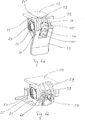
- connection terminal 11 The structure of a connection terminal 11 is initially based on Fig. 1a, 1b and 2nd explained.
- the connection terminal 11 comprises a housing 13 with integrally formed conductor receptacles 15 and 17, a contact spring 23, an actuating element 25 and cutting contact elements 19 and 21.
- the housing 13 and the actuating element 25 are made of plastic.
- the contact spring 23 and the cutting contact elements are made of metal and are electrically conductive.
- the actuation element 25 comprises an actuation extension 27 which extends from two coupling disks 29 and 31 in a tangential direction away from the coupling disks 29 and 31.
- the coupling disks 29 and 31 are arranged at a distance from one another and form an intermediate space 33.
- the cutting contact elements 19 and 21 are mirror-symmetrical in the embodiment shown, the cutting contact element 19 being described in detail below.
- the cutting contact element 19 has a contact disk 35 which is formed as a segment of a circular disk.
- Two cutting blades 37 and 39 extend diametrically opposite one another from an outer edge of the contact disk 35 perpendicular to the disk plane away from the contact disk 35.
- the cutting contact element 19 is in Figure 7a shown in an enlarged perspective view. Curved, tongue-shaped incisions 41 and 43 are formed in the contact disk 35, through which two disk arms 45 and 47 are formed on the contact disk 35.
- the cutting knife 37 is formed in one piece on the disk arm 45 and is connected to the contact disk 35 via a web 49.
- the cutting knife 39 is formed in one piece on the disk arm 47 and is connected to the contact disk 35 via a web 51.
- FIG. 7b the mirror-symmetrical cutting contact element 21 is shown, with cutting blades 53 and 55 extending from the inside of a contact disk 57 perpendicular to the disk plane away from the contact disk 37. Incisions 42 and 44 are formed in the insulation displacement contact element 21.
- the actuator 25 is in Fig. 3 shown in an enlarged perspective view.
- a recess 59 is formed for the form-fitting and rotationally fixed reception of the cutting contact element 19.
- Tongues 61 and 63 extend from the coupling disk 29 into the recess 59.
- the tongue 61 has a shape that is complementary to the incision 41 of the cutting contact element 19.
- the tongue 63 has a shape that is complementary to the incision 43 of the cutting contact element 19.
- the coupling disk 31 has a recess 65 for positively receiving the cutting contact element 21, with tongues (not shown) extending mirror-symmetrically to the coupling disk 29 into the recess 65, which correspond to the incisions 42 and 44 of the cutting contact element 21.
- connection terminal 11 is shown in an assembled and opened state.
- the actuating element 25 is rotatably mounted on the housing 13 about an axis A (cf. also Fig. 2 ).
- the conductor receptacles 15 and 17 formed integrally on the housing 13 are arranged in the intermediate space 33 of the actuating element 25.
- the cutting contact element 19 is received in the recess 59 of the coupling disk 29, the tongue 61 being inserted into the incision 41 and the tongue 63 being inserted into the incision 43.
- the cutting knife 37 is guided through a penetration section 67 formed on the housing 13 (cf. Fig. 2 ). In a corresponding manner, the cutting knife 39 is guided through a passage section 69.
- the cutting contact element 21 is received in the recess 65 of the coupling disk 31, the cutting blades 53 and 55 being connected to the through-engagement sections (not shown) Housing 13 are guided, which are formed mirror-symmetrically to the pass-through sections 67 and 69 on the opposite side of the housing 13 in the axial direction.
- the contact spring 23 comprises four spring arms 71, 73, 75 and 77, which in FIG Fig. 2 are shown.
- the contact spring 23 is formed in one piece, ie all spring arms 71, 73, 75 and 77 are formed integrally on the contact spring 23. Furthermore, the spring arms 71, 73, 75 and 77 have elastic properties.
- the connection terminal 11 is installed (cf. Fig. 1a ) the contact spring 23 engages around the coupling disks 29 and 31 as well as the cutting contact elements 19 and 21 received in the respective recesses 59 and 65.
- the contact spring 23 biases the cutting contact element 19 at spaced-apart sections of the contact disk 35 of the cutting contact element 19 in the axial direction in the direction of the conductor receptacles 15 and 17.
- the spring arm 71 of the contact spring 23 engages via a nose 79 ( Fig. 2 ) to the web 51 of the contact disk 35 (see. Also Figure 7a ).
- the spring arm 73 engages the contact disk 57 of the cutting contact element 21 via a nose 81 and preloads the cutting contact element 21 in the axial direction.
- the spring arms 71 and 73 thus tension the cutting contact elements 19 and 21 in the axial direction in opposite directions.
- the spring arm 75 of the contact spring 23 pretensions the cutting contact element 19 in the axial direction, the spring arm 75 engaging the web 49 of the contact disk 35 of the cutting contact element 19 via a nose 83.
- the spring arm 77 of the contact spring 23 biases the cutting contact element 21 via a nose 85 in an axially opposite direction.
- the contact spring 23 is electrically connected to the cutting contact elements 19 and 21 via the spring arms 71, 73, 75, 77, with the electrical contacting is established via the relevant lugs 79, 81, 83 and 85 independently of the rotational position of the cutting contact elements 19 and 21. Since the contact disk 35, the webs 49, 51, the disk arms 45, 47 and the cutting blades 37, 39 are integrally formed on the cutting contact element 19, all parts of the cutting contact element 19 are always at the same electrical potential. Via the noses 79, 83 of the spring arms 71, 75, the cutting contact element 19 is thus contacted twice and electrically particularly reliably with respect to all parts of the cutting contact element 19. Correspondingly, the cutting contact element 21 is contacted twice and completely via the noses 81, 85 of the spring arms 73, 77. Since the contact spring 23 is integrally formed, the cutting contact elements 19 and 21 are always electrically connected to one another.
- the actuating element 25 is moved around the axis A by manually actuating the actuating extension 27, starting from the position shown in FIG Fig. 1a Rotated position shown in mathematically positive direction until the actuating element 25 the in Figure 1b Has shown rotational position.
- the spring arm 71 of the contact spring 23 engages the disk arm 47 of the cutting contact element 19 via the nose 79 and thereby pretensions the cutting knife 39 in the axial direction in the direction of the conductor receptacle 17.
- connection terminal 11 Show this Fig. 4 , 5a and 5b sectional views of the connection terminal 11, which is used to describe how to connect insulated conductors.
- FIG. 4 the connection terminal 11 is shown in the closed state, the sectional plane running perpendicular to the axis A through the conductor receptacles 15 and 17.
- the cutting blade 53 of the cutting contact element 21 engages the conductor receptacle 15 on the rear and the cutting blade 55 of the cutting contact element 21 engages the conductor receptacle 17 on the rear.
- terminal 11 is closed accordingly Fig. 1a shown in the open state, the plane of section through the connecting terminal 11 in comparison to FIG Fig. 4 is set back slightly in the axial direction, so that the cutting blades 37 and 39 of the cutting contact element 19 are also shown.
- An insulated conductor 87 which in Figure 5a is only partially shown, is inserted into the conductor receptacle 15 with a conductor section 91.
- Another insulated conductor 89 is inserted into the conductor receptacle 17 with a conductor section 93.
- the conductor section 91 can be inserted into the conductor receptacle 15 from a front side of the connection terminal 11 or from a rear side of the connection terminal 11 through an opening 95 formed in the contact spring 23 ( Fig.
- the actuating element 25 is located in Figure 5a in a release position in which none of the cutting blades 37, 39, 53 and 55 engages in one of the conductor receptacles 15 and 17.
- the conductor sections 91 and 93 can thus optionally be introduced into the conductor receptacles 15 and 17 and led out.
- the cutting knife 55 contacts the conductor 99 and the cutting knife 53 contacts the conductor 97.
- the cutting knives 55 and 53 are correspondingly connected in one piece to one another via the contact disk 57 of the cutting contact element 21, whereby the conductors 97 and 99 are electrically connected directly to one another.
- the conductor 99 is clamped between the cutting blades 39 and 55 by the previously explained pretensioning of the spring arms 71 and 73, so that the conductor 99 is contacted in a particularly reliable manner and is fixed in the conductor receptacle 17.
- the conductor 97 is clamped between the cutting blades 37 and 53 due to the pretensioning explained by the spring arms 75 and 77, so that the conductor 97 is contacted in a particularly secure manner and is fixed in the conductor receptacle 15.
- the contact spring 23 makes contact with the two cutting contact elements 19 and 21 via the noses 79, 81, 83, 85 of the spring arms 71, 75, 73, 77, so that the two conductors 97, 99 are each electrically conductively connected to the contact spring 23 twice. Further electrical conductors can advantageously be connected to the connection terminal 11 by means of the contact spring 23.
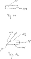
- FIG 8a an embodiment of the cutting knives 37 and 53 is shown in a schematic plan view, which results from a radially outer perspective (cf. 7a and 7b ). Further, the cutting knives 37 and 53 are in Figure 8a shown diametrically opposite in the axial direction, as is the case in the assembled state the connection terminal 11 is the case.
- the cutting knife 37 is designed mirror-symmetrically to the cutting knife 53.
- FIG. 8b the cutting knives 39 and 55 are similar to FIG Figure 8a shown in a schematic plan view, the perspective in contrast to Figure 8a is a radially inner one.
- the cutting blades 39 and 55 are arranged diametrically opposite one another in the axial direction.
- the cutting knife 37 has two cutting edge sections 101 and 103 which enclose an obtuse angle w to one another (here about 165 °).
- the cutting edge sections 101 and 103 are each bevelled, ie the thickness of the cutting knife 37 is reduced in the area of the cutting edge sections 101 and 103.
- the bevelling of the cutting edge sections 101 and 103 is explained in more detail below.
- the cutting knife 39 corresponds to the cutting knife 37, the cutting knife 39 being rotated by 180 ° about its transverse axis.
- the cutting knife 55 corresponds to the cutting knife 53 from Figure 8a , wherein the cutting knife 55 is rotated about its transverse axis by 180 °.
- the cutting knife 55 has cutting edge sections 105 and 107 which enclose an obtuse angle w to one another.
- the cutting edge sections 105 and 107 define a bevel of the cutting knife 55, which is shown in a perspective view in FIG Figure 7b is shown.
- the cutting edge 107 connects an inner jacket surface 109 of the cutting knife 55 to an outer jacket surface 111, the cutting edge 107 with the inner jacket surface 109 forms an obtuse angle g1 and an acute angle g2 with the outer lateral surface 111.
- the cutting edge 107 thus represents a bevel of the cutting knife 55.
- Figure 9a is an in Figure 8a
- the cross section of the cutting knife 37 is shown, which is mirrored twice from the cross section of the cutting contact element 55 Figure 10b corresponds.
- all of the cutting edge sections of the cutting knives 37, 39, 53 and 55 are chamfered in accordance with the cutting edge section 107, each chamfer being oriented radially inward.
- bevel of the cutting edge sections or the size of the angle w different embodiments can also be sought in order to adapt the connection terminal 11, for example, for particularly different types of conductors.
- FIG Figures 9a and 9b Another common embodiment of the cutting knives 37, 39, 53 and 55 is shown in FIG Figures 9a and 9b shown.
- the cutting knives 37 ', 39', 53 'and 55' are characterized by curved cutting edge sections.
- the curved cutting edge section 113 of the cutting knife 37 ', which connects cutting edge sections 101' and 103 'to one another, may be mentioned here as an example.
- a corresponding cutting edge section 106 engages in the axial direction ( Figure 8a ) of the cutting knife 39 diametrically opposite, also tangentially to the insulation of the conductor section 93 (cf. also Figure 5a ).
- the cutting blades 39 and 55 cut into the insulation of the conductor section 93 on opposite sides of the conductor section 93.
- the cutting contact elements 19 and 21 initially retain their axial position due to the pretensioning of the contact spring 23, ie the cutting contact elements 19 and 21 are not pressed axially outward by the insulation of the conductor section 93 via the cutting blades 39 and 55.
- the cutting blades 39 and / or 55 engage the conductor 99 so that electrical contact is made with it.
- the cutting blades 39 and 55 and / or the cutting contact elements 19 and 21 are displaced outward in the axial direction through the conductor 99, the cutting blades 39 and 55 on a further rotation of the actuating element 25 on the conductor 99 slide along.
- the cutting knives 39 and 55 should be safely guided on a circular path.
- the recesses 59 and 65 formed in the coupling disks 29 and 31 guide the relevant cutting knives 39 and 55.
- the disk arms (eg the disk arms 45 and 47) of the cutting contact elements 19 and 21 are, as explained above, by tongues (eg the tongues 61 and 63) supported.
- the cutting knife 39 is supported by the tongue 63 via the disk arm 47, so that the cutting knife 39 is guided radially while cutting into the insulation of the conductor section 93 and can be displaced in the axial direction by the conductor 99 without the entire cutting contact element 19 in is offset in the axial direction.
- the cutting blades 53 and 37 cut diametrically opposite in the radial direction into the insulation of the conductor section 91, with the cutting blades 53 and 37 and / or the cutting contact elements 19 and 21 depending on the thickness of the conductor 97 are offset outward in the axial direction.
- a locking element with a T-shaped cross-section is formed at an outer end of the actuation extension 27 in order to hold the actuation element 25 in the connection position in which one or more insulated conductors are connected to the connection terminal 11.
- the locking element engages in a snap device, not shown, which can be formed, for example, on a component in which the connecting terminal 11 is arranged.
Landscapes
- Details Of Connecting Devices For Male And Female Coupling (AREA)
- Connections Arranged To Contact A Plurality Of Conductors (AREA)
- Cable Accessories (AREA)
- Contacts (AREA)
Description
- Die vorliegende Erfindung betrifft eine Anschlussklemme zum Anschließen eines oder mehrerer isolierter Leiter, umfassend ein Gehäuse mit einer oder mehreren Leiteraufnahmen und eine Kontaktfeder, die ein oder mehrere Schneidkontaktelemente kontaktiert, welche an dem Gehäuse um eine Achse A drehbar gelagert sind. Ein Schneidkontaktelement durchdringt bei einer Drehung um die Achse A zumindest eine Isolierung eines in eine Leiteraufnahme eingeführten Leiterabschnitts und kontaktiert den betreffenden Leiter.
- Derartige Anschlussklemmen zeichnen sich dadurch aus, dass zum Anschließen eines isolierten Leiters der Leiter nicht vorher abisoliert werden muss. Vielmehr sind derartige Anschlussklemmen dazu ausgebildet, ein Trennen der Isolierung und eine Kontaktierung des Leiters in einem Arbeitsschritt zu ermöglichen. Solche "Schneidkontaktklemmen" bieten gegenüber herkömmlichen Anschlussklemmen Vorteile, da isolierte Leiter zeiteffizient und komfortabel an eine solche Anschlussklemme angeschlossen werden können. Verfügbare Schneidkontaktklemmen sind allerdings nur in begrenztem Umfang dafür geeignet, viele verschiedene Arten von isolierten Leitern im Zuge des Anschließens an die Anschlussklemme sicher zu kontaktieren und gleichzeitig eine leichte Bedienung durch den Installateur zu gewährleisten.
-
US 2008/0096415 A1 ,JP 2000 173685 A DE 10 2006 039 799 B3 offenbaren jeweils eine Anschlussklemme, die ähnlich zu der Anschlussklemme der eingangs genannten Art ist. Weitere ähnliche Anschlussklemmen sind inJP H11 54163 A US 3 936 128 A ,DE 692 17 645 T2 undDE 202 05 665 U1 offenbart. - Der Erfindung liegt die Aufgabe zugrunde, eine verbesserte Anschlussklemme der eingangs genannten Art anzugeben.
- Diese Aufgabe wird gemäß einem Aspekt der Erfindung durch eine Anschlussklemme mit den Merkmalen des Anspruchs 1 gelöst, und insbesondere dadurch, dass wenigstens ein Schneidkontaktelement in axialer Richtung versetzbar gelagert ist und zumindest zwei einstückig miteinander verbundene Schneidmesser aufweist, die bei einer Drehung um die Achse A in jeweils eine Leiteraufnahme eindringen, um beide Leiter nur über das Schneidkontaktelement elektrisch leitend direkt miteinander zu verbinden.
- Gemäß einem zweiten Aspekt der Erfindung wird die Aufgabe durch eine Anschlussklemme mit den Merkmalen des Anspruchs 2 gelöst, und insbesondere dadurch, dass wenigstens zwei Schneidkontaktelemente in axialer Richtung versetzbar gelagert sind und jeweils zumindest ein Schneidmesser aufweisen, wobei beide Schneidmesser bei einer Drehung der Schneidkontaktelemente um die Achse A in ein und dieselbe Leiteraufnahme eindringen, um den Leiter von zwei gegenüberliegenden Seiten aus zu kontaktieren.
- Gemäß dem ersten Aspekt der Erfindung werden wenigstens zwei isolierte Leiter elektrisch leitend dadurch miteinander verbunden, dass das wenigstens eine Schneidkontaktelement zwei einstückig miteinander verbundene Schneidmesser aufweist, wobei ein einzelnes Schneidmesser die Isolierung eines zugeordneten Leiterabschnitts durchdringt und den Leiter kontaktiert, wenn das Schneidkontaktelement mit den Schneidmessern um die Achse A gedreht wird. Da die Schneidmesser über das Schneidkontaktelement einstückig miteinander verbunden sind, wird eine direkte elektrische Verbindung ohne Zwischenkontakte zwischen den Leitern hergestellt, wenn eines der Schneidmesser den einen Leiter kontaktiert und das jeweils andere Schneidmesser den anderen Leiter kontaktiert (oder umgekehrt). Die Schneidmesser werden durch die Drehung des Schneidkontaktelements in jeweils eine zugeordnete Leiteraufnahme eingeführt, in welcher jeweils ein (isolierter) Leiterabschnitt aufgenommen ist. Die betreffende Leiterisolierung wird durch das eingeführte Schneidmesser entlang eines Abschnitts durchtrennt und das Schneidmesser kontaktiert den betreffenden Leiter mit zumindest einem Schneidkantenabschnitt, um eine nahezu widerstandslose Verbindung zwischen dem Leiter und dem Schneidkontaktelement herzustellen. Die Schneidmesser und das Schneidkontaktelement sind aus einem elektrisch leitfähigen Material, vorzugsweise einem Metall, gebildet.
- Die einstückige Verbindung der beiden Schneidmesser besitzt den Vorteil, dass die elektrische Verbindung zwischen den beiden Leitern unmittelbar hergestellt wird, d.h. ohne zusätzliche Kontaktstellen. Diese wären zwar grundsätzlich zweckmäßig, um die Schneidmesser z.B. durch punktuelle oder flächige Kontaktierung über Verbindungselemente miteinander zu verwenden. Die entsprechenden Kontaktstellen können allerdings durch Schmutz oder sonstige Beläge, z.B. Oxidationsbeläge, hinsichtlich einer elektrischen Verbindung gestört sein. Beispielsweise kann eine Kontaktstelle als ein ungewünschter elektrischer Widerstand wirken. Im ungünstigsten Fall kann eine Kontaktstelle sogar vollständig gestört sein, so dass überhaupt keine elektrische Verbindung zwischen den zu kontaktieren Teilen hergestellt ist (entsprechend einem sehr hohen oder unendlich hohen Widerstand). Eine solche Fehlfunktion wird durch die einstückig miteinander verbundenen Schneidmesser von vornherein vermieden, wodurch die Zuverlässigkeit der Anschlussklemme insbesondere im Hinblick auf Langlebigkeit verbessert wird.
- Die eingangs erwähnte Kontaktfeder der Anschlussklemme kontaktiert das Schneidkontaktelement und dient als elektrisches Anschlusselement der Anschlussklemme. Insbesondere kann die Kontaktfeder dazu vorgesehen werden, die mit dem Schneidkontaktelement verbundenen Leiter mit elektrischen Kontaktelementen, z.B. einer Steckdose oder eines Verteilers, elektrisch zu verbinden. Vorzugsweise weist die Kontaktfeder zumindest eine Nase auf, welche an dem Schneidkontaktelement angreift, um eine besonders sichere Kontaktierung zu gewährleisten. Zusätzlich oder alternativ kann die Kontaktfeder zumindest abschnittsweise flächig an dem Schneidkontaktelement anliegen.
- Gemäß dem zweiten Aspekt der Erfindung kann die Anschlussklemme zum Anschließen wenigstens eines isolierten Leiters verwendet werden, wobei zunächst der isolierte Leiter mit einem Leiterabschnitt in eine Leiteraufnahme der Anschlussklemme eingeführt wird. Die Anschlussklemme umfasst wenigstens zwei Schneidkontaktelemente, welche vorzugsweise an zwei gegenüberliegenden Seiten der Leiteraufnahme angeordnet und drehbar um die Achse A gelagert sind. Jedes der beiden Schneidkontaktelemente weist zumindest ein Schneidmesser auf. Bei einer gleichzeitigen Drehung der Schneidkontaktelemente um die Achse A dringen die jeweiligen Schneidmesser drehend in die Leiteraufnahme ein und durchtrennen dabei die Isolierung des in die Leiteraufnahme eingeführten Leiterabschnitts und kontaktieren den Leiter von zwei gegenüberliegenden Seiten mit jeweils zumindest einem Schneidkantenabschnitt.
- Die Anschlussklemme erlaubt ein besonders sicheres Kontaktieren des isolierten Leiters, da es zur Kontaktierung des Leiters ausreichend ist, dass eines der Schneidkontaktelemente den Leiter über ein Schneidmesser kontaktiert, d.h. eines der Schneidkontaktelemente dient als "Reserve". Dabei ist zu berücksichtigen, dass beide Schneidkontaktelemente die Kontaktfeder, welche als elektrisches Anschlusselement der Anschlussklemme dienen kann, kontaktieren und eine elektrische Verbindung zu dem Leiter auch dann hergestellt ist, wenn lediglich ein Schneidkontaktelement den Leiter kontaktiert.
- Dass die Isolierung des Leiters von zwei gegenüberliegenden Seiten des Leiters durchtrennt wird, trägt ebenfalls zu einer sicheren Kontaktierung des Leiters bei. Durch die gegenüberliegende Anordnung der Schneidkontaktelemente können sich die Schneidmesser über den Leiterabschnitt gegeneinander abstützen, insbesondere während sie die Leiterisolierung durchtrennen. Der Leiterabschnitt wird zwischen den Schneidmessern eingespannt. Vorteilhafterweise bilden die Schneidmesser mit dem Leiterabschnitt einen Kraftschluss, d.h. eine Kraft, welche von einem Schneidmesser auf den Leiter übertragen wird, wird über den Leiter zumindest teilweise auf das andere Schneidmesser übertragen. Sollte der Leiterabschnitt also z.B. durch die angreifende Kraft eines Schneidmessers insbesondere während des Durchtrennens der Isolierung in der Leiteraufnahme zurück gedrängt werden, so wird der Leiterabschnitt dabei zumindest teilweise in Richtung des zweiten Schneidmessers gedrängt. So kann beispielsweise ein Schneidmesser, welches durch Benutzung zu stumpf geworden ist, um eine Leiterisolierung zu durchtrennen, dennoch dazu beitragen, dass das gegenüberliegende Schneidmesser die Isolierung durchtrennt und den Leiter kontaktiert. Darüber hinaus kann die zur Kontaktierung des Leiters notwendige Kraft durch die wechselseitige Kraftübertragung zwischen den Schneidkontaktelementen und dem Leiterabschnitt reduziert werden, wodurch ein Installateur eine geringere Kraft aufwenden muss, um den Leiter an die Anschlussklemme anzuschließen.
- Ferner wird der angeschlossene Leiter durch die gegenüberliegende Anordnung der Schneidkontaktelemente bzw. Schneidmesser besonders sicher in der Leiteraufnahme fixiert. Bevorzugt schneiden die Schneidmesser entlang eines im Wesentlichen senkrecht zur axialen Erstreckung des Leiterabschnitt definierten Abschnitts in die Leiterisolierung ein, so dass insbesondere eine Verschiebung des Leiterabschnitts in Richtung der axialen Erstreckung des Leiterabschnitt durch die in die Isolierung eingreifenden Schneidmesser blockiert wird. Der angeschlossene Leiter wird hierdurch gegenüber einem unbeabsichtigten Lösen des Leiters von der Anschlussklemme, z.B. durch Ziehen des Leiters, besonders gut gesichert. Beide Aspekte der Erfindung können in einer Anschlussklemme verwirklicht sein. Demgemäß beziehen sich die im Folgenden erläuterten Ausführungsformen auf beide Aspekte, sofern nicht ausdrücklich nur auf einen der Aspekte Bezug genommen wird.
- Gemäß einer vorteilhaften Ausführungsform ist jedes Schneidkontaktelement in axialer Richtung versetzbar gelagert. Durch dieses Merkmal können insbesondere isolierte Leiter unterschiedlicher Dicke an die Anschlussklemme angeschlossen werden, da jedes Schneidkontaktelement in Abhängigkeit von der Isolierungs- und Leiterdicke so versetzt werden kann, dass ein Schneidmesser des Schneidkontaktelements die Leiterisolierung durchtrennt und den Leiter kontaktiert, ohne den Leiter selbst zu beschädigen oder zu durchtrennen. Der Begriff Isolierungsdicke bezieht sich dabei auf den Durchmesser des isolierten Leiters in radialer Richtung. Die Leiterdicke entspricht dem Durchmesser des Leiters. Oftmals kann die Dicke der Isolierung bei Leitertypen mit gleicher Leiterdicke stark variieren, wobei die Isolierungsdicke deutlich größer sein kann als die Leiterdicke. Damit ein Schneidkontaktelement, auch solche dickeren Leiterisolierungen vollständig durchtrennen und den Leiter sicher kontaktieren kann, wird jedes Schneidkontaktelement vorzugsweise gleitend in axialer Richtung gelagert. Die Anschlussklemme ist somit für viele Leitertypen mit verschiedenen Isolierungs- und Leiterdicken universell einsetzbar.
- Gemäß einer bevorzugten Ausführungsform spannt die Kontaktfeder zumindest ein Schneidkontaktelement in axialer Richtung in Richtung zumindest einer Leiteraufnahme vor. Für den Fall, dass das Schneidkontaktelement zumindest zwei Schneidmesser aufweist, welche in jeweils eine zugeordnete Leiteraufnahme eindringen, spannt die Kontaktfeder das betreffende Schneidkontaktelement in axialer Richtung in Richtung der betreffenden Leiteraufnahmen vor. Mit anderen Worten stützt sich das Schneidkontaktelement insbesondere zwischen der Kontaktfeder und der Leiteraufnahme ab, wobei die Vorspannung des Schneidkontaktelements vorzugsweise gewährleistet, dass das Schneidkontaktelement während der Drehung um die Achse A die Isolierung des in die Leiteraufnahme eingeführten Leiterabschnitts durchdringt, ohne dass das Schneidkontaktelement durch den Leiterabschnitt entgegen der Vorspannrichtung in axialer Richtung versetzt wird. Vorzugsweise ist die Vorspannkraft der Kontaktfeder zumindest so groß gewählt, dass das Schneidkontaktelement mit den betreffenden Schneidmessern die Isolierung aller gängigen Leitertypen sicher durchdringen oder durchschneiden kann, ohne dass das betreffende Schneidkontaktelement durch einen Leiterabschnitt versetzt wird.
- Zusätzlich ist die Vorspannkraft der Kontaktfeder vorzugsweise derart gering ausgebildet, dass das Schneidkontaktelement durch den Leiter entgegen der Vorspannrichtung versetzt wird, wenn ein Schneidmesser an den Leiter angreift, d.h. der Leiter wird nicht durch das Schneidmesser beschädigt oder durchtrennt. Darüber hinaus wird so auch eine Beschädigung des Schneidmessers oder sonstiger Teile der Anschlussklemme vermieden. Insgesamt ist die Vorspannkraft der Kontaktfeder vorzugsweise dazu ausgelegt ein möglichst kraftarmes und reibungsloses Anschließen eines isolierten Leiters zu gewährleisten, wobei ein sicheres Durchdringen der Isolierung und Kontaktieren des Leiters einerseits, ein Zurückweichen des betreffendes Schneidkontaktelements bei Angreifen an den Leiter andererseits, sichergestellt wird.
- Für den Fall, dass zwei Schneidkontaktelemente an zwei gegenüberliegenden Seiten einer Leiteraufnahme angeordnet sind, spannt die Kontaktfeder die Schneidkontaktelemente in axialer Richtung gegenläufig in Richtung der betreffenden Leiteraufnahme vor.
- Vorzugsweise umfasst jedes Schneidkontaktelement eine Kontaktscheibe, wobei sich zumindest ein Schneidmesser in axialer Richtung weg von der Kontaktscheibe erstreckt und elektrisch leitend mit ihr verbunden ist. Mit anderen Worten ist jedes Schneidmesser an einem Schneidkontaktelement parallel zu der Achse A ausgerichtet, wodurch bei einer Drehbewegung des Schneidkontaktelements um die Achse A ein kraftarmes Durchdringen der Leiterisolierung durch das betreffende Schneidmesser ermöglicht wird. Vorzugsweise weist jedes Schneidmesser zumindest einen Schneidkantenabschnitt auf, der in Richtung einer zugeordneten Leiteraufnahme ausgerichtet ist.
- Darüber hinaus ist jedes Schneidmesser bevorzugt als Segment einer Zylindermantelfläche ausgebildet. Ein derart ausgebildetes Schneidmesser ist an einem Schneidkontaktelement vorzugsweise so angeordnet, dass die Zylinderachse der Zylindermantelfläche koaxial zu der Achse A verläuft. Mit anderen Worten ist das Schneidmesser um die Achse A gekrümmt. Das Schneidmesser kann bei einer Drehung des Schneidkontaktelements um die Achse A somit besonders kraftarm eine Leiterisolierung durchschneiden.
- Gemäß einer weiteren Ausführungsform sind zwei an einem Schneidkontaktelement vorgesehene Schneidmesser in radialer Richtung diametral gegenüberliegend angeordnet. Hierdurch wird ein Verkanten des Schneidkontaktelements verhindert, wenn das Schneidkontaktelement bei einer Drehung um die Achse A mit den Schneidmessern zwei Leiterisolierungen durchdringt. Ein Verkanten wird durch Verkippen oder Verdrehen des Schneidkontaktelements aus einer Bezugsebene verursacht, welche sich vorzugsweise senkrecht zur Achse A erstreckt. Durch das Verkippen oder Verdrehen aus der Bezugsebene könnte ansonsten das Schneidkontaktelement beispielsweise in dem Gehäuse verkanten, wodurch die Drehung des Schneidkontaktelements behindert oder blockiert wird. Die Schneidmesser erstrecken sich bevorzugt senkrecht zu der Bezugsebene und sind um die Achse A diametral gegenüberliegend, d.h. achsensymmetrisch angeordnet.
- Gemäß einer bevorzugten Ausführungsform weist ein Schneidmesser zumindest zwei gerade Schneidkantenabschnitte auf, die zueinander einen stumpfen Winkel einschließen oder durch einen gekrümmten Schneidkantenabschnitt miteinander verbunden sind. Durch dieses Merkmal wird erreicht, dass bei einer Drehung des Schneidmessers die Isolierung des betreffenden Leiterabschnitts tangential aufgetrennt wird. Vorzugsweise greift eine der beiden geraden Schneidkantenabschnitte tangential an der Leiterisolierung an und wird entlang einer Kreisbahn um die Achse A durch die Isolierung des Leiters geführt, wobei das Schneidmesser die Isolierung durch ziehenden oder drückenden Schnitt auftrennt. Die tangential angreifende Schneidkante besitzt den Vorteil, dass die Leiterisolierung bei überwiegend gleichbleibendem Kraftaufwand gleichmäßig durchtrennt wird. Hierdurch kann dem Installateur bei einer Drehung des Schneidkontaktelements ein angenehmes gleichförmiges taktiles Feedback zur Verfügung gestellt werden, d.h. ein ungleichmäßiger und ggf. irritierender Kraftaufwand wird bei der Drehung des Schneidkontaktelements vermieden.
- Der tangential angreifende Schneidkantenabschnitt besitzt auch den Vorteil, dass der Schneidkantenabschnitt nach Durchdringen der Isolierung auch tangential an den von der Leiterisolierung umschlossenen Leiter angreift. Das betreffende Schneidmesser kann somit besonders gut durch den Leiter versetzt werden und an dem Leiter entlanggleiten kann, ohne diesen zu beschädigen oder zu durchtrennen.
- Der Leiterabschnitt ist vorzugsweise ortsfest in der Leiteraufnahme angeordnet, so dass das Schneidmesser durch einen ersten an dem Leiter entlanggleitende gerade Schneidkantenabschnitt so weit entgegen der Vorspannrichtung des Schneidkontaktelements in axialer Richtung versetzt wird, bis das Schneidmesser den Leiter bei einer Drehung passiert und ein zweiter Schneidkantenabschnitt an dem Leiter entlanggleitet und diesen kontaktiert.
- Gemäß einer bevorzugten Ausführungsform erstrecken sich zwei Leiteraufnahmen in einer senkrecht zu der Achse A liegenden Ebene durch das Gehäuse. Mit anderen Worten sind die Leiteraufnahmen senkrecht zu der Achse A übereinander angeordnet, wodurch eine kompakte Bauweise der Anschlussklemme gewährleistet wird.
- Das Gehäuse und/oder eine Leiteraufnahme weisen zumindest einen seitlichen Durchgriffsabschnitt auf, der einen Drehbereich eines Schneidkontaktelements begrenzt. Durch die Begrenzung des Drehbereichs können zwei Anschläge für das Schneidkontaktelement definiert werden, um das Anschließen eines isolierten Leiters an die Anschlussklemme zu erleichtern. Der Drehbereich wird vorzugsweise so festgelegt, dass das Schneidkontaktelement zwischen einer Anschlussstellung und einer Freigabestellung gedreht werden kann. In der Anschlussstellung durchdringt zumindest ein Schneidmesser eines Schneidkontaktelements eine Leiterisolierung eines in die Leiteraufnahme eingeführten Leiterabschnitts und kontaktiert den Leiter. Zudem ist der Leiterabschnitt in der Leiteraufnahme durch das Schneidmesser des Schneidkontaktelements fixiert. In der Freigabestellung ist die mechanische und elektrische Verbindung (Kontaktierung) zwischen dem Schneidkontaktelement und dem Leiter gelöst und ein Leiterabschnitt kann in die Leiteraufnahme eingeführt bzw. aus ihr entfernt werden.
- Gemäß einer bevorzugten Ausführungsform weist ein Schneidkontaktelement zumindest einen Einschnitt auf, der eine voneinander entkoppelte Axialbewegung des Schneidmessers oder der Schneidmesser ermöglicht. Mit anderen Worten vergrößert ein solcher Einschnitt die axiale Bewegbarkeit eines Schneidmessers relativ zu dem Schneidkontaktelement, wodurch insbesondere auch die axiale Bewegbarkeit zweier an einem Schneidkontaktelement ausgebildeter Schneidmesser erhöht wird. Zur weiteren Vergrößerung dieser Beweglichkeit können auch mehrere Einschnitte an dem Schneidkontaktelement vorgesehen werden. Ein Vorteil dieser Entkopplung besteht darin, dass eine Anpassung der Axialposition eines Schneidmessers in Abhängigkeit von der Dicke eines eingeführten Leiterabschnitts unabhängig von einer Axialbewegung des Schneidkontaktelements erfolgen kann, wodurch insbesondere ein unerwünschtes Verkanten oder Verkippen des Schneidkontaktelements verhindert werden kann.
- Bevorzugt ist ein Schneidmesser flexibel mit der Kontaktscheibe eines Schneidkontaktelements verbunden. Somit kann das betreffende Schneidmesser in Abhängigkeit von den Abmessungen und Eigenschaften des eingeführten Leiterabschnitts im Wesentlichen entkoppelt von der Kontaktscheibe in axialer Richtung und/oder radialer Richtung bewegt werden. Dies gewährleistet insbesondere eine zuverlässige Kontaktierung des Leiters und wirkt einem Verkanten oder Verkippen des Schneidkontaktelements entgegen.
- Gemäß einer vorteilhaften Ausführungsform ist zur Drehung des Schneidkontaktelements oder der Schneidkontaktelemente ein Betätigungselement vorgesehen, wobei das Betätigungselement eine oder mehrere Koppelscheiben sowie einen Betätigungsfortsatz umfasst, und wobei das Betätigungselement über eine Koppelscheibe form- und/oder kraftschlüssig und/oder drehfest mit einem Schneidkontaktelement koppelbar ist. Ein solches Betätigungselement ermöglicht es einem Benutzer der Anschlussklemme das eine oder die mehreren Schneidkontaktelemente ohne Verwendung zusätzlicher Werkzeuge um die Achse A zu drehen, um einen oder mehrere isolierte Leiter an die Anschlussklemme anzuschließen. Der Betätigungsfortsatz erstreckt sich beispielsweise in tangentialer, radialer oder axialer Richtung weg von der einen oder den mehreren Koppelscheiben. Vorzugsweise greift ein einzelner Betätigungsfortsatz an der einen oder den mehreren Koppelscheiben an, wobei auch mehrere Betätigungsfortsätze vorgesehen sein können, z.B. ein Betätigungsfortsatz pro Koppelscheibe. Für den Fall, dass die Anschlussklemme zwei Schneidkontaktelemente umfasst, ist vorzugsweise ein Betätigungselement für beide Schneidkontaktelemente vorgesehen, um die Schneidkontaktelemente gleichzeitig, d.h. synchron drehen zu können. Die Schneidkontaktelemente können dabei bezüglich einer Drehung um die Achse A gleichartig ausgerichtet sein oder es kann ein Winkelversatz bzw. Drehversatz zwischen den Schneidkontaktelementen vorgesehen werden.
- Eine gleichzeitige Drehung der beiden Schneidkontaktelemente mit Hilfe eines Betätigungselements oder Betätigungsfortsatzes erlaubt ein effizientes Anschließen von isolierten Leitern an die Anschlussklemme, da die beiden Schneidkontaktelemente nicht separat gedreht werden müssen. Zum anderen erlaubt ein gleichzeitiges Drehen der Schneidkontaktelemente ein besonders sicheres Anschließen zumindest eines isolierten Leiters an die Anschlussklemme, wenn die an jeweils einem Schneidkontaktelement vorgesehenen Schneidmesser in axialer Richtung diametral gegenüberliegend angeordnet sind und diese Anordnung durch eine Drehung der Schneidkontaktelemente nicht verändert wird. Insbesondere können die Schneidmesser die Isolierung eines eingeführten Leiterabschnitts gleichzeitig von zwei gegenüberliegenden Seiten aus durchdringen und den Leiter kontaktieren, wobei der Leiterabschnitt zangenartig zwischen den beiden Schneidmessern eingeklemmt wird.
- Bevorzugt weist jede Koppelscheibe eine Ausnehmung zur Kopplung eines Schneidkontaktelements auf, wobei die Ausnehmung eine radiale Führung für ein oder mehrere Schneidmesser des aufgenommenen Schneidkontaktelements und/oder eine axiale Führung für das Schneidkontaktelement bildet und/oder ein Verwinden des Schneidkontaktelements begrenzt, wenn das Schneidkontaktelement in der Ausnehmung aufgenommen ist. Mit anderen Worten dient die Ausnehmung zur Aufnahme eines Schneidkontaktelements, wobei die Ausnehmung die an dem aufgenommenen Schneidkontaktelement ausgebildeten Schneidmesser in radialer Richtung führt. Hierdurch wird insbesondere gewährleistet, dass das oder die Schneidmesser bei einer Drehung des Schneidkontaktelements um die Achse A auf einer Kreisbahn geführt werden, ohne dass die Schneidmesser in radialer Richtung "wegbiegen". Ein solches Wegbiegen soll insbesondere dann verhindert werden, wenn die Schneidmesser in eine zugeordnete Leiterisolierung einschneiden. Darüber hinaus wird durch die Ausnehmung ein unerwünschtes Verwinden eines Schneidkontaktelements begrenzt, wodurch ein Verkanten oder Verklemmen des Schneidkontaktelements oder von Teilen des Schneidkontaktelements entgegengewirkt wird. Hierbei trägt auch die axiale Führung des Schneidkontaktelements durch die Ausnehmung bei. Dies verbessert die Haltbarkeit und zuverlässige Funktionsweise der Anschlussklemme.
- Vorzugsweise erstreckt sich zumindest eine Zunge der Koppelscheibe in die Ausnehmung, wobei die Zunge eine mit einem Einschnitt des Schneidkontaktelements korrespondiere Form besitzt. Die Zunge kann dabei vorzugsweise um die Achse A gekrümmt sein, so dass eine Innenkante des Einschnitts im Wesentlichen senkrecht zur radialen Richtung an der betreffenden Außenkante der Zunge angreift. Hierdurch wird eine besonders gleichmäßige und sichere radiale Führung des oder der mehreren Schneidmesser gewährleistet. Darüber hinaus verbessert die Zunge die axiale Führung des Schneidkontaktelements.
- Gemäß einer weiteren Ausführungsform umfasst die Kontaktfeder zumindest zwei Federarme, die an beabstandeten Abschnitten an einem Schneidkontaktelement angreifen und es in axialer Richtung vorspannen. Hierdurch kann insbesondere ein Verkanten und eine daraus resultierende Blockierung des Schneidkontaktelements vermieden werden, weil Kippbewegungen des Schneidkontaktelements aus einer senkrecht zur Achse A liegenden Ebene (Bezugsebene) durch die an beabstandeten Abschnitten angreifenden Federarme unmittelbar kompensiert werden.
- Vorzugsweise umfasst die Kontaktfeder zumindest zwei Federarme, die zwei an einem Schneidkontaktelement vorgesehene Schneidmesser unabhängig voneinander in axialer Richtung vorspannen. Dieses Merkmal besitzt den Vorteil, dass zwei Leiterabschnitte, welche jeweils in eine zugeordnete Leiteraufnahme aufgenommen sind, sich im Durchmesser deutlich unterscheiden können, ohne dass das Schneidkontaktelement zum Anschließen der Leiter an die Anschlussklemme in der Bezugsebene verkippt werden muss. Die zwei Federarme spannen die Schneidmesser insbesondere in Abhängigkeit von den Leiter- und Isolierungseigenschaften in axialer Richtung vor, ohne das jeweils andere Schneidmesser in unerwünschter Weise zu beeinflussen.
- Gemäß einer weiteren Ausführungsform umfasst die Kontaktfeder zumindest einen Federarm, der ein an einem Schneidkontaktelement vorgesehenes Schneidmesser in axialer Richtung im Wesentlichen unabhängig von der Kontaktscheibe vorspannt.
- Vorzugsweise umgreift die Kontaktfeder das Schneidkontaktelement oder die Schneidkontaktelemente, wobei die Kontaktfeder insbesondere zusätzlich das Gehäuse und/oder die Leiteraufnahme/Leiteraufnahmen umgreift. Die Kontaktfeder kann beispielsweise als eine U-förmige Feder ausgebildet sein. Für den Fall einer Anschlussklemme mit einem einzelnen Schneidkontaktelement umgreift die Kontaktfeder das Schneidkontaktelement und das Gehäuse und spannt das Schneidkontaktelement in axialer Richtung in Richtung des Gehäuses vor. Für den Fall, dass zwei Schneidkontaktelemente vorgesehen sind, umgreift die Kontaktfeder die beiden Schneidkontaktelemente und spannt sie in axialer Richtung in gegensätzlichen Richtungen in Richtung des Gehäuses bzw. der Leiteraufnahmen vor. Die Leiteraufnahmen sind vorzugsweise integral, d.h. einstückig an dem Gehäuse ausgebildet. Sofern die Leiteraufnahmen separat von dem Gehäuse ausgebildet und mit dem Gehäuse verbunden sind, spannt die Kontaktfeder das Schneidkontaktelement oder die Schneidkontaktelemente durch Umgreifen in Richtung der Leiteraufnahmen vor.
- Darüber hinaus umgreift die Kontaktfeder vorzugsweise das Betätigungselement. Hierdurch wird vermieden, dass das Betätigungselement bei einer Drehung um die Achse A sich von den mit dem Betätigungselement gekoppelten Schneidkontaktelementen lösen kann, in dem z.B. die Koppelscheibe aus der Kontaktscheibe des Schneidkontaktelements herausrutscht. Die Kontaktfeder gewährleistet somit eine sichere Kopplung zwischen dem Betätigungselement und den Schneidkontaktelementen, welche mit dem Betätigungselement gekoppelt sind.
- Gemäß einer weiteren bevorzugten Ausführungsform weist das Betätigungselement zwei voneinander beabstandete Koppelscheiben auf, welche einen Zwischenraum für die Leiteraufnahme/Leiteraufnahmen bilden. Durch dieses Merkmal kann die Anschlussklemme besonders kompakt ausgebildet sein. Dies ermöglicht insbesondere einen platzsparenden Einsatz der Anschlussklemme, beispielsweise in Steckdosen oder Verteilereinheiten.
- Vorteilhafte Ausführungsformen der Erfindung sind auch in den Unteransprüchen, der Beschreibung und den Zeichnungen angegeben.
- Die Erfindung wird im Folgenden beispielhaft unter Bezugnahme auf die Zeichnungen beschrieben.
- Es zeigen:
- Fig. 1a
- eine Perspektivansicht einer Anschlussklemme in einem geöffneten Zustand,
- Fig. 1b
- eine Perspektivansicht der Anschlussklemme von
Fig. 1a in einem geschlossenen Zustand, - Fig. 2
- eine Explosionsansicht der Anschlussklemme von
Fig. 1a , - Fig. 3
- eine Perspektivansicht eines Betätigungselements der Anschlussklemme von
Fig. 1a , - Fig. 4
- eine perspektivische Schnittansicht der Anschlussklemme von
Fig. 1a , - Fig. 5a
- eine perspektivische Schnittansicht der Anschlussklemme von
Fig. 4 in einem geöffneten Zustand, wobei isolierte Leiterabschnitte in die Anschlussklemme eingeführt sind, - Fig. 5b
- eine perspektivische Schnittansicht der Anschlussklemme von
Fig. 5a in einem geschlossenen Zustand, wobei Leiterabschnitte in die Anschlussklemme eingeführt sind, - Fig. 6a
- eine Perspektivansicht einer Anschlussklemme ohne Kontaktfeder in einem geöffneten Zustand,
- Fig. 6b
- eine Perspektivansicht der Anschlussklemme von
Fig. 6a in einem geschlossenen Zustand, - Fig. 7a und 7b
- Perspektivansichten zweier Schneidkontaktelemente einer Anschlussklemme,
- Fig. 8a und 8b
- Draufsichten von Schneidmessern von Schneidkontaktelementen einer Anschlussklemme,
- Fig. 9a und 9b
- Draufsichten von alternativen Schneidmessern von Schneidkontaktelementen einer Anschlussklemme,
- Fig. 10a und 10b
- Querschnittansichten von Schneidmessern von
Fig. 8a und 8b . - Der Aufbau einer Anschlussklemme 11 wird zunächst anhand von
Fig. 1a, 1b und2 erläutert. Die Anschlussklemme 11 umfasst ein Gehäuse 13 mit integral ausgebildeten Leiteraufnahmen 15 und 17, eine Kontaktfeder 23, ein Betätigungselement 25 sowie Schneidkontaktelemente 19 und 21. Das Gehäuse 13 und das Betätigungselement 25 sind aus Kunststoff gefertigt. Die Kontaktfeder 23 und die Schneidkontaktelemente sind aus Metall gebildet und elektrisch leitend. - Das Betätigungselement 25 umfasst einen Betätigungsfortsatz 27, welcher sich von zwei Koppelscheiben 29 und 31 in eine tangentiale Richtung weg von den Koppelscheiben 29 und 31 erstreckt. Die Koppelscheiben 29 und 31 sind voneinander beabstandet angeordnet und bilden einen Zwischenraum 33.
- Die Schneidkontaktelemente 19 und 21 sind bei der gezeigten Ausführungsform spiegelsymmetrisch ausgebildet, wobei im Folgenden das Schneidkontaktelement 19 im Detail beschrieben wird. Das Schneidkontaktelement 19 weist eine Kontaktscheibe 35 auf, die als Segment einer kreisförmigen Scheibe gebildet ist. Zwei Schneidmesser 37 und 39 erstrecken sich diametral gegenüberliegend von einer Außenkante der Kontaktscheibe 35 senkrecht zur Scheibenebene weg von der Kontaktscheibe 35.
- Das Schneidkontaktelement 19 ist in
Fig. 7a in einer vergrößerten Perspektivansicht gezeigt. In der Kontaktscheibe 35 sind gekrümmte, zungenförmige Einschnitte 41 und 43 gebildet, durch die zwei Scheibenarme 45 und 47 an der Kontaktscheibe 35 gebildet sind. Das Schneidmesser 37 ist einstückig an dem Scheibenarm 45 ausgebildet und über einen Steg 49 mit der Kontaktscheibe 35 verbunden. Das Schneidmesser 39 ist einstückig an dem Scheibenarm 47 gebildet und über einen Steg 51 mit der Kontaktscheibe 35 verbunden. - In
Fig. 7b ist das spiegelsymmetrisch ausgebildete Schneidkontaktelement 21 gezeigt, wobei sich Schneidmesser 53 und 55 von der Innenseite einer Kontaktscheibe 57 senkrecht zu der Scheibenebene weg von der Kontaktscheibe 37 erstrecken. In dem Schneidkontaktelement 21 sind Einschnitte 42 und 44 gebildet. - Das Betätigungselement 25 ist in
Fig. 3 in einer vergrößerten Perspektivansicht gezeigt. In der Koppelscheibe 29 ist eine Ausnehmung 59 zur formschlüssigen und drehfesten Aufnahme des Schneidkontaktelements 19 gebildet. Von der Koppelscheibe 29 erstrecken sich Zungen 61 und 63 in die Ausnehmung 59. Die Zunge 61 besitzt eine zu dem Einschnitt 41 des Schneidkontaktelements 19 komplementäre Form. In entsprechender Weise besitzt die Zunge 63 eine zu dem Einschnitt 43 des Schneidkontaktelements 19 komplementäre Form. Die Koppelscheibe 31 weist eine Ausnehmung 65 zur formschlüssigen Aufnahme des Schneidkontaktelements 21 auf, wobei sich Zungen (nicht gezeigt) spiegelsymmetrisch zu der Koppelscheibe 29 in die Ausnehmung 65 erstrecken, welche mit den Einschnitten 42 und 44 des Schneidkontaktelements 21 korrespondieren. - In
Fig. 1a ist die Anschlussklemme 11 in einem montierten und geöffneten Zustand gezeigt. Das Betätigungselement 25 ist an dem Gehäuse 13 um eine Achse A drehbar gelagert (vgl. auchFig. 2 ). Hierbei sind die integral an dem Gehäuse 13 ausgebildeten Leiteraufnahmen 15 und 17 in dem Zwischenraum 33 des Betätigungselements 25 angeordnet. Das Schneidkontaktelement 19 ist in die Ausnehmung 59 der Koppelscheibe 29 aufgenommen, wobei die Zunge 61 in dem Einschnitt 41 eingeführt ist und die Zunge 63 in den Einschnitt 43 eingeführt ist. Das Schneidmesser 37 ist durch einen am Gehäuse 13 ausgebildeten Durchgriffsabschnitt 67 geführt (vgl.Fig. 2 ). In entsprechender Weise ist das Schneidmesser 39 durch einen Durchgriffsabschnitt 69 geführt. An der in axialer Richtung diametral gegenüberliegenden Seite der Anschlussklemme 11 ist das Schneidkontaktelement 21 in der Ausnehmung 65 der Koppelscheibe 31 aufgenommen, wobei die Schneidmesser 53 und 55 durch Durchgriffsabschnitte (nicht gezeigt) an dem Gehäuse 13 geführt sind, welche spiegelsymmetrisch zu den Durchgriffsabschnitten 67 und 69 an der in axialer Richtung gegenüberliegenden Seite des Gehäuses 13 ausgebildet sind. - Die Kontaktfeder 23 umfasst vier Federarme 71, 73, 75 und 77, welche in
Fig. 2 gezeigt sind. Die Kontaktfeder 23 ist einstückig ausgebildet, d.h. sämtliche Federarme 71, 73, 75 und 77 sind integral an der Kontaktfeder 23 ausgebildet. Ferner weisen die Federarme 71, 73, 75 und 77 elastische Eigenschaften auf. Im montierten Zustand der Anschlussklemme 11 (vgl. z.B.Fig. 1a ) umgreift die Kontaktfeder 23 die Koppelscheiben 29 und 31 sowie die in den jeweiligen Ausnehmungen 59 und 65 aufgenommenen Schneidkontaktelemente 19 und 21. - Die Kontaktfeder 23 spannt das Schneidkontaktelement 19 an beabstandeten Abschnitten der Kontaktscheibe 35 des Schneidkontaktelements 19 in axialer Richtung in Richtung der Leiteraufnahmen 15 und 17 vor. Im geöffneten Zustand der Anschlussklemme 11 (
Fig. 1a ) greift der Federarm 71 der Kontaktfeder 23 über eine Nase 79 (Fig. 2 ) an den Steg 51 der Kontaktscheibe 35 an (vgl. auchFig. 7a ). Auf der in axialer Richtung diametral gegenüberliegenden Seite greift der Federarm 73 über eine Nase 81 an die Kontaktscheibe 57 des Schneidkontaktelements 21 an und spannt das Schneidkontaktelement 21 in axialer Richtung vor. Die Federarme 71 und 73 spannen die Schneidkontaktelemente 19 und 21 somit in axialer Richtung in gegenläufige Richtungen vor. Der Federarm 75 der Kontaktfeder 23 spannt das Schneidkontaktelement 19 in axialer Richtung vor, wobei der Federarm 75 über eine Nase 83 an den Steg 49 der Kontaktscheibe 35 des Schneidkontaktelements 19 angreift. In entsprechender Weise spannt der Federarm 77 der Kontaktfeder 23 das Schneidkontaktelement 21 über eine Nase 85 in axial gegenläufiger Richtung vor. - Die Kontaktfeder 23 ist über die Federarme 71, 73, 75, 77 elektrisch mit den Schneidkontaktelementen 19 und 21 verbunden, wobei die elektrische Kontaktiearung über die betreffenden Nasen 79, 81, 83 und 85 unabhängig von der Drehstellung der Schneidkontaktelemente 19 und 21 hergestellt ist. Da die Kontaktscheibe 35, die Stege 49, 51, die Scheibenarme 45, 47 sowie die Schneidmesser 37, 39 integral an dem Schneidkontaktelement 19 ausgebildet sind, befinden sich sämtliche Teile des Schneidkontaktelements 19 stets auf demselben elektrischen Potential. Über die Nasen 79, 83 der Federarme 71, 75 wird das Schneidkontaktelement 19 somit doppelt und bezüglich sämtlicher Teile des Schneidkontaktelements 19 elektrisch besonders sicher kontaktiert. In entsprechender Weise wird das Schneidkontaktelement 21 über die Nasen 81, 85 der Federarme 73, 77 doppelt und vollständig kontaktiert. Da die Kontaktfeder 23 integral ausgebildet ist, sind auch die Schneidkontaktelemente 19 und 21 stets elektrisch miteinander verbunden.
- Zum Anschließen einer oder mehrerer isolierter Leiter an die Anschlussklemme 11 wird das Betätigungselement 25 durch manuelle Betätigung des Betätigungsfortsatzes 27 um die Achse A ausgehend von der in
Fig. 1a gezeigten Drehstellung in mathematisch positiver Richtung gedreht, bis das Betätigungselement 25 die inFig. 1b gezeigte Drehstellung aufweist. Sobald das Betätigungselement 25 aus der inFig. 1a gezeigten Drehstellung in die inFig. 1b gezeigte Anschlussstellung gedreht wird, greift der Federarm 71 der Kontaktfeder 23 über die Nase 79 an den Scheibenarm 47 des Schneidkontaktelements 19 an und spannt hierdurch das Schneidmesser 39 in axialer Richtung in Richtung der Leiteraufnahme 17 vor. Ferner greift der Federarm 75 der Kontaktfeder 23 über die Nase 83 an den Scheibenarm 45 an und spannt das Schneidmesser 37 in Richtung der Leiteraufnahme 15 vor. In entsprechender Weise werden die Schneidmesser 53 und 55 des Schneidkontaktelements 21 durch die Federarme 73 und 77 der Kontaktfeder 23 in Richtung der Leiteraufnahmen 15 und 17 vorgespannt. - Im Folgenden wird nun die Funktionsweise der Anschlussklemme 11 näher erläutert. Hierzu zeigen
Fig. 4 ,5a und 5b jeweils Schnittansichten der Anschlussklemme 11, anhand derer das Anschließen isolierter Leiter beschrieben wird. InFig. 4 ist die Anschlussklemme 11 im geschlossenen Zustand gezeigt, wobei die Schnittebene senkrecht zur Achse A durch die Leiteraufnahmen 15 und 17 verläuft. Das Schneidmesser 53 des Schneidkontaktelements 21 greift rückseitig in die Leiteraufnahme 15 ein und das Schneidmesser 55 des Schneidkontaktelements 21 greift rückseitig in die Leiteraufnahme 17 ein. - In
Fig. 5a ist die Anschlussklemme 11 entsprechend zuFig. 1a im geöffneten Zustand gezeigt, wobei die Schnittebene durch die Anschlussklemme 11 im Vergleich zuFig. 4 geringfügig in axialer Richtung rückversetzt ist, so dass nun die Schneidmesser 37 und 39 des Schneidkontaktelements 19 ebenfalls gezeigt sind. Ein isolierter Leiter 87, welcher inFig. 5a nur teilweise gezeigt ist, ist mit einem Leiterabschnitt 91 in die Leiteraufnahme 15 eingeführt. Ein weiterer isolierter Leiter 89 ist mit einem Leiterabschnitt 93 in die Leiteraufnahme 17 eingeführt. Der Leiterabschnitt 91 kann sowohl von einer Vorderseite der Anschlussklemme 11 aus in die Leiteraufnahme 15 oder von einer Rückseite der Anschlussklemme 11 durch eine in der Kontaktfeder 23 gebildete Öffnung 95 (Fig. 4 ) in die Leiteraufnahme 15 eingeführt werden. Das Betätigungselement 25 befindet sich inFig. 5a in einer Freigabestellung, in der keines der Schneidmesser 37, 39, 53 und 55 in eine der Leiteraufnahmen 15 und 17 eingreift. Die Leiterabschnitte 91 und 93 können somit in die Leiteraufnahmen 15 und 17 wahlweise eingeführt und herausgeführt werden. - In
Fig. 5b ist die Anschlussklemme 11 entsprechend zuFig. 1b im geschlossenen Zustand gezeigt, wobei die Schnittebene derjenigen ausFig. 5a entspricht. Im Vergleich zuFig. 5a sind inFig. 5b allerdings lediglich die Leiter 97 und 99 gezeigt, d.h. der Leiter 97 entspricht dem isolierten Leiter 87 und der Leiter 99 entspricht dem isolierten Leiter 89, wobei die entsprechenden Isolierungen nicht sichtbar sind. Wie ausFig. 5b ersichtlich, kontaktiert das Schneidmesser 39 den Leiter 99 und das Schneidmesser 37 kontaktiert den Leiter 97. Da die Schneidmesser 39 und 37 über die Kontaktscheibe 35 einstückig miteinander verbunden sind, sind nun die Leiter 97 und 99 direkt elektrisch leitend miteinander verbunden (vgl.Fig. 1b undFig. 2 ). Ferner kontaktiert inFig. 5b das Schneidmesser 55 den Leiter 99 und das Schneidmesser 53 kontaktiert den Leiter 97. Hierbei sind die Schneidmesser 55 und 53 entsprechend über die Kontaktscheibe 57 des Schneidkontaktelements 21 einstückig miteinander verbunden, wodurch die Leiter 97 und 99 elektrisch leitend direkt miteinander verbunden sind. - Der Leiter 99 wird durch die erläuterte Vorspannung der Federarme 71 und 73 zwischen den Schneidmessern 39 und 55 eingeklemmt, so dass der Leiter 99 besonders sicher kontaktiert wird und in der Leiteraufnahme 17 fixiert ist. In entsprechender Weise ist der Leiter 97 durch die erläuterte Vorspannung durch die Federarme 75 und 77 zwischen den Schneidmessern 37 und 53 eingeklemmt, so dass der Leiter 97 besonders sicher kontaktiert wird und in der Leiteraufnahme 15 fixiert wird.
- Die Kontaktfeder 23 kontaktiert über die Nasen 79, 81, 83, 85 der Federarme 71, 75, 73, 77 beide Schneidkontaktelemente 19 und 21, so dass beide Leiter 97, 99 jeweils doppelt mit der Kontaktfeder 23 elektrisch leitend verbunden sind. Mittels der Kontaktfeder 23 können weitere elektrische Leiter vorteilhaft an die Anschlussklemme 11 angeschlossen werden.
- Im Folgenden wird das Durchdringen der Isolierungen der isolierten Leiter 87 und 89 näher erläutert. Hierzu wird zunächst die Ausbildung der Schneidmesser 37, 39, 53 und 55 beschrieben.
- In
Fig. 8a ist eine Ausführungsform der Schneidmesser 37 und 53 in einer schematischen Draufsicht gezeigt, die sich aus einer radial äußeren Perspektive ergibt (vgl.Fig. 7a und 7b ). Ferner sind die Schneidmesser 37 und 53 inFig. 8a in axialer Richtung diametral gegenüberliegend gezeigt, wie dies im montierten Zustand der Anschlussklemme 11 der Fall ist. Das Schneidmesser 37 ist spiegelsymmetrisch zu dem Schneidmesser 53 ausgebildet. - In
Fig. 8b sind die Schneidmesser 39 und 55 ähnlich wie inFig. 8a in einer schematischen Draufsicht gezeigt, wobei die Perspektive im Gegensatz zuFig. 8a eine radial innen liegende ist. Die Schneidmesser 39 und 55 sind wie im montierten Zustand der Anschlussklemme 11 in axialer Richtung diametral gegenüberliegend angeordnet. - Die grundsätzliche Topologie der Schneidmesser 37, 53, 39, 55 wird nun beispielhaft anhand des Schneidmessers 37 beschrieben.
- Das Schneidmesser 37 weist zwei Schneidkantenabschnitte 101 und 103 auf, welche einen stumpfen Winkel w zueinander einschließen (hier etwa 165°). Die Schneidkantenabschnitte 101 und 103 sind jeweils angeschrägt ausgebildet, d.h. die Dicke des Schneidmessers 37 verringert sich im Bereich der Schneidkantenabschnitte 101 und 103. Die Anschrägung der Schneidkantenabschnitte 101 und 103 wird im Folgenden noch näher erläutert. Das Schneidmesser 39 entspricht dem Schneidmesser 37, wobei das Schneidmesser 39 um seine Querachse um 180° gedreht ist. Das Schneidmesser 55 entspricht dem Schneidmesser 53 aus
Fig. 8a , wobei das Schneidmesser 55 um seine Querachse um 180° gedreht ist. Das Schneidmesser 55 weist Schneidkantenabschnitte 105 und 107 auf, die zueinander einen stumpfen Winkel w einschließen. - Die Schneidkantenabschnitte 105 und 107 definieren eine Anschrägung des Schneidmessers 55, welche in perspektivischer Ansicht in
Fig. 7b gezeigt ist. Genauer ist die Anschrägung inFig. 10b gezeigt, welche einen inFig. 8b gekennzeichneten Querschnitt des Schneidmessers 55 beschreibt. Die Schneidkante 107 verbindet eine innere Mantelfläche 109 des Schneidmessers 55 mit einer äußeren Mantelfläche 111, wobei die Schneidkante 107 mit der inneren Mantelfläche 109 einen stumpfen Winkel g1 und mit der äußeren Mantelfläche 111 einen spitzen Winkel g2 einschließt. Die Schneidkante 107 stellt somit eine Anschrägung des Schneidmessers 55 dar. InFig. 9a ist ein inFig. 8a gekennzeichneter Querschnitt des Schneidmessers 37 gezeigt, welcher doppelt gespiegelt dem Querschnitt des Schneidkontaktelements 55 ausFig. 10b entspricht. - In der hier beschriebenen Ausführungsform sind sämtliche Schneidkantenabschnitte der Schneidmesser 37, 39, 53 und 55 entsprechend dem Schneidkantenabschnitt 107 angeschrägt, wobei jeder Anschrägung radial nach innen ausgerichtet ist. Bezüglich der Anschrägung der Schneidkantenabschnitte oder der Größe des Winkels w können aber auch unterschiedliche Ausführungsformen angestrebt werden, um die Anschlussklemme 11 beispielsweise für besonders unterschiedliche Leitertypen anzupassen.
- Eine weitere gemeinsame Ausführungsform der Schneidmesser 37, 39, 53 und 55 ist in
Fig. 9a und 9b gezeigt. Die Schneidmesser 37', 39', 53' und 55' sind durch gekrümmte Schneidkantenabschnitte charakterisiert. Beispielhaft sei hier der gekrümmte Schneidkantenabschnitt 113 des Schneidmessers 37' genannt, welcher Schneidkantenabschnitte 101' und 103' miteinander verbindet. - Der Übergang zwischen dem geöffneten Zustand der Anschlussklemme 11, in dem das Betätigungselement 25 in die Freigabestellung gedreht ist, und dem geschlossenen Zustand, in dem das Betätigungselement 25 in die Anschlussstellung gedreht ist, wird im Folgenden näher anhand von
Fig. 6a und Fig. 6b beschrieben. Im geöffneten Zustand (Fig. 6a ) greift das Schneidmesser 55 des Schneidkontaktelements 21 durch einen Durchgriffsabschnitt 115. In entsprechender Weise greift das Schneidmesser 39 des Schneidkontaktelements 19 durch den Durchgriffsabschnitt 69. Wird nun das Betätigungselement 25 geschlossen, d.h. in die Anschlussstellung gedreht, werden die Schneidmesser 55 und 39 in die Leiteraufnahme 17 gedreht. Hierbei greift der Schneidkantenabschnitt 105 des Schneidmessers 55 tangential an die Isolierung des isolierten Leiterabschnitts 93 an, welcher inFig. 6a und 6b nicht gezeigt ist. In axialer Richtung greift ein entsprechender Schneidkantenabschnitt 106 (Fig. 8a ) des Schneidmessers 39 diametral gegenüberliegend ebenfalls tangential an die Isolierung des Leiterabschnitts 93 an (vgl. auchFig. 5a ). Bei weiterer Drehung des Betätigungselements 25 schneiden die Schneidmesser 39 und 55 auf gegenüberliegenden Seiten des Leiterabschnitts 93 in die Isolierung des Leiterabschnitts 93 ein. Hierbei behalten die Schneidkontaktelemente 19 und 21 aufgrund der erläutertem Vorspannung der Kontaktfeder 23 ihre axiale Position zunächst bei, d.h. die Schneidkontaktelemente 19 und 21 werden nicht durch die Isolierung des Leiterabschnitts 93 über die Schneidmesser 39 und 55 axial nach außen gedrückt. Bei Erreichen eines bestimmten Drehwinkels, welcher insbesondere von der Dicke des Leiters 99 abhängt, greifen die Schneidmesser 39 und/oder 55 an den Leiter 99 an, so dass dieser elektrisch kontaktiert wird. In Abhängigkeit von der Dicke des Leiters 99 werden die Schneidmesser 39 und 55 und/oder die Schneidkontaktelemente 19 und 21 in axialer Richtung durch den Leiter 99 nach außen versetzt, wobei die Schneidmesser 39 und 55 bei einer weiteren Drehung des Betätigungselements 25 an dem Leiter 99 entlang gleiten. - Bei der Drehung des Betätigungselements 25 sollen die Schneidmesser 39 und 55 sicher auf einer Kreisbahn geführt werden. In der hier gezeigten Ausführungsform führen die in den Koppelscheiben 29 und 31 gebildeten Ausnehmungen 59 und 65 die betreffenden Schneidmesser 39 und 55. Darüber hinaus werden die Scheibenarme (z.B. die Scheibenarme 45 und 47) der Schneidkontaktelemente 19 und 21 wie vorstehend erläutert durch Zungen (z.B. die Zungen 61 und 63) gestützt. Beispielsweise wird das Schneidmesser 39 über den Scheibenarm 47 durch die Zunge 63 abgestützt, so dass das Schneidmesser 39 während des Einschneidens der Isolierung des Leiterabschnitts 93 radial geführt wird und in axialer Richtung durch den Leiter 99 versetzt werden kann, ohne dass das gesamte Schneidkontaktelement 19 in axialer Richtung versetzt wird.
- Entsprechend dem vorstehend erläuterten Einschneiden der Schneidmesser 55 und 39 schneiden in radialer Richtung diametral gegenüberliegend die Schneidmesser 53 und 37 in die Isolierung des Leiterabschnitts 91 ein, wobei die Schneidmesser 53 und 37 und/oder die Schneidkontaktelemente 19 und 21 in Abhängigkeit von der Dicke des Leiters 97 in axialer Richtung nach außen versetzt werden.
- An einem äußeren Ende des Betätigungsfortsatzes 27 ist ein im Querschnitt T-förmiges Arretierelement ausgebildet, um das Betätigungselement 25 in der Anschlussstellung zu halten, in der eine oder mehrere isolierte Leiter an die Anschlussklemme 11 angeschlossen sind. Das Arretierelement greift dazu in eine nicht gezeigte Schnappvorrichtung ein, die beispielsweise an einem Bauteil ausgebildet sein kann, in welchem die Anschlussklemme 11 angeordnet ist.
-
- 11
- Anschlussklemme
- 13
- Gehäuse
- 15
- Leiteraufnahme
- 17
- Leiteraufnahme
- 19
- Schneidkontaktelement
- 21
- Schneidkontaktelement
- 23
- Kontaktfeder
- 25
- Betätigungselement
- 27
- Betätigungsfortsatz
- 29
- Koppelscheibe
- 31
- Koppelscheibe
- 33
- Zwischenraum
- 35
- Kontaktscheibe
- 37,37'
- Schneidmesser
- 39,39'
- Schneidmesser
- 41
- Einschnitt
- 42
- Einschnitt
- 43
- Einschnitt
- 44
- Einschnitt
- 45
- Scheibenarm
- 47
- Scheibenarm
- 49
- Steg
- 51
- Steg
- 53,53'
- Schneidmesser
- 55,55'
- Schneidmesser
- 57
- Kontaktscheibe
- 59
- Ausnehmung
- 61
- Zunge
- 63
- Zunge
- 65
- Ausnehmung
- 67
- Durchgriffsabschnitt
- 69
- Durchgriffsabschnitt
- 71
- Federarm
- 73
- Federarm
- 75
- Federarm
- 77
- Federarm
- 79
- Nase
- 81
- Nase
- 83
- Nase
- 85
- Nase
- 87
- isolierter Leiter
- 89
- isolierter Leiter
- 91
- Leiterabschnitt
- 93
- Leiterabschnitt
- 95
- Öffnung
- 97
- Leiter
- 99
- Leiter
- 101,101'
- Schneidkantenabschnitt
- 103, 103'
- Schneidkantenabschnitt
- 105
- Schneidkantenabschnitt
- 106
- Schneidkantenabschnitt
- 107
- Schneidkantenabschnitt
- 109
- Mantelfläche
- 111
- Mantelfläche
- 113
- Schneidkantenabschnitt
- 115
- Durchgriffsabschnitt
- A
- Achse
- w
- Winkel
- g1
- Winkel
- g2
- Winkel
Claims (15)
- Anschlussklemme (11) zum Anschließen wenigstens zweier isolierter Leiter (87, 89), umfassend ein Gehäuse (13) mit zumindest zwei Leiteraufnahmen (15, 17) und zumindest ein Schneidkontaktelement (19, 21), wobei das Schneidkontaktelement (19, 21) an dem Gehäuse (13) um eine Achse (A) drehbar gelagert ist und bei einer Drehung um die Achse (A) eine Isolierung eines in eine der zumindest zwei Leiteraufnahmen (15, 17) eingeführten Leiterabschnitts (91, 93) durchdringt und einen Leiter (97, 99) des Leiterabschnitts (91, 93) kontaktiert, wobei die Achse (A) eine axiale Richtung definiert, wobei das Schneidkontaktelement (19, 21) zumindest zwei einstückig miteinander verbundene Schneidmesser (37, 37', 39, 39', 53, 53', 55, 55') aufweist, die bei einer Drehung um die Achse (A) in jeweils eine Leiteraufnahme (15, 17) eindringen, um beide Leiter (97, 99) nur über das Schneidkontaktelement (19, 21) elektrisch leitend direkt miteinander zu verbinden,
dadurch gekennzeichnet, dass die Anschlussklemme eine zumindest ein Schneidkontaktelement (19, 21) kontaktierende Kontaktfeder (23) aufweist, und dass das Schneidkontaktelement (19, 21) in axialer Richtung versetzbar gelagert ist. - Anschlussklemme (11) zum Anschließen wenigstens eines isolierten Leiters (87, 89), umfassend ein Gehäuse (13) mit zumindest einer Leiteraufnahme (15, 17) und zwei von einer Kontaktfeder (23) kontaktierte Schneidkontaktelemente (19, 21) der Anschlussklemme (11), die an dem Gehäuse (13) um eine Achse (A) drehbar gelagert sind, wobei ein Schneidkontaktelement (19, 21) bei einer Drehung um die Achse (A) eine Isolierung eines in die Leiteraufnahme (15, 17) eingeführten Leiterabschnitts (91, 93) durchdringt und einen Leiter (97, 99) des Leiterabschnitts (91, 93) kontaktiert, wobei die Achse (A) eine axiale Richtung definiert,
wobei die beiden Schneidkontaktelemente (19, 21) jeweils zumindest ein Schneidmesser (37, 37', 39, 39', 53, 53', 55, 55') aufweisen, wobei beide Schneidmesser (37, 37', 39, 39', 53, 53', 55, 55') bei einer Drehung der Schneidkontaktelemente (19, 21) um die Achse (A) in ein und dieselbe Leiteraufnahme (15, 17) eindringen, um den Leiter (97, 99) von zwei gegenüberliegenden Seiten aus zu kontaktieren,
dadurch gekennzeichnet, dass die beiden Schneidkontaktelemente (19, 21) in axialer Richtung versetzbar gelagert sind. - Anschlussklemme (11) nach Anspruch 1 oder 2,
dadurch gekennzeichnet,
dass die Kontaktfeder (23) das Schneidkontaktelement oder die Schneidkontaktelemente (19, 21) in axialer Richtung und in Richtung der Leiteraufnahme oder Leiteraufnahmen (15, 17) vorspannt
und/oder
dass ein Schneidkontaktelement (19, 21) zumindest einen Einschnitt (41, 42, 43, 44) aufweist, der eine voneinander entkoppelte Axialbewegung des Schneidmessers oder der Schneidmesser (37, 37', 39, 39', 53, 53', 55, 55') ermöglicht. - Anschlussklemme (11) nach zumindest einem der vorhergehenden Ansprüche,
dadurch gekennzeichnet,
dass jedes Schneidkontaktelement (19, 21) eine Kontaktscheibe (35, 57) umfasst, wobei sich das oder die Schneidmesser (37, 37', 39, 39', 53, 53', 55, 55') in axialer Richtung weg von der Kontaktscheibe (35, 57) erstreckt oder erstrecken und elektrisch leitend mit ihr verbunden ist oder sind. - Anschlussklemme (11) nach zumindest einem der vorhergehenden Ansprüche,
dadurch gekennzeichnet, dass
jedes Schneidmesser (37, 37', 39, 39', 53, 53', 55, 55') als Segment einer Zylindermantelfläche ausgebildet ist. - Anschlussklemme (11) nach zumindest einem der vorhergehenden Ansprüche,
dadurch gekennzeichnet,
dass zwei an einem Schneidkontaktelement (19, 21) vorgesehene Schneidmesser (37, 37', 39, 39', 53, 53', 55, 55') in radialer Richtung diametral gegenüberliegend angeordnet sind. - Anschlussklemme (11) nach zumindest einem der vorhergehenden Ansprüche,
dadurch gekennzeichnet ,
dass ein Schneidmesser (37, 37', 39, 39', 53, 53', 55, 55') zumindest zwei gerade Schneidkantenabschnitte (101, 101', 103, 103', 105, 106, 107) aufweist, die zueinander einen stumpfen Winkel (w) einschließen oder durch einen gekrümmten Schneidkantenabschnitt (113) miteinander verbunden sind. - Anschlussklemme (11) nach zumindest einem der vorhergehenden Ansprüche,
dadurch gekennzeichnet,
dass sich zwei Leiteraufnahmen (15, 17) in einer senkrecht zu der Achse (A) liegenden Ebene durch das Gehäuse (13) erstrecken und/oder
dass das Gehäuse (13) und / oder eine Leiteraufnahme (15, 17) zumindest einen seitlichen Durchgriffsabschnitt (67, 69, 115) aufweist oder aufweisen, wobei ein Durchgriffsabschnitt (67, 69, 115) einen Drehbereich eines Schneidkontaktelements (19, 21) begrenzt. - Anschlussklemme (11) nach zumindest einem der Ansprüche 4 bis 8,
dadurch gekennzeichnet,
dass ein Schneidmesser (37, 37', 39, 39', 53, 53', 55, 55') flexibel mit der Kontaktscheibe (35, 57) eines Schneidkontaktelements (19, 21) verbunden ist. - Anschlussklemme (11) nach zumindest einem der vorhergehenden Ansprüche,
dadurch gekennzeichnet,
dass ein Betätigungselement (25) zur Drehung des Schneidkontaktelements oder der Schneidkontaktelemente (19, 21) vorgesehen ist, wobei das Betätigungselement (25) eine oder mehrere Koppelscheiben (29, 31) sowie einen Betätigungsfortsatz (27) umfasst, und wobei das Betätigungselement (25) über eine Koppelscheibe (29, 31) form- und / oder kraftschlüssig und / oder drehfest mit einem Schneidkontaktelement (19, 21) koppelbar ist. - Anschlussklemme (11) nach Anspruch 10,
dadurch gekennzeichnet,
dass jede Koppelscheibe (29, 31) eine Ausnehmung (59, 65) zur Kopplung eines Schneidkontaktelements (19, 21) aufweist, wobei die Ausnehmung (59, 65) eine radiale Führung für ein oder mehrere Schneidmesser (37, 37', 39, 39', 53, 53', 55, 55') eines Schneidkontaktelements (19, 21) und / oder eine axiale Führung für ein Schneidkontaktelement (19, 21) bildet und / oder ein Verwinden eines Schneidkontaktelements (19, 21) begrenzt, wenn das Schneidkontaktelement (19, 21) in der Ausnehmung (59, 65) aufgenommen ist. - Anschlussklemme (11) nach Anspruch 11,
dadurch gekennzeichnet,
dass sich zumindest eine Zunge (61, 63) der Koppelscheibe (29, 31) in die Ausnehmung (59, 65) erstreckt, wobei die Zunge (61, 63) eine mit einem Einschnitt (41, 43) des Schneidkontaktelements (19, 21) korrespondierende Form besitzt. - Anschlussklemme (11) nach zumindest einem der vorhergehenden Ansprüche,
dadurch gekennzeichnet,
dass die Kontaktfeder (23) zumindest zwei Federarme (71, 73, 75, 77) umfasst, die an beabstandeten Abschnitten an einem Schneidkontaktelement (19, 21) angreifen und es in axialer Richtung vorspannen und/oder
dass die Kontaktfeder (23) zumindest zwei Federarme (71, 73, 75, 77) umfasst, die zwei an einem Schneidkontaktelement (19, 21) vorgesehene Schneidmesser (37, 37', 39, 39', 53, 53', 55, 55') unabhängig voneinander in axialer Richtung vorspannen
und/oder
dass die Kontaktfeder (23) das Schneidkontaktelement oder die Schneidkontaktelemente (19, 21) umgreift, wobei die Kontaktfeder (23) insbesondere zusätzlich das Gehäuse (13) und / oder die Leiteraufnahme oder Leiteraufnahmen (15, 17) umgreift. - Anschlussklemme (11) nach zumindest einem der Ansprüche 4 bis 13,
dadurch gekennzeichnet,
dass die Kontaktfeder (23) zumindest einen Federarm (71, 73, 75, 77) umfasst, der ein an einem Schneidkontaktelement (19, 21) vorgesehenes Schneidmesser (37, 37', 39, 39', 53, 53', 55, 55') in axialer Richtung im Wesentlichen unabhängig von der Kontaktscheibe (35, 57) vorspannt. - Anschlussklemme (11) nach zumindest einem der Ansprüche 10 bis 14,
dadurch gekennzeichnet,
dass die Kontaktfeder (23) das Betätigungselement (25) umgreift und/oder
dass das Betätigungselement (25) zwei voneinander beabstandete Koppelscheiben (29, 31) aufweist, welche einen Zwischenraum (33) für die Leiteraufnahme oder Leiteraufnahmen (15, 17) bilden.
Applications Claiming Priority (2)
| Application Number | Priority Date | Filing Date | Title |
|---|---|---|---|
| DE102014117367.8A DE102014117367A1 (de) | 2014-11-26 | 2014-11-26 | Anschlussklemme |
| PCT/EP2015/077136 WO2016083244A1 (de) | 2014-11-26 | 2015-11-19 | Anschlussklemme |
Publications (2)
| Publication Number | Publication Date |
|---|---|
| EP3201990A1 EP3201990A1 (de) | 2017-08-09 |
| EP3201990B1 true EP3201990B1 (de) | 2020-08-12 |
Family
ID=54601802
Family Applications (1)
| Application Number | Title | Priority Date | Filing Date |
|---|---|---|---|
| EP15797343.9A Active EP3201990B1 (de) | 2014-11-26 | 2015-11-19 | Anschlussklemme |
Country Status (4)
| Country | Link |
|---|---|
| EP (1) | EP3201990B1 (de) |
| CN (1) | CN107004964B (de) |
| DE (1) | DE102014117367A1 (de) |
| WO (1) | WO2016083244A1 (de) |
Families Citing this family (3)
| Publication number | Priority date | Publication date | Assignee | Title |
|---|---|---|---|---|
| CN110994221B (zh) * | 2019-11-25 | 2021-09-24 | 中航光电科技股份有限公司 | 电接线端子 |
| US11881669B2 (en) | 2021-05-28 | 2024-01-23 | Electro Terminal Gmbh & Co Kg | Terminal |
| DE202021103278U1 (de) | 2021-06-18 | 2022-09-22 | Electro Terminal GmbH & Co. KG | Klemme |
Citations (2)
| Publication number | Priority date | Publication date | Assignee | Title |
|---|---|---|---|---|
| DE69217645T2 (de) * | 1991-10-07 | 1997-06-05 | James Robertson | Isolationsverdraengende zylindrische anschlussklemme |
| DE20205665U1 (de) * | 2002-04-12 | 2002-08-29 | Wago Verwaltungsgesellschaft Mbh, 32423 Minden | Verbindungsklemme zum Anschluß und Abgriff von elektrischen Leitern |
Family Cites Families (10)
| Publication number | Priority date | Publication date | Assignee | Title |
|---|---|---|---|---|
| US3936128A (en) * | 1975-01-31 | 1976-02-03 | Bell Telephone Laboratories, Incorporated | Solderless electrical connector for connecting a plurality of insulated wires |
| JPH1154163A (ja) * | 1997-08-04 | 1999-02-26 | East Japan Railway Co | コネクタ |
| US6254421B1 (en) * | 1998-06-29 | 2001-07-03 | The Whitaker Corporation | Connector assembly having pivoting wire carrier with position detents |
| JP2000173685A (ja) * | 1998-12-09 | 2000-06-23 | Yazaki Corp | 圧接ジョイントコネクタ |
| FR2871298B1 (fr) * | 2004-06-02 | 2006-08-11 | Legrand Sa | Connecteur electrique auto-denudant |
| US7806718B2 (en) * | 2006-10-23 | 2010-10-05 | Blazing Products Inc. | Electrical connectors and methods of connecting |
| DE102013209327B4 (de) * | 2013-05-21 | 2015-02-12 | Tyco Electronics Amp Gmbh | Elektrischer Steckverbinder |
| CN103972672B (zh) * | 2014-03-31 | 2015-11-18 | 重庆自勇科技有限公司 | 穿刺线夹 |
| CN103956589B (zh) * | 2014-03-31 | 2015-10-14 | 重庆自勇科技有限公司 | 绝缘穿刺线夹 |
| CN103943975A (zh) * | 2014-05-04 | 2014-07-23 | 浙江希玛科技有限公司 | 防护型绝缘穿刺线夹 |
-
2014
- 2014-11-26 DE DE102014117367.8A patent/DE102014117367A1/de not_active Withdrawn
-
2015
- 2015-11-19 WO PCT/EP2015/077136 patent/WO2016083244A1/de not_active Ceased
- 2015-11-19 CN CN201580064180.2A patent/CN107004964B/zh active Active
- 2015-11-19 EP EP15797343.9A patent/EP3201990B1/de active Active
Patent Citations (2)
| Publication number | Priority date | Publication date | Assignee | Title |
|---|---|---|---|---|
| DE69217645T2 (de) * | 1991-10-07 | 1997-06-05 | James Robertson | Isolationsverdraengende zylindrische anschlussklemme |
| DE20205665U1 (de) * | 2002-04-12 | 2002-08-29 | Wago Verwaltungsgesellschaft Mbh, 32423 Minden | Verbindungsklemme zum Anschluß und Abgriff von elektrischen Leitern |
Also Published As
| Publication number | Publication date |
|---|---|
| CN107004964B (zh) | 2020-06-09 |
| CN107004964A (zh) | 2017-08-01 |
| WO2016083244A1 (de) | 2016-06-02 |
| DE102014117367A1 (de) | 2016-06-02 |
| EP3201990A1 (de) | 2017-08-09 |
Similar Documents
| Publication | Publication Date | Title |
|---|---|---|
| EP3198681B1 (de) | Leiteranschlussklemme und verfahren zu deren montage | |
| EP3776751B1 (de) | Steckeranordnung für datenkabel | |
| EP2806500B1 (de) | Elektrischer Steckverbinder | |
| DE202017107800U1 (de) | Klemme | |
| EP3669088B1 (de) | Steckverbindergehäuse mit verriegelungsmechanik | |
| DE19835459C2 (de) | Anschlußklemme für elektrische Leiter | |
| EP3625007A2 (de) | Haarschneidemaschine bzw. messerkopf für eine solche | |
| WO2020115597A1 (de) | Federanschlussklemme | |
| DE102014116490A1 (de) | Anschlussvorrichtung für Mehrleiterkabel | |
| EP3891846B1 (de) | Federanschlussklemme | |
| DE102015200496A1 (de) | Berührungsschutz für einen elektrischen Leiter und Anordnung zur Verbindung zweier elektrischer Leiter | |
| EP1724893A1 (de) | Werkzeug zum Abmanteln eines Kabels | |
| EP3891847B1 (de) | Federanschlussklemme | |
| WO2016083244A1 (de) | Anschlussklemme | |
| EP2393097B1 (de) | Schalter mit selbstjustierender Schaltstößelführung | |
| DE102022113144A1 (de) | Steckverbinder mit einer rasteinrichtung zur verriegelung einer steckverbindung mit einem gegensteckverbinder, gegensteckverbinder sowie anordnung mit einem steckverbinder und einem gegensteckverbinder | |
| EP3632354A1 (de) | Gewebezange | |
| DE3512065C1 (de) | Vorrichtung zum Entfernen eines Abschnittes einer Ummantelung von im wesentlichen stangenförmigen Gegenständen, insbesondere elektrischen Kabeln | |
| EP1355379B1 (de) | Steckverbinder mit Schneidklemmkontakten | |
| DE102019135507A1 (de) | Elektrische Steckverbindung und Verriegelungselement | |
| DE202011000750U1 (de) | Steckverbindungsanordnung für elektrische Leiter | |
| EP3570389A1 (de) | Steckverbinderanordnung | |
| DE10205613B4 (de) | Kontaktelement | |
| EP3668683A1 (de) | Elektrisch isoliertes rastelement | |
| DE102024128366A1 (de) | Leiteranschlussklemme zum Anschließen eines elektrischen Leiters |
Legal Events
| Date | Code | Title | Description |
|---|---|---|---|
| STAA | Information on the status of an ep patent application or granted ep patent |
Free format text: STATUS: THE INTERNATIONAL PUBLICATION HAS BEEN MADE |
|
| PUAI | Public reference made under article 153(3) epc to a published international application that has entered the european phase |
Free format text: ORIGINAL CODE: 0009012 |
|
| STAA | Information on the status of an ep patent application or granted ep patent |
Free format text: STATUS: REQUEST FOR EXAMINATION WAS MADE |
|
| 17P | Request for examination filed |
Effective date: 20170503 |
|
| AK | Designated contracting states |
Kind code of ref document: A1 Designated state(s): AL AT BE BG CH CY CZ DE DK EE ES FI FR GB GR HR HU IE IS IT LI LT LU LV MC MK MT NL NO PL PT RO RS SE SI SK SM TR |
|
| AX | Request for extension of the european patent |
Extension state: BA ME |
|
| DAV | Request for validation of the european patent (deleted) | ||
| DAX | Request for extension of the european patent (deleted) | ||
| STAA | Information on the status of an ep patent application or granted ep patent |
Free format text: STATUS: EXAMINATION IS IN PROGRESS |
|
| 17Q | First examination report despatched |
Effective date: 20190313 |
|
| REG | Reference to a national code |
Ref country code: DE Ref legal event code: R079 Ref document number: 502015013247 Country of ref document: DE Free format text: PREVIOUS MAIN CLASS: H01R0004240000 Ipc: H01R0004241600 |
|
| GRAP | Despatch of communication of intention to grant a patent |
Free format text: ORIGINAL CODE: EPIDOSNIGR1 |
|
| RIC1 | Information provided on ipc code assigned before grant |
Ipc: H01R 4/2416 20180101AFI20191126BHEP |
|
| STAA | Information on the status of an ep patent application or granted ep patent |
Free format text: STATUS: GRANT OF PATENT IS INTENDED |
|
| INTG | Intention to grant announced |
Effective date: 20200102 |
|
| GRAJ | Information related to disapproval of communication of intention to grant by the applicant or resumption of examination proceedings by the epo deleted |
Free format text: ORIGINAL CODE: EPIDOSDIGR1 |
|
| GRAP | Despatch of communication of intention to grant a patent |
Free format text: ORIGINAL CODE: EPIDOSNIGR1 |
|
| INTG | Intention to grant announced |
Effective date: 20200224 |
|
| GRAS | Grant fee paid |
Free format text: ORIGINAL CODE: EPIDOSNIGR3 |
|
| GRAA | (expected) grant |
Free format text: ORIGINAL CODE: 0009210 |
|
| STAA | Information on the status of an ep patent application or granted ep patent |
Free format text: STATUS: THE PATENT HAS BEEN GRANTED |
|
| AK | Designated contracting states |
Kind code of ref document: B1 Designated state(s): AL AT BE BG CH CY CZ DE DK EE ES FI FR GB GR HR HU IE IS IT LI LT LU LV MC MK MT NL NO PL PT RO RS SE SI SK SM TR |
|
| REG | Reference to a national code |
Ref country code: CH Ref legal event code: EP |
|
| REG | Reference to a national code |
Ref country code: IE Ref legal event code: FG4D Free format text: LANGUAGE OF EP DOCUMENT: GERMAN |
|
| REG | Reference to a national code |
Ref country code: DE Ref legal event code: R096 Ref document number: 502015013247 Country of ref document: DE |
|
| REG | Reference to a national code |
Ref country code: AT Ref legal event code: REF Ref document number: 1302461 Country of ref document: AT Kind code of ref document: T Effective date: 20200915 |
|
| REG | Reference to a national code |
Ref country code: NO Ref legal event code: T2 Effective date: 20200812 |
|
| REG | Reference to a national code |
Ref country code: SE Ref legal event code: TRGR |
|
| REG | Reference to a national code |
Ref country code: LT Ref legal event code: MG4D |
|
| REG | Reference to a national code |
Ref country code: NL Ref legal event code: MP Effective date: 20200812 |
|
| PG25 | Lapsed in a contracting state [announced via postgrant information from national office to epo] |
Ref country code: BG Free format text: LAPSE BECAUSE OF FAILURE TO SUBMIT A TRANSLATION OF THE DESCRIPTION OR TO PAY THE FEE WITHIN THE PRESCRIBED TIME-LIMIT Effective date: 20201112 Ref country code: GR Free format text: LAPSE BECAUSE OF FAILURE TO SUBMIT A TRANSLATION OF THE DESCRIPTION OR TO PAY THE FEE WITHIN THE PRESCRIBED TIME-LIMIT Effective date: 20201113 Ref country code: LT Free format text: LAPSE BECAUSE OF FAILURE TO SUBMIT A TRANSLATION OF THE DESCRIPTION OR TO PAY THE FEE WITHIN THE PRESCRIBED TIME-LIMIT Effective date: 20200812 Ref country code: HR Free format text: LAPSE BECAUSE OF FAILURE TO SUBMIT A TRANSLATION OF THE DESCRIPTION OR TO PAY THE FEE WITHIN THE PRESCRIBED TIME-LIMIT Effective date: 20200812 Ref country code: FI Free format text: LAPSE BECAUSE OF FAILURE TO SUBMIT A TRANSLATION OF THE DESCRIPTION OR TO PAY THE FEE WITHIN THE PRESCRIBED TIME-LIMIT Effective date: 20200812 |
|
| PG25 | Lapsed in a contracting state [announced via postgrant information from national office to epo] |
Ref country code: NL Free format text: LAPSE BECAUSE OF FAILURE TO SUBMIT A TRANSLATION OF THE DESCRIPTION OR TO PAY THE FEE WITHIN THE PRESCRIBED TIME-LIMIT Effective date: 20200812 Ref country code: PL Free format text: LAPSE BECAUSE OF FAILURE TO SUBMIT A TRANSLATION OF THE DESCRIPTION OR TO PAY THE FEE WITHIN THE PRESCRIBED TIME-LIMIT Effective date: 20200812 Ref country code: RS Free format text: LAPSE BECAUSE OF FAILURE TO SUBMIT A TRANSLATION OF THE DESCRIPTION OR TO PAY THE FEE WITHIN THE PRESCRIBED TIME-LIMIT Effective date: 20200812 Ref country code: LV Free format text: LAPSE BECAUSE OF FAILURE TO SUBMIT A TRANSLATION OF THE DESCRIPTION OR TO PAY THE FEE WITHIN THE PRESCRIBED TIME-LIMIT Effective date: 20200812 Ref country code: IS Free format text: LAPSE BECAUSE OF FAILURE TO SUBMIT A TRANSLATION OF THE DESCRIPTION OR TO PAY THE FEE WITHIN THE PRESCRIBED TIME-LIMIT Effective date: 20201212 |
|
| PG25 | Lapsed in a contracting state [announced via postgrant information from national office to epo] |
Ref country code: CZ Free format text: LAPSE BECAUSE OF FAILURE TO SUBMIT A TRANSLATION OF THE DESCRIPTION OR TO PAY THE FEE WITHIN THE PRESCRIBED TIME-LIMIT Effective date: 20200812 Ref country code: DK Free format text: LAPSE BECAUSE OF FAILURE TO SUBMIT A TRANSLATION OF THE DESCRIPTION OR TO PAY THE FEE WITHIN THE PRESCRIBED TIME-LIMIT Effective date: 20200812 Ref country code: SM Free format text: LAPSE BECAUSE OF FAILURE TO SUBMIT A TRANSLATION OF THE DESCRIPTION OR TO PAY THE FEE WITHIN THE PRESCRIBED TIME-LIMIT Effective date: 20200812 Ref country code: RO Free format text: LAPSE BECAUSE OF FAILURE TO SUBMIT A TRANSLATION OF THE DESCRIPTION OR TO PAY THE FEE WITHIN THE PRESCRIBED TIME-LIMIT Effective date: 20200812 Ref country code: EE Free format text: LAPSE BECAUSE OF FAILURE TO SUBMIT A TRANSLATION OF THE DESCRIPTION OR TO PAY THE FEE WITHIN THE PRESCRIBED TIME-LIMIT Effective date: 20200812 |
|
| REG | Reference to a national code |
Ref country code: DE Ref legal event code: R097 Ref document number: 502015013247 Country of ref document: DE |
|
| PG25 | Lapsed in a contracting state [announced via postgrant information from national office to epo] |
Ref country code: ES Free format text: LAPSE BECAUSE OF FAILURE TO SUBMIT A TRANSLATION OF THE DESCRIPTION OR TO PAY THE FEE WITHIN THE PRESCRIBED TIME-LIMIT Effective date: 20200812 Ref country code: AL Free format text: LAPSE BECAUSE OF FAILURE TO SUBMIT A TRANSLATION OF THE DESCRIPTION OR TO PAY THE FEE WITHIN THE PRESCRIBED TIME-LIMIT Effective date: 20200812 |
|
| PLBE | No opposition filed within time limit |
Free format text: ORIGINAL CODE: 0009261 |
|
| STAA | Information on the status of an ep patent application or granted ep patent |
Free format text: STATUS: NO OPPOSITION FILED WITHIN TIME LIMIT |
|
| PG25 | Lapsed in a contracting state [announced via postgrant information from national office to epo] |
Ref country code: MC Free format text: LAPSE BECAUSE OF FAILURE TO SUBMIT A TRANSLATION OF THE DESCRIPTION OR TO PAY THE FEE WITHIN THE PRESCRIBED TIME-LIMIT Effective date: 20200812 Ref country code: SK Free format text: LAPSE BECAUSE OF FAILURE TO SUBMIT A TRANSLATION OF THE DESCRIPTION OR TO PAY THE FEE WITHIN THE PRESCRIBED TIME-LIMIT Effective date: 20200812 |
|
| REG | Reference to a national code |
Ref country code: CH Ref legal event code: PL |
|
| 26N | No opposition filed |
Effective date: 20210514 |
|
| GBPC | Gb: european patent ceased through non-payment of renewal fee |
Effective date: 20201119 |
|
| PG25 | Lapsed in a contracting state [announced via postgrant information from national office to epo] |
Ref country code: LU Free format text: LAPSE BECAUSE OF NON-PAYMENT OF DUE FEES Effective date: 20201119 Ref country code: IT Free format text: LAPSE BECAUSE OF FAILURE TO SUBMIT A TRANSLATION OF THE DESCRIPTION OR TO PAY THE FEE WITHIN THE PRESCRIBED TIME-LIMIT Effective date: 20200812 |
|
| REG | Reference to a national code |
Ref country code: BE Ref legal event code: MM Effective date: 20201130 |
|
| PG25 | Lapsed in a contracting state [announced via postgrant information from national office to epo] |
Ref country code: SI Free format text: LAPSE BECAUSE OF FAILURE TO SUBMIT A TRANSLATION OF THE DESCRIPTION OR TO PAY THE FEE WITHIN THE PRESCRIBED TIME-LIMIT Effective date: 20200812 Ref country code: LI Free format text: LAPSE BECAUSE OF NON-PAYMENT OF DUE FEES Effective date: 20201130 Ref country code: CH Free format text: LAPSE BECAUSE OF NON-PAYMENT OF DUE FEES Effective date: 20201130 |
|
| PG25 | Lapsed in a contracting state [announced via postgrant information from national office to epo] |
Ref country code: IE Free format text: LAPSE BECAUSE OF NON-PAYMENT OF DUE FEES Effective date: 20201119 |
|
| PG25 | Lapsed in a contracting state [announced via postgrant information from national office to epo] |
Ref country code: GB Free format text: LAPSE BECAUSE OF NON-PAYMENT OF DUE FEES Effective date: 20201119 |
|
| REG | Reference to a national code |
Ref country code: AT Ref legal event code: MM01 Ref document number: 1302461 Country of ref document: AT Kind code of ref document: T Effective date: 20201119 |
|
| PG25 | Lapsed in a contracting state [announced via postgrant information from national office to epo] |
Ref country code: AT Free format text: LAPSE BECAUSE OF NON-PAYMENT OF DUE FEES Effective date: 20201119 |
|
| PG25 | Lapsed in a contracting state [announced via postgrant information from national office to epo] |
Ref country code: IS Free format text: LAPSE BECAUSE OF FAILURE TO SUBMIT A TRANSLATION OF THE DESCRIPTION OR TO PAY THE FEE WITHIN THE PRESCRIBED TIME-LIMIT Effective date: 20201212 Ref country code: TR Free format text: LAPSE BECAUSE OF FAILURE TO SUBMIT A TRANSLATION OF THE DESCRIPTION OR TO PAY THE FEE WITHIN THE PRESCRIBED TIME-LIMIT Effective date: 20200812 Ref country code: MT Free format text: LAPSE BECAUSE OF FAILURE TO SUBMIT A TRANSLATION OF THE DESCRIPTION OR TO PAY THE FEE WITHIN THE PRESCRIBED TIME-LIMIT Effective date: 20200812 Ref country code: CY Free format text: LAPSE BECAUSE OF FAILURE TO SUBMIT A TRANSLATION OF THE DESCRIPTION OR TO PAY THE FEE WITHIN THE PRESCRIBED TIME-LIMIT Effective date: 20200812 |
|
| PG25 | Lapsed in a contracting state [announced via postgrant information from national office to epo] |
Ref country code: MK Free format text: LAPSE BECAUSE OF FAILURE TO SUBMIT A TRANSLATION OF THE DESCRIPTION OR TO PAY THE FEE WITHIN THE PRESCRIBED TIME-LIMIT Effective date: 20200812 |
|
| PG25 | Lapsed in a contracting state [announced via postgrant information from national office to epo] |
Ref country code: PT Free format text: LAPSE BECAUSE OF FAILURE TO SUBMIT A TRANSLATION OF THE DESCRIPTION OR TO PAY THE FEE WITHIN THE PRESCRIBED TIME-LIMIT Effective date: 20200812 Ref country code: BE Free format text: LAPSE BECAUSE OF NON-PAYMENT OF DUE FEES Effective date: 20201130 |
|
| PGFP | Annual fee paid to national office [announced via postgrant information from national office to epo] |
Ref country code: FR Payment date: 20250930 Year of fee payment: 11 |
|
| PGFP | Annual fee paid to national office [announced via postgrant information from national office to epo] |
Ref country code: DE Payment date: 20250930 Year of fee payment: 11 |
|
| PGFP | Annual fee paid to national office [announced via postgrant information from national office to epo] |
Ref country code: NO Payment date: 20251113 Year of fee payment: 11 |
|
| PGFP | Annual fee paid to national office [announced via postgrant information from national office to epo] |
Ref country code: SE Payment date: 20251001 Year of fee payment: 11 |