EP3201975B1 - Ensemble de connexion de barre omnibus de module de batterie - Google Patents
Ensemble de connexion de barre omnibus de module de batterie Download PDFInfo
- Publication number
- EP3201975B1 EP3201975B1 EP15741658.7A EP15741658A EP3201975B1 EP 3201975 B1 EP3201975 B1 EP 3201975B1 EP 15741658 A EP15741658 A EP 15741658A EP 3201975 B1 EP3201975 B1 EP 3201975B1
- Authority
- EP
- European Patent Office
- Prior art keywords
- terminal
- battery module
- adapter
- bus bar
- terminals
- Prior art date
- Legal status (The legal status is an assumption and is not a legal conclusion. Google has not performed a legal analysis and makes no representation as to the accuracy of the status listed.)
- Active
Links
Images


Classifications
-
- H—ELECTRICITY
- H01—ELECTRIC ELEMENTS
- H01M—PROCESSES OR MEANS, e.g. BATTERIES, FOR THE DIRECT CONVERSION OF CHEMICAL ENERGY INTO ELECTRICAL ENERGY
- H01M10/00—Secondary cells; Manufacture thereof
- H01M10/05—Accumulators with non-aqueous electrolyte
- H01M10/052—Li-accumulators
- H01M10/0525—Rocking-chair batteries, i.e. batteries with lithium insertion or intercalation in both electrodes; Lithium-ion batteries
-
- H—ELECTRICITY
- H01—ELECTRIC ELEMENTS
- H01M—PROCESSES OR MEANS, e.g. BATTERIES, FOR THE DIRECT CONVERSION OF CHEMICAL ENERGY INTO ELECTRICAL ENERGY
- H01M50/00—Constructional details or processes of manufacture of the non-active parts of electrochemical cells other than fuel cells, e.g. hybrid cells
- H01M50/50—Current conducting connections for cells or batteries
- H01M50/502—Interconnectors for connecting terminals of adjacent batteries; Interconnectors for connecting cells outside a battery casing
- H01M50/507—Interconnectors for connecting terminals of adjacent batteries; Interconnectors for connecting cells outside a battery casing comprising an arrangement of two or more busbars within a container structure, e.g. busbar modules
-
- H—ELECTRICITY
- H01—ELECTRIC ELEMENTS
- H01M—PROCESSES OR MEANS, e.g. BATTERIES, FOR THE DIRECT CONVERSION OF CHEMICAL ENERGY INTO ELECTRICAL ENERGY
- H01M50/00—Constructional details or processes of manufacture of the non-active parts of electrochemical cells other than fuel cells, e.g. hybrid cells
- H01M50/50—Current conducting connections for cells or batteries
- H01M50/543—Terminals
- H01M50/552—Terminals characterised by their shape
- H01M50/553—Terminals adapted for prismatic, pouch or rectangular cells
-
- H—ELECTRICITY
- H01—ELECTRIC ELEMENTS
- H01M—PROCESSES OR MEANS, e.g. BATTERIES, FOR THE DIRECT CONVERSION OF CHEMICAL ENERGY INTO ELECTRICAL ENERGY
- H01M2220/00—Batteries for particular applications
- H01M2220/20—Batteries in motive systems, e.g. vehicle, ship, plane
-
- H—ELECTRICITY
- H01—ELECTRIC ELEMENTS
- H01M—PROCESSES OR MEANS, e.g. BATTERIES, FOR THE DIRECT CONVERSION OF CHEMICAL ENERGY INTO ELECTRICAL ENERGY
- H01M50/00—Constructional details or processes of manufacture of the non-active parts of electrochemical cells other than fuel cells, e.g. hybrid cells
- H01M50/50—Current conducting connections for cells or batteries
- H01M50/502—Interconnectors for connecting terminals of adjacent batteries; Interconnectors for connecting cells outside a battery casing
- H01M50/514—Methods for interconnecting adjacent batteries or cells
- H01M50/516—Methods for interconnecting adjacent batteries or cells by welding, soldering or brazing
-
- H—ELECTRICITY
- H01—ELECTRIC ELEMENTS
- H01M—PROCESSES OR MEANS, e.g. BATTERIES, FOR THE DIRECT CONVERSION OF CHEMICAL ENERGY INTO ELECTRICAL ENERGY
- H01M50/00—Constructional details or processes of manufacture of the non-active parts of electrochemical cells other than fuel cells, e.g. hybrid cells
- H01M50/50—Current conducting connections for cells or batteries
- H01M50/502—Interconnectors for connecting terminals of adjacent batteries; Interconnectors for connecting cells outside a battery casing
- H01M50/519—Interconnectors for connecting terminals of adjacent batteries; Interconnectors for connecting cells outside a battery casing comprising printed circuit boards [PCB]
-
- H—ELECTRICITY
- H01—ELECTRIC ELEMENTS
- H01M—PROCESSES OR MEANS, e.g. BATTERIES, FOR THE DIRECT CONVERSION OF CHEMICAL ENERGY INTO ELECTRICAL ENERGY
- H01M50/00—Constructional details or processes of manufacture of the non-active parts of electrochemical cells other than fuel cells, e.g. hybrid cells
- H01M50/50—Current conducting connections for cells or batteries
- H01M50/543—Terminals
- H01M50/547—Terminals characterised by the disposition of the terminals on the cells
- H01M50/55—Terminals characterised by the disposition of the terminals on the cells on the same side of the cell
-
- Y—GENERAL TAGGING OF NEW TECHNOLOGICAL DEVELOPMENTS; GENERAL TAGGING OF CROSS-SECTIONAL TECHNOLOGIES SPANNING OVER SEVERAL SECTIONS OF THE IPC; TECHNICAL SUBJECTS COVERED BY FORMER USPC CROSS-REFERENCE ART COLLECTIONS [XRACs] AND DIGESTS
- Y02—TECHNOLOGIES OR APPLICATIONS FOR MITIGATION OR ADAPTATION AGAINST CLIMATE CHANGE
- Y02E—REDUCTION OF GREENHOUSE GAS [GHG] EMISSIONS, RELATED TO ENERGY GENERATION, TRANSMISSION OR DISTRIBUTION
- Y02E60/00—Enabling technologies; Technologies with a potential or indirect contribution to GHG emissions mitigation
- Y02E60/10—Energy storage using batteries
Definitions
- the present disclosure relates generally to the field of batteries and battery modules. More specifically, the present disclosure relates to a bus bar connection assembly for Lithium-ion (Li-ion) battery modules.
- xEV A vehicle that uses one or more battery systems for providing all or a portion of the motive power for the vehicle can be referred to as an xEV, where the term "xEV” is defined herein to include all of the following vehicles, or any variations or combinations thereof, that use electric power for all or a portion of their vehicular motive force.
- xEVs include electric vehicles (EVs) that utilize electric power for all motive force.
- EVs electric vehicles
- hybrid electric vehicles (HEVs) also considered xEVs, combine an internal combustion engine propulsion system and a battery-powered electric propulsion system, such as 48 Volt (V) or 130V systems.
- the term HEV may include any variation of a hybrid electric vehicle.
- full hybrid systems may provide motive and other electrical power to the vehicle using one or more electric motors, using only an internal combustion engine, or using both.
- mild hybrid systems MHEVs
- MHEVs disable the internal combustion engine when the vehicle is idling and utilize a battery system to continue powering the air conditioning unit, radio, or other electronics, as well as to restart the engine when propulsion is desired.
- the mild hybrid system may also apply some level of power assist, during acceleration for example, to supplement the internal combustion engine.
- Mild hybrids are typically 96V to 130V and recover braking energy through a belt or crank integrated starter generator.
- a micro-hybrid electric vehicle also uses a "Stop-Start" system similar to the mild hybrids, but the micro-hybrid systems of a mHEV may or may not supply power assist to the internal combustion engine and operates at a voltage below 60V.
- mHEVs typically do not technically use electric power provided directly to the crankshaft or transmission for any portion of the motive force of the vehicle, but an mHEV may still be considered as an xEV since it does use electric power to supplement a vehicle's power needs when the vehicle is idling with internal combustion engine disabled and recovers braking energy through an integrated starter generator.
- a plug-in electric vehicle is any vehicle that can be charged from an external source of electricity, such as wall sockets, and the energy stored in the rechargeable battery packs drives or contributes to drive the wheels.
- PEVs are a subcategory of EVs that include all-electric or battery electric vehicles (BEVs), plug-in hybrid electric vehicles (PHEVs), and electric vehicle conversions of hybrid electric vehicles and conventional internal combustion engine vehicles.
- xEVs as described above may provide a number of advantages as compared to more traditional gas-powered vehicles using only internal combustion engines and traditional electrical systems, which are typically 12V systems powered by a lead acid battery.
- xEVs may produce fewer undesirable emission products and may exhibit greater fuel efficiency as compared to traditional internal combustion vehicles and, in some cases, such xEVs may eliminate the use of gasoline entirely, as is the case of certain types of EVs or PEVs.
- battery modules often include bulky, and sometimes exposed, electrical connections between terminals of electrochemical cells.
- the bulky and/or exposed connections may increase a volume of the battery module due (thereby reducing an energy density of the battery module), may complicate manufacturing of the battery module, and may expose the battery module to potential short circuits.
- it is often difficult to make electrical connections between electrochemical cells of traditional battery modules because the electrochemical cells may have slightly different sizes. This may reduce manufacturing efficiency as well as energy density of the battery module.
- the present disclosure relates to a battery module according to claim 1, having a first electrochemical cell with a first terminal and a second electrochemical cell having a second terminal.
- the battery module also includes a bus bar connection electrically connecting the first and second electrochemical cells.
- the bus bar connection includes a first adapter covering at least a portion of the first terminal of the first electrochemical cell, where the first adapter includes a first recess positioned proximate to the first terminal, and a second adapter covering at least a portion of the second terminal of the second electrochemical cell, where the second adapter includes a second recess positioned proximate to and at least partially aligned with the first recess.
- the bus bar connection includes a bus bar that spans between the first recess of the first adapter and the second recess of the second adapter to create an electrical path.
- the present disclosure also relates to a battery module having prismatic electrochemical cells electrically coupled to form an aggregate electrical network between a positive external terminal of the battery module and a negative external terminal of the battery module configured to be coupled to a load, where adjacent prismatic electrochemical cells are electrically coupled via respective bus bar connection assemblies to form the aggregate electrical network.
- Each bus bar connection assembly bus bar connection assembly includes a first adapter having a first opening that receives a first terminal of a first prismatic electrochemical cell, where the first adapter includes a first recess on a first external portion of the first adapter and disposed adjacent to the first opening.
- the bus bar connection assembly also includes a second adapter having a second opening that receives a second terminal of a second prismatic electrochemical cell, where the second adapter includes a second recess on a second external portion of the second adapter and disposed adjacent to the second opening. Further, the bus bar connection assembly includes a bus bar spanning between the first recess of the first adapter and the second recess of the second adapter, where a top surface of the bus bar is disposed no higher than top surfaces of the first and second terminals.
- the present disclosure also relates to a system having an adapter configured to electrically couple an electrochemical cell to an adjacent electrochemical cell.
- the adapter includes a first bottom portion sized and shaped to fit over a terminal of the electrochemical cell, where the first bottom portion includes an opening through which the terminal of the electrochemical cell extends.
- the adapter also includes a second top portion having a recess that is recessed into the top portion, where the recess is sized and shaped to receive a bus bar that spans between the recess and an adjacent recess of an adjacent adapter of the adjacent electrochemical cell.
- the battery systems described herein may be used to provide power to various types of electric vehicles (xEVs) and other high voltage energy storage/expending applications (e.g., electrical grid power storage systems).
- Such battery systems may include one or more battery modules, each battery module having a number of battery cells (e.g., Lithium-ion (Li-ion) electrochemical cells) arranged to provide particular voltages and/or currents useful to power, for example, one or more components of an xEV.
- battery modules in accordance with present embodiments may be incorporated with or provide power to stationary power systems (e.g., non-automotive systems).
- the individual electrochemical cells may be positioned in a housing of the battery module, and terminals of the electrochemical cells may extend generally away from the housing.
- To couple the electrochemical cells together e.g., in series or parallel, an electrical path between terminals of two or more electrochemical cells may be established by coupling the terminals via a bus bar.
- coupling the terminals may be difficult when the cells are different sizes (e.g., within a manufacturing tolerance).
- adapters with metallic portions may be placed over adjacent terminals of two electrochemical cells. The adapters, in a general sense, increase a surface area of the cells available for electrical interconnections, thereby facilitating manufacture of the battery module.
- the adapters may each include a recess (e.g., recessed downwardly from a top surface of the adapter) configured be aligned with an adjacent adapter's recess and to receive a bus bar.
- the bus bar may be disposed within the aligned recesses of the two adapters, such that the bus bar spans between the two adapters and contacts the metallic portions of the adjacent adapters, which each contact the terminal over which each respective adapter is disposed. Accordingly, an electrical path is established from a first terminal, to a first adapter disposed around or over the first terminal, to the bus bar, to a second adapter disposed around or over a second terminal, and to the second terminal.
- the bus bar By positioning the bus bar within the recesses of the two adapters to establish the electrical path between the two adapters (and, thus, the two terminals of which the two adapters are disposed around), the bus bar is located in plane with the terminal or below top surfaces of the two terminals. This positioning of the bus bar may reduce a clearance (e.g., a height) of the battery module as a whole, thereby reducing the volume and increasing the energy density of the battery module.
- traditional configurations may include a bus bar above the terminals, which increases a total volume of the traditional configuration, thereby decreasing energy density of the traditional configuration.
- the bus bar and the metallic portions of the adapters are protected from contact with other components (e.g., metal components) of, or proximate to, the battery module, thereby reducing a risk of a short circuit.
- the adapters may include openings through which the terminals extend, in which the openings may be tapered from a bottom surface of the adapters (which receive the terminals) upwardly, to accommodate dimensional tolerances associated with the position of the terminals extending from the electrochemical cells.
- FIG. 1 is a perspective view of an embodiment of a vehicle 10, which may utilize a regenerative braking system.
- vehicle 10 which may utilize a regenerative braking system.
- FIG. 1 is a perspective view of an embodiment of a vehicle 10, which may utilize a regenerative braking system.
- the battery system 12 may be placed in a location in the vehicle 10 that would have housed a traditional battery system.
- the vehicle 10 may include the battery system 12 positioned similarly to a lead-acid battery of a typical combustion-engine vehicle (e.g., under the hood of the vehicle 10).
- the battery system 12 may be positioned to facilitate managing temperature of the battery system 12. For example, in some embodiments, positioning a battery system 12 under the hood of the vehicle 10 may enable an air duct to channel airflow over the battery system 12 and cool the battery system 12.
- the battery system 12 includes an energy storage component 13 coupled to an ignition system 14, an alternator 15, a vehicle console 16, and optionally to an electric motor 17.
- the energy storage component 13 may capture/store electrical energy generated in the vehicle 10 and output electrical energy to power electrical devices in the vehicle 10.
- the battery system 12 may supply power to components of the vehicle's electrical system, which may include radiator cooling fans, climate control systems, electric power steering systems, active suspension systems, auto park systems, electric oil pumps, electric super/turbochargers, electric water pumps, heated windscreen/defrosters, window lift motors, vanity lights, tire pressure monitoring systems, sunroof motor controls, power seats, alarm systems, infotainment systems, navigation features, lane departure warning systems, electric parking brakes, external lights, or any combination thereof,
- the energy storage component 13 supplies power to the vehicle console 16 and the ignition system 14, which may be used to start (e.g., crank) the internal combustion engine 18.
- the energy storage component 13 may capture electrical energy generated by the alternator 15 and/or the electric motor 17.
- the alternator 15 may generate electrical energy while the internal combustion engine 18 is running. More specifically, the alternator 15 may convert the mechanical energy produced by the rotation of the internal combi-istion engine 18 into electrical energy. Additionally or alternatively, when the vehicle 10 includes an electric motor 17, the electric motor 17 may generate electrical energy by converting mechanical energy produced by the movement of the vehicle 10 (e.g., rotation of the wheels) into electrical energy.
- the energy storage component 13 may capture electrical energy generated by the alternator 15 and/or the electric motor 17 during regenerative braking.
- the alternator 15 and/or the electric motor 17 are generally referred to herein as a regenerative braking system.
- the energy storage component 13 may be electrically coupled to the vehicle's electric system via a bus 19.
- the bus 19 may enable the energy storage component 13 to receive electrical energy generated by the alternator 15 and/or the electric motor 17. Additionally, the bus 19 may enable the energy storage component 13 to output electrical energy to the ignition system 14 and/or the vehicle console 16. Accordingly, when a 12 volt battery system 12 is used, the bus 19 may carry electrical power typically between 8-18 volts.
- the energy storage component 13 may include multiple battery modules.
- the energy storage component 13 includes a lithium ion (e.g., a first) battery module 20 and a lead-acid (e.g., a second) battery module 22, which each includes one or more battery cells.
- the energy storage component 13 may include any number of battery modules.
- the lithium ion battery module 20 and lead-acid battery module 22 are depicted adjacent to one another, they may be positioned in different areas around the vehicle.
- the lead-acid battery module 22 may be positioned in or about the interior of the vehicle 10 while the lithium ion battery module 20 may be positioned under the hood of the vehicle 10.
- the energy storage component 13 may include multiple battery modules to utilize multiple different battery chemistries. For example, when the lithium ion battery module 20 is used, performance of the battery system 12 may be improved since the lithium ion battery chemistry generally has a higher coulombic efficiency and/or a higher power charge acceptance rate (e.g., higher maximum charge current or charge voltage) than the lead-acid battery chemistry. As such, the capture, storage, and/or distribution efficiency of the battery system 12 maybe improved.
- the battery system 12 may additionally include a control module 24. More specifically, the control module 24 may control operations of components in the battery system 12, such as relays (e.g., switches) within energy storage component 13, the alternator 15, and/or the electric motor 17. For example, the control module 24 may regulate amount of electrical energy captured/supplied by each battery module 20 or 22 (e.g., to de-rate and re-rate the battery system 12), perform load balancing between the battery modules 20 and 22, determine a state of charge of each battery module 20 or 22, determine temperature of each battery module 20 or 22, control voltage output by the alternator 15 and/or the electric motor 17, and the like.
- the control module 24 may control operations of components in the battery system 12, such as relays (e.g., switches) within energy storage component 13, the alternator 15, and/or the electric motor 17.
- the control module 24 may regulate amount of electrical energy captured/supplied by each battery module 20 or 22 (e.g., to de-rate and re-rate the battery system 12), perform load balancing between the battery modules 20 and 22,
- control unit 24 may include one or more processor 26 and one or more memory 28. More specifically, the one or more processor 26 may include one or more application specific integrated circuits (ASICs), one or more field programmable gate arrays (FPGAs), one or more general purpose processors, or any combination thereof. Additionally, the one or more memory 28 may include volatile memory, such as random access memory (RAM), and/or non-volatile memory, such as read-only memory (ROM), optical drives, hard disc drives, or solid-state drives. In some embodiments, the control unit 24 may include portions of a vehicle control unit (VCU) and/or a separate battery control module.
- VCU vehicle control unit
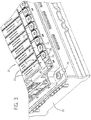
- the battery module 20 includes a number of individual prismatic electrochemical cells 30 (e.g., Li-ion electrochemical cells 30) housed in a housing 31, each electrochemical cell 30 having a positive terminal 34 and a negative terminal 36.
- the prismatic electrochemical cells 30 generally include terminal ends having the terminals 34, 36, base ends opposite the terminal ends, broad faces extending between the terminal and base ends, and narrow faces extending between the broad faces.
- a first terminal (e.g., the positive terminal 34) of a first electrochemical cell is positioned proximate a second terminal (e.g., the negative terminal 36) of a second electrochemical cell.
- the electrochemical cells 30 may be coupled together in series (e.g., positive terminal 34 to negative terminal 36, as shown) or in parallel (e.g., positive terminal 34 to positive terminal 34 or negative terminal 36 to negative terminal 36).
- the battery module 20 may include some electrochemical cells 30 coupled together in parallel and some electrochemical cells 30 coupled together in series. To couple two adjacent electrochemical cells 30 in series, an electrical path is provided between the positive terminal 34 of a first of the two adjacent electrochemical cells 30 and the negative terminal 36 of a second of the two adjacent electrochemical cells 30.
- an electrical path is provided between, for example, the positive terminal 34 of a first of the two adjacent electrochemical cells 30 and the positive terminal 34 of a second of the two adjacent electrochemical cells 30.
- two adjacent electrochemical cells 30 may also be coupled together in parallel by providing an electrical path between their respective negative terminals 36 as opposed to between their respective positive terminals 34.
- the labeled positive terminal 34 in the illustrated embodiment is also electrically coupled to an external terminal 39 (e.g., an external positive terminal) of the battery module 20, where the external terminal 39 is configured to be coupled to, for example, one or more loads.
- an external terminal 39 e.g., an external positive terminal
- connections between the electrochemical cells 30 are replicated between all the terminals 34, 36 of all the electrochemical cells 30 of the battery module 20 to form an aggregate electrical network of connections.
- a negative terminal 36 on the other side of the battery module 20 (e.g., on the other side of the aggregate electrical network) opposite to the illustrated external terminal 39 may be coupled to another external terminal 39 (e.g., a negative external terminal).
- the two external terminals 39 may be coupled to the one or more loads such that the aggregate network of connections of the electrochemical cells 30 may enable a charge to be provided from the battery module 20 to the one or more loads.
- each terminal 34, 36 on the exterior of each electrochemical cell 30 represents an electrical contact to the aggregated network of connections of the battery module 20.
- each electrochemical cell 30 includes a positive terminal 34 coupled to the negative terminal 36 of an adjacent cell 30 and a negative terminal 36 coupled to the positive terminal 34 of the other adjacent cell 30.
- the electrochemical cells 30 may be disposed in one or more rows such that the electrochemical cells 30 on either end of a row are adjacent to only one electrochemical cell 30. Accordingly, the cells 30 on either end of the row include one terminal coupled to, e.g., major terminals (not shown) of the battery module 20 configured to couple the battery module 20 to a load (e.g., of the xEV 10 or another load).
- an electrical path is provided between the terminals 34, 36 via a bus bar connection assembly 37 in accordance with the present disclosure.
- the bus bar connection assembly 37 is configured to provide the electrical path between the respective first terminal 34 (e.g., a positive terminal) of a first one of the electrochemical cells 30 and the respective second terminal 36 (e.g., a negative terminal) of a second one of the electrochemical cells 30.
- the disclosed bus bar connection assembly 37 may be used to couple (e.g., provide an electrical path between) two positive terminals or two negative terminals in a parallel connection, or a positive terminal and a negative terminal in a series connection (as shown).
- the bus bar connection assembly 37 as described in detail below, may be used to couple terminals 34, 36 having the same or two different materials.
- the bus bar connection assembly 37 includes adapters 38 configured to fit over the terminals 34, 36 of the adjacent electrochemical cells 30.
- the adapters 38 each include at least a conductive portion (e.g., a metallic portion) configured to contact the terminals 34, 36 of the electrochemical cells 30, which are also conductive (e.g., metallic), to establish an electrical path between the terminals 34, 36.
- a conductive portion e.g., a metallic portion
- each electrochemical cell 30 is electrically coupled to the adapters 38 that fit around its respective terminals 34, 36.
- a bus bar 40 (e.g., a metallic, bi-metallic, alloyed, or otherwise conductive bus bar) is disposed in recesses 42 of the two adjacent adapters 38.
- each adapter 38 in the illustrated embodiment includes a plastic or otherwise electrically insulative material (e.g., dielectric material) disposed around the metallic portion of the adapter 38.
- an "electrically insulative material” includes materials that do not substantially transmit electric current therethrough. The electrically insulative material may extend upwardly proximate the recess 42 of the adapter 38 and the conductive bus bar 40 disposed in the recess. Accordingly, the electrical path provided between the two terminals 34, 36 of the adjacent electrochemical cells 30 is protected by the electrically insulative material.
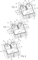
- the adapters 38 may, depending on the embodiment, be configured to enable coupling of certain electrochemical cells 30 of the battery module 20 in series, in parallel, or in a combination thereof. Indeed, presently contemplated embodiments of the adapters 38 are capable of coupling terminals having the same material, or terminals having two different materials. For example, perspective views of embodiments of the bus bar connection assembly 37 having adapters 38 configured to couple together terminals having various materials are shown in FIGS. 4-6 .
- the illustrated adapters 38 are configured to couple the first terminal 34, having a first conductive material, with the adjacent second terminal 36, having a second conductive material different than the first conductive material.
- the first terminal 34 may be aluminum and the second terminal 36 may be copper.
- an electrochemical half-reaction occurs at each of the positive and negative electrodes.
- the electrochemical half-reaction at the positive electrode may be a reaction in which one or more lithium ions are reversibly (based on an equilibrium) dissociated from the positive electrode active material, thereby also releasing one or more electrons (equal in number to the number of dissociated lithium ions).
- the electrochemical half-reaction that occurs may be a reaction in which one or more lithium ions and one or more electrons (of equal number) are reversibly associated with the negative electrode active material (e.g., carbon).
- the equilibria at the electrodes favor dissociation of the lithium ions and electrons from the negative electrode active material and re-association of the electrons and lithium ions with the positive electrode active material.
- the reverse is true.
- the movement of the ions into the electrodes is commonly referred to as intercalation or insertion, and the movement of the ions away from the electrodes is commonly referred to as deintercalation or extraction.
- the positive and negative electrodes of the present batteries will generally be capable of lithium ion intercalation and deintercalation.
- the particular materials selected for a current collector for each of the positive and negative electrodes will also depend on the particular materials used as their respective active materials.
- the current collector e.g. the first terminal 34
- the current collector may be aluminum
- the current collector e.g., the second terminal 36
- the electrical path between the two terminals 34, 36 is generally established via adapters 38.
- the adapter 38 that fits over (or around) the first terminal 34, in the illustrated embodiment, may also include aluminum,
- a conductive portion 50 (e.g., metallic portion) of the adapter 38 is aluminum (e.g., the same conductive material as the terminal 34).
- the adapter 38 that fits over (or around) the second terminal 36, in the illustrated embodiment may include a bi-material (e.g., bi-metallic) conductive portion 52.
- the conductive and bi-material conductive portions 50, 52 may include any conductive material(s), but, for simplicity, may be referred to as metallic and bi-metallic portions 50, 52 herein.
- the bi-metallic portion 52 includes a first portion 54 (e.g., having the same material as the second terminal 36, copper) that contacts the second terminal 36.
- the first portion 54 transitions to a second portion 56 (e.g., aluminum, the same material as the first terminal 34) proximate to the recess 42 of the adapter 38.
- each recess 42 (e.g., recessed portion) of the two adjacent adapters 38 includes the same material (e.g., aluminum).
- the conductive bus bar 40 also includes, for example, aluminum to correspond with aluminum in the recessed portions 42 in each of the adapters 38.
- the first portion 54 of the bi-metallic portion 52 of the adapter 38 that corresponds with the illustrated copper terminal 36 is configured to transition (e.g., from the first portion 54 to the second portion 56) to a material, in the second portion 56, that corresponds with the conductive bus bar 40.
- the electrochemical cells 30 may be coupled together in series or in parallel, as previously described.
- the electrochemical cell 30 may include two copper terminals 34, 36, two aluminum terminals 34, 36, one copper terminal 36/34 and one aluminum terminal 34/36, or two terminals 34, 36 having the same or different other materials.
- the internal chemistry determines the type of material used for each terminal 34, 36 (e.g., of the anode and cathode).
- two terminals 34, 36 having the same material may be electrically coupled to couple cells in series or in parallel, and two terminals 34, 36 having different materials may be electrically coupled to couple cells in series or in parallel.
- battery modules in accordance with the present disclosure may include multiple types of adapters and/or bus bars.
- the adapters 38 may include an electrically insulative portion 58 configured to block external, loose, or proximate materials or parts from contacting the conductive portions 50, 52 of the adapters 38, which could otherwise cause a potential short circuit.
- the electrically insulative portion 58 (e.g., having plastic) may surround, for example, outer sides of the adapter 38.
- the plastic portion 58 may also include a wall 60 that extends upwardly from the adapter 38 (e.g., in a direction parallel to the terminals 34, 36 extending upwardly from the cells 30) proximate the recess 42 of the adapter 38.
- the wall 60 may partially define the recess 42 or recessed portion configured to receive the bus bar 40 and may be disposed proximate a far side 62 of the bus bar 40 and recessed portion 42 of the adapter 38.
- the adapters 38 may include the same or similar plastic portions 58 and corresponding walls 60 to block or reduce a likelihood of a short circuit, as described above.
- the illustrated embodiments and corresponding description are not included to be limited to the combination of elements shown. Rather, the disclosed elements of the bus bar connection assembly 37 may be used in various combinations as appropriate for electrochemical cells 30 coupled in series, coupled in parallel, having terminals 34, 36 with corresponding materials, or having terminals 34, 36 with different materials.
- certain embodiments of the battery module 20 may include a bus bar connection assembly 37 configured to couple together terminals 34, 36 having the same conductive material.
- a bus bar connection assembly 37 configured to couple together terminals 34, 36 having the same conductive material.
- adjacent first and second terminals 34, 36 e.g., both extending from an anode
- copper as their conductive material
- each terminal 34, 36 has an embodiment of the adapter 38 having the bi-metallic portion 52 described above.
- the terminals 34, 36 may be copper and the bi-metallic portion 52 of each adapter 38 may include the first (e.g., copper) portion 54 proximate (e.g., contacting) the terminal 34, 36 and the second (e.g., aluminum) portion 56 proximate the recess 42 (e.g., recessed portion) of the adapter 38.
- an aluminum embodiment of the conductive bus bar 40 fits within the recesses 42 of both adapters 38 and contacts the aluminum portions 56 of both adapters 38, electrically coupling the two terminals 34, 36.
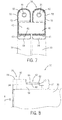
- certain embodiments of the battery module 20 may include a bus bar connection assembly 37 configured to couple two adjacent terminals together, where the adapters 38 only include a single conductive material (e.g., do not include the bi-metallic portion 52 shown in FIGS, 4 and 5 ).
- a bus bar connection assembly 37 configured to couple two adjacent terminals together, where the adapters 38 only include a single conductive material (e.g., do not include the bi-metallic portion 52 shown in FIGS, 4 and 5 ).
- FIG. 6 an embodiment of the bus bar connection assembly 37 is shown having two adapters 38 with corresponding metallic portions 50 having aluminum.
- the terminals 34, 36 e.g., both extending from a cathode
- An aluminum conductive bus bar 40 is configured to provide the electrical path between the adapters 38, where the bus bar 40 is disposed within (and spans between) the two recessed portions 42 of the adjacent adapters 38.
- the bus bar 40 is configured to be disposed within, and span between, the two recesses 42 of the adjacent adapters 38.
- a top view of an embodiment of the bus bar connection assembly 37 having the bus bar 40 spanning between two recesses 42 of adjacent adapters 38 is shown in FIG. 7 .
- the bus bar 40, and the metallic (or otherwise conductive) portions 50 of the adapters 38 e.g., the electrical path
- the bus bar 40, and the metallic (or otherwise conductive) portions 50 of the adapters 38 is at least partially protected from a short circuit via the plastic (or otherwise electrically insulative) portions 58 of the adapters 38.
- the plastic portions 58 substantially surround outer surfaces or edges 70 of the adapters 38, Additionally, the plastic portions 58 include walls 60 that extend upwardly from the adapters 38 proximate the far side or far edge 62 of the bus bar 40 (or recesses 42).
- the walls 60 are configured to provide additional protection from a short circuit, but may also be configured to guide placement and securement (e.g., via welding, adhesive) of the bus bar 40 into the recesses 42 of the adjacent adapters 38.
- the plastic portions 58 and corresponding walls 60 may not cover a top portion of the metallic portions 50 (or bi-metallic portions 52) of the adapters 38, such that the bus bar 40 may be placed into the recesses 42 and accessed from above the electrochemical cells 30 for securing the bus bar 40 (e.g., via welding, adhesive) to the adapters 38.
- the recesses 42 of the adapters 38 and the plastic portions 58 (and corresponding walls 60) surrounding the metallic/bi-metallic portions 50, 52 of the adapters 38 are configured to protect the electrical path between the two terminals 34, 36 from being contacted by other components.
- the recesses 42 also increase the energy density of the battery module 20.
- the bus bars 40 are disposed in-line (e.g., in plane) with (or below) the terminals 34, 36, instead of on top of (and above) the terminals 34, 36.
- a height of the battery module 20 may be reduced compared to battery modules having bus bars disposed on top of and above the terminals 34, 36, thereby comparatively reducing the volume and increasing the energy density of the battery module 20.
- each electrochemical cell 30 of the battery module 20 may include slightly different widths (e.g., within manufacturing tolerances).
- the electrochemical cells 30 may be positioned immediately adjacent one another before coupling the bus bar 40 to the recessed portions 42.
- space is saved between the electrochemical cells 30 and an energy density of the battery module 20 is increased.
- FIG. 8 depicts a side view of an embodiment of one electrochemical cell 30 having the adapter 38 with the bus bar 40 disposed in the recess 42 of the adapter 38.
- a top surface 80 of the bus bar 40 is disposed below a top surface 82 of the terminal 34 with respect to vertical axis 81.
- the top surface 82 of the terminal 34 in the illustrated embodiment, is flush (e.g., in-line or in-plane) with a top surface 84 of the adapter 38.
- all components of the bus bar connection assembly 37 are disposed in-line with and/or below the top surface 82 of the terminal 34 (with respect to the vertical axis 81), thereby reducing a clearance of the illustrated electrochemical cell 30 compared to other arrangements where terminals are fitted directly (and/or rigidly) with a bus bar.
- the reduced clearance reduces a height and, thus, a volume of the battery module 20, thereby increasing the energy density of the battery module 20.
- the adapters 38 may be included (e.g., disposed on or integrally formed with) on a board (e.g., a panel, an e-carrier configured to hold certain portions of the bus bar assembly 37 and/or other sensors or circuitry and to fit over the electrochemical cells 30, a printed circuit board (PCB), or some other board) configured to fit over all (or some) of the electrochemical cells 30 of the battery module 20.
- a board e.g., a panel, an e-carrier configured to hold certain portions of the bus bar assembly 37 and/or other sensors or circuitry and to fit over the electrochemical cells 30, a printed circuit board (PCB), or some other board
- PCB printed circuit board
- FIG-11 show embodiments of the bus bar assembly 37 having adapters 38 disposed on a board 90 (e.g., an e-carrier) configured to be disposed over all or some of the electrochemical cells 30 of the battery module 20 (e.g., longitudinally between tops of the electrochemical cells 30 (e.g., tops having the terminals 34, 36 extending therefrom) and the adapters 38).
- a board 90 e.g., an e-carrier
- FIG. 9 a cross-sectional side view of one electrochemical cell 30 of the battery module 20 having the corresponding adapter 38 disposed on the board 90 is shown.
- the plastic (or otherwise electrically insulative) portion 58 of the illustrated adapter 38 is integrally formed with the board 90 (which includes the plastic portions 58 of all the other adapters 38), in which the board 90 is configured to be disposed over all the electrochemical cells 30 of the battery module 20.
- the board 90 includes multiple openings 92 through which the terminals 34, 36 of the electrochemical cells 30 extend.
- the openings 92 extend through the plastic portions 58 and the metallic (or otherwise electrically conductive) portions 50 of the adapters 38 also disposed on the board 90.
- each terminal 34, 36 extends through the plastic portion 58 and an outer surface 93 of the terminal (e.g., terminal 34 in the illustrated embodiment) contacts an inner surface 94 of the metallic portion 50 of the adapter 38.
- the metallic portions 50 (or bi-metallic portions 52, depending on the embodiment) of the adapters 38 may be disposed in the plastic portions 58 integrally formed with the board 90 before or after disposing the board 90 over the electrochemical cells 30.
- the bus bar 40 may be disposed in the recesses 42 of the adapters 38 before or after disposing the board 90 over the electrochemical cells 30 and disposing the metallic portions 50 (or bi-metallic portions 52) into the plastic portions 58.
- the metallic portions 50 (or bi-metallic portions 52) of the adapters 38 may be disposed in the plastic portions 58 of the board 90 and the bus bars 40 may be disposed within (and spanning between) the recesses 42 of the adapters 38 before disposing the board 90 over the electrochemical cells 30. In doing so, assembly of the battery module 20 may be made more efficient and all the electrical paths between the terminals 34, 36 of the electrochemical cells 30 of the entire battery module 20 (or a portion thereof) may be established substantially simultaneously.
- the board 90 having the plastic portions 58 integrally formed on the board 90 may be disposed over the electrochemical cells 30 before the metallic portions 50 (or bi-metallic portions 52) of the adapters 38 are disposed within the plastic portions 58 and before the bus bars 40 are disposed in the recesses 42 of the adapters 38. In either configuration, the board 90 facilitates a more efficient assembly of the bus bar connection assembly 37 and the battery module 20 in general.
- the assembled bus bar connection assembly 37 reduces an overall clearance of the battery module 20, as a top surface 95 of the adapter 38 is in plane with (or, in other embodiments, below) the top surface 82 of the terminal 34 (or terminal 36) and a top surface 96 of the bus bar 40 is below (or, in some embodiments, in plane with) the top surface 82 of the terminal 34 (or terminal 36).
- the board 90 e.g., e-carrier
- the board 90 does not protrude beyond the terminals 34, 36, unlike other arrangements.
- the openings 92 of the adapters 38 configured to receive the terminals 34, 36 of the electrochemical cells 30 may be tapered.
- an embodiment of one electrochemical cell 30 (e.g., of the battery module 20) having the adapter 38 with a tapered opening 98 is shown in a cross-sectional side view in FIG. 10 .
- the tapered opening 98 extends through the plastic portion 58 and the metallic portion 50 (or bi-metallic portion 52, depending on the embodiment). It should be noted, however, that the tapered opening 98 may only be tapered for a portion of the opening 98 through which the terminal (e.g., parallel with the vertical axis 81) extends.
- the plastic portion 58 is tapered and the metallic portion 50 is substantially non-tapered (e.g., the inner surface 94 of the metallic portion 50 is parallel with the outer surface 93 of the terminal 34).
- the portion of the opening 98 extending through the metallic portion 50 of the adapter 38 is also tapered.
- the terminal 34 may more readily contact the inner surface 94 of the metallic portion 50.
- the terminal 34 may also be tapered,
- the board 90 may not include any portions of the adapters 38 integrally formed on the board 90.
- the adapters 38 may be pre-assembled or partially pre-assembled (e.g., separately) and coupled to the board 90 (which may have a substantially flat top surface 100) via welding, adhesive, fasteners, clamps, clips, press fitting, or some other coupling mechanism after pre-assembly.
- pre-assembled or partially pre-assembled adapters 38 are attached to the board 90 via adhesive, fasteners, welding, clamps, clips, press fitting, or any other appropriate coupling technique.
- the adapters 38 may be separately assembled (e.g., with the metallic or bi-metallic portions 50, 52 disposed in the plastic portions 58) and placed onto the board 90 before or after the board 90 is placed over the terminals 34, 36 of the electrochemical cells 30.
- the board 90 and the adapters 38 have the openings 92 configured to be aligned during assembly to receive the terminals 34, 36 of the electrochemical cells 30.
- the bus bars 40 may be disposed into the recesses 42 of the adapters 38 before or after disposing the adapters 38 on the board 90 and/or before or after disposing the board 90 over the terminals 34, 36.
- the electrochemical cells 30 are coupled together at the terminals 34, 36 and one terminal 34, 36 on either end of the arranged row or stack of cells 30 may be coupled to external terminals 39 of the battery module 20, where the external terminals 39 may be coupled to one or more loads.
- the bus bar connection assembly 37 having the board 90 may be manufactured and assembled in a number of different ways.
- the adapters 38 may be entirely pre-assembled before disposing the adapters 38 on the board 90.
- the metallic portions 50 (and/or bi-metallic portions 52) may be disposed into the plastic portions 58 of the adapters and the bus bars 40 may be disposed into the recesses 42 of the adapters 38 to assemble the adapters 38.
- the bus bars 40 may be welded or otherwise coupled to the metallic portions 50 (or bi-metallic portions 52) of the two adjacent adapters 38, as previously described, during or after pre-assembly of the adapters 38.
- FIG. 12 A process flow diagram of a method 110 of establishing an electrical connection or path between terminals 34, 36 of two electrochemical cells 30 is shown in FIG. 12 .
- the method 110 includes disposing a first adapter 38 over a first terminal 34 of a first electrochemical cell 30, where a first electrically conductive (e.g., metallic) portion 50 of the first adapter 38 contacts the first terminal 34 (block 112).
- the method 110 also includes disposing a second adapter 38 over a second terminal 36 of a second electrochemical cell 30, where a second electrically conductive (e.g., metallic) portion 50 of the second adapter 38 contacts the second terminal 36 (block 114).
- the method 110 includes disposing a bus bar 40 in a first recess 42 of the first metallic portion 50 of the first adapter 38 and a second recess 40 of the second metallic portion 50 of the second adapter 38, thereby establishing an electrical path from the first terminal 34, to the first metallic portion 50, to the bus bar 40, to the second metallic portion 50, and to the second terminal 36 (block 116).
- the element numbers and resulting structure of the above described method 100 generally corresponds with the embodiment of the bus bar connection assembly 37 illustrated in FIG. 6 . Similar methods apply to any of the structural embodiments previously discussed with reference to the figures.
- embodiments of the present disclosure include a battery module with a bus bar connection assembly configured to couple terminals of adjacent electrochemical cells in a way that reduces a volume of the battery module, thereby enhancing the energy density of the battery module.
- the bus bar connection assembly includes adapters configured to fit over or terminals of adjacent electrochemical cells, where the adapters include recessed portions configured to be aligned together to receive a bus bar. The bus bar spans between the recessed portion of the adjacent adapters of the adjacent electrochemical cells, contacting the metallic portions of both adapters.
- an electrical path is established between the adjacent terminals, while top surfaces of the terminals are disposed above any other surface of components of the bus bar connection assembly (e.g., the adapters and the bus bars). Further, by disposing the bus bar in the adjacent recesses, and by providing a plastic portion on each of the adapters around the metallic portions and proximate the recesses, the electrical path is protected from potential short circuits occurring due to components contacting the electrical path. Also, the adapters can be used to mitigate differences in dimensions, sizes, etc., as previously discussed, and also provides a more robust connection.
- the technical effects and technical problems in the specification are exemplary and are not limiting. It should be noted that the embodiments described in the specification may have other technical effects and can solve other technical problems.
Landscapes
- Chemical & Material Sciences (AREA)
- Chemical Kinetics & Catalysis (AREA)
- Electrochemistry (AREA)
- General Chemical & Material Sciences (AREA)
- Engineering & Computer Science (AREA)
- Materials Engineering (AREA)
- Manufacturing & Machinery (AREA)
- Connection Of Batteries Or Terminals (AREA)
- Battery Mounting, Suspending (AREA)
Claims (14)
- Module de batterie (20), comprenant :- une première cellule électrochimique (30) ayant une première borne (34, 36) ;- une deuxième cellule électrochimique (30) ayant une deuxième borne (34, 36) ; et- une connexion de barre omnibus (37) connectant électriquement les première et deuxième cellules électrochimiques (30), comprenant :la barre omnibus (40) étant disposée à l'intérieur des premier et deuxième évidements (42) de telle sorte qu'une surface supérieure (80, 96) de la barre omnibus (40) ne soit pas disposée plus haut que les surfaces supérieures (82) des première et deuxième bornes (34, 36) par rapport à un axe vertical (81) s'étendant parallèlement aux première et deuxième bornes (34, 36),- un premier adaptateur (38) recouvrant au moins une partie de la première borne (34, 36) de la première cellule électrochimique (30), le premier adaptateur (38) comprenant un premier évidement (42) positionné à proximité de la première borne (34, 36) ;- un deuxième adaptateur (38) recouvrant au moins une partie de la deuxième borne (34, 36) de la deuxième cellule électrochimique (30), le deuxième adaptateur (38) comprenant un deuxième évidement (42) positionné à proximité du premier évidement (42) et au moins partiellement aligné avec celui-ci ; et- une barre omnibus (40) qui s'étend entre le premier évidement (42) du premier adaptateur (38) et le deuxième évidement (42) du deuxième adaptateur (38) pour établir un trajet électrique,
une première surface supérieure (84, 95) du premier adaptateur (38) étant au même niveau que la surface supérieure (82) de la première borne (34, 36) immédiatement adjacente à la première borne (34, 36), et une deuxième surface supérieure (84, 95) du deuxième adaptateur (38) étant au même niveau que la surface supérieure (82) de la deuxième borne (34, 36) immédiatement adjacente à la deuxième borne (34, 36). - Module de batterie (20) selon la revendication 1,
le premier adaptateur (38) comprenant une première partie conductrice (50, 52) en contact avec la première borne (34, 36), le deuxième adaptateur (38) comprenant une deuxième partie conductrice (50, 52) en contact avec la deuxième borne (34, 36), et la barre omnibus (40) étant en contact électrique avec la première partie conductrice (50, 52) et la deuxième partie conductrice (50, 52) pour établir le trajet électrique. - Module de batterie (20) selon la revendication 2,
le premier adaptateur (38) comprenant une première partie électriquement isolante (58) entourant au moins partiellement la première partie conductrice (50, 52), le deuxième adaptateur (38) comprenant une deuxième partie électriquement isolante (58) entourant au moins partiellement la deuxième partie conductrice (50, 52). - Module de batterie (20) selon la revendication 3,
la première partie électriquement isolante (58) comprenant une première paroi (60) et la deuxième partie électriquement isolante (58) comprenant une deuxième paroi (60), les première et deuxième parois (60) étant disposées sur un côté éloigné (62) des premier et deuxième évidements (42) au moins partiellement alignés opposés à un côté proche des premier et deuxième évidements (42) au moins partiellement alignés, et les côtés proches respectifs des premier et deuxième évidements (42) au moins partiellement alignés étant disposés plus près des première et deuxième bornes (34, 36) que les côtés éloignés respectifs (62) des premier et deuxième évidements (42) au moins partiellement alignés. - Module de batterie (20) selon l'une des revendications 2 à 4,
la première partie conductrice (52) étant une partie conductrice à deux matériaux (52) comprenant un premier matériau conducteur et un deuxième matériau conducteur différent du premier matériau conducteur, l'un des premier et deuxième matériaux conducteurs étant configuré pour entrer en contact avec la première borne (34, 36) et l'autre des premier et deuxième matériaux conducteurs étant configuré pour entrer en contact avec la barre omnibus (40). - Module de batterie (20) selon la revendication 5,
le premier matériau conducteur étant le cuivre et le deuxième matériau conducteur étant l'aluminium. - Module de batterie (20) selon la revendication 5,
le premier matériau conducteur étant l'aluminium et le deuxième matériau conducteur étant le cuivre. - Module de batterie (20) selon l'une des revendications 1 à 7,
les première et deuxième cellules électrochimiques (30) étant des cellules électrochimiques au lithium-ion (30). - Module de batterie (20) selon l'une des revendications 1 à 8,
la connexion de barre omnibus (37) comprenant un panneau (90) disposé longitudinalement entre les première et deuxième cellules électrochimiques (30) et les premier et deuxième adaptateurs (38), le panneau (90) comprenant des ouvertures (92), et les première et deuxième bornes (34, 36) des première et deuxième cellules électrochimiques (30), respectivement, étant disposées à travers les ouvertures (92). - Module de batterie (20) selon la revendication 9,
une première partie électriquement isolante (58) du premier adaptateur (38) et une deuxième partie électriquement isolante (58) du deuxième adaptateur (38) étant formées intégralement avec le panneau (90), et une première partie conductrice (50, 52) et une deuxième partie conductrice (50, 52) des premier et deuxième adaptateurs (38), respectivement, étant disposées à l'intérieur des première et deuxième parties électriquement isolantes (58), respectivement, de telle sorte que la barre omnibus (40) disposée à l'intérieur des premier et deuxième évidements (42) soit en contact avec les première et deuxième parties conductrices (50, 52) établissant ainsi le trajet électrique entre les première et deuxième bornes (34, 36) . - Module de batterie (20) selon l'une des revendications 1 à 10,
les première et deuxième cellules électrochimiques (30) étant des cellules électrochimiques prismatiques (30). - Module de batterie (20) selon l'une des revendications 1 à 11,
les première et deuxième cellules électrochimiques (30) étant empilées l'une à côté de l'autre, la première borne (36) de la première cellule électrochimique (30) étant couplée à une anode de la première cellule électrochimique (30), et la deuxième borne (34) de la deuxième cellule électrochimique (30) étant couplée à une cathode de la deuxième cellule électrochimique (30). - Module de batterie (20) selon la revendication 11,
le module de batterie (20) comprenant des paires de première et deuxième cellules électrochimiques (30) couplées ensemble dans un réseau agrégé du module de batterie (20), et le réseau agrégé culminant en une borne positive (39) sur un premier côté du module de batterie (20) et une borne négative (39) sur un deuxième côté du module de batterie (20). - Module de batterie (20) selon l'une des revendications 1 à 13,
le premier adaptateur (38) comprenant une première ouverture (92) qui reçoit la partie de la première borne (34, 36), le deuxième adaptateur (38) comprenant une deuxième ouverture (92) qui reçoit la partie de la deuxième borne (34, 36) .
Applications Claiming Priority (2)
| Application Number | Priority Date | Filing Date | Title |
|---|---|---|---|
| US14/502,485 US9887409B2 (en) | 2014-09-30 | 2014-09-30 | Battery module bus bar connection assembly |
| PCT/US2015/036988 WO2016053418A1 (fr) | 2014-09-30 | 2015-06-22 | Ensemble de connexion de barre omnibus de module de batterie |
Publications (2)
| Publication Number | Publication Date |
|---|---|
| EP3201975A1 EP3201975A1 (fr) | 2017-08-09 |
| EP3201975B1 true EP3201975B1 (fr) | 2019-11-20 |
Family
ID=53719934
Family Applications (1)
| Application Number | Title | Priority Date | Filing Date |
|---|---|---|---|
| EP15741658.7A Active EP3201975B1 (fr) | 2014-09-30 | 2015-06-22 | Ensemble de connexion de barre omnibus de module de batterie |
Country Status (4)
| Country | Link |
|---|---|
| US (1) | US9887409B2 (fr) |
| EP (1) | EP3201975B1 (fr) |
| CN (1) | CN107210415B (fr) |
| WO (1) | WO2016053418A1 (fr) |
Families Citing this family (5)
| Publication number | Priority date | Publication date | Assignee | Title |
|---|---|---|---|---|
| EP3750201A4 (fr) * | 2018-02-09 | 2021-09-08 | Ravenswood Solutions Inc. | Adaptateur de batterie |
| DE102018206231B3 (de) | 2018-04-23 | 2019-09-19 | Triathlon Batterien Gmbh | Vorrichtung zum elektrischen Kontaktieren einer Leiterplatte an ein Batteriezellenverbundsystem und Einrichtung mit einer derartigen Vorrichtung und einem derartigen Batteriezellenverbundsystem |
| US10964988B2 (en) | 2018-10-08 | 2021-03-30 | Ford Global Technologies, Llc | Fusible bimetallic bus bars for battery arrays |
| CN211017199U (zh) * | 2019-12-31 | 2020-07-14 | 宁德时代新能源科技股份有限公司 | 电池模块、电池组及装置 |
| EP4011668A1 (fr) * | 2020-12-09 | 2022-06-15 | Volvo Car Corporation | Procédé d'assemblage d'un système de batterie à un châssis d'un véhicule électrique |
Citations (3)
| Publication number | Priority date | Publication date | Assignee | Title |
|---|---|---|---|---|
| US20060091855A1 (en) * | 2004-10-28 | 2006-05-04 | Samsung Sdi Co., Ltd. | Rechargeable battery module |
| US20100216009A1 (en) * | 2009-02-25 | 2010-08-26 | Yong-Sam Kim | Battery module |
| JP2010225449A (ja) * | 2009-03-24 | 2010-10-07 | Autonetworks Technologies Ltd | 接続ユニット |
Family Cites Families (25)
| Publication number | Priority date | Publication date | Assignee | Title |
|---|---|---|---|---|
| US5143804A (en) | 1991-05-08 | 1992-09-01 | Duracell Inc. | Battery assembly |
| JPH10106539A (ja) * | 1996-09-26 | 1998-04-24 | Matsushita Electric Ind Co Ltd | 組蓄電池の液絡防止構造 |
| US6399238B1 (en) | 1999-12-13 | 2002-06-04 | Alcatel | Module configuration |
| KR100684743B1 (ko) * | 2004-10-28 | 2007-02-20 | 삼성에스디아이 주식회사 | 이차 전지 모듈 |
| US7074095B2 (en) * | 2004-11-02 | 2006-07-11 | Te-Yu Perng | Car battery post fixing structure |
| US7489105B2 (en) | 2005-03-21 | 2009-02-10 | Eveready Battery Company, Inc. | Portable power supply |
| EP2022111A2 (fr) | 2006-04-28 | 2009-02-11 | Johnson Controls Technology Company | Ensemble module de batterie |
| CN101652880B (zh) | 2007-02-09 | 2012-05-30 | 江森自控帅福得先进能源动力系统有限责任公司 | 用于电池的汇流排 |
| US8313855B2 (en) | 2007-08-02 | 2012-11-20 | Johnson Controls—SAFT Advanced Power Solutions LLC | Interconnection washer assembly for a battery assembly |
| US20090075163A1 (en) | 2007-09-14 | 2009-03-19 | Ford Global Technologies, Llc | System and method for electrically connecting terminals of a battery |
| CN102084517A (zh) | 2008-05-15 | 2011-06-01 | 江森自控帅福得先进能源动力系统有限责任公司 | 电池系统 |
| JP4539763B2 (ja) * | 2008-06-13 | 2010-09-08 | トヨタ自動車株式会社 | 電極 |
| JP2010061961A (ja) | 2008-09-03 | 2010-03-18 | Tokai Rika Co Ltd | 二次電池の端子構造、二次電池及び二次電池モジュール |
| US7798833B2 (en) | 2009-01-13 | 2010-09-21 | Gm Global Technology Operations, Inc. | Low inductance busbar assembly |
| US8263255B2 (en) * | 2009-10-01 | 2012-09-11 | Sb Limotive Co., Ltd. | Rechargeable battery and battery module |
| US8580423B2 (en) | 2009-10-22 | 2013-11-12 | Samsung Sdi Co., Ltd. | Bus bar holder and battery pack including the same |
| KR101146677B1 (ko) | 2009-10-30 | 2012-05-22 | 에스비리모티브 주식회사 | 버스바홀더 |
| KR20110055255A (ko) * | 2009-11-19 | 2011-05-25 | 에스비리모티브 주식회사 | 버스 바와 이를 구비한 전지 모듈 |
| JP2012084318A (ja) | 2010-10-08 | 2012-04-26 | Auto Network Gijutsu Kenkyusho:Kk | バスバーモジュール |
| KR101223520B1 (ko) * | 2010-11-10 | 2013-01-17 | 로베르트 보쉬 게엠베하 | 전지 모듈 |
| KR101222371B1 (ko) | 2010-11-12 | 2013-01-16 | 로베르트 보쉬 게엠베하 | 이차 전지의 단자, 이차 전지의 단자 조립 방법, 이차 전지 모듈 및 그 조립 방법 |
| US9537121B2 (en) * | 2011-03-18 | 2017-01-03 | Samsung Sdi Co., Ltd. | Secondary battery and secondary battery pack having a flexible collecting tab extending through a cap plate |
| KR101244739B1 (ko) | 2011-05-09 | 2013-03-18 | 로베르트 보쉬 게엠베하 | 전지 모듈 |
| US8684758B2 (en) | 2011-10-03 | 2014-04-01 | Mersen Usa Newburyport-Ma, Llc | Terminal unit having fused combiner/distribution bus bar assembly |
| KR20140060633A (ko) | 2012-11-12 | 2014-05-21 | 주식회사 엘지화학 | 버스 바 어셈블리를 포함하는 전지모듈 및 이를 포함하는 전지팩 |
-
2014
- 2014-09-30 US US14/502,485 patent/US9887409B2/en active Active
-
2015
- 2015-06-22 EP EP15741658.7A patent/EP3201975B1/fr active Active
- 2015-06-22 WO PCT/US2015/036988 patent/WO2016053418A1/fr active Application Filing
- 2015-06-22 CN CN201580056854.4A patent/CN107210415B/zh active Active
Patent Citations (3)
| Publication number | Priority date | Publication date | Assignee | Title |
|---|---|---|---|---|
| US20060091855A1 (en) * | 2004-10-28 | 2006-05-04 | Samsung Sdi Co., Ltd. | Rechargeable battery module |
| US20100216009A1 (en) * | 2009-02-25 | 2010-08-26 | Yong-Sam Kim | Battery module |
| JP2010225449A (ja) * | 2009-03-24 | 2010-10-07 | Autonetworks Technologies Ltd | 接続ユニット |
Also Published As
| Publication number | Publication date |
|---|---|
| US20160093863A1 (en) | 2016-03-31 |
| US9887409B2 (en) | 2018-02-06 |
| WO2016053418A1 (fr) | 2016-04-07 |
| EP3201975A1 (fr) | 2017-08-09 |
| CN107210415B (zh) | 2020-06-16 |
| CN107210415A (zh) | 2017-09-26 |
Similar Documents
| Publication | Publication Date | Title |
|---|---|---|
| US20220320650A1 (en) | Thermal epoxy and positioning of electrochemical cells | |
| US10665848B2 (en) | Battery module bus bar carrier having guide extensions system and method | |
| US10629884B2 (en) | Flexible ribs of a bus bar carrier | |
| US9705121B2 (en) | Lead frame for a battery module | |
| US20210320356A1 (en) | Fixation of electrochemical cells in a housing of a battery module | |
| EP3201975B1 (fr) | Ensemble de connexion de barre omnibus de module de batterie | |
| US11495834B2 (en) | Turnable carrier for electrical components of a battery module | |
| US10673050B2 (en) | Battery module terminal system and method | |
| US10164296B2 (en) | Battery module separator plates | |
| US10177364B2 (en) | System and method of overmolded terminal posts of a battery module | |
| US20160336578A1 (en) | Features for preventing short circuit in a battery module | |
| WO2019010323A1 (fr) | Collecteur de courant monopièce pour cellule de batterie | |
| US20220271394A1 (en) | Battery module and bus bar having stress-relieving features |
Legal Events
| Date | Code | Title | Description |
|---|---|---|---|
| STAA | Information on the status of an ep patent application or granted ep patent |
Free format text: STATUS: THE INTERNATIONAL PUBLICATION HAS BEEN MADE |
|
| PUAI | Public reference made under article 153(3) epc to a published international application that has entered the european phase |
Free format text: ORIGINAL CODE: 0009012 |
|
| STAA | Information on the status of an ep patent application or granted ep patent |
Free format text: STATUS: REQUEST FOR EXAMINATION WAS MADE |
|
| 17P | Request for examination filed |
Effective date: 20170324 |
|
| AK | Designated contracting states |
Kind code of ref document: A1 Designated state(s): AL AT BE BG CH CY CZ DE DK EE ES FI FR GB GR HR HU IE IS IT LI LT LU LV MC MK MT NL NO PL PT RO RS SE SI SK SM TR |
|
| AX | Request for extension of the european patent |
Extension state: BA ME |
|
| RAP1 | Party data changed (applicant data changed or rights of an application transferred) |
Owner name: JOHNSON CONTROLS TECHNOLOGY COMPANY |
|
| RIN1 | Information on inventor provided before grant (corrected) |
Inventor name: DEKEUSTER, RICHARD M. Inventor name: MACK, ROBERT J. |
|
| DAV | Request for validation of the european patent (deleted) | ||
| DAX | Request for extension of the european patent (deleted) | ||
| STAA | Information on the status of an ep patent application or granted ep patent |
Free format text: STATUS: EXAMINATION IS IN PROGRESS |
|
| 17Q | First examination report despatched |
Effective date: 20180221 |
|
| GRAP | Despatch of communication of intention to grant a patent |
Free format text: ORIGINAL CODE: EPIDOSNIGR1 |
|
| STAA | Information on the status of an ep patent application or granted ep patent |
Free format text: STATUS: GRANT OF PATENT IS INTENDED |
|
| INTG | Intention to grant announced |
Effective date: 20190604 |
|
| RAP1 | Party data changed (applicant data changed or rights of an application transferred) |
Owner name: CPS TECHNOLOGY HOLDINGS LLC |
|
| GRAA | (expected) grant |
Free format text: ORIGINAL CODE: 0009210 |
|
| STAA | Information on the status of an ep patent application or granted ep patent |
Free format text: STATUS: THE PATENT HAS BEEN GRANTED |
|
| GRAS | Grant fee paid |
Free format text: ORIGINAL CODE: EPIDOSNIGR3 |
|
| AK | Designated contracting states |
Kind code of ref document: B1 Designated state(s): AL AT BE BG CH CY CZ DE DK EE ES FI FR GB GR HR HU IE IS IT LI LT LU LV MC MK MT NL NO PL PT RO RS SE SI SK SM TR |
|
| REG | Reference to a national code |
Ref country code: GB Ref legal event code: FG4D |
|
| REG | Reference to a national code |
Ref country code: CH Ref legal event code: EP |
|
| REG | Reference to a national code |
Ref country code: DE Ref legal event code: R096 Ref document number: 602015042051 Country of ref document: DE |
|
| REG | Reference to a national code |
Ref country code: IE Ref legal event code: FG4D |
|
| REG | Reference to a national code |
Ref country code: AT Ref legal event code: REF Ref document number: 1205197 Country of ref document: AT Kind code of ref document: T Effective date: 20191215 |
|
| REG | Reference to a national code |
Ref country code: NL Ref legal event code: MP Effective date: 20191120 |
|
| REG | Reference to a national code |
Ref country code: LT Ref legal event code: MG4D |
|
| PG25 | Lapsed in a contracting state [announced via postgrant information from national office to epo] |
Ref country code: GR Free format text: LAPSE BECAUSE OF FAILURE TO SUBMIT A TRANSLATION OF THE DESCRIPTION OR TO PAY THE FEE WITHIN THE PRESCRIBED TIME-LIMIT Effective date: 20200221 Ref country code: NO Free format text: LAPSE BECAUSE OF FAILURE TO SUBMIT A TRANSLATION OF THE DESCRIPTION OR TO PAY THE FEE WITHIN THE PRESCRIBED TIME-LIMIT Effective date: 20200220 Ref country code: BG Free format text: LAPSE BECAUSE OF FAILURE TO SUBMIT A TRANSLATION OF THE DESCRIPTION OR TO PAY THE FEE WITHIN THE PRESCRIBED TIME-LIMIT Effective date: 20200220 Ref country code: SE Free format text: LAPSE BECAUSE OF FAILURE TO SUBMIT A TRANSLATION OF THE DESCRIPTION OR TO PAY THE FEE WITHIN THE PRESCRIBED TIME-LIMIT Effective date: 20191120 Ref country code: FI Free format text: LAPSE BECAUSE OF FAILURE TO SUBMIT A TRANSLATION OF THE DESCRIPTION OR TO PAY THE FEE WITHIN THE PRESCRIBED TIME-LIMIT Effective date: 20191120 Ref country code: LV Free format text: LAPSE BECAUSE OF FAILURE TO SUBMIT A TRANSLATION OF THE DESCRIPTION OR TO PAY THE FEE WITHIN THE PRESCRIBED TIME-LIMIT Effective date: 20191120 Ref country code: NL Free format text: LAPSE BECAUSE OF FAILURE TO SUBMIT A TRANSLATION OF THE DESCRIPTION OR TO PAY THE FEE WITHIN THE PRESCRIBED TIME-LIMIT Effective date: 20191120 Ref country code: LT Free format text: LAPSE BECAUSE OF FAILURE TO SUBMIT A TRANSLATION OF THE DESCRIPTION OR TO PAY THE FEE WITHIN THE PRESCRIBED TIME-LIMIT Effective date: 20191120 |
|
| PG25 | Lapsed in a contracting state [announced via postgrant information from national office to epo] |
Ref country code: IS Free format text: LAPSE BECAUSE OF FAILURE TO SUBMIT A TRANSLATION OF THE DESCRIPTION OR TO PAY THE FEE WITHIN THE PRESCRIBED TIME-LIMIT Effective date: 20200320 Ref country code: HR Free format text: LAPSE BECAUSE OF FAILURE TO SUBMIT A TRANSLATION OF THE DESCRIPTION OR TO PAY THE FEE WITHIN THE PRESCRIBED TIME-LIMIT Effective date: 20191120 Ref country code: RS Free format text: LAPSE BECAUSE OF FAILURE TO SUBMIT A TRANSLATION OF THE DESCRIPTION OR TO PAY THE FEE WITHIN THE PRESCRIBED TIME-LIMIT Effective date: 20191120 |
|
| PG25 | Lapsed in a contracting state [announced via postgrant information from national office to epo] |
Ref country code: AL Free format text: LAPSE BECAUSE OF FAILURE TO SUBMIT A TRANSLATION OF THE DESCRIPTION OR TO PAY THE FEE WITHIN THE PRESCRIBED TIME-LIMIT Effective date: 20191120 |
|
| PG25 | Lapsed in a contracting state [announced via postgrant information from national office to epo] |
Ref country code: ES Free format text: LAPSE BECAUSE OF FAILURE TO SUBMIT A TRANSLATION OF THE DESCRIPTION OR TO PAY THE FEE WITHIN THE PRESCRIBED TIME-LIMIT Effective date: 20191120 Ref country code: CZ Free format text: LAPSE BECAUSE OF FAILURE TO SUBMIT A TRANSLATION OF THE DESCRIPTION OR TO PAY THE FEE WITHIN THE PRESCRIBED TIME-LIMIT Effective date: 20191120 Ref country code: RO Free format text: LAPSE BECAUSE OF FAILURE TO SUBMIT A TRANSLATION OF THE DESCRIPTION OR TO PAY THE FEE WITHIN THE PRESCRIBED TIME-LIMIT Effective date: 20191120 Ref country code: PT Free format text: LAPSE BECAUSE OF FAILURE TO SUBMIT A TRANSLATION OF THE DESCRIPTION OR TO PAY THE FEE WITHIN THE PRESCRIBED TIME-LIMIT Effective date: 20200412 Ref country code: EE Free format text: LAPSE BECAUSE OF FAILURE TO SUBMIT A TRANSLATION OF THE DESCRIPTION OR TO PAY THE FEE WITHIN THE PRESCRIBED TIME-LIMIT Effective date: 20191120 Ref country code: DK Free format text: LAPSE BECAUSE OF FAILURE TO SUBMIT A TRANSLATION OF THE DESCRIPTION OR TO PAY THE FEE WITHIN THE PRESCRIBED TIME-LIMIT Effective date: 20191120 |
|
| REG | Reference to a national code |
Ref country code: AT Ref legal event code: MK05 Ref document number: 1205197 Country of ref document: AT Kind code of ref document: T Effective date: 20191120 |
|
| REG | Reference to a national code |
Ref country code: DE Ref legal event code: R097 Ref document number: 602015042051 Country of ref document: DE |
|
| PG25 | Lapsed in a contracting state [announced via postgrant information from national office to epo] |
Ref country code: SM Free format text: LAPSE BECAUSE OF FAILURE TO SUBMIT A TRANSLATION OF THE DESCRIPTION OR TO PAY THE FEE WITHIN THE PRESCRIBED TIME-LIMIT Effective date: 20191120 Ref country code: SK Free format text: LAPSE BECAUSE OF FAILURE TO SUBMIT A TRANSLATION OF THE DESCRIPTION OR TO PAY THE FEE WITHIN THE PRESCRIBED TIME-LIMIT Effective date: 20191120 |
|
| PLBE | No opposition filed within time limit |
Free format text: ORIGINAL CODE: 0009261 |
|
| STAA | Information on the status of an ep patent application or granted ep patent |
Free format text: STATUS: NO OPPOSITION FILED WITHIN TIME LIMIT |
|
| 26N | No opposition filed |
Effective date: 20200821 |
|
| REG | Reference to a national code |
Ref country code: DE Ref legal event code: R079 Ref document number: 602015042051 Country of ref document: DE Free format text: PREVIOUS MAIN CLASS: H01M0002200000 Ipc: H01M0050500000 |
|
| PG25 | Lapsed in a contracting state [announced via postgrant information from national office to epo] |
Ref country code: AT Free format text: LAPSE BECAUSE OF FAILURE TO SUBMIT A TRANSLATION OF THE DESCRIPTION OR TO PAY THE FEE WITHIN THE PRESCRIBED TIME-LIMIT Effective date: 20191120 Ref country code: PL Free format text: LAPSE BECAUSE OF FAILURE TO SUBMIT A TRANSLATION OF THE DESCRIPTION OR TO PAY THE FEE WITHIN THE PRESCRIBED TIME-LIMIT Effective date: 20191120 Ref country code: SI Free format text: LAPSE BECAUSE OF FAILURE TO SUBMIT A TRANSLATION OF THE DESCRIPTION OR TO PAY THE FEE WITHIN THE PRESCRIBED TIME-LIMIT Effective date: 20191120 |
|
| PG25 | Lapsed in a contracting state [announced via postgrant information from national office to epo] |
Ref country code: IT Free format text: LAPSE BECAUSE OF FAILURE TO SUBMIT A TRANSLATION OF THE DESCRIPTION OR TO PAY THE FEE WITHIN THE PRESCRIBED TIME-LIMIT Effective date: 20191120 Ref country code: MC Free format text: LAPSE BECAUSE OF FAILURE TO SUBMIT A TRANSLATION OF THE DESCRIPTION OR TO PAY THE FEE WITHIN THE PRESCRIBED TIME-LIMIT Effective date: 20191120 |
|
| REG | Reference to a national code |
Ref country code: CH Ref legal event code: PL |
|
| PG25 | Lapsed in a contracting state [announced via postgrant information from national office to epo] |
Ref country code: LU Free format text: LAPSE BECAUSE OF NON-PAYMENT OF DUE FEES Effective date: 20200622 |
|
| REG | Reference to a national code |
Ref country code: BE Ref legal event code: MM Effective date: 20200630 |
|
| PG25 | Lapsed in a contracting state [announced via postgrant information from national office to epo] |
Ref country code: CH Free format text: LAPSE BECAUSE OF NON-PAYMENT OF DUE FEES Effective date: 20200630 Ref country code: IE Free format text: LAPSE BECAUSE OF NON-PAYMENT OF DUE FEES Effective date: 20200622 Ref country code: LI Free format text: LAPSE BECAUSE OF NON-PAYMENT OF DUE FEES Effective date: 20200630 |
|
| PG25 | Lapsed in a contracting state [announced via postgrant information from national office to epo] |
Ref country code: BE Free format text: LAPSE BECAUSE OF NON-PAYMENT OF DUE FEES Effective date: 20200630 |
|
| PG25 | Lapsed in a contracting state [announced via postgrant information from national office to epo] |
Ref country code: TR Free format text: LAPSE BECAUSE OF FAILURE TO SUBMIT A TRANSLATION OF THE DESCRIPTION OR TO PAY THE FEE WITHIN THE PRESCRIBED TIME-LIMIT Effective date: 20191120 Ref country code: MT Free format text: LAPSE BECAUSE OF FAILURE TO SUBMIT A TRANSLATION OF THE DESCRIPTION OR TO PAY THE FEE WITHIN THE PRESCRIBED TIME-LIMIT Effective date: 20191120 Ref country code: CY Free format text: LAPSE BECAUSE OF FAILURE TO SUBMIT A TRANSLATION OF THE DESCRIPTION OR TO PAY THE FEE WITHIN THE PRESCRIBED TIME-LIMIT Effective date: 20191120 |
|
| PG25 | Lapsed in a contracting state [announced via postgrant information from national office to epo] |
Ref country code: MK Free format text: LAPSE BECAUSE OF FAILURE TO SUBMIT A TRANSLATION OF THE DESCRIPTION OR TO PAY THE FEE WITHIN THE PRESCRIBED TIME-LIMIT Effective date: 20191120 |
|
| PGFP | Annual fee paid to national office [announced via postgrant information from national office to epo] |
Ref country code: FR Payment date: 20230626 Year of fee payment: 9 Ref country code: DE Payment date: 20230626 Year of fee payment: 9 |
|
| PGFP | Annual fee paid to national office [announced via postgrant information from national office to epo] |
Ref country code: GB Payment date: 20230627 Year of fee payment: 9 |