EP3201894B1 - Vorrichtung zum senden und empfangen eines sensorsignals - Google Patents
Vorrichtung zum senden und empfangen eines sensorsignals Download PDFInfo
- Publication number
- EP3201894B1 EP3201894B1 EP15770840.5A EP15770840A EP3201894B1 EP 3201894 B1 EP3201894 B1 EP 3201894B1 EP 15770840 A EP15770840 A EP 15770840A EP 3201894 B1 EP3201894 B1 EP 3201894B1
- Authority
- EP
- European Patent Office
- Prior art keywords
- signal
- sensor
- sensor signal
- designed
- comparison
- Prior art date
- Legal status (The legal status is an assumption and is not a legal conclusion. Google has not performed a legal analysis and makes no representation as to the accuracy of the status listed.)
- Active
Links
- 238000012545 processing Methods 0.000 claims description 57
- 238000004422 calculation algorithm Methods 0.000 claims description 42
- 230000005540 biological transmission Effects 0.000 claims description 35
- 230000008859 change Effects 0.000 claims description 29
- 238000000034 method Methods 0.000 claims description 29
- 238000001514 detection method Methods 0.000 claims description 12
- 238000011156 evaluation Methods 0.000 claims description 12
- 230000008569 process Effects 0.000 claims description 11
- 238000012544 monitoring process Methods 0.000 claims description 9
- 238000005070 sampling Methods 0.000 claims description 7
- 238000012937 correction Methods 0.000 claims description 4
- 230000000694 effects Effects 0.000 claims description 4
- 238000012935 Averaging Methods 0.000 claims description 3
- 230000004044 response Effects 0.000 claims description 2
- 230000006870 function Effects 0.000 description 13
- 238000004364 calculation method Methods 0.000 description 12
- 230000000737 periodic effect Effects 0.000 description 8
- 238000012360 testing method Methods 0.000 description 8
- 230000008901 benefit Effects 0.000 description 3
- 238000012806 monitoring device Methods 0.000 description 3
- 238000012795 verification Methods 0.000 description 3
- 238000004458 analytical method Methods 0.000 description 1
- 238000013459 approach Methods 0.000 description 1
- 230000006399 behavior Effects 0.000 description 1
- 238000006243 chemical reaction Methods 0.000 description 1
- 238000004590 computer program Methods 0.000 description 1
- 230000002950 deficient Effects 0.000 description 1
- 230000003111 delayed effect Effects 0.000 description 1
- 230000001419 dependent effect Effects 0.000 description 1
- 238000013461 design Methods 0.000 description 1
- 238000011161 development Methods 0.000 description 1
- 230000018109 developmental process Effects 0.000 description 1
- 230000009977 dual effect Effects 0.000 description 1
- 238000009429 electrical wiring Methods 0.000 description 1
- 230000007257 malfunction Effects 0.000 description 1
- 238000004519 manufacturing process Methods 0.000 description 1
- 238000013507 mapping Methods 0.000 description 1
- 238000005259 measurement Methods 0.000 description 1
- 230000010355 oscillation Effects 0.000 description 1
- 230000002093 peripheral effect Effects 0.000 description 1
- 238000013139 quantization Methods 0.000 description 1
- 238000011144 upstream manufacturing Methods 0.000 description 1
Images


Classifications
-
- H—ELECTRICITY
- H04—ELECTRIC COMMUNICATION TECHNIQUE
- H04Q—SELECTING
- H04Q9/00—Arrangements in telecontrol or telemetry systems for selectively calling a substation from a main station, in which substation desired apparatus is selected for applying a control signal thereto or for obtaining measured values therefrom
-
- B—PERFORMING OPERATIONS; TRANSPORTING
- B60—VEHICLES IN GENERAL
- B60R—VEHICLES, VEHICLE FITTINGS, OR VEHICLE PARTS, NOT OTHERWISE PROVIDED FOR
- B60R16/00—Electric or fluid circuits specially adapted for vehicles and not otherwise provided for; Arrangement of elements of electric or fluid circuits specially adapted for vehicles and not otherwise provided for
- B60R16/02—Electric or fluid circuits specially adapted for vehicles and not otherwise provided for; Arrangement of elements of electric or fluid circuits specially adapted for vehicles and not otherwise provided for electric constitutive elements
- B60R16/023—Electric or fluid circuits specially adapted for vehicles and not otherwise provided for; Arrangement of elements of electric or fluid circuits specially adapted for vehicles and not otherwise provided for electric constitutive elements for transmission of signals between vehicle parts or subsystems
-
- G—PHYSICS
- G08—SIGNALLING
- G08C—TRANSMISSION SYSTEMS FOR MEASURED VALUES, CONTROL OR SIMILAR SIGNALS
- G08C25/00—Arrangements for preventing or correcting errors; Monitoring arrangements
Definitions
- the present invention relates to a transmitting device and a receiving device for transmitting and receiving a sensor signal, and more particularly to devices and a method that ensure verification of the transmission of sensor signals, especially for critical applications in vehicles.
- the control increasingly also includes safety-relevant components of the vehicle, where a misconduct is intolerable. This relates for example to the detection of pedal positions such as the brake pedal or steering in a vehicle where high demands are placed on electronic controls.
- DE 103 37 045 A1 discloses a known device for generating a sensor signal which is suitable for an in-operation test of a signal path from a sensor cell to an evaluation point.
- the apparatus comprises means for providing a test signal and means for varying a sensor signal based on the test signal according to a predetermined change rule to change the sensor signal accordingly.
- the object of the present invention is to provide an alternative which on the one hand enables a secure detection of a physical quantity such as a pedal position, but on the other hand also reliably detects a malfunction or a failure of a part of the signal processing and signal forwarding and thus the same degree Security offers how redundant systems make this possible.
- the present invention relates to a transmission apparatus for transmitting a sensor signal in terms of a physical quantity.
- the transmitting device comprises the following features: an input interface for inputting the sensor signal; a signal generator for generating a comparison signal; a data processing unit and an output interface.
- the data processing unit is designed to combine the sensor signal and the comparison signal into a modified sensor signal.
- the output interface is coupleable to a signal path to output the modified sensor signal.
- the comparison signal changes temporally in a predetermined manner over a range of values to enable a receiver to detect a faulty sensor signal or faulty transmission using the transmitted comparison signal.
- the present invention is based on not only transmitting (at least) a sensor signal, but that together with the (at least) one sensor signal, a comparison signal is transmitted, wherein the comparison signal has a predetermined shape, which can be used for error detection. From a correct transmission of the predetermined shape of the comparison signal can be concluded the transmission path and the data processing for the (at least) one sensor signal work without errors.
- the comparison signal can be combined together with the sensor signal, even before a possible digitization and data processing begins, so that both signals are exposed to the same processing whose possible errors are recognizable via the comparison signal.
- a sensor signal is to be interpreted widely. It may refer to any continuous or digital or discrete signals and may not necessarily be a constant or temporary signal. It can rather have an arbitrary waveform. Discrete signals may arise, for example, by sampling a continuous physical quantity. Generally, a sensor signal is to be understood as a function of time and not only relates to a particular time, but has a general time history.
- comparison signal to understand any signal which has a predetermined shape.
- the predetermined shape may be realized by a certain function, such as a sine curve or a sawtooth curve, or defined by another predetermined function.
- the comparison signal is not to be understood that it sends information only at a certain time, but may have a time course that changes in time in a predetermined manner.
- the comparison signal should be predictable and should not correlate to respective sensor values, i. it should be independent of the specific sensor values that depend on the user's operation. However, as will be described below, the range of values and a possible period of time may depend on expected sensor signals.
- the combining may refer to any merging of the signals.
- combining involves multiplexing with respect to time, phase or code, or modulating the signals.
- the combining should always be understood to include any merging of the signals so that the signals do not interfere with each other, as is possible by conventional multiplexing techniques.
- the modified signal is understood to mean that there is no need to modify the sensor signal and / or the comparison signal. Instead, these signals may be merged into a data stream corresponding to the modified signal. This can be done by a time-multiplex so that each signal gets assigned its own time slot, in which it is transmitted.
- the sensor signal assumes values in a sensor region as a function of the physical variable, and the signal generator is designed to generate the comparison signal in such a way that the value range encompasses the sensor region.
- an analog-to-digital converter is included, which is designed to convert the sensor signal and the comparison signal into a digital signal in the same way.
- the digital signal may be further processed before being output by the output interface, which is a digital interface.
- the signal generator is designed to generate the comparison signal periodically with a predetermined period duration.
- the sampling rate of the analog-to-digital converter and / or the period may be selected such that successive samples of the comparison signal do not differ by more than a predetermined number of digitization steps.
- the predetermined number may be 10, 5, 3 or 1. This makes it possible that as many or as many digitization steps as possible can be checked by the comparison signal.
- the data processing unit is optionally designed to control the period of the comparison signal via a control signal.
- further embodiments include a multiplexer (a combiner), the multiplexer being configured to combine the sensor signal and the comparison signal and output to the analog-to-digital converter.
- the multiplexer is, for example, a time multiplexer, which passes the sensor signal and the comparison signal separated in time into the data stream.
- the analog-to-digital converter can write the digitized sensor signal and the digitized comparison signal into different registers, so that the digitized sensor signal and the digitized comparison signal can be further processed.
- the processed digital signals may be brought back together (e.g., by multiplexing again) and transmitted via the signal path to the receiver, using, for example, a controller area network (CAN) bus.
- CAN controller area network
- the sensor signal comprises a first sensor signal and a second sensor signal, both of which detect the physical quantity and which are opposite to each other. This ensures that a change in the physical quantity leads to opposing effects on the first sensor signal and on the second sensor signal.
- the data processing unit may process and combine the first sensor signal and the second sensor signal and the comparison signal into the modified sensor signal.
- the processing unit can optionally have a further multiplexer.
- the opposite sensor detection also leads to an opposite result (eg at the receiver). This can be tested and, if not, it can be concluded that one of the two sensors has a fault (the one that does not produce an opposite result) or a short circuit.
- the first sensor signal assumes values in a first sensor region and the second sensor signal assumes values in a second sensor region.
- the first sensor region and the second sensor region can be selected, for example, such that any or any averaging of values of the first sensor region with values of the second sensor region results in average values which lie outside the first sensor region and outside the second sensor region. Such a value can be determined to be invalid because it is outside a valid range. Therefore, the data processing unit may be configured to detect such average values as invalid sensor values and to output an error.
- the average values can be generated for example by a short circuit of the first sensor signal with the second sensor signal.
- both sensor paths would be connected to each other (so that, for example, the voltage levels will be equal to an average value) or together they will be grounded.
- further embodiments include feedback from the data processing unit for inputting the first sensor signal and the second sensor signal to change either the first sensor signal or the second sensor signal by a predetermined value.
- the data processing unit is optionally configured to detect an error if, in response to the change of one of the two sensor signals, both sensor signals should change.
- the data processing unit is designed to process the first sensor signal with a first algorithm and to process the second sensor signal with a second algorithm and to process the comparison signal with a third algorithm.
- the first algorithm and the second algorithm and the third algorithm may be the same. It is also possible that the first and third algorithms are the same and the second algorithm is different. For example, if the first through third algorithms are the same, the second algorithm may have a different machine code than the first and third algorithms (which may have the same machine code). It is also possible that the algorithm for the second sensor signal is equal to the algorithm for the first sensor signal and is equal to the algorithm for the comparison signal, but implemented differently.
- the different algorithms can be realized, for example, by performing a calculation by means of a function on the one hand and by calculating a look-up table on the other hand.
- Another possibility for using different algorithms is the use of different functions. This makes it possible that in addition to hardware errors in the data processing unit also errors in the compiler or programming can be detected.
- the data processing unit is further configured to generate a message counter and / or a checksum and to add it to the modified sensor signal.
- the message counter and the checksum may be configured to detect and / or locate an error during transmission on the signal path (e.g., in the data stream).
- the data processing unit is designed to perform an offset correction and / or a linearization and / or a calibration of the sensor signal.
- the calibration data can be stored at least once.
- Calibration refers, for example, to an implementation of the physical measurand (eg the extent / degree of actuation of a pedal) in electrical wiring Signals (eg voltage levels).
- the offset refers to a deviation from the start and end values.
- the value range of the physical quantity may be shifted in the electrical signal (initial values are not mapped to each other).
- the data processing unit may couple to a first time base and has a monitoring unit that is coupleable to a second time base.
- the monitoring unit is designed, for example, to detect an error as a result of a faulty time base, for which purpose the second time base can be used.
- a corresponding error message is output.
- transmitting device is configured to receive the first sensor signal from a first sensor and the second sensor signal from a second sensor, wherein the first sensor and the second sensor detect a state of a vehicle component (eg, position of an actuator such as a pedal) ,
- a vehicle component eg, position of an actuator such as a pedal
- the present invention also relates to a receiving device for receiving a modified sensor signal from the transmitting device described above.
- the receiving device comprises the following features: an input interface, a detection unit (extracting device) for detecting (extracting) a comparison signal, an evaluation unit for evaluating the comparison signal and an error detector.
- the input interface is couplable to the signal path to receive the modified sensor signal.
- the evaluation unit has access to information about a valid comparison signal in order to determine an invalidity of the comparison signal based on a comparison of the information to the detected comparison signal.
- the error detector is configured to detect an error if the comparison signal is invalid.
- the detection unit comprises a demultiplexer, which decomposes the modified sensor signal into its components, wherein the components may comprise all components that have been combined by the transmission device.
- the receiving device comprises a device for interrogating calibration values, wherein the calibration values can be requested from the transmitting device or a memory.
- the calibration data can be used to determine a value of the physical quantity from the sensor signal.
- the detection unit is designed to extract the checksum and / or the message counter from the modified sensor signal.
- the evaluation unit is optionally designed to detect disturbances on the signal path from deviations in the checksum and to determine defective sections in the modified sensor signal, for example by means of the message counter.
- the evaluation unit is designed to receive and store a form of the valid comparison signal from the transmitting device.
- optional summation of the first sensor signal 105a and the second sensor signal 105b may be performed in the receiving device to eliminate a common mode error.
- a common error can thereby be excluded very efficiently.
- the present invention also relates to a system comprising a previously described transmitting device, a receiving device as described above, and a signal path connecting the transmitting device to the receiving device.
- ECU electronice control unit
- the present invention also relates to a method of securely transmitting a sensor signal with respect to a physical quantity.
- the method comprises the following steps: generating a comparison signal that is in a predetermined Way over a range of values changes over time; Combining the sensor signal and the comparison signal into a modified sensor signal; Transmitting the modified sensor signal via a signal path; Receiving the modified sensor signal by a receiver; Detecting the comparison signal from the modified sensor signal; Comparing the detected comparison signal with information about a valid comparison signal to determine an invalidation of the detected comparison signal based on the comparison of the information to the detected comparison signal; and detecting an error in the transmission of the sensor signal if the comparison signal is invalid.
- This method may also be implemented or stored in the form of instructions in software or on a computer program product, wherein stored instructions are capable of performing the steps after the method when the method is run on a processor.
- embodiments of the present invention have the advantage that no duplication of all components is required, but that with the existing two sensors a secure and reliable data transmission of the two sensor sizes can be done and that a fault is immediately detected.
- the invention thus provides a low-cost sensor unit for measuring a physical quantity for a controller / actuator that allows safe "fail silent" behavior (i.e., no output in the event of an error and misregistration can not occur).
- Fig. 1 shows an embodiment of the present invention for a transmitting device 100 for transmitting a sensor signal 105 to a physical quantity detected by a sensor (not shown).
- the transmission apparatus 100 comprises the following features: an input interface 110 for receiving the sensor signal 105, a signal generator 120 for generating a comparison signal 125, a data processing unit 130 and an output interface 140.
- the data processing unit 130 is designed to process the sensor signal 105 and the comparison signal 125 and to combine a modified sensor signal 135 (eg via a multiplexer).
- the output interface 140 can be coupled to a signal path 150 to output the modified sensor signal 135 on the signal path 150.
- the comparison signal 125 temporally changes in a predetermined manner over a range of values to enable a receiver (receiving device) to detect a faulty sensor signal or an erroneous transmission by means of the comparison signal 125.
- the transmitting device 100 can provide information about the comparison signal 125 to the receiver or receive a desired comparison signal 125 from the receiver so that the receiver, after extracting the comparison signal 125, can compare the obtained comparison signal with the information and determine an error based thereon.
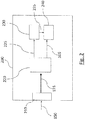
- Fig. 2 shows an embodiment of the present invention for a receiving device 200 for receiving the modified sensor signal 135 from the transmitting device 100.
- the receiving device 200 comprises the following features: an input interface 210, detection unit 220 for detecting a comparison signal 225, an evaluation unit 230 for evaluating the detected comparison signal 225 and an error detector 240.
- the input interface 210 couples to the signal path 150 to receive the modified sensor signal 135.
- the evaluation unit 230 has access to information about a valid comparison signal 125 in order to ascertain an invalidity of the detected comparison signal 225 based on the comparison of the information to the detected comparison signal 225.
- the error detector 240 is configured to detect an error in the transmission of the sensor signal 105 when the detected comparison signal 225 is invalid.
- the receiving device 200 may include a memory that stores information about the valid comparison signal 125. This information may include, for example, the functional history, the period duration, increases and similar information that allow verification of the comparison signal.
- Fig. 3 shows a system with a transmitting device 100 and a receiving device 200, which are connected to each other with a signal path 150, wherein the transmitting device 100 has further optional components.
- the transmitting device 100 may be formed, for example, on a PCB (printed circuit board).
- the transmitting device 100 couples to a first sensor 102a and a second sensor 102b, both of which detect a sensor size to an actuator 101.
- the actuator 101 may be a pedal whose operation or linear movement is to be detected.
- the first sensor 102a detects the actuator quantity by a first signal 105a, which is detected by the transmission device 100.
- the second sensor 102b (or other sensor) detects the same actuator size and outputs a second sensor signal 105b to the transmitter device 100.
- the sensor sizes 105a, 105b of the first sensor 102a and the second sensor 102b are opposite to each other. This means that a greater actuation of the exemplary pedal 101 at the first sensor size 105a, for example, to an increase of the sensor signal while the same operation of the pedal 101 at the second sensor 102b results in a smaller sensor signal.
- the first sensor 102a and the second sensor 102b are configured to generate a respective value range for the first sensor signal 105a and the second sensor signal 105b, which do not overlap each other.
- the two value ranges can be selected such that an average of the sensor values of the first sensor signal 105a and of the second sensor signal 105b lies outside both value ranges.
- the first range of values may range from 4 to 6 volts and the second range of values may range between 10 and 12 volts.
- Such a choice offers the advantage that a short circuit of both sensor signals would lead to a voltage level that is in the range between 7 and 9 volts. Since this range lies outside the two value ranges (between 4 ... 6 V and 10 ... 12 V), the occurrence of such a sensor signal clearly indicates an error.
- the mentioned voltage values are for illustrative purposes only and are not to be construed restrictively. Rather, in other embodiments, these values may be chosen differently.
- the transmitting device 100 has a data processing unit 130 (with a multiplexer 113, an analog-to-digital converter 117 and an optional monitoring unit 170), a signal generator 120, a first time base device 160, an optional second time base device 180 and a digital interface 140.
- a data processing unit 130 (with a multiplexer 113, an analog-to-digital converter 117 and an optional monitoring unit 170), a signal generator 120, a first time base device 160, an optional second time base device 180 and a digital interface 140.
- the signal generator 120 is designed to generate the comparison signal 125, wherein the signal generator 120 is optionally controllable by the data processing unit 130 via a control signal 118.
- the signal generator 120 is configured to generate a periodic comparison signal 125 (for example in the form of a sawtooth pattern or a harmonic oscillation).
- the exemplary periodic signal has, for example, an amplitude in which a value range of the first and / or second sensor signal 105a, 105b is included. This offers the advantage that the comparison signal can check all level values of the sensor signals 105. For a given amplitude, the rate of change of the periodic comparison signal over the Period duration can be set.
- the period of the comparison signal 125 is selected such that as far as possible all digital samples are tested at a given sampling frequency (eg, in that the comparison signal 125 does not change from one sample to the next sample by more than one quantization amount in the digitization).
- a change in the comparison signal 125 is advantageously matched to a digital scan.
- the appropriate control of the signal generator 120 may be via the control signal 118 by the data processing unit 130, i. the amplitude and the period of the comparison signal 125 can be selected by the data processing unit 130 accordingly. However, they should not change dynamically with the sensor signal 105, but be predetermined.
- the comparison signal 125 is input to the multiplexer 113 together with the first sensor signal 105a and the second sensor signal 105b.
- the multiplexer is designed to combine the comparison signal 125 from the signal generator 120, the first sensor signal 105a and the second sensor signal 105b with each other and to pass them on to the analog-to-digital converter 117.
- the analog-to-digital converter 117 is designed to convert the combined signal of the multiplexer 113 into a digital signal 119 and forward it to a further data processing.
- the data processing processes the digitized signal 119 into a modified sensor signal 135 and outputs this to the digital interface 140.
- the digital interface 140 couples to the signal path 150 that connects the transmitting device 100 to the receiving device 200 so that the modified sensor signal 135 is received by the receiving device 200.
- the first time base device 160 may provide a time signal to the data processing unit 130.
- the transmitting device 100 optionally includes the monitoring device 170, which provides monitoring of the processing by the data processing device 130.
- the monitoring device 170 is designed, for example, to detect and signal possible errors in the data processing.
- the second time base device 180 is optionally provided in the transmitting device 100, which provides a second time signal for the monitoring device 170, so that an error in the time base device 160 becomes apparent.
- the data processing unit 130 is configured to process the first sensor signal 105a by a first algorithm 131 (eg in a first calculation unit).
- the data processing unit 130 comprises a second calculation unit for processing the second sensor signal 105b by a second algorithm 132 and a third calculation unit for processing the comparison signal 125 by a third algorithm 133.
- the algorithms include, for example, converting the digitized physical value corresponding, for example, to a path of a pedal into corresponding digital data being transmitted.
- the algorithms may additionally perform offset correction, linearization (e.g., mapping the linear path to a linear signal level), calibration with calibration data.
- the data processing unit 130 includes a combiner 134 configured to combine the obtained results after the calculation / processing by the first to third calculation units 131, 132, 133.
- the combiner 134 may optionally add a checksum and a message counter to the combined result.
- the checksum is configured to provide authenticity of the signals or signal values, while the message counter counts the individual messages, thereby enabling detection of missing or erroneous messages. In particular, this can be used to localize the error.
- a feedback 190 is formed by the data processing unit 130 on the first sensor signal 105a and the second sensor signal 105b.
- one of the two sensor signals can be selectively changed, so that it can be concluded based on the change made, whether the two sensor signals after the analog-to-digital conversion are valid sensor signals or not. For example, can be determined by a targeted change of only one of the two sensor signals 105, whether a short circuit between the two sensor signals 105, there a short circuit would inevitably cause both sensor signals 105 to change, even if only one is varied.
- FIG. 12 shows a flowchart for a method of securely transmitting a sensor signal 105 with respect to a physical quantity according to the present invention.
- the method comprises the steps of: generating S110 a comparison signal 125 that temporally varies over a range of values in a predetermined manner; Combining S120 the sensor signal 105 and the comparison signal 125 to a modified sensor signal 135; Transmitting S130 of the modified sensor signal 135 via a signal path 150; Receiving S140 of the modified sensor signal 135 through a receiver; Detecting S150 of the comparison signal 225 from the modified sensor signal; Comparing S160 of the detected comparison signal 225 with information about a valid comparison signal 125 to determine an invalidation of the detected comparison signal 225 based on a comparison of the information to the detected comparison signal 225; and determining S170 an error in the transmission of the sensor signal 105 when the detected comparison signal 225 is invalid.
- the error can optionally be signaled to a user.
- the method may also be computer implemented, i. it may be implemented by instructions stored on a storage medium and capable of performing the steps of the method when running on a processor.
- the program software code / instructions associated with the flowchart typically include one or more instructions differently stored on different media in or peripheral to a controller (with a processor) that when read and executed by the controller to cause the control unit to perform functions, functions and operations necessary to carry out a method.
- this event can be communicated to a user.
- this event can be communicated to a user.
- the single occurrence of an error only leads to re-transmission of the sensor signal 105, ie the physical Size is recorded again and transmitted. Only when the error persists, this can lead to an error message, so that the user can draw the appropriate consequences.
- the basic concept of the invention is based on a clever division of the monitoring between a sensor unit (with the transmitting device 100) and a central / actuator control unit (with the receiving device 200) and a measurement of an additional, self-generated signal (comparison signal 125) with a known course. This makes it possible to make the sensor element with only one microcontroller "fail silent" capable. With two sensor elements further conceivable errors can be reliably detected by suitable choice of the signal curve.
- the sensor unit includes one or two sensors with analog output signal (sensor signal 105) and a known signal (comparison signal 125), which may have, for example, a sawtooth shape, a sine shape, a PT1 signal, and which is located in the entire signal range of the sensors 101 changes periodically.
- the signal range and the period are known to the sensor device and / or the central / actuator control unit.
- the period duration and the sampling rate can be chosen such that the change from sample to sample is so small that as few values of the A / D converter as possible lie between samples.
- asynchronism ensures that all A / D values occur over a period of time, even if the sampling frequency is chosen so that the value between samples changes by more than one increment. This can be checked whether the calculation was carried out correctly with all possible A / D values.
- the period may be determined by the microcontroller (data processing unit 130) of the sensor control device (transmitting device 100).
- the control signal 118 can be used.
- the signals can be digitized by the microcontroller via an A / D converter (analog-to-digital converter 117) with upstream multiplexer 113. Since the known periodic signal 125 passes through the entire input range periodically, it is possible to test the A / D converter 117 for errors (linearity, absolute value, faulty code, etc.).
- the digitized values can be transmitted to the central / actuator control unit 200 via the interface 140 for further processing.
- the digitized values may also be processed in the microcontroller to a physical value (e.g., a path of a pedal). Subsequently, this value can then be transmitted via the interface to the central / actuator control unit.
- offset processing offset correction
- linearization linearization
- calibration with calibration data or other processing steps can be performed during processing.
- the calibration data on request for example in EOL (end-of-line) test after a change of the sensor unit or the like, when switching on or regularly to the central / for verification / calculation in the central / actuator control unit 200.
- Actuator control unit 200 are transmitted. If the calibration data are stored multiple times in the sensor control unit for safety reasons, all stored calibration data or only the calibrated data that has been checked can be transmitted. In addition, non-volatile storage of the calibration data in the central / actuator control unit 200 can take place. With this a change of the calibration values can be checked. From the change in the calibration values can be concluded that an error or replacement of the sensor unit.
- the processing of the sensor signal 105 and the periodic signal 125 can with same algorithm as the calculation of one of the sensor values. It can thus be ensured that the calculation is carried out correctly over the entire input range (since the course of the periodic signal 125 is known).
- the two sensor signals 105a, 105b can be calculated by different SW (software) parts.
- SW software
- Different implementations may be possible.
- the algorithm may be identical, but the machine code is different due to differently chosen compiler settings. It is also possible that the algorithm is identical, but the implementation is different. It is also possible that the algorithm is different.
- One possibility for different algorithms may be by calculation by a function and calculation by look up table. Another possibility is the use of different functions.
- a check of common mode errors (“common mode” error) of the analog values. This can be done, for example, by having their signals 105a, 105b in opposite directions, i. a change in the size to be measured changes the signal of the two sensors in opposite directions. This makes it possible to detect a corrugated falsification of both sensor values, since an error affecting both signals in the same direction leads to a non-plausible summation signal.
- connection of sensor 105 to the microcontroller 130 is checked. This can be achieved, for example, by designing the sensors 105 such that an invalid value is generated in the event of a short circuit of the signal (eg due to different impedances or different voltage / Current ranges of the sensors).
- the short circuit of the sensor signals can be checked by periodically in each case a sensor signal with a defined signal is changed. Only one sensor signal may change in this test. If both sensor signals change, there is a short circuit.
- the transmission to the controller / actuator is as follows.
- the data is transmitted via a digital interface 140.
- the data can be secured by a check sum and a message counter.
- sensor signal 105a, sensor signal 105b, known signal (comparison signal 125), message counter, checksum (e.g., CRC) are transmitted.
- the test in the controller / actuator 200 is as follows.
- the following functions are performed: check message counter, check the checksum and check the periodic signal (comparison signal 125) with expected course.
- the message counter can be used to narrow the monitoring area.
- the known signal ensures that the values on the interface constantly change. This ensures a check of the processing in the sensor unit and the transmission unit.
Landscapes
- Engineering & Computer Science (AREA)
- Computer Networks & Wireless Communication (AREA)
- Physics & Mathematics (AREA)
- General Physics & Mathematics (AREA)
- Mechanical Engineering (AREA)
- Arrangements For Transmission Of Measured Signals (AREA)
Applications Claiming Priority (2)
| Application Number | Priority Date | Filing Date | Title |
|---|---|---|---|
| DE102014114316.7A DE102014114316A1 (de) | 2014-10-01 | 2014-10-01 | Vorrichtung zum Senden und Empfangen eines Sensorsignals |
| PCT/EP2015/071697 WO2016050558A1 (de) | 2014-10-01 | 2015-09-22 | Vorrichtung zum senden und empfangen eines sensorsignals |
Publications (2)
| Publication Number | Publication Date |
|---|---|
| EP3201894A1 EP3201894A1 (de) | 2017-08-09 |
| EP3201894B1 true EP3201894B1 (de) | 2018-09-12 |
Family
ID=54199191
Family Applications (1)
| Application Number | Title | Priority Date | Filing Date |
|---|---|---|---|
| EP15770840.5A Active EP3201894B1 (de) | 2014-10-01 | 2015-09-22 | Vorrichtung zum senden und empfangen eines sensorsignals |
Country Status (6)
| Country | Link |
|---|---|
| US (1) | US10003864B2 (pt) |
| EP (1) | EP3201894B1 (pt) |
| CN (1) | CN107005753B (pt) |
| BR (1) | BR112017006740B1 (pt) |
| DE (1) | DE102014114316A1 (pt) |
| WO (1) | WO2016050558A1 (pt) |
Families Citing this family (10)
| Publication number | Priority date | Publication date | Assignee | Title |
|---|---|---|---|---|
| US10243724B2 (en) * | 2014-02-12 | 2019-03-26 | Infineon Technologies Ag | Sensor subassembly and method for sending a data signal |
| US10354501B2 (en) * | 2016-11-08 | 2019-07-16 | The Boeing Company | Autonomous, low energy, access indication system |
| CH714256A1 (de) * | 2017-10-18 | 2019-04-30 | Elesta Gmbh Ostfildern De Zweigniederlassung Bad Ragaz | Verfahren zur seriellen Übermittlung von Daten eines Sensors an ein Sicherheitskontrollgerät. |
| DE102018122881A1 (de) * | 2018-09-18 | 2020-03-19 | Knorr-Bremse Systeme für Nutzfahrzeuge GmbH | Verfahren zum Übertragen von Sensorsignalen von Sensoren einer Fahrzeugbremse und Fahrzeugbremse mit Sensoranordnung mit mindestens zwei Sensoren |
| US10674365B1 (en) * | 2019-09-26 | 2020-06-02 | OpenPath Security Inc. | Systems and methods for preventing relay attacks |
| US11590984B2 (en) | 2019-10-14 | 2023-02-28 | Bendix Commercial Vehicle Systems Llc | Control system for operator controlled vehicle subsystems |
| DE102019132278A1 (de) | 2019-11-28 | 2021-06-02 | Infineon Technologies Ag | Sensorvorrichtung, Steuerung sowie Verfahren zur Kommunikation zwischen einer Sensorvorrichtung und einer Steuerung |
| DE102021105234A1 (de) | 2021-03-04 | 2022-09-08 | HELLA GmbH & Co. KGaA | Verfahren zum Kommunizieren von Informationen, Empfängervorrichtung, Sensorvorrichtung sowie System |
| EP4228187B1 (en) * | 2022-02-15 | 2024-06-19 | Aptiv Technologies AG | Integrity tests for mixed analog digital systems |
| CN114205175A (zh) * | 2022-02-19 | 2022-03-18 | 深圳市三江电气有限公司 | 一种多传感器感知数据传输过程中自检修改系统 |
Family Cites Families (12)
| Publication number | Priority date | Publication date | Assignee | Title |
|---|---|---|---|---|
| DE4004085A1 (de) | 1990-02-10 | 1991-08-14 | Bosch Gmbh Robert | Verfahren und einrichtung zur elektronischen steuerung und/oder regelung einer brennkraftmaschine eines kraftfahrzeugs |
| DE4235880C2 (de) * | 1992-10-23 | 2003-07-17 | Bosch Gmbh Robert | Verfahren und Vorrichtung zur Erfassung einer veränderlichen Größe bei Fahrzeugen |
| DE20121466U1 (de) * | 2001-07-26 | 2003-02-27 | Bayerische Motoren Werke AG, 80809 München | Taktsynchronisation in einem verteilen System |
| ATE367700T1 (de) * | 2002-04-16 | 2007-08-15 | Bosch Gmbh Robert | Verfahren und einheit zur bitstromdekodierung |
| DE10362049B9 (de) * | 2003-08-12 | 2018-05-03 | Infineon Technologies Ag | In-Betrieb-Test eines Signalpfades |
| US20070135983A1 (en) * | 2005-12-12 | 2007-06-14 | Automotive Systems Laboratory, Inc. | Initialization process for an occupant classification initialization |
| DE102008041339B4 (de) * | 2008-08-19 | 2020-06-04 | Robert Bosch Gmbh | Steuergerät und Verfahren zur Ansteuerung von Personenschutzmitteln für ein Fahrzeug |
| CN102455288B (zh) * | 2010-10-15 | 2014-10-15 | 西门子公司 | 通过在线信号电平监控对传感器装置的光电信号路径进行校准 |
| DE102011052095B4 (de) | 2011-07-25 | 2013-08-01 | Leuze Electronic Gmbh & Co. Kg | Busanschaltung zum Anschluss eines Sicherheitssensors an ein AS-i Bussystem |
| DE102012201170A1 (de) * | 2012-01-27 | 2013-08-01 | Dr. Johannes Heidenhain Gmbh | Vorrichtung zur Übertragung von Sensordaten |
| DE102012223271A1 (de) * | 2012-12-14 | 2014-06-18 | Siemens Aktiengesellschaft | Anordnung mit einem Aktuator |
| DE102013221583A1 (de) * | 2013-10-24 | 2015-04-30 | Robert Bosch Gmbh | Batterie mit einer Vorrichtung zur digitalen Übertragung von Strom-Messwerten, Batteriesteuerung mit einer Vorrichtung zum Empfangen einer digitalen Übertragung von Strom-Messwerten, sowie Verfahren zur gesicherten digitalen Übertragung von Strom-Messwerten. |
-
2014
- 2014-10-01 DE DE102014114316.7A patent/DE102014114316A1/de active Pending
-
2015
- 2015-09-22 CN CN201580065175.3A patent/CN107005753B/zh active Active
- 2015-09-22 WO PCT/EP2015/071697 patent/WO2016050558A1/de active Application Filing
- 2015-09-22 US US15/516,232 patent/US10003864B2/en active Active
- 2015-09-22 EP EP15770840.5A patent/EP3201894B1/de active Active
- 2015-09-22 BR BR112017006740-4A patent/BR112017006740B1/pt active IP Right Grant
Non-Patent Citations (1)
| Title |
|---|
| None * |
Also Published As
| Publication number | Publication date |
|---|---|
| WO2016050558A1 (de) | 2016-04-07 |
| CN107005753B (zh) | 2020-09-04 |
| CN107005753A (zh) | 2017-08-01 |
| US20170303015A1 (en) | 2017-10-19 |
| BR112017006740B1 (pt) | 2023-10-17 |
| US10003864B2 (en) | 2018-06-19 |
| EP3201894A1 (de) | 2017-08-09 |
| DE102014114316A1 (de) | 2016-04-07 |
| BR112017006740A2 (pt) | 2017-12-19 |
Similar Documents
| Publication | Publication Date | Title |
|---|---|---|
| EP3201894B1 (de) | Vorrichtung zum senden und empfangen eines sensorsignals | |
| EP2526431B1 (de) | Verfahren und vorrichtung zur überwachung eines frequenzsignals | |
| DE102006017302B4 (de) | Verfahren und System zur Kontrolle einer Signalübertragung eines elektrischen Pedals | |
| DE10162689A1 (de) | Vorrichtung zur Überwachung von in einem Fahrzeug angeordneten Sensormitteln | |
| DE102017219448B4 (de) | Signalprotokoll-Störungserkennungssystem und -verfahren | |
| EP2613463B1 (de) | Verfahren zur überwachung eines transmitters und entsprechender transmitter | |
| DE102008057474B4 (de) | Meßumformer | |
| WO2006092182A1 (de) | Verfahren und vorrichtung zur überwachung einer prozessausführung | |
| EP3024707A1 (de) | Verfahren und elektronische schaltungsanordnung zur redundanten signalverarbeitung einer sicherheitsrelevanten anwendung, kraftfahrzeugbremssystem und kraftfahrzeug damit sowie verwendung einer derartigen elektronischen schaltungsanordnung | |
| WO2013041296A1 (de) | Verfahren und vorrichtung zum koppeln eines ersten sensors mit zumindest einem zweiten sensor | |
| EP2339415A2 (de) | Steuersystem für Baumaschinen und Verfahren zum Betrieb des Steuersystems | |
| DE10392545B4 (de) | Elektronische Schaltungsanordnung zur fehlerabgesicherten Analog-/Digital-Umwandlung von Signalen | |
| WO2013020529A1 (de) | Messwert-übertragungsvorrichtung | |
| DE102015218294A1 (de) | Sensorsystem mit Sicherheitsmechanismus | |
| DE102018217118B4 (de) | Verfahren zum Erstellen einer Fehlerdiagnose eines Antriebsstrangs eines elektrisch betriebenen Kraftfahrzeugs und Kraftfahrzeug | |
| EP2394400B1 (de) | Konfigurierbare statusverarbeitungseinheit für sensor-aktor-systeme | |
| DE102017103418B4 (de) | Verfahren zum Bestimmen von Informationen über eine Integrität von Signalverarbeitungskomponenten innerhalb eines Signalpfades, Signalverarbeitungsschaltung und elektronische Steuerungseinheit | |
| EP2622418B1 (de) | Schaltungsanordnung und verfahren zur überwachung eines dsps im rahmen einer sicherheitskritischen anwendung | |
| EP2539782B1 (de) | Verfahren zur erfassung von in einer elektronisch gesteuerten produktionsmaschine auftretenden ereignissen | |
| DE102017200280B4 (de) | Verfahren und Vorrichtung zum Qualifizieren eines Fehlers eines Sensors mittels einer Statusinformation | |
| EP3672846B1 (de) | Vorrichtung und verfahren zum übertragen einer physikalischen grösse unter verwendung von analogen signalen für eine fahrzeugsteuerung | |
| DE202006016012U1 (de) | Systemarchitektur für eine Firmware | |
| DE102022110952A1 (de) | Antriebssystem für ein Fahrzeug | |
| WO2022117660A1 (de) | Verfahren und vorrichtung zum absichern eines signals zur übertragung eines messwertes an eine signalverarbeitungseinheit | |
| WO2022184552A1 (de) | Verfahren zum kommunizieren von informationen, empfängervorrichtung, sensorvorrichtung sowie system |
Legal Events
| Date | Code | Title | Description |
|---|---|---|---|
| PUAI | Public reference made under article 153(3) epc to a published international application that has entered the european phase |
Free format text: ORIGINAL CODE: 0009012 |
|
| 17P | Request for examination filed |
Effective date: 20170502 |
|
| AK | Designated contracting states |
Kind code of ref document: A1 Designated state(s): AL AT BE BG CH CY CZ DE DK EE ES FI FR GB GR HR HU IE IS IT LI LT LU LV MC MK MT NL NO PL PT RO RS SE SI SK SM TR |
|
| AX | Request for extension of the european patent |
Extension state: BA ME |
|
| DAV | Request for validation of the european patent (deleted) | ||
| DAX | Request for extension of the european patent (deleted) | ||
| GRAP | Despatch of communication of intention to grant a patent |
Free format text: ORIGINAL CODE: EPIDOSNIGR1 |
|
| INTG | Intention to grant announced |
Effective date: 20180406 |
|
| GRAS | Grant fee paid |
Free format text: ORIGINAL CODE: EPIDOSNIGR3 |
|
| GRAA | (expected) grant |
Free format text: ORIGINAL CODE: 0009210 |
|
| AK | Designated contracting states |
Kind code of ref document: B1 Designated state(s): AL AT BE BG CH CY CZ DE DK EE ES FI FR GB GR HR HU IE IS IT LI LT LU LV MC MK MT NL NO PL PT RO RS SE SI SK SM TR |
|
| REG | Reference to a national code |
Ref country code: GB Ref legal event code: FG4D Free format text: NOT ENGLISH |
|
| REG | Reference to a national code |
Ref country code: CH Ref legal event code: EP |
|
| REG | Reference to a national code |
Ref country code: IE Ref legal event code: FG4D Free format text: LANGUAGE OF EP DOCUMENT: GERMAN |
|
| REG | Reference to a national code |
Ref country code: DE Ref legal event code: R096 Ref document number: 502015005885 Country of ref document: DE |
|
| REG | Reference to a national code |
Ref country code: AT Ref legal event code: REF Ref document number: 1041509 Country of ref document: AT Kind code of ref document: T Effective date: 20181015 |
|
| REG | Reference to a national code |
Ref country code: SE Ref legal event code: TRGR |
|
| REG | Reference to a national code |
Ref country code: NL Ref legal event code: MP Effective date: 20180912 |
|
| REG | Reference to a national code |
Ref country code: LT Ref legal event code: MG4D |
|
| PG25 | Lapsed in a contracting state [announced via postgrant information from national office to epo] |
Ref country code: LT Free format text: LAPSE BECAUSE OF FAILURE TO SUBMIT A TRANSLATION OF THE DESCRIPTION OR TO PAY THE FEE WITHIN THE PRESCRIBED TIME-LIMIT Effective date: 20180912 Ref country code: BG Free format text: LAPSE BECAUSE OF FAILURE TO SUBMIT A TRANSLATION OF THE DESCRIPTION OR TO PAY THE FEE WITHIN THE PRESCRIBED TIME-LIMIT Effective date: 20181212 Ref country code: FI Free format text: LAPSE BECAUSE OF FAILURE TO SUBMIT A TRANSLATION OF THE DESCRIPTION OR TO PAY THE FEE WITHIN THE PRESCRIBED TIME-LIMIT Effective date: 20180912 Ref country code: NO Free format text: LAPSE BECAUSE OF FAILURE TO SUBMIT A TRANSLATION OF THE DESCRIPTION OR TO PAY THE FEE WITHIN THE PRESCRIBED TIME-LIMIT Effective date: 20181212 Ref country code: GR Free format text: LAPSE BECAUSE OF FAILURE TO SUBMIT A TRANSLATION OF THE DESCRIPTION OR TO PAY THE FEE WITHIN THE PRESCRIBED TIME-LIMIT Effective date: 20181213 Ref country code: RS Free format text: LAPSE BECAUSE OF FAILURE TO SUBMIT A TRANSLATION OF THE DESCRIPTION OR TO PAY THE FEE WITHIN THE PRESCRIBED TIME-LIMIT Effective date: 20180912 |
|
| PG25 | Lapsed in a contracting state [announced via postgrant information from national office to epo] |
Ref country code: HR Free format text: LAPSE BECAUSE OF FAILURE TO SUBMIT A TRANSLATION OF THE DESCRIPTION OR TO PAY THE FEE WITHIN THE PRESCRIBED TIME-LIMIT Effective date: 20180912 Ref country code: LV Free format text: LAPSE BECAUSE OF FAILURE TO SUBMIT A TRANSLATION OF THE DESCRIPTION OR TO PAY THE FEE WITHIN THE PRESCRIBED TIME-LIMIT Effective date: 20180912 Ref country code: AL Free format text: LAPSE BECAUSE OF FAILURE TO SUBMIT A TRANSLATION OF THE DESCRIPTION OR TO PAY THE FEE WITHIN THE PRESCRIBED TIME-LIMIT Effective date: 20180912 |
|
| PG25 | Lapsed in a contracting state [announced via postgrant information from national office to epo] |
Ref country code: CZ Free format text: LAPSE BECAUSE OF FAILURE TO SUBMIT A TRANSLATION OF THE DESCRIPTION OR TO PAY THE FEE WITHIN THE PRESCRIBED TIME-LIMIT Effective date: 20180912 Ref country code: RO Free format text: LAPSE BECAUSE OF FAILURE TO SUBMIT A TRANSLATION OF THE DESCRIPTION OR TO PAY THE FEE WITHIN THE PRESCRIBED TIME-LIMIT Effective date: 20180912 Ref country code: ES Free format text: LAPSE BECAUSE OF FAILURE TO SUBMIT A TRANSLATION OF THE DESCRIPTION OR TO PAY THE FEE WITHIN THE PRESCRIBED TIME-LIMIT Effective date: 20180912 Ref country code: PL Free format text: LAPSE BECAUSE OF FAILURE TO SUBMIT A TRANSLATION OF THE DESCRIPTION OR TO PAY THE FEE WITHIN THE PRESCRIBED TIME-LIMIT Effective date: 20180912 Ref country code: NL Free format text: LAPSE BECAUSE OF FAILURE TO SUBMIT A TRANSLATION OF THE DESCRIPTION OR TO PAY THE FEE WITHIN THE PRESCRIBED TIME-LIMIT Effective date: 20180912 Ref country code: IS Free format text: LAPSE BECAUSE OF FAILURE TO SUBMIT A TRANSLATION OF THE DESCRIPTION OR TO PAY THE FEE WITHIN THE PRESCRIBED TIME-LIMIT Effective date: 20190112 Ref country code: EE Free format text: LAPSE BECAUSE OF FAILURE TO SUBMIT A TRANSLATION OF THE DESCRIPTION OR TO PAY THE FEE WITHIN THE PRESCRIBED TIME-LIMIT Effective date: 20180912 |
|
| REG | Reference to a national code |
Ref country code: CH Ref legal event code: PL |
|
| PG25 | Lapsed in a contracting state [announced via postgrant information from national office to epo] |
Ref country code: PT Free format text: LAPSE BECAUSE OF FAILURE TO SUBMIT A TRANSLATION OF THE DESCRIPTION OR TO PAY THE FEE WITHIN THE PRESCRIBED TIME-LIMIT Effective date: 20190112 Ref country code: SM Free format text: LAPSE BECAUSE OF FAILURE TO SUBMIT A TRANSLATION OF THE DESCRIPTION OR TO PAY THE FEE WITHIN THE PRESCRIBED TIME-LIMIT Effective date: 20180912 Ref country code: SK Free format text: LAPSE BECAUSE OF FAILURE TO SUBMIT A TRANSLATION OF THE DESCRIPTION OR TO PAY THE FEE WITHIN THE PRESCRIBED TIME-LIMIT Effective date: 20180912 |
|
| REG | Reference to a national code |
Ref country code: BE Ref legal event code: MM Effective date: 20180930 |
|
| REG | Reference to a national code |
Ref country code: DE Ref legal event code: R097 Ref document number: 502015005885 Country of ref document: DE |
|
| REG | Reference to a national code |
Ref country code: IE Ref legal event code: MM4A |
|
| PG25 | Lapsed in a contracting state [announced via postgrant information from national office to epo] |
Ref country code: LU Free format text: LAPSE BECAUSE OF NON-PAYMENT OF DUE FEES Effective date: 20180922 |
|
| PLBE | No opposition filed within time limit |
Free format text: ORIGINAL CODE: 0009261 |
|
| STAA | Information on the status of an ep patent application or granted ep patent |
Free format text: STATUS: NO OPPOSITION FILED WITHIN TIME LIMIT |
|
| PG25 | Lapsed in a contracting state [announced via postgrant information from national office to epo] |
Ref country code: IE Free format text: LAPSE BECAUSE OF NON-PAYMENT OF DUE FEES Effective date: 20180922 Ref country code: DK Free format text: LAPSE BECAUSE OF FAILURE TO SUBMIT A TRANSLATION OF THE DESCRIPTION OR TO PAY THE FEE WITHIN THE PRESCRIBED TIME-LIMIT Effective date: 20180912 Ref country code: MC Free format text: LAPSE BECAUSE OF FAILURE TO SUBMIT A TRANSLATION OF THE DESCRIPTION OR TO PAY THE FEE WITHIN THE PRESCRIBED TIME-LIMIT Effective date: 20180912 |
|
| 26N | No opposition filed |
Effective date: 20190613 |
|
| PG25 | Lapsed in a contracting state [announced via postgrant information from national office to epo] |
Ref country code: BE Free format text: LAPSE BECAUSE OF NON-PAYMENT OF DUE FEES Effective date: 20180930 Ref country code: SI Free format text: LAPSE BECAUSE OF FAILURE TO SUBMIT A TRANSLATION OF THE DESCRIPTION OR TO PAY THE FEE WITHIN THE PRESCRIBED TIME-LIMIT Effective date: 20180912 Ref country code: LI Free format text: LAPSE BECAUSE OF NON-PAYMENT OF DUE FEES Effective date: 20180930 Ref country code: CH Free format text: LAPSE BECAUSE OF NON-PAYMENT OF DUE FEES Effective date: 20180930 |
|
| PG25 | Lapsed in a contracting state [announced via postgrant information from national office to epo] |
Ref country code: FR Free format text: LAPSE BECAUSE OF NON-PAYMENT OF DUE FEES Effective date: 20181112 |
|
| PG25 | Lapsed in a contracting state [announced via postgrant information from national office to epo] |
Ref country code: MT Free format text: LAPSE BECAUSE OF FAILURE TO SUBMIT A TRANSLATION OF THE DESCRIPTION OR TO PAY THE FEE WITHIN THE PRESCRIBED TIME-LIMIT Effective date: 20180912 |
|
| PG25 | Lapsed in a contracting state [announced via postgrant information from national office to epo] |
Ref country code: TR Free format text: LAPSE BECAUSE OF FAILURE TO SUBMIT A TRANSLATION OF THE DESCRIPTION OR TO PAY THE FEE WITHIN THE PRESCRIBED TIME-LIMIT Effective date: 20180912 |
|
| PG25 | Lapsed in a contracting state [announced via postgrant information from national office to epo] |
Ref country code: HU Free format text: LAPSE BECAUSE OF FAILURE TO SUBMIT A TRANSLATION OF THE DESCRIPTION OR TO PAY THE FEE WITHIN THE PRESCRIBED TIME-LIMIT; INVALID AB INITIO Effective date: 20150922 Ref country code: CY Free format text: LAPSE BECAUSE OF FAILURE TO SUBMIT A TRANSLATION OF THE DESCRIPTION OR TO PAY THE FEE WITHIN THE PRESCRIBED TIME-LIMIT Effective date: 20180912 Ref country code: MK Free format text: LAPSE BECAUSE OF NON-PAYMENT OF DUE FEES Effective date: 20180912 |
|
| GBPC | Gb: european patent ceased through non-payment of renewal fee |
Effective date: 20190922 |
|
| PG25 | Lapsed in a contracting state [announced via postgrant information from national office to epo] |
Ref country code: GB Free format text: LAPSE BECAUSE OF NON-PAYMENT OF DUE FEES Effective date: 20190922 |
|
| REG | Reference to a national code |
Ref country code: AT Ref legal event code: MM01 Ref document number: 1041509 Country of ref document: AT Kind code of ref document: T Effective date: 20200922 |
|
| PG25 | Lapsed in a contracting state [announced via postgrant information from national office to epo] |
Ref country code: AT Free format text: LAPSE BECAUSE OF NON-PAYMENT OF DUE FEES Effective date: 20200922 |
|
| P01 | Opt-out of the competence of the unified patent court (upc) registered |
Effective date: 20230508 |
|
| PGFP | Annual fee paid to national office [announced via postgrant information from national office to epo] |
Ref country code: SE Payment date: 20230921 Year of fee payment: 9 Ref country code: DE Payment date: 20230919 Year of fee payment: 9 |
|
| PGFP | Annual fee paid to national office [announced via postgrant information from national office to epo] |
Ref country code: IT Payment date: 20230929 Year of fee payment: 9 |