EP3201893B1 - Fernsteuerungsvorrichtung, benutzergerät und system dafür sowie verfahren, computerprogrammprodukt - Google Patents
Fernsteuerungsvorrichtung, benutzergerät und system dafür sowie verfahren, computerprogrammprodukt Download PDFInfo
- Publication number
- EP3201893B1 EP3201893B1 EP15770890.0A EP15770890A EP3201893B1 EP 3201893 B1 EP3201893 B1 EP 3201893B1 EP 15770890 A EP15770890 A EP 15770890A EP 3201893 B1 EP3201893 B1 EP 3201893B1
- Authority
- EP
- European Patent Office
- Prior art keywords
- signal
- fragment
- optical
- remote control
- fragments
- Prior art date
- Legal status (The legal status is an assumption and is not a legal conclusion. Google has not performed a legal analysis and makes no representation as to the accuracy of the status listed.)
- Active
Links
Images


Classifications
-
- G—PHYSICS
- G08—SIGNALLING
- G08C—TRANSMISSION SYSTEMS FOR MEASURED VALUES, CONTROL OR SIMILAR SIGNALS
- G08C17/00—Arrangements for transmitting signals characterised by the use of a wireless electrical link
-
- G—PHYSICS
- G06—COMPUTING OR CALCULATING; COUNTING
- G06F—ELECTRIC DIGITAL DATA PROCESSING
- G06F3/00—Input arrangements for transferring data to be processed into a form capable of being handled by the computer; Output arrangements for transferring data from processing unit to output unit, e.g. interface arrangements
- G06F3/01—Input arrangements or combined input and output arrangements for interaction between user and computer
- G06F3/03—Arrangements for converting the position or the displacement of a member into a coded form
- G06F3/0304—Detection arrangements using opto-electronic means
-
- G—PHYSICS
- G08—SIGNALLING
- G08C—TRANSMISSION SYSTEMS FOR MEASURED VALUES, CONTROL OR SIMILAR SIGNALS
- G08C23/00—Non-electrical signal transmission systems, e.g. optical systems
- G08C23/04—Non-electrical signal transmission systems, e.g. optical systems using light waves, e.g. infrared
-
- H—ELECTRICITY
- H05—ELECTRIC TECHNIQUES NOT OTHERWISE PROVIDED FOR
- H05B—ELECTRIC HEATING; ELECTRIC LIGHT SOURCES NOT OTHERWISE PROVIDED FOR; CIRCUIT ARRANGEMENTS FOR ELECTRIC LIGHT SOURCES, IN GENERAL
- H05B47/00—Circuit arrangements for operating light sources in general, i.e. where the type of light source is not relevant
- H05B47/10—Controlling the light source
- H05B47/175—Controlling the light source by remote control
- H05B47/19—Controlling the light source by remote control via wireless transmission
-
- H—ELECTRICITY
- H05—ELECTRIC TECHNIQUES NOT OTHERWISE PROVIDED FOR
- H05B—ELECTRIC HEATING; ELECTRIC LIGHT SOURCES NOT OTHERWISE PROVIDED FOR; CIRCUIT ARRANGEMENTS FOR ELECTRIC LIGHT SOURCES, IN GENERAL
- H05B47/00—Circuit arrangements for operating light sources in general, i.e. where the type of light source is not relevant
- H05B47/10—Controlling the light source
- H05B47/175—Controlling the light source by remote control
- H05B47/196—Controlling the light source by remote control characterised by user interface arrangements
-
- G—PHYSICS
- G08—SIGNALLING
- G08C—TRANSMISSION SYSTEMS FOR MEASURED VALUES, CONTROL OR SIMILAR SIGNALS
- G08C2201/00—Transmission systems of control signals via wireless link
- G08C2201/20—Binding and programming of remote control devices
-
- G—PHYSICS
- G08—SIGNALLING
- G08C—TRANSMISSION SYSTEMS FOR MEASURED VALUES, CONTROL OR SIMILAR SIGNALS
- G08C2201/00—Transmission systems of control signals via wireless link
- G08C2201/70—Device selection
- G08C2201/71—Directional beams
-
- G—PHYSICS
- G08—SIGNALLING
- G08C—TRANSMISSION SYSTEMS FOR MEASURED VALUES, CONTROL OR SIMILAR SIGNALS
- G08C2201/00—Transmission systems of control signals via wireless link
- G08C2201/90—Additional features
- G08C2201/92—Universal remote control
Definitions
- the present invention is directed at a remote control device for controlling one or more user devices, comprising a directional optical sensor for receiving one or more optical signals from the user devices.
- the invention is further directed at a user device arranged for being operated by means of a remote control device as described, wherein the user device comprises an optical transmitter for transmitting an optical signal, and a modulator cooperating with the optical transmitter for modulating the optical signal.
- the invention is further directed at a method of operating a remote control device, a method of composing an optical signal for identification in a user device, and computer program products for performing such methods.
- the invention relates to an optical identification signal.
- a known problem is that the number of different remote control devices in a traditional setup corresponds with the number of remotely controllable devices present in the room, i.e. each device has its own remote controller. To users this is experienced as a nuisance, e.g. having to find the correct remote controller or requiring to understand all the functions that are available for control.
- This has led to the integration of control functions for various devices into one controller, and the development of universal controllers that can be programmed to be associated with various devices. With the wide spreading and development of smart phones and tablets, such functions may nowadays be controlled via applications with dedicated menus.
- Some remote controllers are nowadays available that allow selection of a to-be-controlled user device by means of pointing to the device.
- An example of such a remote controller device is described in International patent application WO 2006/079939 .
- This document describes a pointing device that can be pointed at user device to-be-controlled, and that sends triggers targeted to each device sequentially to cause these devices to send a visual identifier.
- the system described assists in overcoming some of the above described issues, although some user action is required to target the desired device for triggering.
- a remote control device for controlling one or more user devices, comprising a directional optical sensor for receiving one or more optical signals from the user devices and for detecting an incoming direction of said received optical signals, and a processor, wherein, for identification of at least one of said user devices, the processor is arranged for analyzing at least one of said received optical signals for associating thereof with the at least one of said user devices and for keeping track of the at least one of said optical signals upon changing of said incoming direction, wherein the one or more optical signals comprise high and low signal states, and wherein each optical signal consists of one or more signal fragments, each signal fragment comprising a leading or trailing low signal state and a high signal state, wherein a duration of the high signal state determines a signal fragment type of the signal fragment and wherein said duration of the high signal state is longer than a duration of the low signal state, and wherein the processor is arranged for performing said associating of said at least one received optical signal with the at least one of said user devices by recognition of the
- the remote control device of the present invention applies a directional optical sensor for receiving optical signals transmitted by user devices with which the remote control device has a direct line of sight.
- the optical sensor is directional in the sense that it is able to establish an incoming direction or differences between incoming directions of received optical signals.
- the directional optical sensor allows to establish an angle between the incoming direction of the received optical signal and e.g. the central axis perpendicular to the sensor surface.
- the optical sensor provides an image of the field of view from which positional coordinates of a received optical signal can be derived, indicating the relative location of the source of the incoming optical signal with respect to the sensor.
- the remote control device allows a user to point the device in a direction of a user device comprising an optical transmitter, and receive the optical signal transmitted by the device as well as its relative location with respect to the remote control device.
- the remote control device of the present invention may for example use this incoming direction for establishing which device the user is pointing at, and thereby selecting an optical signal from the received optical signals as being the optical signal belonging to the device of interest.
- the optical signal being closest to image sensor center or having the smallest angle with the transverse central axis through the sensor surface may be considered as belonging to the device pointed at by the user.
- selection of an optical signal based on the information on the incoming direction of the signal may be performed differently, e.g. by selecting multiple optical signals.
- the processor is arranged for associating the at least one received optical signal with the at least one of said user devices.
- the processor of the remote control device has to keep track of the optical signal such as to enable analysis thereof for identification of an associated user device.
- a user's hand is in practice not steady, and the incoming direction of the optical signal is thus changing continuously.
- To enable associating the optical signal with a corresponding device it is important that the signal does not get lost, e.g. because the remote controller may loose track as a result of the constant change of incoming direction.
- the received optical signals from the user devices comprise high and low signal states, for example high and low optical intensities.
- Each optical signal consists of one or more signal fragments, and each signal fragment comprises a leading or trailing low signal state and a high signal state.
- the duration of the high signal state determines a signal fragment type of the signal fragment; this could be a specific value of the signal fragment or a bit combination, or it could be an indication that the fragment resembles a header or trailer fragment.
- the processor obtains a signal pattern from the at least one of said received optical signals which is uniquely associable with said at least one of said user devices.
- the duration (at least during transmission of identification information) of the high signal state is longer than a duration of the low signal state.
- the optical signals established in this way are optimized for being 'followable' by the remote control device. This is due to the fact that low states cannot be followed as there is no light. For example, if the optical signal is an on-off modulated optical signal, it is important that the provided optical signal consists mainly of 'on' states with only few 'off states. This is due to the fact that the optical signal can be easily followed as long as it is in 'on' state (or high signal state). However, while being in the 'off state, the remote control loses track of the signal.
- leading or trailing low signal states of the signal fragments are of a fixed duration. This fixed duration may be minimized with respect to said duration of said high signal state.
- the duration of the low signal state of each signal fragment may be only just sufficiently long for enabling detection of the low signal state by the remote control device.
- the payload information carried within each signal fraction is coded in the duration of the high signal state, the duration of which differs with the type of signal fragment.
- the processor is arranged for detecting the low signal states for distinguishing said one or more signal fragments from each other within the at least one received optical signal. Each time a low signal state is detected, the remote controller is made aware of a next signal fragment being received.
- the processor By determining the duration of the high signal state, the processor is able to determine the signal fragment type, telling the processor whether it has received a header, trailer, or payload data type of signal fragment.
- the latter could include a particular value, bit or bit combination encoded in the length (i.e. duration) of the high signal state.
- the received optical signals represent binary signals formed of sequences of bits, wherein for each signal fragment the high signal states are formed of one or more high bits and the low signal states are formed of at least one low bit.
- the high signal states could be bit value '1', while the low signal states could be bit value '0'.
- a signal fragment could thus for example be formed of a leading or trailing low signal state of fixed duration and a high signal state of a length corresponding with a desired signal fragment type, and could thus for example be resembled by '011111', or '111110', or even '0111110'.
- the number of consecutive bits herein relates to a given signal fragment type, e.g. a header signal fragment.
- signal fragment types could for example relate to fragment values encoded by the number of consecutive 1's in the fragment.
- the value may encode a bit pair of an identifier (e.g. '00', '01', '10', '11').
- Value '00' could be encoded by a single '1' in the signal fragment, which would yield a signal fragment: '01' (or '10', or '010').
- Value '01' could be encoded by a two consecutive 1's in the signal fragment, which would yield a signal fragment: '011' (or '110', or '0110').
- Value '10' could be encoded by a three consecutive 1's in the signal fragment, which would yield a signal fragment: '0111' (or '1110', or '01110').
- Value '11' could be encoded by a four consecutive 1's in the signal fragment, which would yield a signal fragment: '01111' (or '11110', or '011110').
- the trailer signal fragment may be simply '0', or could even be absent as long as the header can be recognized (for the same reason, suppose the signal fragments include a recognizable trailer, then the header could be absent).
- a unique identifier number of the user device e.g. '11011001' (decimal: 217) would thus render the combination '11'-'01'-'10'-'01'.
- the corresponding signal fragments would thus be the header '011111' followed by '01111', '011', '0111', and '011', and the trailer '0'. This yields the full signal: '0111110111101101110110' (total length: 22 bits).
- a different unique identifier e.g. '01000001' (decimal: 65) would yield a full signal: '01111101101010110' (total length: 17 bits).
- the total signal likewise is of different length.
- the processor is arranged for determining the number of consecutive high bits from each signal fragment, and for determining the signal fragment type from the number of high bits.
- the directional optical sensor of the remote control device may be a camera providing image frames at a given frame rate to the processor
- a single bit in the optical signal may be set to endure predefined but at least three consecutive image frames. This allows for larger clock offsets and relaxed timing jitter (could be different for low and hi signal states and in between packet spaces).
- the processor is able to establish the number of consecutive 1's in the signal fragment. Thereby, the processor can establish whether the received signal fragment is a header, a trailer, or a payload signal fragment representing a specific value.
- the processor of the remote control device is arranged for converting the signal fragment type into a signal fragment value, and for combining the signal fragment values of one or more signal fragments for obtaining a binary identifier associated with the at least one of said user devices.
- a possible manner of encoding has been extensively described above, and the logic therein may be applied for decoding the received signal fragments and establishing their types and values.
- the processor is arranged for selecting the at least one of said received optical signals for analyzing thereof, wherein the selection is dependent on a detected incoming direction of said received optical signals.
- the selection may be performed either before, during or after the processor performs the analysis of the at least one optical signal, whichever implementation is desired. In some embodiments, selection may be performed prior to analysis, allowing the processor to focus on only one optical signal being tracked. In other embodiments, the processor analyses all received optical signals and also keeps track of them, and thereafter selects one or more optical signals of interest while discarding other received optical signals.
- the remote control device further comprises input means for receiving input from a user and a transmitter for transmitting control commands to the identified at least one of said user devices for control thereof by the user.
- the remote control device may be enabled to switch to a control module which is designed for controlling the selected device.
- a control module may for example include a user interfaces and control commands that may be stored in a memory of the remote control device, or could be embodied in different hardware or software coded control modules that are either external to the remote control device or integrated therein.
- the further steps of receiving user input and transmitting a control command may be implemented using standard protocols.
- the remote control device may include other elements, such as a display screen for displaying information or a user interface.
- the input means could include a touch sensitive display screen wherein input and output functions are combined.
- input may also be obtained via gesture detection e.g. based on camera data or motion sensor data, e.g. received from a motion sensor (not shown) like for instance an accelerometer (not shown).
- the directional optical sensor is a camera for providing images to the processor for performing said analysis.
- the directional optical sensor comprises a suitable arrangement or grouping of p-i-n photodiodes (shortly: PIN diodes) which allows to establish the incoming direction of received optical signals.
- a user device arranged for being operated by means of a remote control device in accordance with the first aspect, wherein the user device comprises an optical transmitter for transmitting an optical signal, and a modulator cooperating with the optical transmitter for modulating the optical signal such that it comprises high and low signal states, and such that each optical signal consists of one or more signal fragments, each signal fragment comprising a leading or trailing low signal state and a high signal state, wherein a duration of the high signal state determines a signal fragment type of the signal fragment and wherein said duration of the high signal state is longer than a duration of the low signal state, the user device further comprising a controller cooperating with the modulator for enabling modulation of the optical signal in accordance with a signal pattern consisting of signal fragments of a combination of signal fragment types associated with the user device.
- Such a user device could include all kinds of devices, such as lamps, a heating system, a thermostat, a radio, a media player, a television, etc.
- the invention may be implemented in any device that allows to be remotely controlled by a remote controller. It is also possible that a user device is connected to an intermediate control unit which comprises the optical transmitter, modulator and controller as described above. In many embodiments, the user device may further comprise a receiver for receiving control commands from the remote control device for control of said user device.
- the leading or trailing low signal states of the signal fragments may be of a fixed duration which is minimized with respect to said duration of said high signal state.
- the modulator is arranged for modulating the optical signals such as to represent binary signals formed of sequences of bits, wherein for each signal fragment the high signal states are formed of one or more high bits and the low signal states are formed of at least one low bit, the controller being further arranged for converting sequences of one or more bits representing an identifier into signal fragments consisting of at least one low bit and a plurality of high bits, the number of high bits representing a signal fragment type.
- a system comprising at least one remote control device in accordance with the first aspect, and at least one user device in accordance with the second aspect.
- the invention in accordance with a fourth aspect thereof, further relates to a method of operating a remote control device for controlling one or more user devices, the method comprising: receiving, using a directional optical sensor, one or more optical signals from the user devices and detecting an incoming direction of said received optical signals; identifying at least one of said user devices by analyzing, by a processor, at least one of said received optical signals for associating thereof with the at least one of said user devices and for keeping track of the at least one of said optical signals upon changing of said incoming direction; wherein for performing said step of identifying the one or more optical signals comprise high and low signal states, and wherein each optical signal consists of one or more signal fragments, each signal fragment comprising a leading or trailing low signal state and a high signal state, wherein a duration of the high signal state determines a signal fragment type of the signal fragment and wherein said duration of the high signal state is longer than a duration of the low signal state, and wherein the step of associating of said at least one received optical signal with the at
- the invention in accordance with a fifth aspect thereof, further relates to a method of composing an optical signal for identification in a user device comprising an optical transmitter, wherein the method comprises: modulating, using a modulator cooperating with the optical transmitter, an optical signal such that it comprises high and low signal states, and such that each optical signal consists of one or more signal fragments, each signal fragment comprising a leading or trailing low signal state and a high signal state, wherein a duration of the high signal state determines a signal fragment type of the signal fragment and wherein said duration of the high signal state is longer than a duration of the low signal state, providing, by a controller, a data signal to the modulator for enabling modulation of the optical signal in accordance with a signal pattern consisting of signal fragments of a combination of signal fragment types associated with the user device; and transmitting the optical signal by means of the optical transmitter.
- the invention in accordance with an eighth aspect, is directed at an optical identification signal comprising high and low signal states, and wherein the optical signal consists of one or more signal fragments, each signal fragment comprising a leading or trailing low signal state and a high signal state, wherein a duration of the high signal state determines a signal fragment type of the signal fragment and wherein said duration of the high signal state is longer than a duration of the low signal state, the one or more signal fragments being of different length depending on said duration of the high signal state, the one or more signal fragments together forming a signal pattern consisting of signal fragments of a combination of signal fragment types, said combination representing an identifier associated with a device.
- an optical signal as provided therewith allows to carry data including an identifier, while being optimized for enabling to keep track of the signal by a remote control device in accordance with the first aspect, in case the remote control device is not steadily held by a user while pointing at a user device.
- This type of signal is therefore advantageous for conveying an identifier signal remotely via an air interface to a hand held device receiving it.
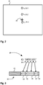
- the system 1 comprises a remote control device 3 and a plurality of user devices 25-1, 25-2 and 25-3.
- the remote control device 3 comprises a directional optical sensor 5.
- the directional optical sensor 5 may for example be a camera that provides images to the processor 6 for further analysis thereof.
- the remote control 3 also comprises a plurality of control modules 12, which may be hardware control modules or software coded modules. Alternatively, the control modules may be external control modules.
- a memory or data storage unit 7 and a wireless data communication unit 10 may be comprised by the remote control device 3.
- the data communication unit 10 may apply any suitable data communication protocol suitable for controlling user devices, e.g. a radio interface or optical transmission.
- remote control device 3 there may be a (standard or touch sensitive) display screen 15, for providing information to a user and/or receive input from the user.
- the remote control device 3 may also comprise a keyboard comprising a number of input keys, such as knob 16 for receiving input from the user.
- input may also be obtained via gesture detection e.g. based on camera data or motion sensor data, e.g. received from a motion sensor (not shown) like for instance an accelerometer (not shown).
- Each of the user devices 25-1, 25-2, and 25-3 at least comprises a number of elements that enable to provide the remote control device 3 with the device identifier, and to receive or exchange control data such as control commands from the remote control device 3.
- corresponding elements of each user device 25-1 to 25-3 is indicated with a similar reference numeral comprising a prefix-1, -2, or -3 such as to refer to the respective corresponding user devices 25-1, 25-2, 25-3.
- the elements of user device 25-1 will be described in more details, but this description likewise applies to the corresponding elements of user device 25-2 and that of user device 25-3.
- User device 25-1 comprises a controller 28-1.
- the user device 25-1 may have a memory (not shown), e.g. including therein a stored device identified, although this is not required.
- An identifier may be made available in device 25-1 in a different manner, e.g. by means of a hardware configurable solution (not shown) such as a set of jumper elements or dip switches.
- the device 25-1 further comprises an optical transmitter 26-1 which is arranged for providing an optical signal that may be received by remote control device 3.
- the optical signal provided by optical transmitter 26-1 may for example be an infrared optical signal, although this is not required per se (an optical signal of any other wavelength may also be applied).
- the optical signal transmitted by optical transmittal 26-1 is an intensity modulated optical signal which is generated using a modulator 30-1 under the control of controller 28-1.
- the controller 28-1 encodes a binary identifier of user device 25-1 into a plurality of signal fragments, including a header and/or trailer fragment at the beginning or end of the sequence.
- a header and a trailer may be included in the optical signal, this is not required in all implementations.
- either the header or the trailer may be absent, and even both the header and trailer may be absent in embodiments wherein the first and last signal fragments may be otherwise recognized.
- the signal fragments assembled are used by the controller 28-1 for controlling the modulator 30-1 such as to modulate the optical signal transmitted by optical transmitter 26-1 to be composed of the signal fragments assembled.
- the manner of coding the identifier of user device 25-1 into the various signal fragments will be explained later.
- User devices 25-2 and 25-3 operate in a similar manner.
- the identifiers may be preprogrammed in a memory or other element of the devices 25-1, 25-2, or 25-3.
- identifiers are provided by or managed using a server. This server could be external to the remote control device 3 and to the other devices 25-1 to 25-3, or could be integrated with any of the devices (3, 25-1, 25-2, 25-3) present in the system.
- Fig.1 an optional server or management unit 21 is shown that interfaces both device 3 and devices 25, such as to keep the design of device 3 simple.
- This server or management unit 21 can be responsible for handing out (local network unique) identifiers like an internet address. Identifiers might also be hardcoded at the media access layer or data link layer (OSI model) and unique like or being a MAC address in most IEEE 802 network technologies like Ethernet, 802.11 wireless networks, Bluetooth, etc.. Another identifier assignment could be based on pairing techniques where a control device is brought in close contact to the beacon after which the control device recognizes the beacon and assigns an identification code.
- OSI model media access layer or data link layer
- Another identifier assignment could be based on pairing techniques where a control device is brought in close contact to the beacon after which the control device recognizes the beacon and assigns an identification code.
- each device 25-1, 25-2 and 25-3 comprises an optical transmitter 26-1, 26-2 and 26-3 that is operable as a beacon for optical communication with the remote control device 3.
- the beacons 26-1, 26-2 and 26-3 are arranged for transmitting an optical modulated signal at infrared wavelength.
- the optical signal is preferably omnidirectional, i.e. transmitted in many directions and not particularly focused in a specific direction, such that it can be received in a large part of the room wherein the devices 25-1 to 25-3 are located.
- the beacons 26-1 to 26-3 send out an optical signal comprising a code containing their device identification information.
- the devices 25-1 to 25-3 may be arranged for sending out the code continuously while switched on, or may be arranged for sending out the code in response to any event or trigger signal.
- a general trigger may be transmitted by the remote control device 3 when it is picked up by a user, e.g. in response to a signal from an acceleration sensor (not shown) comprised by the remote control device 3.
- a user may operate knob 16 on the remote control device 3 to send a general trigger signal.
- the user points with the remote device 3 in the direction of the device 25-1 that he wants to select.
- the camera 5 in the remote control device 3 captures an image that could look the image illustrated in figure 2 .
- the optical sensor 5 has a large view angle, a number of beacons 26-1, 26-2 and 26-3 will be visible in the image as illustrated in figure 2 .
- the sensor image 35 is a mirrored projection of the environment imaged (point-symmetric vis-à-vis the center 36 of the image, with top becoming bottom, and left becoming right). Devices that are seen by the camera under different angles with respect to the central axis will be presented at different locations on the image 35.
- the devices 25-1, 25-2 and 25-3 are located on top of each other, as illustrated in figure 1 .
- the optical transmitter or beacon 26-1 at which the user is pointing at with remote control device 3 will be closest to the image sensor center 36 as indicated in figure 2 .
- the processor 6 of the remote control device 3 may select device 25-1 as being the device to be controlled, and starts keeping track of the signal transmitted by optical transmitter 26-1.
- other selection criteria may be used for selecting the device to be controlled.
- this selection does not have to take place immediately upon receipt of one or more optical signals, but could take place simultaneous with other steps of the identification process or all at the end.
- Figure 3 illustrates, as an example, an encoding method in accordance with the present invention such as to encode an identifier of one of the user devices (25-1, 25-2, 25-3) into an optical signal for transmission.
- the user holding the remote control device 3 may usually not be able to hold the remote control device 3 completely still. Therefore, in case the user intends to control user device 25-1, as a result of motion of the hands of the user the optical signal corresponding with optical transmitter 26-1 (e.g. as illustrated in figure 2 ) will be moving in the image 35 during analysis.
- the processor 6 of the remote control device 3 will keep track of the optical signal in the image received.
- the processor may no longer be able to keep track of the signal of optical transmitter 26-1 in the image 35.
- the optical signal may get lost.
- the signal-to-noise ratio (SNR) during the low signal states will still be considerably low in comparison with the SNR during the high signal state.
- the processor 6 may still not be able to keep track of the optical signal.
- the alternative identification method wherein the beacon is always in an on-state, but modulated with a sine wave or other code at low modulation index will suffer from a deteriorated SNR already, in particular due to the insensitive pixel boundaries of the optical sensor 5. For example, when a blob moves over the image sensor pixels, the blob brightness signal will vary when part of the blob passes the insensitive part between the pixels. Large amplitude noise will be introduced. As a results SNR becomes so bad that signal detection cannot be done reliable anymore.
- a code may be used with maximum number of 1's and minimal number of 0's.
- the present invention applies a coding method wherein the duration of the high signal states is much longer than the duration of the low signal states. Preferably, the duration of the low signal states is minimized in comparison to the duration of the high signal states.
- the low signal states have fixed and minimal durations and serve primarily as delimiters of the high signal states.
- the low signal states enable the processor 6 to recognize the high signal states and to measure their duration in time.
- the information to be conveyed in this embodiment is encoded in the duration of the high signal states.
- the optical signal comprises a plurality of signal fragments 42, 43, 45, 46, 47 and 50.
- Signal fragment 42 is the header fragment that precedes the payload signal fragments.
- Signal fragment 50 is a trailer signal fragment indicating the end of the optical signal 40.
- Identifier 38 consists of 8 bits: 1001101 (decimal: 141). The 8 bits of identifier 38 are separated by controller 28-1 of the user device 25-1 into bit pairs, such as bit pair 39. Each bit pair comprises two bits of the 8 bit identifier. As may be appreciated, in different implementations it is also possible to encode single bits or triplets of bits or a different number of bits; the number of bits encoded in each signal fragment may be chosen by the skilled person.
- Each bit pair such as bit pair 39, is encoded in a respective payload signal fragment 44, 45, 46, and 47.
- the bit pairs are encoded such that their information is conveyed in the duration of the high signal state of the optical signal 40. Therefore, the various possible bit configurations of each bit pair may be encoded such as indicated in table 1 below.
- Table 1 Signal fragment type Channel symbol Header 011111 Payload_00 01 Payload_01 011 Payload_10 0111 Payload_11 01111 Trailer 0
- bit pair 39 consisting of '10' is encoded into signal fragments '0111'.
- the other bit pairs are encoded such as is indicated in figure 3 in signal fragments 45, 46, and 47.
- the optical signal is preceded by the header signal fragment 42 and terminated by the trailer signal fragment 50. All this may be performed by the controller 28-1 of user device 25-1. Then, the controller operates the modulator 30-1 for modulating the optical signal transmitted by optical transmitter 26-1.
- FIG 4 schematically illustrates a method of operating a remote control device 3 in accordance with the principles of the present invention.
- the method starts in step 54 by the remote control device 3 providing a trigger signal e.g. via the data communication unit 10 to all devices in the environment.
- step 54 is an optional step of an implementation wherein a trigger signal is used for triggering the user devices 25-1 to 25-3 to start transmitting an optical identifier signal.
- the optical identifier signals may for example continuously be sent in a repeating manner by the devices 25-1 to 25-3 and in that case, the remote control simply starts receiving the optical identifier signals in step 55 when the remote control device is pointed at the devices 25-1 to 25-3.
- the optical identifier signal is repeated a predetermined number of times (e.g. 1x, 2x, 3x, 4x, 5x, 6x, ...) after receipt of a trigger by the devices 25-1 to 25-3 provided by remote control device 3.
- the remote control device is in sleep mode, and some internal trigger (e.g. the generated due to user operation of the remote control device 3) is required to wake-up the remote control device 3 to start receiving the optical signals in step 55.
- some internal trigger e.g. the generated due to user operation of the remote control device 3
- the optical signals transmitted by one or more user devices 25-1 to 25-3 are received in step 55 of the method in figure 4 .
- step 56 it is determined by the processor whether the image contains only a single optical signal or whether multiple optical signals are present in the image received from the directional optical sensor 5. In case multiple optical signals are present in the image 35 received from optical sensor 5, a method continues in step 59 wherein at least one of the received optical signals is selected as the candidate optical signal for the user device to be controlled. As may be appreciated, dependent on the implementation also more than one received optical signal may be selected as a candidate signal. Moreover, the step of selection of the candidate signal may be performed either at the beginning of the method (as illustrated in figure 4 ) or during any of the subsequent steps, or even all at the end of the method.
- Method step 60 and the sequence of steps 64 through 76 are then performed simultaneously, i.e. method step 60 resembles the processor 6 keeping track of the at least one optical signal selected in step 59, and the processor must keep track of this signal for as long as the optical signal is being received and analyzed.
- the processor 6 While the processor 6 keeps track of the at least one optical signal, the processor also starts analyzing the at least one optical signal in steps 64 through 76.
- step 64 the processor 6 recognizes the signal fragments that are present in the optical signal, e.g. by recognizing the locations of the low signal states in the optical signal considered.
- step 66 the signal fragment being received is read by the processor, starting with the first signal fragment.
- step 68 the processor determines whether a received signal fragment is a header type signal fragment. If the signal fragment is a header type signal fragment, the processor in step 69 waits for the next fragment and returns to step 66. In case the signal fragment read in step 66 is not a header type signal fragment, then in step 72 the processor determines whether the received signal fragment is a trailer type signal fragment.
- step 73 the processor establishes that the signal fragment is a payload type signal fragment, and decodes the signal fragment value represented.
- the signal fragment value is stored in memory 7 for later use.
- step 69 wait for the next signal fragment.
- step 72 the processor determines that a received signal fragment is a trailer type signal fragment
- step 75 the processor 6 retrieves the decoded and stored signal fragment values from the memory 7 and composes the identifier represented by the optical signal from these signal fragment values.
- step 76 using the received identifier of the user device 25-1 the processor 6 identifies the user device 25-1, establishing which device this is.
- the identification method then ends, and may of course be followed (as usually will be the case) by the user controlling the user device 25-1.
- codes can be transmitted back-to-back, and a receiver can start decoding on the fly at any moment in time (so even halfway transmission code).
- an average delay of 50% of transmission length may be introduced (maximum 100%).
- the proposed receiver starts decoding immediate, and saves average 50% transmission length detection time (maximum 100%). The receiver will be able to detect any complete fragment of back-to-back repeated code words.
- Next steps may for example be the selection of the correct control module 12 by the remote control device for controlling the identified user device 25-1.
- various control modules may be present in the remote control device, either in hardware or software coded, and may be applied by the remote control device for controlling device 25-1.
- the remote control device upon identifying the type of device 25-1, retrieves the correct control module and may be a relevant user interface, from an external source. This might be the server or management unit 21. It can receive such information from server 21 direct or indirect, i.e. server 21 might be part and hence connected to a larger network (and even intranet or internet).
- the remote control device may retrieve the control module or user interface from the device 25-1 itself, or it may be retrieved from a remote server. Then, upon receiving input from the user, the remote control device sends control commands to the user device 25-1 by means of the data communication unit 10, and the corresponding data communication unit 32-1 of user device 25-1.
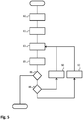
- step 80 a method of composing an optical signal for identification of a user device, such as may be applied in user device 25-1, is schematically illustrated.
- the method of figure 5 starts in step 80, where the user device identifier of user device 25-1 is separated into bit pairs. From the separated bit pairs, in step 81 the controller 28-1 of the user device 25-1 composes the signal fragments, preceded by a header type signal fragment and terminated by a trailer type signal fragment. In step 83, the controller 28-1 selects the fragments to be sent (e.g. header first, second, third...etc.). Then in step 85, the controller operates the modulator 30-1 in accordance with the bits of which the signal fragments considered is composed.
- the modulator applies a high signal state when it receives a '1' from the controller 28-1, and it applies a low signal state when it receives a '0' from the controller 28-1.
- the optical signal is transmitted by the optical transmitter 26-1, which is connected to the modulator and receives the high and low signal states.
- the controller 28-1 may verify whether the method can be stopped. For example, this may be in response to receiving a interrupt signal, or in response to any other event taking place within user device 25-1. Usually, the optical signal will be retransmitted from start after the last signal fragment (the trailer signal fragment) has been transmitted. A guarding interval is not desired in order to maintain tracking. Alternatively, at some point the controller 28-1 may decide that transmission is no longer necessary, and may stop the transmission in step 86. In other embodiments, the user devices 25-1 may be arranged for continuously transmitting the optical signal without stopping. In case the method does not have to be stopped in step 86, it continues in step 88 wherein the controller 28-1 determines whether the transmitted signal fragment was a trailer signal fragment.
- step 90 transmission is restarted from the first signal fragment of the optical signal.
- Step 90 is thus a restart step, and the method continues again in step 83 (selection of the signal fragment to be sent).
- step 92 indicating to the controller that the next signal fragment is to be selected for transmission. Thereafter, the method again continues in step 83.
- the device 25-1 or the remote control 3 may provide user feedback. For example, on the device a LED signal or other indicator (e.g. visible or audible) may be provided after selection or after becoming selection candidate.
- optical signal blob
- all blob positions and identification information may be in the memory 7 of the remote control 3.
- this data may be obtained by the remote control device 7 from the server 21.
- Selection of optical identifier signals could be based on a relation between their positions or identification codes. Possibilities are for example the selection of a group of devices (each device equipped with single beacon) or detection of an orientation of a device relative to the remote control and/or a room.
- device 25-1 can be equipped with number of beacons that for example transmit the same device identifier for allowing the remote control device 3 to recognize and select all corresponding signals. From the image, if the remote control device 3 is aware of the positions of each optical transmitter on the device 25-1, the orientation may be calculated (with or without aid from the server 21).
Landscapes
- Engineering & Computer Science (AREA)
- Physics & Mathematics (AREA)
- General Physics & Mathematics (AREA)
- Computer Networks & Wireless Communication (AREA)
- General Engineering & Computer Science (AREA)
- Theoretical Computer Science (AREA)
- Human Computer Interaction (AREA)
- Selective Calling Equipment (AREA)
- Optical Communication System (AREA)
- Arrangements For Transmission Of Measured Signals (AREA)
- Details Of Television Systems (AREA)
Claims (14)
- Fernsteuervorrichtung (3) zum Steuern einer oder mehrerer Benutzervorrichtungen (25-1, 25-2, 25-3), umfassend: eine Eingabeeinrichtung (16) zum Empfangen einer Eingabe von einem Benutzer und einen Sender (10) zum Senden von Steuerbefehlen an die eine oder die mehreren Benutzervorrichtungen um diese zu steuern, ferner einen direktionalen optischen Sensor (5) zum Empfangen eines oder mehrerer optischer Signale von den Benutzervorrichtungen und zum Erfassen einer Ankunftsrichtung der empfangenen optischen Signale und einen Prozessor (6),
wobei der Prozessor dafür eingerichtet ist, zur Erkennung von mindestens einer der Benutzervorrichtungen mindestens eines von den empfangenen optischen Signalen zu analysieren, um dieses der mindestens einen Benutzervorrichtung zuzuordnen.
wobei das eine oder die mehreren optischen Signale High- und Low-Signalzustände aufweisen, und wobei jedes optische Signal aus einem oder mehreren Signalfragmenten besteht, wobei jedes Signalfragment einen ansteigenden oder abfallenden Low-Signalzustand und einen High-Signalzustand umfasst,
dadurch gekennzeichnet, dass eine Dauer des High-Signalzustands jedes Signalfragments einen Signalfragmenttyp des Signalfragments bestimmt, und wobei die Dauer des High-Signalzustands länger ist als eine Dauer des Low-Signalzustands, und
dadurch, dass der Prozessor dafür eingerichtet ist, bei einer Änderung der Ankunftsrichtung das mindestens eine von den optischen Signalen weiter zu verfolgen und das Zuordnen des mindestens einen empfangenen optischen Signals zu der mindestens einen von den Benutzervorrichtungen durchzuführen durch:- Erkennen des einen oder der mehreren Signalfragmente und Zuordnen jedes Signalfragments zu seinem Signalfragmenttyp, um daraus ein Signalmuster zu erhalten, das eindeutig der mindestens einen von den Benutzervorrichtungen zuzuordnen ist,- Decodieren eines Signalfragmentwerts, der in dem einen oder in jedem von den mehreren Signalfragmenten dargestellt wird, die zum Nutzlastdatentyp gehören, und- Kombinieren der Signalfragmentwerte, um eine binäre Kennung zu erhalten, die der mindestens einen von den Benutzervorrichtungen zugeordnet ist. - Fernsteuervorrichtung nach Anspruch 1, wobei die ansteigenden oder abfallenden Low-Signalzustände der Signalfragmente von einer festen Dauer sind, die in Bezug auf die Dauer des High-Signalzustands minimiert ist, und wobei der Prozessor dafür ausgelegt ist, die Low-Signalzustände zu erfassen, um das eine oder die mehreren Signalfragmente innerhalb des mindestens einen empfangenen optischen Signals unterscheiden zu können.
- Fernsteuervorrichtung nach einem der vorangehenden Ansprüche, wobei die empfangenen optischen Signale binäre Signale darstellen, die aus Bitfolgen gebildet sind, wobei für jedes Signalfragment die High-Signalzustände aus einem oder mehreren High-Bits gebildet sind und die Low-Signalzustände aus mindestens einem Low-Bit gebildet sind, wobei der Prozessor dafür ausgelegt, die Zahl aufeinanderfolgender High-Bits aus jedem Signalfragment zu bestimmen und den Signalfragmenttyp aus der Zahl der High-Bits zu bestimmen.
- Fernsteuervorrichtung nach einem der vorangehenden Ansprüche, wobei der Prozessor dafür ausgelegt ist, das mindestens eine von den empfangenen optischen Signalen zur Analyse desselben auszuwählen, wobei die Auswahl von einer erfassten Ankunftsrichtung der empfangenen optischen Signale abhängt.
- Fernsteuervorrichtung nach einem der vorangehenden Ansprüche, wobei der direktionale optische Sensor mindestens ein Element einer Gruppe umfasst, die umfasst: eine Kamera zur Bereitstellung von Bildern am Prozessor für die Durchführung der Analyse, eine Anordnung von p-i-n-Photodioden.
- Benutzervorrichtung (25-1, 25-2, 25-3), die dafür eingerichtet ist, mittels einer Fernsteuervorrichtung (3) nach einem der vorangehenden Ansprüche betrieben zu werden, wobei die Benutzervorrichtung umfasst:einen Empfänger (32-1, 32-2, 32-3) zum Empfangen von Steuerbefehlen von der Fernsteuervorrichtung zum Steuern der Benutzervorrichtung,einen optischen Sender (26-1, 26-2, 26-3) zum Senden eines optischen Signals undeinen Modulator (30-1, 30-2, 30-3), der mit dem optischen Sender zusammenwirkt, um das optische Signal so zu modulieren, dass es High- und Low-Signalzustände aufweist, und so, dass jedes optische Signal aus einer Vielzahl von Signalfragmenten besteht, wobei jedes Signalfragment einen ansteigenden und einen abfallenden Low-Signalzustand und einen High-Signalzustand aufweist.dadurch gekennzeichnet, dass eine Dauer des High-Signalzustands jedes Signalfragments einen Signalfragmenttyp des Signalfragments bestimmt, und wobei die Dauer des High-Signalzustands länger ist als eine Dauer des Low-Signalzustands, unddadurch, dass die Benutzervorrichtung ferner umfasst: einen Controller (28-1, 28-2, 28-3), der dafür ausgelegt ist, eine binäre Kennung, die der Benutzervorrichtung zugeordnet ist, als Vielzahl von Nutzlastsignalfragmenten der Vielzahl von Signalfragmenten zu kodieren und mit dem Modulator zusammenzuwirken, um eine Modulation des optischen Signals entsprechend einem Signalmuster, das von der Vielzahl von Signalfragmenten gemeinsam gebildet wird und das aus Signalfragmenten einer Kombination von Signalfragmenttypen besteht, zu ermöglichen.
- Benutzervorrichtung nach Anspruch 6, wobei die ansteigenden oder abfallenden Low-Signalzustände der Signalfragmente eine feste Dauer haben, die in Bezug auf die Dauer des High-Signalzustands minimiert ist.
- Benutzervorrichtung nach Anspruch 6 oder 7, wobei der Modulator dafür eingerichtet ist, die optischen Signale so zu modulieren, dass sie binäre Signale darstellen, die aus Bitsequenzen gebildet sind, wobei für jedes Signalfragment die High-Signalzustände aus einem oder mehreren High-Bits gebildet sind und die Low-Signalzustände aus mindestens einem Low-Bit gebildet sind, wobei der Controller ferner dafür ausgelegt ist, folgen aus einem oder mehreren Bits, die eine Kennung darstellen, in Signalfragmente umzuwandeln, die aus mindestens einem Low-Bit und einer Vielzahl von High-Bits bestehen, wobei die Zahl der High-Bits einen Signalfragmenttyp darstellt.
- Benutzervorrichtung nach einem oder mehreren der Ansprüche 6-8, wobei die Benutzervorrichtung eine Vielzahl von optischen Sendern zum Senden des optischen Signals umfasst, um die Fernsteuervorrichtung in die Lage zu versetzen, eine räumliche Orientierung oder einen Standort der Benutzervorrichtung festzustellen.
- Benutzervorrichtung nach einem oder mehreren der Ansprüche 6-9, wobei der Controller dafür ausgelegt ist, die binäre Kennung in Gruppen von zwei oder mehr Bits zu trennen und jede von den Gruppen in ein entsprechendes Nutzlastsignalfragment der Vielzahl zu kodieren.
- System (1), mindestens eine Fernsteuervorrichtung (3) nach einem oder mehreren der Ansprüche 1-5 und mindestens eine Benutzervorrichtung (25-1, 25-2, 25-3) nach einem oder mehreren der Ansprüche 6-10 umfassend.
- Verfahren zum Betreiben einer Fernsteuervorrichtung (3) zum Steuern einer oder mehrerer Benutzervorrichtungen (25-1, 25-2, 25-3), wobei das Verfahren die folgenden Schritte umfasst:Empfangen eines oder mehrerer optischer Signale von den Benutzervorrichtungen und Erfassen einer Ankunftsrichtung der empfangenen optischen Signale unter Verwendung eines optischen Sensors (5);Identifizieren mindestens einer der Benutzervorrichtungen durch Analysieren mindestens eines von den empfangenen optischen Signalen durch einen Prozessor (6), um es der mindestens einen Benutzervorrichtung zuzuordnen;wobei zur Durchführung des Identifizierungsschrittes das eine oder die mehreren optischen Signale High- und Low-Signalzustände aufweisen, und wobei jedes optische Signal aus einem oder mehreren Signalfragmenten besteht, wobei jedes Signalfragment einen ansteigenden oder abfallenden Low-Signalzustand und einen High-Signalzustand umfasst,dadurch gekennzeichnet, dass der Identifizierungsschritt ferner den Schritt des Weiterverfolgens des mindestens einen von den optischen Signalen bei einer Änderung der Ankunftsrichtung unter Verwendung des Prozessors umfasst, wobei eine Dauer des High-Signalzustands jedes Signalfragments einen Signalfragmenttyp des Signalfragments bestimmt, und wobei die Dauer des High-Signalzustands länger ist als eine Dauer des Low-Signalzustands; unddadurch, dass der Schritt des Zuordnens des mindestens einen optischen Signals zu der mindestens einen von den Benutzervorrichtungen von dem Prozessor durch die folgenden Schritte durchgeführt wird:- Erkennen des einen oder der mehreren Signalfragmente und Zuordnen jedes Signalfragments zu seinem Signalfragmenttyp, um daraus ein Signalmuster zu erhalten, das eindeutig der mindestens einen von den Benutzervorrichtungen zuzuordnen ist,- Decodieren eines Signalfragmentwerts, der in dem einen oder in jedem von den mehreren Signalfragmenten dargestellt wird, die zum Nutzlastdatentyp gehören, und- Kombinieren der Signalfragmentwerte, um eine binäre Kennung zu erhalten, die der mindestens einen von den Benutzervorrichtungen zugeordnet ist.
- Verfahren zum Kombinieren eines optischen Signals zur Identifizierung in einer Benutzervorrichtung (25-1, 25-2, 25-3), die einen optischen Sender (26-1, 26-2, 26-3) umfasst, wobei die Benutzervorrichtung dafür ausgelegt ist, mittels einer Fernsteuervorrichtung (3) nach einem der Ansprüche 1-5 betrieben zu werden, wobei das Verfahren umfasst:Kodieren einer binären Kennung, die der Benutzervorrichtung zugeordnet ist, als Vielzahl von Nutzlastsignalfragmente unter Verwendung eines Controllers (28-1, 28-2, 28-3),Modulieren eines optischen Signals unter Verwendung eines Modulators (30-1, 30-2, 30-3), der mit dem optischen Sender zusammenwirkt, so dass es High- und Low-Signalzustände aufweist und so, dass jedes optische Signal aus einer Vielzahl von Signalfragmenten besteht, wobei jedes Signalfragment einen ansteigenden oder abfallenden Low-Signalzustand und einen High-Signalzustand aufweist, wobei eine Dauer des High-Signalzustands jedes Signalfragments einen Signalfragmenttyp des Signalfragments bestimmt und wobei die Dauer des High-Signalzustands länger ist als eine Dauer des Low-Signalzustands, wobei die Vielzahl von Signalfragmenten die Vielzahl von Nutzlastsignalfragmenten einschließt;Ermöglichen einer Modulation des optischen Signals unter Verwendung des Controllers, der mit dem Modulator zusammenwirkt, gemäß einem Signalmuster, das von der Vielzahl von Signalfragmenten gemeinsam gebildet wird und das aus Signalfragmenten einer Kombination von Signalfragmenttypen besteht; undSenden des optischen Signals mittels des optischen Senders.
- Nicht-flüchtiges Medium, ein Computerprogrammprodukt umfassend, das Befehle umfasst, die bei ihrer Ausführung durch eine Fernsteuervorrichtung (3), die einen direktionalen optischen Sensor (5) und einen Prozessor (6) umfasst, bewirkt, dass die Fernsteuervorrichtung das Verfahren nach Anspruch 12 durchführt.
Applications Claiming Priority (2)
| Application Number | Priority Date | Filing Date | Title |
|---|---|---|---|
| EP14186731 | 2014-09-29 | ||
| PCT/EP2015/072287 WO2016050708A1 (en) | 2014-09-29 | 2015-09-28 | Remote control device, user device and system thereof, and method, computer program product and identification signal |
Publications (2)
| Publication Number | Publication Date |
|---|---|
| EP3201893A1 EP3201893A1 (de) | 2017-08-09 |
| EP3201893B1 true EP3201893B1 (de) | 2020-12-23 |
Family
ID=51625905
Family Applications (1)
| Application Number | Title | Priority Date | Filing Date |
|---|---|---|---|
| EP15770890.0A Active EP3201893B1 (de) | 2014-09-29 | 2015-09-28 | Fernsteuerungsvorrichtung, benutzergerät und system dafür sowie verfahren, computerprogrammprodukt |
Country Status (5)
| Country | Link |
|---|---|
| US (1) | US10289213B2 (de) |
| EP (1) | EP3201893B1 (de) |
| JP (1) | JP6612853B2 (de) |
| CN (1) | CN106716511B (de) |
| WO (1) | WO2016050708A1 (de) |
Families Citing this family (4)
| Publication number | Priority date | Publication date | Assignee | Title |
|---|---|---|---|---|
| KR102500072B1 (ko) * | 2016-08-04 | 2023-02-16 | 삼성전자주식회사 | 원격 제어 장치 및 그 제어 방법 |
| US11158187B2 (en) * | 2016-11-21 | 2021-10-26 | Koninklijke Philips N.V. | Remote-control device and user device using an identification signal |
| GB201719106D0 (en) * | 2017-11-17 | 2018-01-03 | Magic Of Things Ltd | A wand-configured user control device for contorlling devices in a user environment |
| TWI739370B (zh) * | 2020-04-01 | 2021-09-11 | 瑞昱半導體股份有限公司 | 訊號處理裝置及訊號處理方法 |
Family Cites Families (19)
| Publication number | Priority date | Publication date | Assignee | Title |
|---|---|---|---|---|
| US6655817B2 (en) | 2001-12-10 | 2003-12-02 | Tom Devlin | Remote controlled lighting apparatus and method |
| US7224903B2 (en) * | 2001-12-28 | 2007-05-29 | Koninklijke Philips Electronics N. V. | Universal remote control unit with automatic appliance identification and programming |
| US6990639B2 (en) | 2002-02-07 | 2006-01-24 | Microsoft Corporation | System and process for controlling electronic components in a ubiquitous computing environment using multimodal integration |
| JP4207490B2 (ja) * | 2002-08-06 | 2009-01-14 | ソニー株式会社 | 光通信装置、光通信データ出力方法、および光通信データ解析方法、並びにコンピュータ・プログラム |
| DE60331271D1 (de) * | 2002-10-24 | 2010-03-25 | Nakagawa Lab Inc | Vorrichtung zur Beleuchtung und Datenübertragung |
| PT2093650E (pt) | 2002-11-20 | 2013-07-25 | Koninkl Philips Electronics Nv | Sistema de interface para utilizador com base num dispositivo apontador |
| CN1961507A (zh) * | 2004-05-28 | 2007-05-09 | 皇家飞利浦电子股份有限公司 | Uart编码的脉冲调制技术 |
| KR100710306B1 (ko) * | 2005-01-20 | 2007-04-23 | 엘지전자 주식회사 | 코드 포맷 구조를 갖는 리모콘과 그의 송수신 방법 및 장치 |
| WO2006079939A2 (en) * | 2005-01-28 | 2006-08-03 | Philips Intellectual Property & Standards Gmbh | Method for control of a device |
| JP4148248B2 (ja) * | 2005-07-14 | 2008-09-10 | 船井電機株式会社 | リモコン装置および遠隔制御システム |
| US8027359B2 (en) * | 2007-03-26 | 2011-09-27 | Sony Corporation | Extended serial communication protocols |
| TWI353736B (en) | 2007-11-23 | 2011-12-01 | Compal Communications Inc | Device of wireless remote control and operating me |
| US8477010B2 (en) * | 2008-01-25 | 2013-07-02 | Somfy Sas | Method for communicating information by infrared rays between a transmitter and a receiver in a home-automation network |
| BRPI0909988A2 (pt) * | 2008-06-11 | 2019-09-24 | Koninl Philips Electronics Nv | sistema de seleção de dispositivo de controle remoto sem fio, dispositivo de controle remoto, primeiro dispositivo que compreende uma lâmpada e método para selecionar pelo menos um dentre um primeiro dispositivo e um segundo dispositivo |
| US20120025949A1 (en) * | 2010-07-29 | 2012-02-02 | Reed Matthew H | Concurrent Infrared Signal, Single Thread Low Power Protocol and System for Pet Control |
| CN102216918B (zh) * | 2011-05-30 | 2014-04-16 | 华为终端有限公司 | 设备标识信息的获取方法及装置 |
| US9208680B2 (en) * | 2012-01-12 | 2015-12-08 | Lumen Radio Ab | Remote commissioning of an array of networked devices |
| WO2014061257A1 (ja) * | 2012-10-15 | 2014-04-24 | パナソニック株式会社 | 認識装置、認識方法、遠隔制御装置、認識プログラム、及びサーバ |
| CN103914969A (zh) | 2013-01-07 | 2014-07-09 | 凹凸电子(武汉)有限公司 | 移动终端装置以及控制电器设备的方法 |
-
2015
- 2015-09-28 US US15/506,282 patent/US10289213B2/en active Active
- 2015-09-28 CN CN201580052807.2A patent/CN106716511B/zh active Active
- 2015-09-28 EP EP15770890.0A patent/EP3201893B1/de active Active
- 2015-09-28 JP JP2017512944A patent/JP6612853B2/ja active Active
- 2015-09-28 WO PCT/EP2015/072287 patent/WO2016050708A1/en not_active Ceased
Non-Patent Citations (1)
| Title |
|---|
| None * |
Also Published As
| Publication number | Publication date |
|---|---|
| JP6612853B2 (ja) | 2019-11-27 |
| CN106716511B (zh) | 2020-04-14 |
| JP2017537485A (ja) | 2017-12-14 |
| WO2016050708A1 (en) | 2016-04-07 |
| EP3201893A1 (de) | 2017-08-09 |
| US20180217677A1 (en) | 2018-08-02 |
| CN106716511A (zh) | 2017-05-24 |
| US10289213B2 (en) | 2019-05-14 |
Similar Documents
| Publication | Publication Date | Title |
|---|---|---|
| US9723698B2 (en) | Remote control method and system for lighting apparatus | |
| CN112198819B (zh) | 负载控制系统及设备 | |
| EP3201893B1 (de) | Fernsteuerungsvorrichtung, benutzergerät und system dafür sowie verfahren, computerprogrammprodukt | |
| US20120299709A1 (en) | Remote control device, remote control system, and storage medium storing control program, and medium to be attached to electrical device | |
| EP2575105B1 (de) | Informationserfassungsvorrichtung, Informationsverfassungsverfahren, Programm und Informationserfassungssystem | |
| US9378639B2 (en) | Target identification for sending content from a mobile device | |
| US20150028746A1 (en) | Augmented reality graphical user interface for network controlled lighting systems | |
| KR20150101140A (ko) | 지그비 무선 조명 제어 방법 및 그 장치 | |
| US20150200788A1 (en) | Automated device identification | |
| EP3186795B1 (de) | Ferngesteuerte vorrichtung und fernsteuerung zur steuerung mehrerer ferngesteuerter vorrichtungen | |
| US10659157B2 (en) | Apparatus and method for registering visible light communication device and combining visible light communication signal and wireless communication signal | |
| JP2009296239A (ja) | 情報処理システムおよび情報処理方法 | |
| US10564985B2 (en) | Boot system and boot method for intelligent robot | |
| US11158187B2 (en) | Remote-control device and user device using an identification signal | |
| JP2004178469A (ja) | 遠隔制御システム | |
| EP2688229B1 (de) | Verfahren zur Detektion interaktiver Vorrichtungen und zugehörige Einrichtungen | |
| US10278266B1 (en) | Light modulated network password key delivery | |
| EP3435559B1 (de) | Drahtlose elektronische vorrichtung, betriebsumgebung und verfahren | |
| WO2024062617A1 (ja) | 光通信システム | |
| JP2014120889A (ja) | 端末装置、及び電子機器 |
Legal Events
| Date | Code | Title | Description |
|---|---|---|---|
| STAA | Information on the status of an ep patent application or granted ep patent |
Free format text: STATUS: THE INTERNATIONAL PUBLICATION HAS BEEN MADE |
|
| PUAI | Public reference made under article 153(3) epc to a published international application that has entered the european phase |
Free format text: ORIGINAL CODE: 0009012 |
|
| STAA | Information on the status of an ep patent application or granted ep patent |
Free format text: STATUS: REQUEST FOR EXAMINATION WAS MADE |
|
| 17P | Request for examination filed |
Effective date: 20170502 |
|
| AK | Designated contracting states |
Kind code of ref document: A1 Designated state(s): AL AT BE BG CH CY CZ DE DK EE ES FI FR GB GR HR HU IE IS IT LI LT LU LV MC MK MT NL NO PL PT RO RS SE SI SK SM TR |
|
| AX | Request for extension of the european patent |
Extension state: BA ME |
|
| DAV | Request for validation of the european patent (deleted) | ||
| DAX | Request for extension of the european patent (deleted) | ||
| STAA | Information on the status of an ep patent application or granted ep patent |
Free format text: STATUS: EXAMINATION IS IN PROGRESS |
|
| 17Q | First examination report despatched |
Effective date: 20190523 |
|
| RAP1 | Party data changed (applicant data changed or rights of an application transferred) |
Owner name: KONINKLIJKE PHILIPS N.V. |
|
| GRAP | Despatch of communication of intention to grant a patent |
Free format text: ORIGINAL CODE: EPIDOSNIGR1 |
|
| STAA | Information on the status of an ep patent application or granted ep patent |
Free format text: STATUS: GRANT OF PATENT IS INTENDED |
|
| INTG | Intention to grant announced |
Effective date: 20200708 |
|
| GRAS | Grant fee paid |
Free format text: ORIGINAL CODE: EPIDOSNIGR3 |
|
| GRAA | (expected) grant |
Free format text: ORIGINAL CODE: 0009210 |
|
| STAA | Information on the status of an ep patent application or granted ep patent |
Free format text: STATUS: THE PATENT HAS BEEN GRANTED |
|
| AK | Designated contracting states |
Kind code of ref document: B1 Designated state(s): AL AT BE BG CH CY CZ DE DK EE ES FI FR GB GR HR HU IE IS IT LI LT LU LV MC MK MT NL NO PL PT RO RS SE SI SK SM TR |
|
| REG | Reference to a national code |
Ref country code: GB Ref legal event code: FG4D |
|
| REG | Reference to a national code |
Ref country code: DE Ref legal event code: R096 Ref document number: 602015063849 Country of ref document: DE |
|
| REG | Reference to a national code |
Ref country code: AT Ref legal event code: REF Ref document number: 1348476 Country of ref document: AT Kind code of ref document: T Effective date: 20210115 |
|
| REG | Reference to a national code |
Ref country code: IE Ref legal event code: FG4D |
|
| PG25 | Lapsed in a contracting state [announced via postgrant information from national office to epo] |
Ref country code: GR Free format text: LAPSE BECAUSE OF FAILURE TO SUBMIT A TRANSLATION OF THE DESCRIPTION OR TO PAY THE FEE WITHIN THE PRESCRIBED TIME-LIMIT Effective date: 20210324 Ref country code: FI Free format text: LAPSE BECAUSE OF FAILURE TO SUBMIT A TRANSLATION OF THE DESCRIPTION OR TO PAY THE FEE WITHIN THE PRESCRIBED TIME-LIMIT Effective date: 20201223 Ref country code: RS Free format text: LAPSE BECAUSE OF FAILURE TO SUBMIT A TRANSLATION OF THE DESCRIPTION OR TO PAY THE FEE WITHIN THE PRESCRIBED TIME-LIMIT Effective date: 20201223 Ref country code: NO Free format text: LAPSE BECAUSE OF FAILURE TO SUBMIT A TRANSLATION OF THE DESCRIPTION OR TO PAY THE FEE WITHIN THE PRESCRIBED TIME-LIMIT Effective date: 20210323 |
|
| REG | Reference to a national code |
Ref country code: AT Ref legal event code: MK05 Ref document number: 1348476 Country of ref document: AT Kind code of ref document: T Effective date: 20201223 |
|
| REG | Reference to a national code |
Ref country code: NL Ref legal event code: MP Effective date: 20201223 |
|
| PG25 | Lapsed in a contracting state [announced via postgrant information from national office to epo] |
Ref country code: SE Free format text: LAPSE BECAUSE OF FAILURE TO SUBMIT A TRANSLATION OF THE DESCRIPTION OR TO PAY THE FEE WITHIN THE PRESCRIBED TIME-LIMIT Effective date: 20201223 Ref country code: LV Free format text: LAPSE BECAUSE OF FAILURE TO SUBMIT A TRANSLATION OF THE DESCRIPTION OR TO PAY THE FEE WITHIN THE PRESCRIBED TIME-LIMIT Effective date: 20201223 Ref country code: BG Free format text: LAPSE BECAUSE OF FAILURE TO SUBMIT A TRANSLATION OF THE DESCRIPTION OR TO PAY THE FEE WITHIN THE PRESCRIBED TIME-LIMIT Effective date: 20210323 |
|
| PG25 | Lapsed in a contracting state [announced via postgrant information from national office to epo] |
Ref country code: HR Free format text: LAPSE BECAUSE OF FAILURE TO SUBMIT A TRANSLATION OF THE DESCRIPTION OR TO PAY THE FEE WITHIN THE PRESCRIBED TIME-LIMIT Effective date: 20201223 Ref country code: NL Free format text: LAPSE BECAUSE OF FAILURE TO SUBMIT A TRANSLATION OF THE DESCRIPTION OR TO PAY THE FEE WITHIN THE PRESCRIBED TIME-LIMIT Effective date: 20201223 |
|
| REG | Reference to a national code |
Ref country code: LT Ref legal event code: MG9D |
|
| PG25 | Lapsed in a contracting state [announced via postgrant information from national office to epo] |
Ref country code: SK Free format text: LAPSE BECAUSE OF FAILURE TO SUBMIT A TRANSLATION OF THE DESCRIPTION OR TO PAY THE FEE WITHIN THE PRESCRIBED TIME-LIMIT Effective date: 20201223 Ref country code: PT Free format text: LAPSE BECAUSE OF FAILURE TO SUBMIT A TRANSLATION OF THE DESCRIPTION OR TO PAY THE FEE WITHIN THE PRESCRIBED TIME-LIMIT Effective date: 20210423 Ref country code: RO Free format text: LAPSE BECAUSE OF FAILURE TO SUBMIT A TRANSLATION OF THE DESCRIPTION OR TO PAY THE FEE WITHIN THE PRESCRIBED TIME-LIMIT Effective date: 20201223 Ref country code: LT Free format text: LAPSE BECAUSE OF FAILURE TO SUBMIT A TRANSLATION OF THE DESCRIPTION OR TO PAY THE FEE WITHIN THE PRESCRIBED TIME-LIMIT Effective date: 20201223 Ref country code: CZ Free format text: LAPSE BECAUSE OF FAILURE TO SUBMIT A TRANSLATION OF THE DESCRIPTION OR TO PAY THE FEE WITHIN THE PRESCRIBED TIME-LIMIT Effective date: 20201223 Ref country code: EE Free format text: LAPSE BECAUSE OF FAILURE TO SUBMIT A TRANSLATION OF THE DESCRIPTION OR TO PAY THE FEE WITHIN THE PRESCRIBED TIME-LIMIT Effective date: 20201223 Ref country code: SM Free format text: LAPSE BECAUSE OF FAILURE TO SUBMIT A TRANSLATION OF THE DESCRIPTION OR TO PAY THE FEE WITHIN THE PRESCRIBED TIME-LIMIT Effective date: 20201223 |
|
| PG25 | Lapsed in a contracting state [announced via postgrant information from national office to epo] |
Ref country code: PL Free format text: LAPSE BECAUSE OF FAILURE TO SUBMIT A TRANSLATION OF THE DESCRIPTION OR TO PAY THE FEE WITHIN THE PRESCRIBED TIME-LIMIT Effective date: 20201223 Ref country code: AT Free format text: LAPSE BECAUSE OF FAILURE TO SUBMIT A TRANSLATION OF THE DESCRIPTION OR TO PAY THE FEE WITHIN THE PRESCRIBED TIME-LIMIT Effective date: 20201223 |
|
| REG | Reference to a national code |
Ref country code: DE Ref legal event code: R097 Ref document number: 602015063849 Country of ref document: DE |
|
| PG25 | Lapsed in a contracting state [announced via postgrant information from national office to epo] |
Ref country code: IS Free format text: LAPSE BECAUSE OF FAILURE TO SUBMIT A TRANSLATION OF THE DESCRIPTION OR TO PAY THE FEE WITHIN THE PRESCRIBED TIME-LIMIT Effective date: 20210423 |
|
| PG25 | Lapsed in a contracting state [announced via postgrant information from national office to epo] |
Ref country code: AL Free format text: LAPSE BECAUSE OF FAILURE TO SUBMIT A TRANSLATION OF THE DESCRIPTION OR TO PAY THE FEE WITHIN THE PRESCRIBED TIME-LIMIT Effective date: 20201223 Ref country code: IT Free format text: LAPSE BECAUSE OF FAILURE TO SUBMIT A TRANSLATION OF THE DESCRIPTION OR TO PAY THE FEE WITHIN THE PRESCRIBED TIME-LIMIT Effective date: 20201223 |
|
| PLBE | No opposition filed within time limit |
Free format text: ORIGINAL CODE: 0009261 |
|
| STAA | Information on the status of an ep patent application or granted ep patent |
Free format text: STATUS: NO OPPOSITION FILED WITHIN TIME LIMIT |
|
| PG25 | Lapsed in a contracting state [announced via postgrant information from national office to epo] |
Ref country code: DK Free format text: LAPSE BECAUSE OF FAILURE TO SUBMIT A TRANSLATION OF THE DESCRIPTION OR TO PAY THE FEE WITHIN THE PRESCRIBED TIME-LIMIT Effective date: 20201223 |
|
| 26N | No opposition filed |
Effective date: 20210924 |
|
| PG25 | Lapsed in a contracting state [announced via postgrant information from national office to epo] |
Ref country code: ES Free format text: LAPSE BECAUSE OF FAILURE TO SUBMIT A TRANSLATION OF THE DESCRIPTION OR TO PAY THE FEE WITHIN THE PRESCRIBED TIME-LIMIT Effective date: 20201223 |
|
| PG25 | Lapsed in a contracting state [announced via postgrant information from national office to epo] |
Ref country code: SI Free format text: LAPSE BECAUSE OF FAILURE TO SUBMIT A TRANSLATION OF THE DESCRIPTION OR TO PAY THE FEE WITHIN THE PRESCRIBED TIME-LIMIT Effective date: 20201223 |
|
| REG | Reference to a national code |
Ref country code: CH Ref legal event code: PL |
|
| REG | Reference to a national code |
Ref country code: BE Ref legal event code: MM Effective date: 20210930 |
|
| PG25 | Lapsed in a contracting state [announced via postgrant information from national office to epo] |
Ref country code: IS Free format text: LAPSE BECAUSE OF FAILURE TO SUBMIT A TRANSLATION OF THE DESCRIPTION OR TO PAY THE FEE WITHIN THE PRESCRIBED TIME-LIMIT Effective date: 20210423 Ref country code: MC Free format text: LAPSE BECAUSE OF FAILURE TO SUBMIT A TRANSLATION OF THE DESCRIPTION OR TO PAY THE FEE WITHIN THE PRESCRIBED TIME-LIMIT Effective date: 20201223 |
|
| PG25 | Lapsed in a contracting state [announced via postgrant information from national office to epo] |
Ref country code: LU Free format text: LAPSE BECAUSE OF NON-PAYMENT OF DUE FEES Effective date: 20210928 Ref country code: IE Free format text: LAPSE BECAUSE OF NON-PAYMENT OF DUE FEES Effective date: 20210928 Ref country code: BE Free format text: LAPSE BECAUSE OF NON-PAYMENT OF DUE FEES Effective date: 20210930 |
|
| PG25 | Lapsed in a contracting state [announced via postgrant information from national office to epo] |
Ref country code: LI Free format text: LAPSE BECAUSE OF NON-PAYMENT OF DUE FEES Effective date: 20210930 Ref country code: CH Free format text: LAPSE BECAUSE OF NON-PAYMENT OF DUE FEES Effective date: 20210930 |
|
| PG25 | Lapsed in a contracting state [announced via postgrant information from national office to epo] |
Ref country code: HU Free format text: LAPSE BECAUSE OF FAILURE TO SUBMIT A TRANSLATION OF THE DESCRIPTION OR TO PAY THE FEE WITHIN THE PRESCRIBED TIME-LIMIT; INVALID AB INITIO Effective date: 20150928 |
|
| PG25 | Lapsed in a contracting state [announced via postgrant information from national office to epo] |
Ref country code: CY Free format text: LAPSE BECAUSE OF FAILURE TO SUBMIT A TRANSLATION OF THE DESCRIPTION OR TO PAY THE FEE WITHIN THE PRESCRIBED TIME-LIMIT Effective date: 20201223 |
|
| PG25 | Lapsed in a contracting state [announced via postgrant information from national office to epo] |
Ref country code: MK Free format text: LAPSE BECAUSE OF FAILURE TO SUBMIT A TRANSLATION OF THE DESCRIPTION OR TO PAY THE FEE WITHIN THE PRESCRIBED TIME-LIMIT Effective date: 20201223 |
|
| PG25 | Lapsed in a contracting state [announced via postgrant information from national office to epo] |
Ref country code: MT Free format text: LAPSE BECAUSE OF FAILURE TO SUBMIT A TRANSLATION OF THE DESCRIPTION OR TO PAY THE FEE WITHIN THE PRESCRIBED TIME-LIMIT Effective date: 20201223 |
|
| PGFP | Annual fee paid to national office [announced via postgrant information from national office to epo] |
Ref country code: DE Payment date: 20250926 Year of fee payment: 11 |
|
| PGFP | Annual fee paid to national office [announced via postgrant information from national office to epo] |
Ref country code: TR Payment date: 20250915 Year of fee payment: 11 |
|
| PGFP | Annual fee paid to national office [announced via postgrant information from national office to epo] |
Ref country code: GB Payment date: 20250923 Year of fee payment: 11 |
|
| PGFP | Annual fee paid to national office [announced via postgrant information from national office to epo] |
Ref country code: FR Payment date: 20250925 Year of fee payment: 11 |