EP3200531A1 - Verfahren und vorrichtung zur kommunikation zwischen vorrichtungen in einem drahtloskommunikationssystem - Google Patents
Verfahren und vorrichtung zur kommunikation zwischen vorrichtungen in einem drahtloskommunikationssystem Download PDFInfo
- Publication number
- EP3200531A1 EP3200531A1 EP15843957.0A EP15843957A EP3200531A1 EP 3200531 A1 EP3200531 A1 EP 3200531A1 EP 15843957 A EP15843957 A EP 15843957A EP 3200531 A1 EP3200531 A1 EP 3200531A1
- Authority
- EP
- European Patent Office
- Prior art keywords
- period
- communication
- mobile station
- cover
- information
- Prior art date
- Legal status (The legal status is an assumption and is not a legal conclusion. Google has not performed a legal analysis and makes no representation as to the accuracy of the status listed.)
- Withdrawn
Links
Images


Classifications
-
- H—ELECTRICITY
- H04—ELECTRIC COMMUNICATION TECHNIQUE
- H04W—WIRELESS COMMUNICATION NETWORKS
- H04W72/00—Local resource management
- H04W72/04—Wireless resource allocation
- H04W72/044—Wireless resource allocation based on the type of the allocated resource
- H04W72/0446—Resources in time domain, e.g. slots or frames
-
- H—ELECTRICITY
- H04—ELECTRIC COMMUNICATION TECHNIQUE
- H04W—WIRELESS COMMUNICATION NETWORKS
- H04W76/00—Connection management
- H04W76/10—Connection setup
- H04W76/14—Direct-mode setup
-
- H—ELECTRICITY
- H04—ELECTRIC COMMUNICATION TECHNIQUE
- H04L—TRANSMISSION OF DIGITAL INFORMATION, e.g. TELEGRAPHIC COMMUNICATION
- H04L5/00—Arrangements affording multiple use of the transmission path
- H04L5/003—Arrangements for allocating sub-channels of the transmission path
- H04L5/0053—Allocation of signalling, i.e. of overhead other than pilot signals
- H04L5/0055—Physical resource allocation for ACK/NACK
-
- H—ELECTRICITY
- H04—ELECTRIC COMMUNICATION TECHNIQUE
- H04L—TRANSMISSION OF DIGITAL INFORMATION, e.g. TELEGRAPHIC COMMUNICATION
- H04L67/00—Network arrangements or protocols for supporting network services or applications
- H04L67/01—Protocols
- H04L67/12—Protocols specially adapted for proprietary or special-purpose networking environments, e.g. medical networks, sensor networks, networks in vehicles or remote metering networks
-
- H—ELECTRICITY
- H04—ELECTRIC COMMUNICATION TECHNIQUE
- H04M—TELEPHONIC COMMUNICATION
- H04M1/00—Substation equipment, e.g. for use by subscribers
- H04M1/72—Mobile telephones; Cordless telephones, i.e. devices for establishing wireless links to base stations without route selection
- H04M1/724—User interfaces specially adapted for cordless or mobile telephones
- H04M1/72403—User interfaces specially adapted for cordless or mobile telephones with means for local support of applications that increase the functionality
- H04M1/72409—User interfaces specially adapted for cordless or mobile telephones with means for local support of applications that increase the functionality by interfacing with external accessories
- H04M1/72412—User interfaces specially adapted for cordless or mobile telephones with means for local support of applications that increase the functionality by interfacing with external accessories using two-way short-range wireless interfaces
-
- H—ELECTRICITY
- H04—ELECTRIC COMMUNICATION TECHNIQUE
- H04W—WIRELESS COMMUNICATION NETWORKS
- H04W4/00—Services specially adapted for wireless communication networks; Facilities therefor
- H04W4/70—Services for machine-to-machine communication [M2M] or machine type communication [MTC]
-
- H—ELECTRICITY
- H04—ELECTRIC COMMUNICATION TECHNIQUE
- H04W—WIRELESS COMMUNICATION NETWORKS
- H04W4/00—Services specially adapted for wireless communication networks; Facilities therefor
- H04W4/80—Services using short range communication, e.g. near-field communication [NFC], radio-frequency identification [RFID] or low energy communication
-
- H—ELECTRICITY
- H04—ELECTRIC COMMUNICATION TECHNIQUE
- H04W—WIRELESS COMMUNICATION NETWORKS
- H04W72/00—Local resource management
- H04W72/04—Wireless resource allocation
-
- H—ELECTRICITY
- H04—ELECTRIC COMMUNICATION TECHNIQUE
- H04W—WIRELESS COMMUNICATION NETWORKS
- H04W74/00—Wireless channel access
- H04W74/08—Non-scheduled access, e.g. ALOHA
- H04W74/0808—Non-scheduled access, e.g. ALOHA using carrier sensing, e.g. carrier sense multiple access [CSMA]
-
- H—ELECTRICITY
- H04—ELECTRIC COMMUNICATION TECHNIQUE
- H04W—WIRELESS COMMUNICATION NETWORKS
- H04W92/00—Interfaces specially adapted for wireless communication networks
- H04W92/16—Interfaces between hierarchically similar devices
- H04W92/18—Interfaces between hierarchically similar devices between terminal devices
-
- H—ELECTRICITY
- H04—ELECTRIC COMMUNICATION TECHNIQUE
- H04M—TELEPHONIC COMMUNICATION
- H04M1/00—Substation equipment, e.g. for use by subscribers
- H04M1/02—Constructional features of telephone sets
- H04M1/18—Telephone sets specially adapted for use in ships, mines, or other places exposed to adverse environment
- H04M1/185—Improving the shock resistance of the housing, e.g. by increasing the rigidity
-
- H—ELECTRICITY
- H04—ELECTRIC COMMUNICATION TECHNIQUE
- H04M—TELEPHONIC COMMUNICATION
- H04M2250/00—Details of telephonic subscriber devices
- H04M2250/16—Details of telephonic subscriber devices including more than one display unit
-
- H—ELECTRICITY
- H04—ELECTRIC COMMUNICATION TECHNIQUE
- H04W—WIRELESS COMMUNICATION NETWORKS
- H04W74/00—Wireless channel access
- H04W74/08—Non-scheduled access, e.g. ALOHA
-
- Y—GENERAL TAGGING OF NEW TECHNOLOGICAL DEVELOPMENTS; GENERAL TAGGING OF CROSS-SECTIONAL TECHNOLOGIES SPANNING OVER SEVERAL SECTIONS OF THE IPC; TECHNICAL SUBJECTS COVERED BY FORMER USPC CROSS-REFERENCE ART COLLECTIONS [XRACs] AND DIGESTS
- Y02—TECHNOLOGIES OR APPLICATIONS FOR MITIGATION OR ADAPTATION AGAINST CLIMATE CHANGE
- Y02D—CLIMATE CHANGE MITIGATION TECHNOLOGIES IN INFORMATION AND COMMUNICATION TECHNOLOGIES [ICT], I.E. INFORMATION AND COMMUNICATION TECHNOLOGIES AIMING AT THE REDUCTION OF THEIR OWN ENERGY USE
- Y02D30/00—Reducing energy consumption in communication networks
- Y02D30/70—Reducing energy consumption in communication networks in wireless communication networks
Definitions
- IoT Internet technology services
- IoT may be applied to a variety of fields including smart home, smart building, smart city, smart car or connected cars, smart grid, health care, smart appliances and advanced medical services through convergence and combination between existing Information Technology (IT) and various industrial applications.
- IT Information Technology
- the particular device in a situation where a particular device needs to transmit high-capacity data having very high QoS requirements to another device, when multiple devices located adjacent to the particular device desire to access a wireless channel, limited resources cause a ratio, at which the particular device is capable of using resources and other devices are capable of using resources, to become low. Accordingly, the particular device cannot seamlessly transmit high-capacity data to another device. The more the number of devices located at a short range becomes, the more remarkably the above-described degradation of the transmission performance of the device appears.
- an embodiment of the present invention provides a method and an apparatus for stable communication between devices located at a short range in a wireless communication system.
- Another embodiment of the present invention provides a method and an apparatus for causing a device to communicate with a particular predetermined device with low power in a wireless communication system.
- Still another embodiment of the present invention provides a method and an apparatus for causing a device to communicate with other devices and a predetermined device by using one modem chip in a wireless communication system.
- a communication apparatus of a mobile station in a wireless communication system may include a controller configured to determine a resource period for communication between the mobile station and a particular device located within a threshold distance; and a communication unit configured to communicate with the particular device by using the determined resource period, wherein the resource period may include at least one of a stand-by period which is unused for communication between mobile stations, a channel period that another mobile station is occupying, and a channel period occupied by a channel occupation request signal from the mobile station.
- a communication method of a device in a wireless communication system may include receiving, from a particular mobile station, resource period allocation information for allocating a resource period; and communicating with the particular mobile station during the allocated resource period, wherein the allocated resource period may include at least one of a stand-by period which is unused for communication between mobile stations, a channel period that another mobile station is occupying, and a channel period occupied by a channel occupation request signal from the mobile station.
- the device in the wireless communication system, can communicate with the particular predetermined device with low power, and thereby can stably perform communication without interfering with a communication link of other devices located at a short range. Also, in the present invention, in the wireless communication system, the device can divide a communication period into a first period and a second period, can communicate with other unspecified devices during the first period, can communicate with a particular predetermined device during the second period, and thereby can communicate with a particular device while communicating with an unspecified device located at a short range by using one modem chip.
- first, second, A, B, (a), (b), and the like may be used herein when describing elements of this specification. These terms are merely used to distinguish one structural element from other structural elements, and a property, an order, a sequence, and the like of a corresponding structural element are not limited by the term. It will be understood that when an element is described as being “connected”, “linked”, or “coupled” to another element, the element can be directly connected or coupled to said another element but can be indirectly “connected”, “coupled”, or “linked” to said another element via a third element.
- a method and an apparatus for stable communication between MSs in a wireless communication system will be described. Particularly, in embodiments of the present invention, a method and an apparatus for causing MSs located at a short range to stably communicate with each other will be described.
- a cover is one of accessory devices that are used together with a portable device at a location adjacent to the portable device, and may include a wireless communication module.
- accessory devices such as a cover may include a wireless communication module, and may additionally include a display apparatus and a memory.
- the accessory devices may be a cover, a flip cover, a protection case, an electronic pen, a mobile phone ring, an earphone, an earcap, and the like.
- FIG. 1 illustrates a scheme in which an MS communicates with another MS and a cover according to an embodiment of the present invention.
- the MS 100 communicates with another MS 102 on the basis of a standard specification during a normal period 112.
- the MS 100 may discover another unspecified MS 102 around the MS 100 according to the 802.11 standard during the normal period 112, may be connected to another discovered MS 102, and may communicate (as indicated by reference numeral 110) with said another MS 102.
- the MS 100 may communicate (as indicated by reference numeral 120) with a cover 104 located within a short range during a cover interval 122.
- the cover 104 may include a second display apparatus 106, and may display graphic data, which is received from the MS 100, on the second display apparatus 106.
- the cover 104 may serve as an additional display device for the MS 100.
- the cover 104 may include a memory, and may store data, which is received from the MS 100, in the memory. In this case, the cover 104 may serve as an additional memory for the MS 100.
- the IFS signifies a time interval during which multiple MSs stand by in order to avoid a case where, in a wireless communication network, the multiple MSs simultaneously access a wireless channel and collide with each other.
- the SIFS signifies a minimum IFS.
- the DIFS signifies a time interval during which the MS needs to stand by from a time point at which another MS has lastly used the AP when the MS accesses the AP.
- the cover interval 122 may be configured as a channel period occupied by another MS, or may be configured as a channel period occupied by the transmission of a channel occupation signal by the MS 100. According to an embodiment of the present invention, the length and position of the cover interval 122 may be dynamically adjusted according to a service and a situation of a channel which are used by the cover.
- the MS 100 when the MS 100 includes one communication modem, the MS 100 communicates with the cover 104 during a period corresponding to the cover interval 122, and thus, does not transmit/receive a packet to/from another neighboring MS. Accordingly, the MS 100 including the one communication modem may set an antenna beam direction so as to communicate with the cover 104 during the period corresponding to the cover interval 122, and may perform dedicated communication with the cover 104.
- the MS 100 monitors a channel, and determines whether the use of the channel is detected. For example, the MS 100 monitors a channel and checks whether a packet is received from another MS 102. At this time, when the packet is received from said another MS 102, the MS 100 may determine that the channel is being used. When the packet is not received from said another MS 102, the MS 100 may determine that an MS which is using the channel does not exist.
- the MS 100 proceeds to step 209 and checks whether a situation requires communication between the MS 100 and said another MS 102. For example, the MS 100 acquires a destination address of the packet from a header of the relevant packet received from said another MS 102, and determines whether a destination of the relevant packet is the MS 100 itself or still another MS, on the basis of the acquired destination address. When the destination address included in the received packet is identical to an address of the MS 100 itself, the MS 100 may determine that a situation requires communication between the MS 100 and said another MS 102 that has transmitted the received packet.
- the MS 100 proceeds to step 215 in which the MS 100 occupies a channel period through contention and determines the occupied channel as a cover interval.
- the MS 100 may transmit, to other neighboring MSs, Ready To Send (RTS)/Clear To Send (CTS) or self-CTS for occupying a channel, and may occupy a channel period for communicating with the cover 104.
- RTS Ready To Send
- CTS Clear To Send
- self-CTS self-CTS for occupying a channel
- the RTS signal is a signal which notifies a reception-side MS that the MS desires to transmit data
- the CTS signal is a signal which allows the MS, that has received the RTS signal, to transmi data to a transmission-side MS.
- the self-CTS signal signifies a signal that the MS, that has not received the RTS signal, transmits to neighboring MSs in order to occupy a channel.
- the MS 100 may include information on a required channel resource period in RTS or self-CTS, and may occupy the relevant channel resources.
- the MS 100 determines the cover interval, and then terminates the communication resource determination procedure according to an embodiment of the present invention.
- the MS 100 determines a channel period, that other MSs use, as a cover interval. For example, the MS 100 may confirm channel occupation resources of other MSs from a received packet for communicating with the relevant other MSs, and may determine the confirmed channel occupation resources as a cover interval for communication between the MS and the cover.
- the MS 100 may acquire information on a channel period, during which the relevant other MSs perform communication, from a channel occupation period field included in a header of the received packet, may set a timer corresponding to the acquired information on the channel period, and may determine an operating period of the timer as a cover interval.
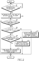
- FIG. 3 illustrates a procedure in which an MS passively determines communication resources through channel monitoring according to an embodiment of the present invention.
- the MS 100 detects a packet through channel monitoring in step 301, and confirms a destination address of the packet detected through the channel monitoring in step 303.
- the MS 100 checks whether the destination address of the detected packet is an address of the MS itself.
- the MS 100 receives a header of the packet, and then, continuously receives and decodes a payload of the packet. That is, when the destination address included in the header of the detected packet is identical to the adddress of the MS itself, the MS 100 may additionally receive a payload which follows the header of the relevant packet, and may communicate with said another MS 102, that has transmitted the relevant packet, according to a standard specification. Thereafter, the MS 100 terminates the passive communication resource determination procedure according to an embodiment of the present invention.
- the MS that has terminated the passive communication resource determination procedure, may again perform a passive communication resource determination procedure or may perform an active communication resource determination procedure.
- the MS 100 allocates a period, which corresponds to a period of the detected packet, as a cover interval. For example, the MS 100 may confirm information on a channel period included in the header of the detected packet, and may determine the confirmed channel period as a cover interval.
- the MS 100 may recognize that a packet, that the MS 100 needs to receive from said another MS 102, does not exist during the relevant channel period.
- the MS 100 may perform data communication with the cover during the allocated cover interval, in step 309, and checks whether additional resources are required, in step 311.
- the MS 100 may determine whether additional resources are required, on the basis of communication throughput between the MS 100 and the cover 104. Also, the MS 100 may determine whether a situation requires additional resources, on the basis of the amount of data transmitted/received between the MS 100 and the conver 104 and a period corresponding to the allocated cover interval. When it is determined that the additional resources are not required, the MS 100 terminates the passive communication resource determination procedure according to an embodiment of the present invention.
- the MS 100 proceeds to step 313 in which the MS 100 occupies a channel period through contention and allocates the occupied channel period as a cover interval.
- a configuration in which the MS 100 occupies a channel period through contention and allocates the occupied channel period as a cover interval may be performed in a scheme similar to that of steps 403 to 405 of FIG. 4 below.
- the MS 100 terminates the passive communication resource determination procedure according to an embodiment of the present invention.
- FIG. 4 illustrates a procedure in which an MS actively determines communication resources through channel monitoring according to an embodiment of the present invention.
- the MS 100 detects a situation in which a channel is not occupied, through channel monitoring. For example, when no packet is received through channel monitoring, the MS 100 may confirm that another MS that is connected to a channel or desires to access the channel does not exist, and may determine that said another MS does not occupy the channel.
- the MS 100 transmits a channel occupation signal, which includes a particular period value, to other neighboring MSs.
- the MS may transmit an RTS signal or a self-CTS signal, which includes information on a channel period to be used to communicate with the cover, to other neighboring MSs.
- the other neighboring MSs that have received the RTS signal or the self-CTS signal from the MS 100, recognize that the relevant MS is performing communication during a relevant channel period, and do not attempt to communicate with the MS during the relevant channel period.
- the MS 100 proceeds to step 405, and allocates a particular period, which corresponds to the particular period value included in the channel occupation signal, as a cover interval. Then, the MS 100 proceeds to step 407 in which the MS 100 performs data communication with the cover 104 during a period corresponding to the allocated cover interval. Then, the MS 100 terminates the active communication resource determination procedure according to an embodiment of the present invention.
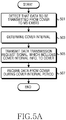
- the MS 100 detects that data to be transmitted from the cover 104 to the MS 100 exists, and determines a cover interval in step 503.
- the cover 104 according to an embodiment of the present invention communicates with only a predetermined MS or an MS located within a threshold distance, and thus has difficulty in autonomously acquiring resources. Accordingly, in an embodiment of the present invention, the MS 100 detects a case where data to be transmitted from the cover 104 to the MS 100 exists, and determines a cover interval for communicating with the cover 104.
- the MS 100 transmits a data transmission request signal, which includes cover interval information, to the cover 104.
- the data transmission request signal including cover interval information may be configured as illustrated in FIG. 5D .
- the data transmission request signal including cover interval information may include element identification information (element ID) 530 representing cover identification information, length information 532 of a message, the number of allocated cover intervals (number of allocations) 534, time offsets (time offset #N) 536-1 and 536-2 representing start points of respective cover intervals, periods (cover interval duration #N) 538-1 and 538-2 of the respective cover intervals, and pieces of transmission direction information (direction info #N) 540-1 and 540-2 of the respective cover intervals.
- element ID element identification information
- length information 532 of a message the number of allocated cover intervals (number of allocations) 534
- time offsets (time offset #N) 536-1 and 536-2 representing start points of respective cover intervals
- the number of allocated cover intervals may represent the number of the divided time periods. For example, when cover intervals are a period of 0 to 5 seconds, a period of 30 to 40 seconds, a period of 45 to 50 seconds, the number of cover intervals may be represented as being three. Also, a time offset, an interval period, and transmission direction information signifies information may be repeatedly included by the number of cover intervals. Further, here, the transmission direction information signifies information which indicates a period during which the MS 100 transmits a signal to the cover 104 or a period during which the cover 104 transmits a signal to the MS 100.
- FIG. 5B illustrates a procedure in which a cover communicates with an MS according to an embodiment of the present invention.
- the cover 104 receives a data transmission request signal, which includes cover interval information, from the MS 100.
- the data transmission request signal may be configured as illustrated in FIG. 5D .
- the cover 104 acquires the cover interval information from the data transmission request signal in step 513, and transmits data to the MS 100 during a cover interval period in step 515.
- FIG. 5C illustrates a communication procedure between an MS and a cover according to an embodiment of the present invention.
- the MS 100 detects the existence of data that the cover 104 is to transmit to the MS 100, and monitors a channel in order to allocate a cover interval in step 520. Then, in step 522, the MS 100 acquires cover interval information through passive resource allocation or active resource allocation on the basis of a result of monitoring the channel. For example, the MS 100 may confirm a channel period used for communication between said another MS 102 and still another MS, from a packet that said another MS 102 located adjacent to the MS 100 has transmitted, and may allocate the confirmed channel period as a cover interval.
- the MS 100 may detect that an MS that occupies a channel does not exist, may transmit an RTS or self-CTS signal and may occupy a channel period, and may allocate the occupied channel period as a cover interval.
- the MS 100 may transmit a data transmission request signal, which includes cover interval information, to the cover 104.
- the data transmission request signal including cover interval information may be configured as illustrated in FIG. 5D .
- the MS 100 may receive data from the cover 104 during a cover interval period in step 526, and may transmit an ACK message, which notifies of the successful reception of the data, to the cover 104 in step 528.
- the MS 100 transmits data from the cover 104 to the MS 100 with reference to FIGs. 5A to 5D .
- the above-described embodiment of the present invention may be similarly applied to a case where the MS 100 transmits data to the cover 104.
- the MS 100 may monitor a channel and may acquire a cover interval, and may transmit information on the cover interval to the cover 104.
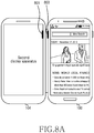
- FIG. 6A illustrates a procedure in which an MS changes a communication state of a cover according to an embodiment of the present invention.
- the MS 100 checks whether a cover communication interruption event is detected.
- the cover communication interruption event may be generated by a user input.
- the MS 100 may detect the selection of a menu by a user, the execution of a gesture by the user, or the input of a touch by the user which are for interrupting communication between the MS 100 and the cover 104.
- the MS 100 may display a message which inquires of the user about whether the user is to interrupt the cover image reproduction as illustrated in FIG.
- the MS 100 may display an icon for controlling (e.g., interrupting or restarting) the cover image reproduction, and may receive an input for interrupting the cover image reproduction from the user.
- the MS 100 may detect a cover communication interruption event on the basis of the battery residual quantity of the MS 100, the battery residual quantity of the cover 104, and whether data exists.
- the MS 100 may detect may detect the occurrence of the cover communication interruption event.
- the MS 100 may receive information on battery residual quantity from the cover 104 while communicating with the cover 104, or may include a separate means that detects the battery residual quantity of the cover 104.
- the MS 100 proceeds to step 603 in which the MS 100 determines a sleep duration and an awake duration.
- the sleep duration is a period during which a communication module of the cover 104 is turned off
- the awake duration is a period during which the communication module of the cover 104 is turned on.
- the sleep duration and the awake duration may be predetermined.
- the MS 100 transmits, to the cover 104, information on the sleep duration and the awake duration.
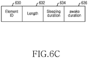
- a signal for transmitting the information on the sleep duration and the awake duration may be configured as illustrated in FIG. 6C .
- a message for transmitting the information on the sleep duration and the awake duration may include element identification information (element ID) 630 representing cover identification information, length information 632 of the relevant message, information on a sleeping duration 634 and an awake duration 636.
- FIG. 6B illustrates a procedure in which a cover changes a communication state according to the control of an MS according to an embodiment of the present invention.
- the cover 104 receives, from the MS 100, information on a sleep duration and an awake duration.
- the cover 104 may receive a message illustrated in FIG. 6C , and may acquire information on a sleep duration and an awake duration, from the received message.
- step 613 the cover 104 determines whether a current time point corresponds to the sleep duration.
- the cover 104 proceeds to step 617 in which the cover 104 turns off power of the communication module included in the cover 104, and performs step 615.
- the cover 104 may determine that a signal is not received from the MS 100 during the sleep duration, and may turn off power of the communication module in order to reduce power consumption during the sleep duration.
- the cover 104 proceeds to step 615 in which the cover 104 checks whether the current time point corresponds to the awake duration.
- the cover 104 returns to step 613 in which the cover 104 may re-check whether the current time point corresponds to the sleep duration.
- the cover 104 proceeds to step 619 in which the cover 104 turns on power of the communication module included therein.
- the cover 104 may determine that a signal is likely to be received from the MS 100 during the awake duration, and may turn on power of the communication module in order to detect the reception of a signal from the MS 100 during the awake duration.
- step 621 the cover 104 checks whether a signal is received from the MS 100. When the signal is not received from the MS 100, the cover 104 returns to step 613, and again performs the steps after step 613. In contrast, when the signal is received from the MS 100, in step 623, the cover 104 may maintain the power-on state of the communication module and may communicate with the MS 100. At this time, the cover 104 may acquire cover interval information from the MS 100, and may transmit or receive data during a cover interval period.
- step 625 the cover 104 checks whether the communication with the MS 100 has been terminated. When the communication with the MS 100 has not been terminated, the cover 104 may return to step 623, and may again perform the steps after step 623. When the communication with the MS 100 has been terminated, the cover 104 may return to step 613, and may again perform the steps after step 613.
- FIG. 7A illustrates a procedure in which an MS communicates with a cover by using a particular predetermined beam direction according to an embodiment of the present invention.
- step 701 the MS 100 checks whether a current time point corresponds to a cover interval period.
- the MS 100 switches to a non-standard channel access mode.
- the MS 100 may not switch to a mode for communicating with said another MS 102 according to a standard specification during the cover interval period, but may switch to a mode for communicating with the cover 104 according to a non-standard specification.
- the MS 100 may set an antenna and beam direction to a preset cover communication direction in step 705, and may transmit/receive data during an allocated cover interval period without a channel monitoring procedure in step 707.
- the MS 100 may set an antenna beam direction of the MS 100 so as to face a direction in which the cover 104 is located.
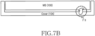
- the cover 104 may include an antenna 721 in an inner face that contacts a particular face of the MS 100.
- the MS 100 may set an antenna beam direction to the direction of the particular face which contacts the cover 104.
- the cover 104 includes the antenna 721 in the inner face that contacts the particular face of the MS 100 as illustrated in FIG.
- a rear face of the cover 104 may be designed to include an element that shields a radio wave, so as to radiate a radio wave from the antenna 721 to only the particular face of the MS 100.
- the antenna beam direction of the MS 100 which faces a direction in which the cover 104 is located may be preset in a design stage in view of the antenna of the cover 104, or may be set on the basis of information previously acquired from the cover 104.
- an antenna beam direction of the cover 104 may be fixed so as to face a face, which contacts the MS 100, without being changed.
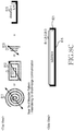
- FIG. 8A illustrates the installation position of an antenna of each of an MS and a cover according to an embodiment of the present invention.
- FIGs. 8B and 8C illustrate examples of a structure of the antenna of each of the MS and the cover according to an embodiment of the present invention.
- FIGs. 8A to 8C illustrate an antenna design structure for minimizing an effect that a communication signal between the MS 100 and the cover 104 exerts on communication of other MSs.
- the antenna 801 of the cover 104 and the antenna 803 of the MS 100 may be installed at locations illustrated in FIG. 8A . That is, the antenna 801 of the cover 104 may be mounted at a location adjacent to the MS 100, and the antenna 803 of the MS 100 may be mounted at a location adjacent to the antenna 801 of the cover 104. At this time, the antenna 803 of the MS 100 may be a dedicated antenna for cover communication, or may be an antenna used for both the cover communication and communication with another MS.
- an antenna for communication of each of the cover 104 and the MS 100 may include radiators 811, 812 and 813, and a shielding body 814 as illustrated in FIG. 8B , or may include the radiators 811, 812 and 813, and a cavity 815 as illustrated in FIG. 8C .
- the radiator according to an embodiment of the present invention may be configured in a meandering pattern, and the size of the radiator may be configured such that the maximum length of a polygon or a circle including the radiator satisfies Equation 1.
- the polygon or circle including the radiator may include a partial area of a substrate 821. D ⁇ ⁇ P 2
- D represents the maximum length of the polygon or circle including the radiator
- ⁇ represents the length of a wavelength according to a frequency
- P represents a distance between the antenna of the MS 100 and the antenna of the cover 104.
- P may represent a distance between the MS and the cover, and is conventionally equal to about 20 mm.
- Equation 1 is for causing the antennas used for communication between the MS 100 and the cover 104 to operate in a near-field area.
- the meandering pattern signifies that a conductive wire is bent and has a crank shape as in the first radiator 811 and the second radiator 812 illustrated in FIGs. 8B and 8C .
- the shielding body 814 may be formed of a metallic material having a mesh structure. At this time, a distance between the metallic material elements due to the mesh structure may be designed to be shorter than ⁇ /8. This configuration is for shielding a radio wave radiated from the radiator.
- the antenna that includes the radiators 811, 812 and 813, and the shielding body 814 may include the substrate 821.
- the radiators 811, 812, and 813 may be designed on one surface of the substrate 821, and the shielding body 814 may be designed on the other surface of the substrate 821.
- the cavity 815 may be formed of a conductive material as illustrated at the right of FIG. 8C .
- the height of the cavity 815 may be designed to be less than ⁇ /4.
- the antenna that includes the radiators 811, 812, or 813, and the cavity 815 may include the substrate 821.
- the radiators 811, 812, and 813 may be designed on one surface of the substrate 821, and the remaining three surfaces may be shielding-processed as the cavity 815.
- FIG. 9 illustrates a block configuration of an MS according to an embodiment of the present invention.
- the controller 900 controls and processes an overall function of operating the MS 100.
- the controller 900 controls a function of communicating with another unspecified MS located around the MS 100, and controls and processes a function of communicating with a particular device such as the cover 104.
- the controller 900 includes a cover communication controller 902; and determines a cover interval for communicating with the cover 104, and controls and processes a function of communicating with the cover 104 on the basis of the cover interval.
- the cover communication controller 902 may determine a period (e.g., IFS, SIFS, DIFS, or guard time period), that other MSs do not use, as a cover interval according to a standard specification, and may determine a channel period, that other MSs occupy, as a cover interval.
- the cover communication controller 902 may occupy a channel period through the transmission of a signal for occupying a channel, and may determine the occupied channel period as a cover interval. Also, the cover communication controller 902 may control and process a function of transmitting information on the cover interval to the cover 104, may determine a sleep duration and an awake duration of the cover 104 in order to control a communication state of the cover 104, and may control and process a function of transmitting, to the cover 104, information on the determined sleep duration and awake duration. Further, the cover communication controller 902 controls and processes a function of adjusting the antenna 920 and/or a transmission/reception beam direction in order to communicate with the cover 104.
- the communication unit 910 communicates with another MS, a base station, or the cover 104, that is located around the MS 100, according to the control of the controller 900.
- the communication unit 910 may include one communication modem.
- the communication unit 910 may transmit/receive data to/from the cover 104 with preset low power during a cover interval.
- the communication unit 910 may adjust the direction of the antenna 920 and/or a transmission/reception beam direction thereof in order to communicate with the cover 104 according to the control of the controller 900.
- the antenna 920 may be a beam antenna or an antenna array that is capable of forming a beam in a particular beam direction.
- the antenna 920 may include the radiators 811, 812 and 813, and the shielding body 814 as illustrated in FIG. 8B , or may include the radiators 811, 812 and 813, and the cavity 815 as illustrated in FIG. 8C .
- the storage unit 930 stores various data and programs for an overall operation of the MS 100. According to an embodiment of the present invention, the storage unit 930 may store information on a cover interval, and may store information on a sleep duration and an awake duration. Also, the storage unit 930 may include information on power used to communicate with the cover 104.
- the output unit 950 may output picture data, image data, or voice data to the user.
- the output unit 950 may include a display apparatus that displays picture data or image data, and a speaker that outputs voice data.
- the display apparatus may display a graphic element representing communication with the cover 104, or a graphic element representing the interruption of communication with the cover 104.
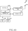
- the cover 104 may include a controller 1000, a communication unit 1010, an antenna 1020, a storage unit 1030, an input unit 1040, and an output unit 1050.
- the controller 1000 controls and processes an overall function of operating the cover 104.
- the controller 1000 controls and processes a function of outputting data, which is received from the MS 100, through the output unit 1050, or a function of storing data, which is received from the MS 100, in the storage unit 1030.
- an MS communication controller 1002 controls and processes a function of receiving, from the MS 100, cover interval information for communicating with the MS 100, and a function of communicating with the MS 100 on the basis of a cover interval.
- the MS communication controller 1002 controls a function of receiving, from the MS 100, information on a sleep duration and an awake duration of the cover 104, a function of turning off power of a communication module included in the communication unit 1010 during the sleep duration, and a function of turning on power of the communication module during the awake duration.
- the communication unit 1010 communicates with the particular preset MS 100 according to the control of the controller 1000. For example, according to the control of the controller 1000, the communication unit 1010 may transmit/receive data to/from the particular MS 100 with preset low power during a cover interval.
- the antenna 1020 may be a beam antenna or an antenna array that is capable of forming a beam in a particular beam direction.
- the antenna 1020 may include the radiators 811, 812 and 813, and the shielding body 814 as illustrated in FIG. 8B , or may include the radiators 811, 812 and 813, and the cavity 815 as illustrated in FIG. 8C .
- the storage unit 1030 stores various data and programs for communicating with the MS 100. According to an embodiment of the present invention, the storage unit 1030 may store information on a cover interval, and may store information on a sleep duration and an awake duration. Also, the storage unit 1030 may include information on power used for communication between the cover 104 and the MS 100. Further, the storage unit 1030 may store data received from the MS 100.
- the input unit 1040 delivers a command or data, which is generated by a selection or gesture made by the user, to the controller 1000.
- the input unit 940 may include at least one of at least one physical key button, a physical key pad, a touch detection sensor, a proximity sensor, an acceleration sensor, a microphone, and a mouse.
- the output unit 1050 may output picture data, image data, or voice data to the user.
- the output unit 1050 may include a display apparatus that displays picture data or image data, or a speaker that outputs voice data.
- the display apparatus according to an embodiment of the present invention may display a graphic element corresponding to data received from the MS 100.
- the operations according to embodiments of the present invention may be implemented by a single controller.
- program instructions for performing operations implemented by various computers may be recorded in a computer-readable medium.
- the computer-readable medium may include a program instruction, a data file, a data structure, and the like, alone or in a combination thereof.
- the program instructions may be especially designed and configured for the present invention, or may be known to and used by those skilled in the art.
- Examples of the computer-readable recording medium may include a magnetic medium such as a hard disk, a floppy disk, and a magnetic tape; an optical recording medium such as a Compact Disk Read Only Memory (CD-ROM) or a Digital Versatile Disk (DVD); a magneto-optical medium such as a floptical disk; and a hardware device specially configured to store and execute program instructions, such as a ROM, a Random Access Memory (RAM), a flash memory, and the like.
- Examples of the program instructions include a high-level language code, that a computer can execute by using an interpreter and the like, as well as a machine language code made by a compiler.
Landscapes
- Engineering & Computer Science (AREA)
- Signal Processing (AREA)
- Computer Networks & Wireless Communication (AREA)
- Health & Medical Sciences (AREA)
- Computing Systems (AREA)
- General Health & Medical Sciences (AREA)
- Medical Informatics (AREA)
- Human Computer Interaction (AREA)
- Mobile Radio Communication Systems (AREA)
Priority Applications (1)
| Application Number | Priority Date | Filing Date | Title |
|---|---|---|---|
| EP19215420.1A EP3641459B1 (de) | 2014-09-24 | 2015-09-23 | Von einer elektronischen vorrichtung durchgeführtes verfahren, von einer deckelvorrichtung durchgeführtes verfahren und elektronische vorrichtung |
Applications Claiming Priority (2)
| Application Number | Priority Date | Filing Date | Title |
|---|---|---|---|
| KR1020140127709A KR102098933B1 (ko) | 2014-09-24 | 2014-09-24 | 무선통신 시스템에서 디바이스간 통신 방법 및 장치 |
| PCT/KR2015/009986 WO2016048021A1 (ko) | 2014-09-24 | 2015-09-23 | 무선통신 시스템에서 디바이스간 통신 방법 및 장치 |
Related Child Applications (1)
| Application Number | Title | Priority Date | Filing Date |
|---|---|---|---|
| EP19215420.1A Division EP3641459B1 (de) | 2014-09-24 | 2015-09-23 | Von einer elektronischen vorrichtung durchgeführtes verfahren, von einer deckelvorrichtung durchgeführtes verfahren und elektronische vorrichtung |
Publications (2)
| Publication Number | Publication Date |
|---|---|
| EP3200531A1 true EP3200531A1 (de) | 2017-08-02 |
| EP3200531A4 EP3200531A4 (de) | 2017-10-25 |
Family
ID=55581460
Family Applications (2)
| Application Number | Title | Priority Date | Filing Date |
|---|---|---|---|
| EP19215420.1A Active EP3641459B1 (de) | 2014-09-24 | 2015-09-23 | Von einer elektronischen vorrichtung durchgeführtes verfahren, von einer deckelvorrichtung durchgeführtes verfahren und elektronische vorrichtung |
| EP15843957.0A Withdrawn EP3200531A4 (de) | 2014-09-24 | 2015-09-23 | Verfahren und vorrichtung zur kommunikation zwischen vorrichtungen in einem drahtloskommunikationssystem |
Family Applications Before (1)
| Application Number | Title | Priority Date | Filing Date |
|---|---|---|---|
| EP19215420.1A Active EP3641459B1 (de) | 2014-09-24 | 2015-09-23 | Von einer elektronischen vorrichtung durchgeführtes verfahren, von einer deckelvorrichtung durchgeführtes verfahren und elektronische vorrichtung |
Country Status (4)
| Country | Link |
|---|---|
| US (3) | US10334592B2 (de) |
| EP (2) | EP3641459B1 (de) |
| KR (1) | KR102098933B1 (de) |
| WO (1) | WO2016048021A1 (de) |
Families Citing this family (7)
| Publication number | Priority date | Publication date | Assignee | Title |
|---|---|---|---|---|
| KR102098933B1 (ko) | 2014-09-24 | 2020-04-08 | 삼성전자주식회사 | 무선통신 시스템에서 디바이스간 통신 방법 및 장치 |
| EP3294023B1 (de) * | 2015-06-02 | 2021-11-10 | Huawei Technologies Co., Ltd. | Verfahren und vorrichtung für ressourcenzuweisung |
| CN105872075B (zh) * | 2016-05-06 | 2018-08-31 | 东莞中科智城软件有限公司 | 一种将物联网设备映射到智慧城市资源模型的方法 |
| CN108882140B (zh) * | 2018-04-09 | 2021-10-22 | 北京小米松果电子有限公司 | 芯片获取定位的控制方法、装置及芯片 |
| KR102178308B1 (ko) * | 2019-12-11 | 2020-11-12 | 삼성전자 주식회사 | 무선 통신 시스템에서 디바이스간 통신 방법 및 장치 |
| WO2021211702A1 (en) * | 2020-04-15 | 2021-10-21 | XCOM Labs, Inc. | Wireless network multipoint association and diversity |
| EP4510756A4 (de) * | 2022-04-11 | 2026-03-18 | Lg Electronics Inc | Verfahren und vorrichtung zur übertragung von cot-informationen auf sl-u auf timerbasis |
Family Cites Families (17)
| Publication number | Priority date | Publication date | Assignee | Title |
|---|---|---|---|---|
| US8081964B1 (en) * | 2005-03-28 | 2011-12-20 | At&T Mobility Ii Llc | System, method and apparatus for wireless communication between a wireless mobile telecommunications device and a remote wireless display |
| US8160001B2 (en) * | 2006-05-25 | 2012-04-17 | Altair Semiconductor Ltd. | Multi-function wireless terminal |
| KR101545489B1 (ko) * | 2008-11-11 | 2015-08-19 | 엘지전자 주식회사 | 휴대단말기 |
| KR101587102B1 (ko) * | 2009-03-02 | 2016-01-20 | 엘지전자 주식회사 | 이동 단말기 |
| KR101564467B1 (ko) * | 2009-03-03 | 2015-10-29 | 엘지전자 주식회사 | 단말기에서의 데이터 표시 방법 및 이를 적용한 이동 통신 단말기 |
| JP5272917B2 (ja) * | 2009-06-18 | 2013-08-28 | 富士通株式会社 | 無線通信システム、端末装置、及び無線通信システムにおける無線通信方法 |
| US20110143769A1 (en) * | 2009-12-16 | 2011-06-16 | Microsoft Corporation | Dual display mobile communication device |
| KR101802522B1 (ko) | 2011-02-10 | 2017-11-29 | 삼성전자주식회사 | 복수의 터치스크린을 가지는 장치 및 복수의 터치스크린을 가지는 장치의 화면변경방법 |
| US8493897B2 (en) | 2011-02-11 | 2013-07-23 | Mediatek Inc. | Systems and methods for providing categorized channel reservation |
| JP5713844B2 (ja) * | 2011-08-25 | 2015-05-07 | 株式会社東芝 | 無線通信装置及び干渉回避方法 |
| WO2013036092A2 (ko) | 2011-09-09 | 2013-03-14 | 엘지전자 주식회사 | Wi-fi(wireless fidelity) p2p(peer to peer) 통신을 위한 방법 및 이를 위한 장치 |
| JP5915964B2 (ja) | 2011-09-14 | 2016-05-11 | ソニー株式会社 | 通信装置、通信システムおよび通信装置の制御方法 |
| US20130080932A1 (en) | 2011-09-27 | 2013-03-28 | Sanjiv Sirpal | Secondary single screen mode activation through user interface toggle |
| USD690678S1 (en) | 2012-01-11 | 2013-10-01 | Isaac S. Daniel | Communication device with flip cover for concealed biometric verification means |
| US20140078038A1 (en) * | 2012-09-14 | 2014-03-20 | Case Labs Llc | Systems and methods for providing accessory displays for electronic devices |
| US9699271B2 (en) * | 2013-01-29 | 2017-07-04 | Blackberry Limited | Method and apparatus for suspending screen sharing during confidential data entry |
| KR102098933B1 (ko) | 2014-09-24 | 2020-04-08 | 삼성전자주식회사 | 무선통신 시스템에서 디바이스간 통신 방법 및 장치 |
-
2014
- 2014-09-24 KR KR1020140127709A patent/KR102098933B1/ko not_active Expired - Fee Related
-
2015
- 2015-09-23 US US15/514,274 patent/US10334592B2/en active Active
- 2015-09-23 WO PCT/KR2015/009986 patent/WO2016048021A1/ko not_active Ceased
- 2015-09-23 EP EP19215420.1A patent/EP3641459B1/de active Active
- 2015-09-23 EP EP15843957.0A patent/EP3200531A4/de not_active Withdrawn
-
2019
- 2019-04-30 US US16/399,171 patent/US10477545B2/en active Active
- 2019-11-11 US US16/679,695 patent/US10993228B2/en active Active
Also Published As
| Publication number | Publication date |
|---|---|
| US10334592B2 (en) | 2019-06-25 |
| US20200077396A1 (en) | 2020-03-05 |
| EP3641459A1 (de) | 2020-04-22 |
| US10477545B2 (en) | 2019-11-12 |
| EP3200531A4 (de) | 2017-10-25 |
| KR102098933B1 (ko) | 2020-04-08 |
| US20190261365A1 (en) | 2019-08-22 |
| US20170273080A1 (en) | 2017-09-21 |
| EP3641459B1 (de) | 2024-03-06 |
| KR20160035862A (ko) | 2016-04-01 |
| EP3641459C0 (de) | 2024-03-06 |
| US10993228B2 (en) | 2021-04-27 |
| WO2016048021A1 (ko) | 2016-03-31 |
Similar Documents
| Publication | Publication Date | Title |
|---|---|---|
| US10993228B2 (en) | Method and apparatus for communication between devices in wireless communication system | |
| US11832188B2 (en) | Apparatus and method for controlling operation cycle of electronic device in wireless communication system | |
| US12526641B2 (en) | Channel assessment method and apparatus, communication device, and storage medium | |
| US10165510B2 (en) | Wireless communication device, wireless communication method, and wireless communication system | |
| EP3666030B1 (de) | Verfahren für wahlfreien zugriff auf der basis von mobilität und vorrichtung dafür | |
| JP6432104B2 (ja) | ライセンスバンド基地局装置、通信システム、通信制御方法およびプログラム | |
| CN111357320B (zh) | 通信处理方法、装置及计算机存储介质 | |
| CN112913308B (zh) | 在通信系统中使用非授权频段的方法和装置 | |
| KR102191366B1 (ko) | 무선통신 시스템에서 전자장치의 핸드오버 방법 및 장치 | |
| EP3301965A1 (de) | Verfahren und vorrichtungen zur herstellung einer backhaul-verbindung | |
| US20230224867A1 (en) | Technologies for inter-user equipment coordination | |
| KR101560603B1 (ko) | 제조물 및 정보 취급 시스템 | |
| EP4539587A1 (de) | Elektronische vorrichtung zur durchführung einer operation auf basis der latenz mehrerer verknüpfungen und betriebsverfahren einer elektronischen vorrichtung | |
| JP2023525282A (ja) | データ送信方法、装置、通信機器及び記憶媒体 | |
| KR102178308B1 (ko) | 무선 통신 시스템에서 디바이스간 통신 방법 및 장치 | |
| KR20210128248A (ko) | 데이터 송수신 방법 및 이를 지원하는 전자 장치 | |
| US20260095808A1 (en) | Transmitting buffer status reports in wireless networks in the presence of configured grants | |
| KR20200050854A (ko) | 무선 자원을 제어하기 위한 방법 및 전자 장치 | |
| KR20260025877A (ko) | 사전 스케줄링을 위한 일차 경로 상의 ul 승인 할당 | |
| CN107277910B (zh) | 射频干扰处理方法、装置、存储介质及终端 | |
| WO2024186541A1 (en) | Measurement reporting for secondary cell activation | |
| KR20220106556A (ko) | 복수 sim을 지원하는 전자 장치 및 그 동작 방법 | |
| WO2014048375A1 (zh) | 一种切换频谱的方法及设备 |
Legal Events
| Date | Code | Title | Description |
|---|---|---|---|
| STAA | Information on the status of an ep patent application or granted ep patent |
Free format text: STATUS: THE INTERNATIONAL PUBLICATION HAS BEEN MADE |
|
| PUAI | Public reference made under article 153(3) epc to a published international application that has entered the european phase |
Free format text: ORIGINAL CODE: 0009012 |
|
| STAA | Information on the status of an ep patent application or granted ep patent |
Free format text: STATUS: REQUEST FOR EXAMINATION WAS MADE |
|
| 17P | Request for examination filed |
Effective date: 20170424 |
|
| AK | Designated contracting states |
Kind code of ref document: A1 Designated state(s): AL AT BE BG CH CY CZ DE DK EE ES FI FR GB GR HR HU IE IS IT LI LT LU LV MC MK MT NL NO PL PT RO RS SE SI SK SM TR |
|
| AX | Request for extension of the european patent |
Extension state: BA ME |
|
| A4 | Supplementary search report drawn up and despatched |
Effective date: 20170921 |
|
| RIC1 | Information provided on ipc code assigned before grant |
Ipc: H04W 72/04 20090101AFI20170915BHEP |
|
| DAV | Request for validation of the european patent (deleted) | ||
| DAX | Request for extension of the european patent (deleted) | ||
| STAA | Information on the status of an ep patent application or granted ep patent |
Free format text: STATUS: EXAMINATION IS IN PROGRESS |
|
| 17Q | First examination report despatched |
Effective date: 20180507 |
|
| STAA | Information on the status of an ep patent application or granted ep patent |
Free format text: STATUS: THE APPLICATION IS DEEMED TO BE WITHDRAWN |
|
| 18D | Application deemed to be withdrawn |
Effective date: 20220210 |