EP3200510A1 - Station de base et station mobile - Google Patents
Station de base et station mobile Download PDFInfo
- Publication number
- EP3200510A1 EP3200510A1 EP15843460.5A EP15843460A EP3200510A1 EP 3200510 A1 EP3200510 A1 EP 3200510A1 EP 15843460 A EP15843460 A EP 15843460A EP 3200510 A1 EP3200510 A1 EP 3200510A1
- Authority
- EP
- European Patent Office
- Prior art keywords
- cell
- frequency band
- base station
- controller
- specific frequency
- Prior art date
- Legal status (The legal status is an assumption and is not a legal conclusion. Google has not performed a legal analysis and makes no representation as to the accuracy of the status listed.)
- Withdrawn
Links
Images


Classifications
-
- H—ELECTRICITY
- H04—ELECTRIC COMMUNICATION TECHNIQUE
- H04W—WIRELESS COMMUNICATION NETWORKS
- H04W72/00—Local resource management
- H04W72/04—Wireless resource allocation
- H04W72/044—Wireless resource allocation based on the type of the allocated resource
- H04W72/0453—Resources in frequency domain, e.g. a carrier in FDMA
-
- H—ELECTRICITY
- H04—ELECTRIC COMMUNICATION TECHNIQUE
- H04J—MULTIPLEX COMMUNICATION
- H04J11/00—Orthogonal multiplex systems, e.g. using WALSH codes
- H04J11/0069—Cell search, i.e. determining cell identity [cell-ID]
-
- H—ELECTRICITY
- H04—ELECTRIC COMMUNICATION TECHNIQUE
- H04L—TRANSMISSION OF DIGITAL INFORMATION, e.g. TELEGRAPHIC COMMUNICATION
- H04L5/00—Arrangements affording multiple use of the transmission path
- H04L5/003—Arrangements for allocating sub-channels of the transmission path
- H04L5/0032—Distributed allocation, i.e. involving a plurality of allocating devices, each making partial allocation
-
- H—ELECTRICITY
- H04—ELECTRIC COMMUNICATION TECHNIQUE
- H04L—TRANSMISSION OF DIGITAL INFORMATION, e.g. TELEGRAPHIC COMMUNICATION
- H04L5/00—Arrangements affording multiple use of the transmission path
- H04L5/003—Arrangements for allocating sub-channels of the transmission path
- H04L5/0048—Allocation of pilot signals, i.e. of signals known to the receiver
- H04L5/0051—Allocation of pilot signals, i.e. of signals known to the receiver of dedicated pilots, i.e. pilots destined for a single user or terminal
-
- H—ELECTRICITY
- H04—ELECTRIC COMMUNICATION TECHNIQUE
- H04W—WIRELESS COMMUNICATION NETWORKS
- H04W16/00—Network planning, e.g. coverage or traffic planning tools; Network deployment, e.g. resource partitioning or cells structures
- H04W16/14—Spectrum sharing arrangements between different networks
-
- H—ELECTRICITY
- H04—ELECTRIC COMMUNICATION TECHNIQUE
- H04W—WIRELESS COMMUNICATION NETWORKS
- H04W24/00—Supervisory, monitoring or testing arrangements
- H04W24/02—Arrangements for optimising operational condition
-
- H—ELECTRICITY
- H04—ELECTRIC COMMUNICATION TECHNIQUE
- H04W—WIRELESS COMMUNICATION NETWORKS
- H04W24/00—Supervisory, monitoring or testing arrangements
- H04W24/10—Scheduling measurement reports ; Arrangements for measurement reports
-
- H—ELECTRICITY
- H04—ELECTRIC COMMUNICATION TECHNIQUE
- H04W—WIRELESS COMMUNICATION NETWORKS
- H04W48/00—Access restriction; Network selection; Access point selection
- H04W48/08—Access restriction or access information delivery, e.g. discovery data delivery
- H04W48/12—Access restriction or access information delivery, e.g. discovery data delivery using downlink control channel
-
- H—ELECTRICITY
- H04—ELECTRIC COMMUNICATION TECHNIQUE
- H04W—WIRELESS COMMUNICATION NETWORKS
- H04W56/00—Synchronisation arrangements
- H04W56/001—Synchronization between nodes
- H04W56/0015—Synchronization between nodes one node acting as a reference for the others
-
- H—ELECTRICITY
- H04—ELECTRIC COMMUNICATION TECHNIQUE
- H04W—WIRELESS COMMUNICATION NETWORKS
- H04W72/00—Local resource management
- H04W72/50—Allocation or scheduling criteria for wireless resources
- H04W72/54—Allocation or scheduling criteria for wireless resources based on quality criteria
- H04W72/542—Allocation or scheduling criteria for wireless resources based on quality criteria using measured or perceived quality
-
- H—ELECTRICITY
- H04—ELECTRIC COMMUNICATION TECHNIQUE
- H04W—WIRELESS COMMUNICATION NETWORKS
- H04W74/00—Wireless channel access, e.g. scheduled or random access
- H04W74/002—Transmission of channel access control information
- H04W74/004—Transmission of channel access control information in the uplink, i.e. towards network
-
- H—ELECTRICITY
- H04—ELECTRIC COMMUNICATION TECHNIQUE
- H04W—WIRELESS COMMUNICATION NETWORKS
- H04W74/00—Wireless channel access, e.g. scheduled or random access
- H04W74/08—Non-scheduled or contention based access, e.g. random access, ALOHA, CSMA [Carrier Sense Multiple Access]
- H04W74/0833—Non-scheduled or contention based access, e.g. random access, ALOHA, CSMA [Carrier Sense Multiple Access] using a random access procedure
-
- H—ELECTRICITY
- H04—ELECTRIC COMMUNICATION TECHNIQUE
- H04W—WIRELESS COMMUNICATION NETWORKS
- H04W88/00—Devices specially adapted for wireless communication networks, e.g. terminals, base stations or access point devices
- H04W88/02—Terminal devices
- H04W88/06—Terminal devices adapted for operation in multiple networks or having at least two operational modes, e.g. multi-mode terminals
-
- H—ELECTRICITY
- H04—ELECTRIC COMMUNICATION TECHNIQUE
- H04B—TRANSMISSION
- H04B1/00—Details of transmission systems, not covered by a single one of groups H04B3/00 - H04B13/00; Details of transmission systems not characterised by the medium used for transmission
- H04B1/69—Spread spectrum techniques
- H04B1/713—Spread spectrum techniques using frequency hopping
-
- H—ELECTRICITY
- H04—ELECTRIC COMMUNICATION TECHNIQUE
- H04L—TRANSMISSION OF DIGITAL INFORMATION, e.g. TELEGRAPHIC COMMUNICATION
- H04L5/00—Arrangements affording multiple use of the transmission path
- H04L5/0001—Arrangements for dividing the transmission path
- H04L5/0003—Two-dimensional division
- H04L5/0005—Time-frequency
- H04L5/0007—Time-frequency the frequencies being orthogonal, e.g. OFDM(A), DMT
- H04L5/001—Time-frequency the frequencies being orthogonal, e.g. OFDM(A), DMT the frequencies being arranged in component carriers
-
- H—ELECTRICITY
- H04—ELECTRIC COMMUNICATION TECHNIQUE
- H04W—WIRELESS COMMUNICATION NETWORKS
- H04W52/00—Power management, e.g. TPC [Transmission Power Control], power saving or power classes
- H04W52/04—TPC
- H04W52/06—TPC algorithms
- H04W52/14—Separate analysis of uplink or downlink
- H04W52/146—Uplink power control
-
- H—ELECTRICITY
- H04—ELECTRIC COMMUNICATION TECHNIQUE
- H04W—WIRELESS COMMUNICATION NETWORKS
- H04W52/00—Power management, e.g. TPC [Transmission Power Control], power saving or power classes
- H04W52/04—TPC
- H04W52/18—TPC being performed according to specific parameters
- H04W52/24—TPC being performed according to specific parameters using SIR [Signal to Interference Ratio] or other wireless path parameters
- H04W52/242—TPC being performed according to specific parameters using SIR [Signal to Interference Ratio] or other wireless path parameters taking into account path loss
-
- H—ELECTRICITY
- H04—ELECTRIC COMMUNICATION TECHNIQUE
- H04W—WIRELESS COMMUNICATION NETWORKS
- H04W56/00—Synchronisation arrangements
-
- H—ELECTRICITY
- H04—ELECTRIC COMMUNICATION TECHNIQUE
- H04W—WIRELESS COMMUNICATION NETWORKS
- H04W88/00—Devices specially adapted for wireless communication networks, e.g. terminals, base stations or access point devices
- H04W88/08—Access point devices
- H04W88/10—Access point devices adapted for operation in multiple networks, e.g. multi-mode access points
Definitions
- the present application relates to a base station and a mobile station which are used in a mobile communication system.
- the unlicensed band is a frequency band which can be used without allowance.
- the license shared band is a frequency band which can be shared with an existing licensed person while changing time, place, or frequency.
- the white space is a frequency band allocated to a user who uses the frequency for one purpose such as digital television broadcasting (referred to as a "primary user of the frequency"), but it is a frequency band available for other users who use the frequency for another purpose depending on geographical conditions and technical conditions (referred to as a "secondary user of the frequency").
- the unlicensed band and the license shared band are called a specific frequency band.
- Non Patent Document 1 3GPP Technical Specification "TS36.300 V12.0.0" (January 2014 )
- the specific frequency band described above is not allowed to the primary user of the frequency by a mobile network operator, and cannot be occupied by one mobile network operator (that is, the unlicensed band). Therefore, it is difficult to apply the specific frequency band to the mobile communication.
- Abase station comprises a controller configured to manage a first cell operated using an allocation frequency band allocated by a mobile network operator and a second cell operated using a specific frequency band where occupying a frequency is not allowed by the mobile network operator.
- the controller set the second cell with a physical cell identifier different from a physical cell identifier of a peripheral cell operated in the specific frequency band.
- the controller may acquire the physical cell identifier of the peripheral cell and may set the second cell with a physical cell identifier different from the acquired physical cell identifier.
- the controller may acquire the physical cell identifier of the peripheral cell from a mobile station existing in the first cell.
- the controller acquires the physical cell identifier of the peripheral cell by searching the peripheral cell by the base station.
- a physical cell identifier used for the specific frequency band includes an extended region which is extended compare to a physical cell identifier used for the allocation frequency band.
- the controller may set the second cell with the physical cell identifier used for the specific frequency band.
- a physical cell identifier used for the specific frequency band and a physical cell identifier used for the allocation frequency band are secured individually.
- the controller may set the second cell with the physical cell identifier used for the specific frequency band.
- the controller may reset the second cell with another physical cell identifier.
- a mobile station comprises a controller configured to perform communication with a base station that manages a first cell operated using an allocation frequency band allocated by a mobile network operator and a second cell operated using a specific frequency band where occupying a frequency is not allowed by the mobile network operator.
- the controller performs processes of: acquiring a physical cell identifier of a peripheral cell operated in the specific frequency band, and transmitting information based on the acquired physical cell identifier to the base station.
- the controller may perform a process of transmitting, in response to an instruction from the base station, a physical cell identifier of the peripheral cell to the base station.
- the controller may transmit a detection report indicating the overlap to the base station.
- a base station comprises a controller configured to manage a first cell operated using an allocation frequency band allocated by a mobile network operator and a second cell operated using a specific frequency band where occupying a frequency is not allowed by the mobile network operator.
- the controller performs processes of transmitting a synchronization signal used for the allocation frequency band through the first cell, and transmitting a synchronization signal used for the specific frequency band through the second cell.
- a signal configuration of the synchronization signal used for the specific frequency band is different from a signal configuration of the signal used for the allocation frequency band.
- the synchronization signal used for the allocation frequency band consists a first synchronization signal and a second synchronization signal.
- the synchronization signal used for the specific frequency band may include the first synchronization signal, the second synchronization signal and a specific synchronization signal used dedicated for the specific frequency band.
- a predetermined resource arrangement pattern is applied to the synchronization signal used for the allocation frequency band.
- a resource arrangement pattern different from the predetermined resource arrangement pattern is applied to the synchronization signal used for the specific frequency band.
- a mobile station comprises a controller configured to perform communication with a base station that manages a first cell operated using an allocation frequency band allocated by a mobile network operator and a second cell operated using a specific frequency band where occupying a frequency is not allowed by the mobile network operator.
- a signal configuration of the synchronization signal used for the specific frequency band is different from a signal configuration of the signal used for the allocation frequency band.
- the controller specifies a synchronization signal of the second cell on the basis of the difference of the signal configurations.
- a base station comprises a controller configured to manage a first cell operated using an allocation frequency band allocated by a mobile network operator and a second cell operated using a specific frequency band where occupying a frequency is not allowed by the mobile network operator.
- the controller allocates a plurality of component carriers included in the specific frequency band to a mobile station.
- the controller performs communication with the mobile station while switching a component carrier used in a communication with the mobile station in the second cell, with a predetermined hopping pattern.
- the controller may notify, through the first cell, the mobile station of the plurality of component carriers allocated to the mobile station and the predetermined hopping pattern.
- the controller may notify the mobile station of an association between the virtual component carrier number and a component carrier that is actually used in a communication with the mobile station.
- the virtual component carrier number is associated with a retransmission control process.
- the controller may continue the retransmission control process associated with the virtual component carrier number even if the controller changes the component carrier that is actually used.
- a mobile station comprises a controller configured to perform communication with a base station that manages a first cell operated using an allocation frequency band allocated by a mobile network operator and a second cell operated using a specific frequency band where occupying a frequency is not allowed by the mobile network operator.
- the controller performs communication with the base station while switching a component carrier used in a communication with the base station in the second cell, with a predetermined hopping pattern.
- a base station comprises a controller configured to manage a first cell operated using an allocation frequency band allocated by a mobile network operator and a second cell operated using a specific frequency band where occupying a frequency is not allowed by the mobile network operator.
- the controller performs processes of: transmitting to a mobile station through the first cell, an instruction signal that instructs transmission of a random access preamble through the second cell; and notifying the mobile station, an offset value of uplink transmission timing used in a communication in the second cell, on the basis of the random access preamble received from the mobile station through the second cell.
- the controller may instruct the mobile station an uplink transmission power used in the communication in the second cell, at a time when notifying the mobile station of the offset value of uplink transmission timing.
- a mobile station comprises a controller configured to perform communication with a base station that manages a first cell operated using an allocation frequency band allocated by a mobile network operator and a second cell operated using a specific frequency band where occupying a frequency is not allowed by the mobile network operator.
- the controller performs processes of: in response to receiving, an instruction signal that instructs transmission of a random access preamble through the second cell, through the first cell, transmitting the random access preamble through the second cell; and receiving, from the base station, an offset value of uplink transmission timing used in a communication in the second cell.
- a mobile station comprises a controller configured to perform communication with a base station that manages a first cell operated using an allocation frequency band allocated by a mobile network operator and a second cell operated using a specific frequency band where occupying a frequency is not allowed by the mobile network operator. in response to receiving from the base station, a measurement instruction of a reference signal transmitted through the second cell, the controller estimates a path loss between the base station and the mobile station on the basis of the reference signal, and determines an uplink transmission power used in a communication in the second cell on the basis of the path loss.
- a base station comprises: a controller configured to manage a first cell operated using an allocation frequency band allocated by a mobile network operator and a second cell operated using a specific frequency band where occupying a frequency is not allowed by the mobile network operator.
- the controller performs processes of: transmitting to a mobile station, a measurement instruction of a reference signal transmitted through the second cell, in response to receiving a measurement result of the reference signal from the mobile station, determining, on the basis of the reception result, an uplink modulation and coding scheme used in a communication in the second cell.
- a base station comprises a controller configured to manage a first cell operated using an allocation frequency band allocated by a mobile network operator and a second cell operated using a specific frequency band where occupying a frequency is not allowed by the mobile network operator. During a predetermined time period from the end of data transmission to a mobile station in the second cell to performing transmission of reference signal, the controller stops transmission in the second cell and monitors interruption of other apparatuses in the specific frequency band.
- FIG. 1 is a configuration diagram of an LTE system according to a first embodiment.
- the LTE system according to the first embodiment includes User Equipment (UE) 100, an Evolved-UMTS Terrestrial Radio Access Network (E-UTRAN) 10, and an Evolved Packet Core (EPC) 20.
- UE User Equipment
- E-UTRAN Evolved-UMTS Terrestrial Radio Access Network
- EPC Evolved Packet Core
- the UE 100 corresponds to a mobile station.
- the UE 100 is a mobile communication device and performs radio communication with a cell (serving cell) of connection destination.
- the configuration of the UE 100 will be described below.
- the E-UTRAN 10 corresponds to a radio access network.
- the E-UTRAN 10 includes evolved Node-Bs (eNBs) 200.
- the eNB 200 corresponds to a base station.
- the eNBs 200 are connected to each other through an X2 interface. The configuration of the eNB 200 will be described below.
- the eNB 200 manages one or plural cells and performs radio communication with the UE 100 that establishes a connection with a cell of the eNB 200.
- the eNB 200 has, for example, a radio resource management (RRM) function, a routing function of user data, and a measurement control function for mobility control and scheduling.
- RRM radio resource management
- the "cell” is used as a term indicating a minimum unit of a radio communication area and is also used as a term indicating a function or resources of performing radio communication with the UE 100.
- the EPC 20 corresponds to a core network.
- a network of the LTE system is configured by the E-UTRAN 10 and the EPC 20.
- the EPC 20 includes Mobility Management Entity (MME)/Serving-Gateway (S-GW) 300.
- MME Mobility Management Entity
- S-GW Serving-Gateway
- the MME performs, for example, various mobility controls on the UE 100.
- the SGW performs transfer control of user data.
- the MME/S-GW 300 is connected to the eNB 200 through an S1 interface.
- FIG. 2 is a block diagram of the UE 100.
- the UE 100 includes plural antennas 101, a radio transceiver 110, a user interface 120, a Global Navigation Satellite System (GNSS) receiver 130, a battery 140, a memory 150, and a processor 160.
- the memory 150 corresponds to a storage
- the processor 160 corresponds to a controller.
- the UE 100 may not include the GNSS receiver 130.
- the memory 150 may be integrally formed with the processor 160, and this integrated set (that is, chipset) may be called a processor 160'.
- the antennas 101 and the radio transceiver 110 are used to transmit and receive a radio signal.
- the radio transceiver 110 converts a baseband signal (transmission signal) output from the processor 160 into the radio signal, and transmits the radio signal from the antenna 101. Furthermore, the radio transceiver 110 converts the radio signal received by the antenna 101 into the baseband signal (reception signal), and outputs the baseband signal to the processor 160.
- the user interface 120 is an interface with a user carrying the UE 100, and includes, for example, a display, a microphone, a speaker, and various buttons.
- the user interface 120 receives an operation from a user and outputs a signal indicating the content of the operation to the processor 160.
- the GNSS receiver 130 receives a GNSS signal in order to obtain location information indicating a geographical location of the UE 100, and outputs the received signal to the processor 160.
- the battery 140 accumulates power to be supplied to each block of the UE 100.
- the memory 150 stores a program to be executed by the processor 160 and information to be used for a process by the processor 160.
- the processor 160 includes a baseband processor that performs modulation and demodulation, encoding and decoding and the like of the baseband signal, and a Central Processing Unit (CPU) that performs various processes by executing the program stored in the memory 150.
- the processor 160 may further include a codec that performs encoding and decoding of sound and video signals.
- the processor 160 implements various processes and various communication protocols described later.
- FIG. 3 is a block diagram of the eNB 200.
- the eNB 200 includes antennas 201, a radio transceiver 210, a network interface 220, a memory 230, and a processor 240.
- the memory corresponds to a memory unit.
- the processor 240 corresponds to a controller.
- the controller may be constituted by the memory 230 and the processor 240.
- the antennas 201 and the radio transceiver 210 are used to transmit and receive a radio signal.
- the radio transceiver 210 converts the baseband signal (transmission signal) output from the processor 240 into the radio signal, and transmits the radio signal from the antenna 201. Furthermore, the radio transceiver 210 converts the radio signal received by the antenna 201 into the baseband signal (reception signal), and outputs the baseband signal to the processor 240.
- the network interface 220 is connected to the adjacent eNB 200 through the X2 interface and is connected to the MME/S-GW 300 through the S1 interface.
- the network interface 220 is used in communication performed on the X2 interface and communication performed on the S1 interface.
- the memory 230 stores a program to be executed by the processor 240 and information to be used for a process by the processor 240.
- the processor 240 includes the baseband processor that performs modulation and demodulation, encoding and decoding and the like of the baseband signal and a CPU that performs various processes by executing the program stored in the memory 230.
- the processor 240 implements various processes and various communication protocols described later.
- FIG. 4 is a protocol stack diagram of a radio interface in the LTE system.
- a radio interface protocol is classified into a first layer to a third layer of an OSI reference model, wherein the first layer is a physical (PHY) layer.
- the second layer includes a Medium Access Control (MAC) layer, a Radio Link Control (RLC) layer, and a Packet Data Convergence Protocol (PDCP) layer.
- the third layer includes a Radio Resource Control (RRC) layer.
- RRC Radio Resource Control
- the physical layer performs encoding and decoding, modulation and demodulation, antenna mapping and demapping, and resource mapping and demapping. Between the physical layer of the UE 100 and the physical layer of the eNB 200, user data and control signals are transmitted through a physical channel.
- the MAC layer performs preferential control of data, and a retransmission process and the like by hybrid ARQ (HARQ).
- HARQ hybrid ARQ
- the MAC layer of the eNB 200 includes a transport format of an uplink and a downlink (a transport block size and a modulation and encoding scheme) and a scheduler for determining (scheduling) a resource block to be assigned to the UE 100.
- the RLC layer transmits data to an RLC layer of a reception side using the functions of the MAC layer and the physical layer. Between the RLC layer of the UE 100 and the RLC layer of the eNB 200, user data and control signals are transmitted through a logical channel.
- the PDCP layer performs header compression and decompression, and encryption and decryption.
- the RRC layer is defined only in a control plane that handles control signals. Between the RRC layer of the UE 100 and the RRC layer of the eNB 200, control signals (RRC message) for various types of setting are transmitted.
- the RRC layer controls the logical channel, the transport channel, and the physical channel in response to establishment, reestablishment, and release of a radio bearer.
- RRC connection When a connection (RRC connection) is established between the RRC of the UE 100 and the RRC of the eNB 200, the UE 100 is in a connected state (RRC connected state), and when the RRC connection is not established, the UE 100 is in an idle state (RRC idle state).
- a Non-Access Stratum (NAS) layer positioned at an upper level of the RRC layer performs session management and mobility management
- FIG. 5 is a configuration diagram of a radio frame used in the LTE system.
- Orthogonal Frequency Division Multiple Access (OFDMA) is employed in a downlink (DL), and Single Carrier Frequency Division Multiple Access (SC-FDMA) is employed in an uplink (UL), respectively.
- OFDMA Orthogonal Frequency Division Multiple Access
- SC-FDMA Single Carrier Frequency Division Multiple Access
- the radio frame is configured by 10 subframes arranged in a time direction.
- Each subframe is configured by two slots arranged in the time direction.
- Each subframe has a length of 1 ms and each slot has a length of 0.5 ms.
- Each subframe includes a plurality of resource blocks (RBs) in a frequency direction, and a plurality of symbols in the time direction.
- Each of the resource blocks includes a plurality of subcarriers in the frequency direction.
- a resource element is configured by one subcarrier and one symbol.
- the frequency resource is configured by a resource block
- a time resource is configured by a subframe (or slot).
- an interval of several symbols at the head of each subframe is a region mainly used as a physical downlink control channel (PDCCH) for transmission of a downlink control signal. Furthermore, the remaining part of each subframe is a region mainly used as a physical downlink shared channel (PDSCH) for transmission of a downlink user data.
- PDCH physical downlink control channel
- PDSCH physical downlink shared channel
- both end portions in the frequency direction of each subframe are regions mainly used as a physical uplink control channel (PUCCH) for transmission of an uplink control signal.
- the remain portion of each subframe is a region that can be mainly used as a physical uplink shared channel (PUSCH) for transmission of an uplink user data.
- PUCCH physical uplink control channel
- PUSCH physical uplink shared channel
- a cell identifier for identifying a cell is assigned to each cell.
- the cell identifier includes a physical cell identifier (PCI), a cell global identifier (ECGI), and the like.
- the ECGI is configured by an MCC, an MNC, and an ECI.
- the ECI is configured by a combination of the PCI and an eNB identifier.
- the PCI is configured by 8 bits, and mainly used in the physical layer.
- the number of PCIs defined in the specifications is 504.
- 504 signal sequences of a cell-specific reference signal (CRS) are prepared, and the signal sequences are associated with PCIs.
- the UE 100 specifies the PCI of a cell by a primary synchronization signal (PSS) and a secondary synchronization signal (SSS) which are received from the cell.
- PSS primary synchronization signal
- SSS secondary synchronization signal
- a value of the PSS is associated with (three) cell IDs in a cell ID group
- a value of the SSS is associated with (168) cell ID groups
- the PCI is specified by a combination of the PSS and the SSS.
- the PSS and the SSS provide a downlink frame level synchronization.
- the UE 100 receives the CRS on the basis of the PCI after specifying the PCI of the cell by the combination of the PSS and the SSS.
- the CRS provides downlink symbol synchronization and frequency synchronization.
- the CRS is provided in a first OFDM symbol and a third-to-last OFDM symbol in a slot at six subcarrier intervals. Further, CRSs are divided into six frequency shift groups (CRS frequency shift group) depending on the PCI.
- the ECGI is broadcast from the cell by a system information block (SIB) that is exchanged in the RRC layer.
- SIB system information block
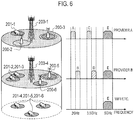
- FIG. 6 A system configuration in a case where a mobile network operator uses a specific frequency band will be described using FIG. 6 .
- FIG. 6 is a diagram illustrating a system configuration when the mobile network operators (a provider A and a provider B) and a WLAN (WiFi or the like) share a 5 GHz specific frequency band.
- the provider A, the provider B, and the WLAN share a 5 GHz unlicensed band E.
- the provider A provides a communication service using licensed bands A and C which can be occupied by the provider A and the unlicensed band E which cannot be occupied by the provider A.
- the provider B provides the communication service using licensed bands B and D which can be occupied by the provider B and the unlicensed band E which cannot be occupied by the provider B.
- the unlicensed band E is used even when the communication is performed using a public wireless LAN or using the WLAN by a person.
- the provider A provides a service using the licensed band A at an eNB 200-1, the licensed band C at an eNB 200-2, and the licensed band C and the unlicensed band E at an eNB 200-3.
- the provider A may provide the service using the unlicensed band E at a WLAN access point 201-1.
- the provider B provides a service using the licensed band B at an eNB 200-4, the licensed band D and the unlicensed band E at an eNB 200-5, and the unlicensed band E at an eNB 200-6.
- the provider B may provide the service using the unlicensed band E at WLAN access points (201-2, 201-3).
- the unlicensed band E is used for a public wireless LAN provider and WLAN access points (201-4, 201-5, 201-5) provided by a person.
- the service is provided simultaneously using the licensed band and the unlicensed band at the eNB 200-3 and the eNB 200-5.
- the eNB 200-3 and the eNB 200-5 form a licensed cell (L-Cell) and an unlicensed cell (U-Cell) using the licensed band.
- FIGS. 7 to 11B A method of setting the PCI of the U-Cell will be described using FIGS. 7 to 11B .
- a communication control method in this embodiment is a communication control method of an eNB 200 that includes a first cell (L-Cell) operated using an allocation frequency band (a licensed band) allocated to a mobile network operator and a second cell (U-Cell) operated using a specific frequency band (an unlicensed band) where occupying a frequency is not allowed by the mobile network operator.
- the communication control methods includes: acquiring, by the eNB 200, a physical cell identifier (PCI) of a peripheral cell operated in the specific frequency band; and setting, by the eNB 200, the second cell (U-Cell) with a physical cell identifier different from the acquired physical cell of the peripheral cell.
- PCI physical cell identifier
- the eNB 200 may acquire the physical cell identifier of the peripheral cell from a UE 100 located in an area of the first cell (L-Cell).
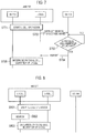
- FIG. 7 An operation of the eNB 200 to acquire the PCI of the peripheral cell from the UE 100 located in the area of the L-Cell will be described using FIG. 7 .
- Step S701 the eNB 200 determines the operation start of the U-Cell.
- Step S702 the eNB 200 determining the operation start of the U-Cell instructs, through the L-Cell, the UE 100 to search the unlicensed band.
- Step S703 the UE 100 receiving a command of searching the unlicensed band searches the unlicensed band.
- step S704 the UE 100 reports the search result of the unlicensed band to the eNB 200.
- the UE 100 does not report the search result to the eNB 200 in a case where the PCI of the peripheral U-Cell cannot be found out.
- Step S705 the eNB 200 receiving the report on the PCI of the peripheral U-Cell sets a PCI different from the PCI of the peripheral U-Cell to the U-Cell which starts the operation.
- the eNB 200 may acquire the physical cell identifier of the peripheral cell by searching the peripheral cell.
- Step S801 the eNB 200 determines an operation start of the U-Cell.
- Step S802 the eNB 200 searches the unlicensed band.
- Step S803 the eNB 200 acquiring the PCI of the peripheral U-Cell as a result of the searching sets a PCI different from the PCI of the peripheral U-Cell to the U-Cell which starts the operation.
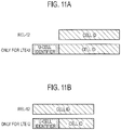
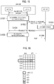
- an region for identifying the U-Cell may be added to a PCI format (general PCI format) which is used in the L-Cell.
- FIG. 11A An example of the PCI format of the U-Cell is illustrated in FIG. 11A .
- the upper portion of FIG. 11A is the PCI format which is used in the L-Cell of Release 12.
- the lower portion of FIG. 11A is an example of the PCI format which is used in the U-Cell.
- a U-Cell identifier is added to identify the U-Cell.
- a physical cell identifier used for the specific frequency band includes an extended region which is extended compare to a physical cell identifier used for the allocation frequency band (licensed band).
- the eNB 200 set the U-Cell with the physical cell identifier used for the specific frequency band.
- the eNB 200 transmits a synchronization signal used for the allocation frequency band (licensed band) through the first cell (L-Cell), and transmits a synchronization signal used for the specific frequency band (unlicensed band) through the second cell (U-Cell).
- a signal configuration of the synchronization signal used for the specific frequency band is different from a signal configuration of the signal used for the allocation frequency band.
- the UE 100 specifies a synchronization signal of the second cell on the basis of the difference of the signal configurations.
- the synchronization signal used for the allocation frequency band consists a first synchronization signal (PSS: Primary Synchronization Signal) and a second synchronization signal (SSS: Secondary Synchronization Signal).
- the synchronization signal used for the specific frequency band includes the first synchronization signal, the second synchronization signal and a specific synchronization signal used dedicated for the specific frequency band (See Fig. 9 ).
- a predetermined resource arrangement pattern may be applied to the synchronization signal used for the allocation frequency band, and a resource arrangement pattern different from the predetermined resource arrangement pattern may be applied to the synchronization signal used for the specific frequency band.
- PSS/SSS used for the specific frequency band are arranged in different location (frequency location or time location) than that in PSS/SSS used for the allocation frequency band
- the communication control method of this embodiment may include: receiving, by the UE 100, a primary synchronization signal (PSS) and a secondary synchronization signal (SSS) through the U-Cell from the eNB 200, the primary synchronization signal and the secondary synchronization signal being used in both of the L-Cell and the U-Cell, and receiving a specific synchronization signal (USS) for the specific frequency band (the unlicensed band); and specifying, by the UE 100, the U-Cell based on the received primary synchronization signal and the received secondary synchronization signal.
- PSS primary synchronization signal
- SSS secondary synchronization signal
- the USS U-Cell specific Synchronization Signal
- the UE 100 specifies the PCI of the U-Cell based on the PSS, the SSS, and the USS.
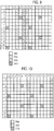
- FIG. 9 illustrates an example of the layout of the USS.
- the vertical direction is the frequency direction and the horizontal direction is the time direction.
- the USS is disposed in addition to the PSS, the SSS, and a cell specific reference signal (CRS).
- the USS is disposed in subcarriers #0 to #11 of the unlicensed band in a predetermined subframe.
- the USS is a synchronization signal to be used only on the U-Cell.
- a sequence number of an orthogonal code sequence for example, Zadoff-chu sequence
- the USS may indicate a public land mobile network (PLMN) identifier, or may indicate a mobile network code (MNC).
- PLMN public land mobile network
- MNC mobile network code
- An interval (offset) between the PSS/SSS and the USS may be fixed, or may be arbitrarily set. In a case where the interval is arbitrarily set, the interval (offset) may be notified through the L-Cell from the eNB 200.
- the PSS, the SSS, the CRS, and the USS may be called a discovery reference signal (DRS) for the U-Cell.
- DRS discovery reference signal
- the DRS may further include a Channel State Information-Reference Signal (CSI-RS).
- CSI-RS Channel State Information-Reference Signal
- the communication control method of this embodiment may include: receiving, by the UE 100, a primary synchronization signal (PSS) and a secondary synchronization signal (SSS) through the U-Cell from the eNB 200, the primary synchronization signal and the secondary synchronization signal being used in both of the L-Cell and the U-Cell; receiving, by the UE 100, an interval between the primary synchronization signal and the secondary synchronization signal through the L-Cell from the eNB 200; and specifying, by the UE 100, the U-Cell based on the received primary synchronization signal, the received secondary synchronization signal, and the interval.
- PSS primary synchronization signal
- SSS secondary synchronization signal
- the PCI of the U-Cell is specified based on the PSS, the SSS, and the interval by changing the interval (offset) between the PSS and the SSS. Further, the PLMN identifier and MNC may be specified by the interval.
- the eNB 200 set the U-Cell with the PCT used for the specific frequency band.
- FIG. 11B An example of the PCI format of the U-Cell in this case is illustrated in FIG. 11B .
- the upper portion of FIG. 11B illustrates the PCI format which is used in the L-Cell of Release 12.
- the lower portion of FIG. 11B illustrates the PCI format which is used in the U-Cell.
- a U-Cell identifier is provided in a portion of the existing PCI format in order to identify the U-Cell.
- the PCI can be set in each of the L-Cell and the U-Cell by dividing the range of the PCI which can be set in the L-Cell and the U-Cell.
- a communication control method between a UE 100 and an eNB 200 that includes a first cell (L-Cell) operated using a frequency band allocated to a mobile network operator and a second cell (U-Cell) operated using a specific frequency band where occupying a frequency is not allowed by the mobile network operator, including: setting, by the eNB 200, a physical cell identifier (PCI) to the U-Cell and starting an operation; detecting, by the eNB 200 or the UE 100, whether the PCI set to the U-Cell and a PCI of a peripheral cell are overlapped; and resetting, by the eNB 200, the U-Cell to another physical cell identifier in a case where the PCI is overlapped between the U-Cell and the peripheral cell.
- PCI physical cell identifier
- the eNB 200 is configured to reset the PCI in a case where the PCI is overlapped between the operating U-Cell and the peripheral cell.
- Step S1201 the eNB 200 determines to start the operation of the U-Cell.
- Step S1202 the eNB 200 determining the operation start of the U-Cell determines the physical cell identifier of the U-Cell.
- the eNB 200 may randomly determine the physical cell identifier of the U-cell.
- Step S1203 the eNB 200 performs an operation preparation process of the U-Cell.
- Step S1204 the eNB 200 starts the operation of the U-Cell. Specifically, the transmission of the DRS is started.
- Step S1205 the UE 100 receives the DRS of the U-Cell, and detects whether the PCI of the U-Cell is overlapped with the PCI of the peripheral cell.
- Step S1206 the UE 100 transmits a collision detection report through the L-Cell to the eNB 200.
- Step S1207 the eNB 200 receiving the collision detection report from the UE 100 resets the PCI of the U-Cell.
- the eNB 200 may randomly determine the physical cell identifier of the U-cell.
- the sequence at the time of the PCI collision illustrated in FIG. 12 can also applied to a resetting operation in a case where the DRSs are collided between the cells.
- the UE 100 may change its own transmission timing (for example, a rough position in a unit of subframe) such as a position of a synchronization signal, a broadcast channel, or a data channel in order to specify the U-Cell.
- a rough position in a unit of subframe such as a position of a synchronization signal, a broadcast channel, or a data channel in order to specify the U-Cell.
- the transmission timing of the peripheral cell is searched by the subject eNB 200 or the search result of the UE 100 is acquired, and the transmission timing is set not to be overlapped with that of the peripheral cell.
- the transmission timing is periodical in the U-Cell and the peripheral cell, it is desirable that the period be equal or the period of the transmission timing of the U-Cell be N times the transmission timing of the peripheral cell (N is an arbitrary integer).
- the eNB 200 allocates a plurality of component carriers included in the specific frequency band to the UE 100, and performs communication with the UE 100 while switching a component carrier used in a communication with the UE 100 in the second cell, with a predetermined hopping pattern.
- the eNB 200 notifies, through the first cell, the UE 100 of the plurality of component carriers allocated to the UE 100 and the predetermined hopping pattern.
- the UE 100 performs communication with the eNB 200 while switching a component carrier used in a communication with the eNB 200 in the second cell, with a predetermined hopping pattern.
- the eNB 200 is configured to use the specific frequency bandwidth by dividing the specific frequency bandwidth into a plurality of component carriers.
- the communication control method includes: notifying, by the eNB 200, the component carrier on the second cell to be used by the UE 100 through the first cell and a hopping pattern between the plurality of component carriers to the UE 100; and transmitting or receiving, by the UE 100, data on the second cell using the component carrier notified from the eNB 200.
- CC component carriers
- a unit of subframe or a unit of slot is desirable.
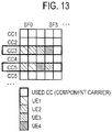
- FIG. 13 illustrates an exemplary allocation of the component carriers when the frequency hopping is performed between the component carriers.
- a UE 100-1 is allocated with CC #3 in Subframe (SF) #0, and CC #5 in Subframe #1.
- a UE 100-3 is allocated with CC #3 in Subframe #2, and CC #5 in Subframe #3.
- the eNB 200 When the frequency hopping is applied, the eNB 200 notifies a combination of the component carriers used in the U-Cell in a predetermined time period to the UE 100. In addition, the eNB 200 notifies information indicating whether the frequency hopping is applied to the UE 100. The notification is desirably included in resource allocation information for the data transmission.
- the UE 100 specifies the component carrier to be used in the predetermined time period using the acquired information, and performs transmission/reception of data.
- the eNB 200 After the eNB 200 notifies the UE 100 of a virtual component carrier number as configuration information of a component carrier allocated to the mobile station, the eNB 200 notifies the UE 100 of an association between the virtual component carrier number and a component carrier that is actually used in a communication with the mobile station.
- the virtual component carrier number is associated with a retransmission control process.
- the eNB 200 continues the retransmission control process associated with the virtual component carrier number even if the eNB changes the component carrier that is actually used.
- a communication control method in this embodiment includes: notifying, by the eNB 200, setting information of the plurality of component carriers through the first cell; notifying, by the eNB 200, the component carrier that is used by the UE 100 for transmitting or receiving data; and activating, by the UE 100, a retransmission data waiting timer in a case where the UE 100 fails to receive the data on the component carrier.
- the UE 100 receives retransmission data through any one of the plurality of component carriers while the retransmission data waiting timer is activated.
- the eNB 200 may notify a virtual number of the plurality of component carriers to the UE 100, and in the notifying of the component carrier to be used in transmitting or receiving the data, the eNB 200 may notify an association between the virtual number and the actually used component carrier to the UE 100.
- the component carrier on the unlicensed band is not in the frequency band allocated to the mobile network operator, the component carrier may become unusable during the communication between the UE 100 and the eNB 200. Therefore, in order to enable the process of the retransmission control (HARQ control) to be continuously usable on the unlicensed band, it is necessary that the HARQ control is kept continuous on another component carrier even when the component carrier during the communication becomes unusable.
- HARQ control retransmission control
- the above problem can be solved through that the eNB 200 transmits retransmission data through the usable component carrier and the UE 100 receives the retransmission data through any one of the component carriers on the unlicensed band.
- the UE 100 cannot receive data on the component carrier of the unlicensed band, and in a case where the retransmission becomes necessary, the retransmission is performed using the component carrier of the unlicensed band, and the retransmission is not performed using the component carrier on the licensed band.
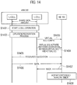
- Step S1401 the eNB 200 determines the operation start of the U-Cell.
- Step S1402 the eNB 200 performs an operation start preparation process of the U-Cell.
- Step S1403 the eNB 200 notifies a virtual SCC Config (the setting information of the component carrier on the unlicensed band) to the UE 100.
- the setting information for receiving broadcast information on the unlicensed band is included, but a frequency of the component carrier used for transmitting or receiving the data is not designated.
- Step S1404 the eNB 200 notifies the component carrier used for transmitting or receiving the data to the UE 100 (SCC Activate).
- the SCC Activate includes information in which the virtual SCC Config and the component carrier used for transmitting or receiving the data are associated.
- Step S1405 the eNB 200 performs the resource allocation on the component carrier on the unlicensed band with respect to the UE 100.
- Step S1406 the eNB 200 transmits the data to the UE 100.
- Step S1407 when failing to receive the data from the eNB 200, the UE 100 transmits a Nack signal to the eNB 200.
- Step S1408 the UE 100 activates an extended HARQ Rx timer when the Nack signal is transmitted, and receives the retransmission data through any one of the plurality of component carriers on the unlicensed band during the activation of the HARQ Rx timer.
- Step S1403 and Step S1404 may be simultaneously implemented.
- FIG. 14 illustrates the retransmission of downlink data, and the retransmission of uplink data is also the same.
- the extended HARQ Rx timer has the same function as the HARQ Rx timer of the LTE.
- the extended HARQ Rx timer can be set to a time (a timer value) longer than the HARQ Rx timer of the LTE in consideration of a time necessary for securing bandwidth on the unlicensed band.
- An eNB 200 performs processes of: transmitting to a UE 100 through a first cell (L-Cell), an instruction signal that instructs transmission of a random access preamble through a second cell (U-Cell); and notifying the UE 100, an offset value of uplink transmission timing used in a communication in the second cell, on the basis of the random access preamble received from the UE 100 through the second cell.
- the eNB 200 my instruct the UE 100 an uplink transmission power used in the communication in the second cell, at a time when notifying the UE 100 of the offset value of uplink transmission timing.
- the UE 100 performs processes of: in response to receiving, an instruction signal that instructs transmission of a random access preamble through the second cell (U-Cell), through the first cell (L-Cell), transmitting the random access preamble through the second cell; and receiving, from the eNB 200, an offset value of uplink transmission timing used in a communication in the second cell.
- a communication control method in this embodiment includes: transmitting, by the eNB 200 through the first cell to the UE 100, a command signal that instructs the UE 100 to transmit a random access preamble to the eNB 200 through the second cell and a transmission time of the random access preamble; searching, by the UE 100, the second cell according to the reception of the command signal; transmitting, by the UE 100, the random access preamble through the second cell to the eNB 200 at the transmission time instructed by the command signal in a case where the second cell is not detectable as a result of the searching; calculating, by the eNB 200, a timing offset value used in transmitting uplink data through the second cell based on timing when the random access preamble is received; and notifying, by the eNB 200, the timing offset value to the UE 100.
- the eNB 200 may instruct the UE 100 with transmission power at the time of transmitting the uplink data.
- Step S1501 the eNB 200 determines that the uplink data (UL data) from the UE 100 is received in the U-Cell.
- Step S1502 the eNB 200 instructs the UE 100 to transmit a random access preamble (RA Preamble) through the L-Cell.
- RA Preamble a random access preamble
- Step S1503 the UE 100 performs carrier sensing for the unlicensed band.
- Step S1504 the UE 100 transmits the RA preamble to the eNB 200 through the U-Cell detected by the carrier sensing.
- Step S1505 the eNB 200 receiving the RA preamble calculates a timing difference (calculation of TA (Timing Advance)).
- Step S1506 the eNB 200 transmits a random access response (RAR) through the L-Cell to the UE 100.
- RAR random access response
- the eNB 200 can appropriately allocate the resources for transmitting the uplink resource data using the calculated timing difference with respect to the UE 100.
- Step S1503 in a case where it is determined that the RA preamble cannot be transmitted at the time designated by the command signal as a result of the carrier sensing, the process of Step S1504 and the subsequent processes are stopped.
- the eNB 200 may estimate the UEs 100 for which the same TA (Timing Advance) can be applied to the licensed band and the unlicensed band from a measurement report for RRM (Radio Resource Management), and may select an appropriated UE 100.
- TA Transmission Advance
- RRM Radio Resource Management
- the uplink data may be avoided from being collide between the UEs 100 by simultaneously allocating one component carrier only to one UE 100.
- the eNB 200 notifies the resource allocation information for transmitting the uplink data (specifically, transmission timing) to the UE 100, and the UE 100 transmits the uplink data at the estimated transmission timing.
- the UE 100 in response to receiving from the eNB 200, a measurement instruction of a reference signal transmitted through the second cell, estimates a path loss between the eNB 200 and the UE 100 on the basis of the reference signal, and determines an uplink transmission power used in a communication in the second cell on the basis of the path loss.
- the communication control method in this embodiment includes: instructing, by the eNB 200, the UE 100 to receive a reference signal which is transmitted by the second cell; receiving, by the UE 100, the reference signal and estimating a path loss between the eNB 200 in the second cell and the UE 100 based on the reference signal; and determining, by the UE 100, transmission power at the time of transmitting uplink data based on the estimated path loss.
- Step S1701 the UE 100 receives the DRS which is transmitted from the eNB 200 through the U-Cell.
- Step S1702 the UE 100 estimates the path loss in the U-Cell based on the received DRS or the cell specific reference signal (CRS) contained in the DRS.
- CRS cell specific reference signal
- Step S1703 the UE 100 determines the transmission power necessary when the uplink data is transmitted from the estimated path loss through the U-Cell.
- the transmission power can be appropriately determined in consideration of the path loss in the U-Cell.
- the transmission power of the DRS or the CRS contained in the DRS may be explicitly notified.
- the eNB 200 may estimate the UEs 100 for which the same uplink transmission power can be applied to the licensed band and the unlicensed band from the measurement report for RRM (Radio Resource Management), select an appropriate UE 100, and set the same uplink transmission power in the licensed band and the unlicensed band.
- RRM Radio Resource Management
- the eNB 200 may instruct the uplink transmission power to the UE 100 by the random access response (RAR) in the sequence of RACH (see Steps S1501 to S1506 of FIG. 15 ). Specifically, a power control command may be transmitted.
- RAR random access response
- the eNB 200 performs processes of: transmitting to the UE 100, a measurement instruction of a reference signal transmitted through the second cell (U-Cell), in response to receiving a measurement result of the reference signal from the UE 100, determining, on the basis of the reception result, an uplink modulation and coding scheme used in a communication in the second cell.
- a communication control method in this embodiment includes: instructing, by the eNB 200, the UE 100 to receive a reference signal which is transmitted by the second cell; receiving, by the UE 100, the reference signal according to the instruction of the eNB 200 and reporting a reception result to the eNB 200; and determining, by the eNB 200, a modulation and coding scheme (MCS) to be applied to the second cell based on the reception result.
- MCS modulation and coding scheme
- Step S1801 from the eNB 200, the UE 100 receives the DRS transmitted through the U-Cell.
- Step S1802 the UE 100 reports a result of measuring the DRS or the cell specific reference signal (CRS) and/or the channel state information reference signal (CSI-RS) contained in the DRS through the L-Cell to the eNB 200.
- CRS cell specific reference signal
- CSI-RS channel state information reference signal
- Step S1803 the eNB 200 determines the MCS which is applied at the time of transmitting the uplink data from the UE 100 based on the measurement result reported from the UE.
- the eNB 200 includes the MCS at the time of transmitting the determined uplink data in the resource allocation information for transmitting the uplink data so as to notify the MCS to the UE 100.
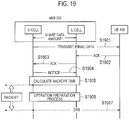
- a eNB 200 during a predetermined time period from the end of data transmission to a UE 100 in a second cell (U-Cell) to performing transmission of reference signal, stops transmission in the second cell and monitors interruption of other apparatuses in the specific frequency band.
- a communication control method in this embodiment includes: receiving, by the eNB 200, a reception acknowledgement signal from the UE 100 after a downlink data is transmitted through the second cell; stopping, by the eNB 200, the transmission of a downlink wireless signal containing the downlink data for a predetermined time period (backoff time) after the reception acknowledgement signal is received through the second cell; resuming, by the eNB 200, the transmission of the reference signal after the predetermined time period elapses; and setting, by the eNB 200, the predetermined time period at random or based on a usage condition of the second cell.
- Step S1901 the UE 100 receives the final downlink data through the U-Cell from the eNB 200.
- the eNB 200 continuously transmits the downlink data through the U-Cell exceeding 4 ms.
- 4 ms elapses after the downlink data is transmitted, the transmission is stopped once. Therefore, regarding the final downlink data in this step, it is noted that both the case of the final downlink data from the eNB 200 to the UE 100 and the case of stopping the transmission of the downlink data are included.
- Step S1902 the UE 100 transmits an acknowledgement signal (Ack) through the L-Cell to the eNB 200.
- Ack acknowledgement signal
- Step S1903 an L-Cell function unit of the eNB 200 receiving the acknowledgement signal of the final downlink data from the UE 100 transmits the acknowledgement signal of the final downlink data to the U-Cell function unit of the eNB 200.
- Step S1904 a U-Cell function unit of the eNB 200 notifies the reception of the acknowledgement signal to the L-Cell function unit of the eNB 200.
- Step S1905 the eNB 200 calculates a backoff time.
- the backoff time is a time during which the eNB 200 stops transmitting the downlink data or the reference signal through the U-Cell.
- Step S1906 the eNB 200 performs the operation preparation process for restarting the operation of the U-Cell during a period of the backoff time.
- Step S1907 the eNB 200 restarts the transmission of the DRS through the U-Cell after the backoff time elapses.
- the backoff time is a time provided for fairly sharing the unlicensed band with other apparatuses.
- the backoff time is a time for stopping the data transmission during a certain period until a certain apparatus retransmits data after the data transmission is ended.
- the backoff time may be selected at random, or may be determined based on a predetermined parameter (for example, a usage rate of a physical resource block (PRB) of the U-Cell).
- a predetermined parameter for example, a usage rate of a physical resource block (PRB) of the U-Cell.
- PRB physical resource block
- the eNB 200 monitors an interrupt of the other apparatus during the backoff time. In a case where there is an interrupt, even after the backoff time elapses, the eNB 200 determines that a predetermined bandwidth cannot be continuously used.
- the eNB 200 performs preparation for transmitting the downlink data after a burst time elapses. For example, the eNB 200 transmits an activation command of the component carrier through the L-Cell to the UE 100 which is scheduled to be allocated with the uplink resource on the U-Cell after the backoff time elapses.
- the application may be applied to a system different from the LTE system.
- LAA Licensed-Assisted Access
- LTE Carrier Aggregation UEs are not supposed to receive the broadcast system information on the Scell.
- LTE Physical Layer A straight forward way to enable licensed-assisted access to unlicensed spectrum is reusing the current LTE Physical Layer with extension and modifications to adapt various regulations in different countries or regions. Assuming this approach can keep the standardization effort to the minimum; however, it must ensure coexistence with the other already deployed unlicensed spectrum based technologies such as Wi-Fi.
- Another approach is to create a totally new LTE Physical Layer design (i.e., Further LTE Physical Layer Enhancements for unlicensed spectrum) with reusing the existing features as much as possible. This approach has a much better chance to get an effective LTE Physical Layer achieving a good harmonization with other unlicensed spectrum deployments. On the other hand, it may lose advantages of centrally-controlled system and may perform much worse than licensed LTE systems. Additionally, a brand new physical layer design could be very difficult to complete wthin Rel-13 time-frame. Therefore, it is proposed a LTE Physical Layer for unlicensed spectrum should be reuse the existing LTE Rel-12 design with extension to adapt regulations.
- a single global solution framework it is requested to determine a single global solution for LAA operation. Therefore, one unified LAA solution which can be meet the regulations for each country or region should be studied. Since the regulations of unlicensed spectrum are different in each country or region, it is required to design a system using the most stringent countries' and regions' regulations. e.g., Dynamic Frequency Selection (DFS), Transmit Power Control (TPC), Listen-Before-Talk (LBT) and burst transmission schemes must be considered to be incorporated to the existing physical layer design which enables LAA feature. It is necessary to further discuss if the above features are mandatory or optional.
- DFS Dynamic Frequency Selection
- TPC Transmit Power Control
- LBT Listen-Before-Talk
- burst transmission schemes must be considered to be incorporated to the existing physical layer design which enables LAA feature. It is necessary to further discuss if the above features are mandatory or optional.
- LAA should not impact Wi-Fi services.
- the fairness coexistence between different LAA operators and between LAA and other technologies in the same band is the design target as well.
- DFS, TPC, LBT and LTE burst transmission will be required in some countries or regions for using unlicensed spectrums. Almost all countries have requirements related to DFS and TPC for some bands. Although, these features are not supported in the existing releases it is necessary to introduce them to meet the above requirements. In addition, LBT and Burst transmission are required in Europe and Japan, which should be introduced as well.
- CC Comportment Carrier
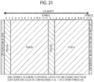
- 5 GHz spectrum is divided per 20 MHz bandwidth for use in Wi-Fi. It thinks CC in unlicensed spectrum should be aligned with this bandwidth for better coexistence. Note that the maximum number of aggregated CC should be 5 regardless the CC is in licensed spectrum or unlicensed spectrum. It means, if needed, up to 4 CCs in unlicensed spectrum should be aggregated at same time.
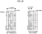
- Unlicensed spectrum should be used on an "on demand" basis. It's not a preferable situation that LTE use the unlicensed spectrum, but resource occupancy is quite low. (See the left figure of " Figure 20 ".) Therefore it should be specified the minimum resource occupancy rule in a CC in unlicensed spectrum. Also even though during ON duration in unlicensed band's CC, it should be good to create short idle periods for LTE transmission (e.g., LTE Burst) to enable Wi-Fi to interrupt on a same resources. In that case, it should be specified the minimum resource occupancy rule in a LTE Burst in unlicensed spectrum as well.
- LTE Burst LTE Burst
- PCI should not be allocated to neighbor cell. Within an operator's network, it can be achieved by cell planning or SON function. However, PCI collisions should be expected as the number of cells increases.
- multi-antenna transmission should be supported in unlicensed spectrum band. It is believed that beamforming based technologies can be effective by not causing unnecessary interference in unlicensed spectrum. To implement multi-antenna transmission technologies in unlicensed spectrum CSI information feedback should be considered.
- HARQ ACK/NACK transmission and corresponding retransmission should be modified if LTE Burst is applied. If unlicensed spectrum is used as UL transmission, it should be discussed if synchronous HARQ design can continue to be applied.
- Dynamic scheduling should be supported in unlicensed spectrum as same as in licensed spectrum. Both self-scheduling and cross carrier scheduling should be supported. If unlicensed spectrum is used on an "on demand" basis, some enhancement is needed for eNodeB to acquire necessary feedbacks from UE. Further study is needed if the existing PDCCH design is robust enough or not.
- LBT Similar to LBT (eNodeB).
- the LBT threshold values must be configurable by the network or the UE learns and adapts itself.
- TPC Further study is needed if any function should be standardized.
- LTE Burst length (Channel Occupancy time / Max Burst Length) This is needed to meet regulations in Europe and Japan. For achieving gap for LBT, LTE should be enhanced to support burst transmission. The Channel Occupancy time / Max Burst Length should be introduced. Note this is also helpful in coexistence with the Wi-Fi systems.
- LTE Beacon Broadcast channel
- Unlicensed spectrum usage information should be broadcasted for other operators. If DRS will be used for Synchronization in unlicensed spectrum, LTE Beacon can be transmitted along with the DRS.
- Resource allocation rule Further study is needed that a resource allocations rule should be standardized for achieving tight coordination when same CC sharing by more than one LAA services. [Table 4] Functionality Description Radio access Synchronization Reusing DRS as baseline. Further Study is needed for eNodeB behavior if LBT is applied and eNodeB detect higher interference than the threshold during LBT.
- Multi-antenna Transmission support and necessity feedbacks Further study is needed which transmission modes are supported in unlicensed spectrum and how eNodeB achieve feedbacks from UE if unlicensed spectrum is used on an "on demand” basis.
- HARQ protocols Further study is needed for HARQ design especially when unlicensed spectrum is used on an "on demand” basis.
- Scheduling and necessary feedbacks Further study is needed how eNodeB acquire necessary feedbacks for dynamic scheduling from UE if unlicensed spectrum is used on an "on demand” basis.
- Hopping In addition to support frequency hopping in the exiting specification, further study is needed if inter-CC Hopping is effective in unlicensed band operation when eNobeB can use more than 2 CC.
- Radio access UL transmission Timing adjustment PRACH may be introduced in unlicensed spectrum.
- UL transmission power control Further study is needed if it's enough to reuse the existing UL TPC mechanism.
- UL sounding Note there is no need to consider UL sounding if frequency domain dynamic scheduling is not supported in unlicensed spectrum.
- LAA Licensed-Assisted Access
- LTE Carrier Aggregation configurations and architecture where one or more low power Scell(s) operates in unlicensed spectrum and is either DL-only or contains both UL and DL and where the PCell operates in licensed spectrum and can be either LTE FDD or LTE TDD.
- the coverage area is quite different from the licensed carrier, e.g. Macro cell and RRH unlicensed cell, it's difficult to control the unlicensed carrier on such a large coverage area.
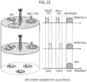
- licensed small cells should be used considering the fairness with WiFi. Therefore, it is assumed that the main scenario is that the LAA cells are co-located with small cells as shown in Figure 23 . It is proposed to reuse and modify the small cell enhancement (SCE) scenarios for LAA. For example, the frequency is changed from 3.5GHz into 5GHz.
- SCE small cell enhancement
- Proposal 1 The small cell enhancement (SCE) scenarios with minimum modifications should be reused for the LAA SI evaluations.
- Proposal 2 Scenario 2b for indoor deployment and Scenario 2a for outdoor deployment should be used for the LAA SI evaluations.
- the cell deployment from small cell scenarios for evaluating the impact on WiFi and unlicensed band is modified. It changes small cells into LAA cells and WiFi AP and categorize into 4 patterns. Table 7 is the proposed deployment scenario. Comparing the pattern A and pattern B, it can evaluate the impact of coexistence with WiFi. Comparing Pattern C or Pattern D, it can evaluate the impact of coexistence with different operators' LAA cells.
- Proposal 3 Deployment scenario for the LAA cells and WiFi APs are given in the table 7.
- Table 7 Scenario Outdoor Indoor (sparse) Indoor (dense) cells WiF iAP LAA cell (operat or A) LAA cell (operat or B) WiFi AP LAA cell (operat or A) LAA cell (operat or B) WiFi AP LAA cell (operat or A) LAA cell (operat or B) Pattern A 4 0 0 2 0 0 4 0 0 Pattern B 2 2 0 1 1 0 2 2 0 Pattern C 2 1 1 N/A N/A N/A 2 1 1 Pattern D 0 2 2 0 1 1 0 2 2
- the UE dropping scenario modifies the UE dropping scenario from small cell scenarios. It is proposed the total number of UEs per Wi-Fi cell and LAA cell is 10. Some of the UEs can connect to both the Wi-Fi and the LAA cells. It is proposed that the UE dropping as shown in Table 8.
- Proposal 4 It is proposed to use UE dropping scenario as given in the table 8.
- Table 8 LTE only UE WiFi only STA User terminal (Both LTE UE and WiFi STA) Pattern A - 40(10 for each AP) - Pattern B - - 20 (10 for each operator per cell) Pattern C - - 20 (10 for each operator per cell) Pattern D 40(10 for each operator per cell) - -
- LAA cell should not impact WiFi services (data, video and voice services) more than an additional WiFi network on the same carrier. It is consider that performance metrics for the estimation of the fairness between the LAA and the WiFi as shown in Table 9. [Table 9] Item description LTE User throughput (for each Operator) Full buffer traffic model; mean, 5%, and CDF of user throughput. LTE System throughput (for each Operator) WiFi User throughput Full buffer traffic model; mean, 5%, and CDF of user throughput. WiFi System throughput
- the impact on WiFi throughput is evaluated as follows using the above performance metrics.
- LTE-U achieves the fairness to the WiFi network.
- Proposal 5 Performance metrics to be used for measuring WiFi network fairness is given in the table 9.
Landscapes
- Engineering & Computer Science (AREA)
- Signal Processing (AREA)
- Computer Networks & Wireless Communication (AREA)
- Quality & Reliability (AREA)
- Databases & Information Systems (AREA)
- Computer Security & Cryptography (AREA)
- Mobile Radio Communication Systems (AREA)
Applications Claiming Priority (2)
| Application Number | Priority Date | Filing Date | Title |
|---|---|---|---|
| US201462056047P | 2014-09-26 | 2014-09-26 | |
| PCT/JP2015/076761 WO2016047628A1 (fr) | 2014-09-26 | 2015-09-18 | Station de base et station mobile |
Publications (2)
| Publication Number | Publication Date |
|---|---|
| EP3200510A1 true EP3200510A1 (fr) | 2017-08-02 |
| EP3200510A4 EP3200510A4 (fr) | 2018-06-27 |
Family
ID=55581153
Family Applications (1)
| Application Number | Title | Priority Date | Filing Date |
|---|---|---|---|
| EP15843460.5A Withdrawn EP3200510A4 (fr) | 2014-09-26 | 2015-09-18 | Station de base et station mobile |
Country Status (4)
| Country | Link |
|---|---|
| US (1) | US20170295576A1 (fr) |
| EP (1) | EP3200510A4 (fr) |
| JP (1) | JPWO2016047628A1 (fr) |
| WO (1) | WO2016047628A1 (fr) |
Families Citing this family (20)
| Publication number | Priority date | Publication date | Assignee | Title |
|---|---|---|---|---|
| US10075864B2 (en) * | 2014-07-02 | 2018-09-11 | Intel IP Corporation | System and method for measurement reporting in an unlicensed spectrum |
| US10925015B2 (en) * | 2014-10-29 | 2021-02-16 | Huawei Technologies Co., Ltd. | Method and apparatus for transmitting data frame in a long term evolution unlicensed (LTE-U)system |
| US10856224B2 (en) * | 2014-11-06 | 2020-12-01 | Samsung Electronics Co., Ltd. | Method and system for enabling discontinuous reception (DRX) over an unlicensed band in cellular networks |
| EP3228038B1 (fr) * | 2014-12-01 | 2023-01-25 | Sony Group Corporation | Protection de transmission |
| WO2017002251A1 (fr) * | 2015-07-01 | 2017-01-05 | 富士通株式会社 | Système de communication sans fil, terminal de communication, station de base et procédé de commande de cellule |
| WO2017061662A1 (fr) * | 2015-10-07 | 2017-04-13 | 엘지전자 주식회사 | Procédé et appareil pour émettre des données de réémission à l'aide d'une harq dans un système de communication sans fil |
| EP3198940B1 (fr) * | 2016-04-01 | 2020-06-03 | Telefonaktiebolaget LM Ericsson (publ) | Dispositif de réseau, dispositif terminal et procédés pour permettre le transfert intercellulaire de dispositif terminal |
| CN106102157B (zh) * | 2016-06-07 | 2019-10-15 | 北京佰才邦技术有限公司 | 一种发送同步信息的频率的选择方法和通信设备 |
| US10271227B2 (en) * | 2016-06-13 | 2019-04-23 | Qualcomm Incorporated | Enhanced neighbor relations and physical cell identifier confusion detection |
| US10517021B2 (en) | 2016-06-30 | 2019-12-24 | Evolve Cellular Inc. | Long term evolution-primary WiFi (LTE-PW) |
| US11350449B2 (en) * | 2016-09-29 | 2022-05-31 | Apple Inc. | Frequency hopping for unlicensed internet of things |
| US10477457B2 (en) * | 2016-11-03 | 2019-11-12 | Samsung Electronics Co., Ltd. | Apparatus and method to support ultra-wide bandwidth in fifth generation (5G) new radio |
| US11419083B2 (en) | 2016-11-08 | 2022-08-16 | Qualcomm Incorporated | Unified synchronization channel design used in different communication modes |
| US10531410B2 (en) * | 2016-11-08 | 2020-01-07 | Qualcomm Incorporated | Unified synchronization channel design used in different communication modes |
| US11044675B2 (en) * | 2018-02-13 | 2021-06-22 | Idac Holdings, Inc. | Methods, apparatuses and systems for adaptive uplink power control in a wireless network |
| AU2018416731A1 (en) * | 2018-03-30 | 2020-11-19 | Guangdong Oppo Mobile Telecommunications Corp., Ltd. | Information indication method and device, and computer storage medium |
| US11881924B2 (en) * | 2020-08-10 | 2024-01-23 | Qualcomm Incorporated | Beam selection for receiving channel state information reference signals for layer 3 measurement |
| CN116569628A (zh) * | 2021-01-06 | 2023-08-08 | 株式会社Ntt都科摩 | 终端、基站以及通信方法 |
| US20230034840A1 (en) * | 2021-07-30 | 2023-02-02 | Qualcomm Incorporated | Virtual component carriers |
| WO2024055137A1 (fr) * | 2022-09-12 | 2024-03-21 | Qualcomm Incorporated | Détection de commutation de signal de référence à travers des composants de porteuse |
Family Cites Families (8)
| Publication number | Priority date | Publication date | Assignee | Title |
|---|---|---|---|---|
| US8295243B2 (en) * | 2006-08-21 | 2012-10-23 | Qualcomm Incorporated | Method and apparatus for random access in an orthogonal multiple-access communication system |
| US8620334B2 (en) * | 2009-03-13 | 2013-12-31 | Interdigital Patent Holdings, Inc. | Method and apparatus for carrier assignment, configuration and switching for multicarrier wireless communications |
| US8670432B2 (en) * | 2009-06-22 | 2014-03-11 | Qualcomm Incorporated | Methods and apparatus for coordination of sending reference signals from multiple cells |
| WO2012135998A1 (fr) * | 2011-04-04 | 2012-10-11 | Renesas Mobile Corporation | Procédures d'accès aléatoire avec programmation inter porteuses |
| EP3589005B1 (fr) * | 2012-04-27 | 2022-05-11 | NEC Corporation | Terminal radio, station radio et procédés |
| JP2013236289A (ja) * | 2012-05-10 | 2013-11-21 | Sharp Corp | 端末、基地局、通信方法および集積回路 |
| EP3836648A1 (fr) * | 2012-08-23 | 2021-06-16 | Interdigital Patent Holdings, Inc. | Fournisseur de ressources de la couche physique vers different sites de service |
| WO2014113686A2 (fr) * | 2013-01-17 | 2014-07-24 | Interdigital Patent Holdings, Inc. | Placement de protocole de convergence de paquet de données (pdcp) |
-
2015
- 2015-09-18 JP JP2016550321A patent/JPWO2016047628A1/ja not_active Withdrawn
- 2015-09-18 US US15/512,739 patent/US20170295576A1/en not_active Abandoned
- 2015-09-18 EP EP15843460.5A patent/EP3200510A4/fr not_active Withdrawn
- 2015-09-18 WO PCT/JP2015/076761 patent/WO2016047628A1/fr active Application Filing
Also Published As
| Publication number | Publication date |
|---|---|
| EP3200510A4 (fr) | 2018-06-27 |
| JPWO2016047628A1 (ja) | 2017-07-20 |
| US20170295576A1 (en) | 2017-10-12 |
| WO2016047628A1 (fr) | 2016-03-31 |
Similar Documents
| Publication | Publication Date | Title |
|---|---|---|
| EP3200510A1 (fr) | Station de base et station mobile | |
| JP6901107B2 (ja) | 無線リソース構成同期 | |
| US11381361B2 (en) | Utilization information of a distributed unit for a configured grant in a wireless network | |
| US11950280B2 (en) | Channelization and BWP | |
| US10306637B2 (en) | Radio base station and user terminal | |
| CN107682936B (zh) | 用于适机联网的系统、方法和设备 | |
| JP6546185B2 (ja) | 基地局及びユーザ端末 | |
| KR101812751B1 (ko) | 비허가된 대역들을 통한 lte 채널 액세스 | |
| EP3149993B1 (fr) | Dispositifs et procédé permettant de récupérer et d'utiliser des informations de réseaux locaux sans fil voisins pour un fonctionnement lte laa | |
| US20170150427A1 (en) | Device, Network, and Method of Cell Discovery | |
| CN111801908A (zh) | 用于侧链路接口的多无线电接入技术调度的方法和装置 | |
| KR20170015251A (ko) | 비면허 대역 채널에서 클리어 채널 평가에 근거한 신호 전송 방법 및 이동 통신 시스템 | |
| KR20160147907A (ko) | 비주기적 비컨 및 기준 신호 송신을 위한 lte-u 통신 디바이스들 및 방법들 | |
| TW201642697A (zh) | 於主從裝置處之淨通道評估程序 | |
| EP3216136B1 (fr) | Équipement utilisateur et procédé permettant de communiquer sur des cellules conçues pour un accès assisté sous licence (laa) | |
| CN113039833A (zh) | 基于上行链路的前向移动性 | |
| CN115552987A (zh) | 用于用户设备(ue)间协调的车对万物(v2x)目的地标识共享 | |
| CN117980768A (zh) | 用于多雷达共存的波形参数和帧延迟协调 | |
| CN117981382A (zh) | 针对网络切片的数据收集增强 |
Legal Events
| Date | Code | Title | Description |
|---|---|---|---|
| PUAI | Public reference made under article 153(3) epc to a published international application that has entered the european phase |
Free format text: ORIGINAL CODE: 0009012 |
|
| 17P | Request for examination filed |
Effective date: 20170322 |
|
| AK | Designated contracting states |
Kind code of ref document: A1 Designated state(s): AL AT BE BG CH CY CZ DE DK EE ES FI FR GB GR HR HU IE IS IT LI LT LU LV MC MK MT NL NO PL PT RO RS SE SI SK SM TR |
|
| AX | Request for extension of the european patent |
Extension state: BA ME |
|
| DAV | Request for validation of the european patent (deleted) | ||
| DAX | Request for extension of the european patent (deleted) | ||
| RIC1 | Information provided on ipc code assigned before grant |
Ipc: H04W 72/04 20090101ALI20180215BHEP Ipc: H04W 88/10 20090101ALN20180215BHEP Ipc: H04W 74/00 20090101ALI20180215BHEP Ipc: H04W 72/08 20090101ALI20180215BHEP Ipc: H04W 48/12 20090101ALI20180215BHEP Ipc: H04W 88/06 20090101ALI20180215BHEP Ipc: H04W 48/18 20090101AFI20180215BHEP Ipc: H04W 74/08 20090101ALI20180215BHEP Ipc: H04W 52/14 20090101ALN20180215BHEP Ipc: H04L 5/00 20060101ALI20180215BHEP Ipc: H04W 56/00 20090101ALN20180215BHEP Ipc: H04W 16/14 20090101ALI20180215BHEP |
|
| A4 | Supplementary search report drawn up and despatched |
Effective date: 20180528 |
|
| RIC1 | Information provided on ipc code assigned before grant |
Ipc: H04W 72/04 20090101ALI20180522BHEP Ipc: H04W 48/18 20090101AFI20180522BHEP Ipc: H04W 16/14 20090101ALI20180522BHEP Ipc: H04W 74/08 20090101ALI20180522BHEP Ipc: H04W 52/14 20090101ALN20180522BHEP Ipc: H04W 88/10 20090101ALN20180522BHEP Ipc: H04W 72/08 20090101ALI20180522BHEP Ipc: H04W 88/06 20090101ALI20180522BHEP Ipc: H04W 48/12 20090101ALI20180522BHEP Ipc: H04W 74/00 20090101ALI20180522BHEP Ipc: H04L 5/00 20060101ALI20180522BHEP Ipc: H04W 56/00 20090101ALN20180522BHEP |
|
| STAA | Information on the status of an ep patent application or granted ep patent |
Free format text: STATUS: THE APPLICATION HAS BEEN WITHDRAWN |
|
| 18W | Application withdrawn |
Effective date: 20180816 |