EP3200412A1 - Procédé et dispositif mtc permettant de recevoir un canal de commande de liaison descendante - Google Patents
Procédé et dispositif mtc permettant de recevoir un canal de commande de liaison descendante Download PDFInfo
- Publication number
- EP3200412A1 EP3200412A1 EP15844009.9A EP15844009A EP3200412A1 EP 3200412 A1 EP3200412 A1 EP 3200412A1 EP 15844009 A EP15844009 A EP 15844009A EP 3200412 A1 EP3200412 A1 EP 3200412A1
- Authority
- EP
- European Patent Office
- Prior art keywords
- epdcch
- transmitted
- crs
- index
- transmission
- Prior art date
- Legal status (The legal status is an assumption and is not a legal conclusion. Google has not performed a legal analysis and makes no representation as to the accuracy of the status listed.)
- Granted
Links
- 238000000034 method Methods 0.000 title claims abstract description 68
- 239000011159 matrix material Substances 0.000 claims abstract description 58
- 238000004891 communication Methods 0.000 claims abstract description 30
- 230000005540 biological transmission Effects 0.000 claims description 185
- 238000013507 mapping Methods 0.000 description 92
- 101001056707 Homo sapiens Proepiregulin Proteins 0.000 description 75
- 102100025498 Proepiregulin Human genes 0.000 description 75
- 238000012544 monitoring process Methods 0.000 description 12
- 108010003272 Hyaluronate lyase Proteins 0.000 description 8
- 230000002776 aggregation Effects 0.000 description 8
- 238000004220 aggregation Methods 0.000 description 8
- 239000000969 carrier Substances 0.000 description 8
- 230000004044 response Effects 0.000 description 6
- 230000011664 signaling Effects 0.000 description 6
- 238000013468 resource allocation Methods 0.000 description 5
- 230000007480 spreading Effects 0.000 description 5
- 230000006870 function Effects 0.000 description 4
- 230000007774 longterm Effects 0.000 description 4
- 230000008569 process Effects 0.000 description 4
- 230000009467 reduction Effects 0.000 description 3
- 230000001174 ascending effect Effects 0.000 description 2
- 230000008859 change Effects 0.000 description 2
- 238000010586 diagram Methods 0.000 description 2
- 230000003993 interaction Effects 0.000 description 2
- 239000002699 waste material Substances 0.000 description 2
- 101000741965 Homo sapiens Inactive tyrosine-protein kinase PRAG1 Proteins 0.000 description 1
- 102100038659 Inactive tyrosine-protein kinase PRAG1 Human genes 0.000 description 1
- 230000001413 cellular effect Effects 0.000 description 1
- 125000004122 cyclic group Chemical group 0.000 description 1
- 238000010295 mobile communication Methods 0.000 description 1
- 238000012986 modification Methods 0.000 description 1
- 230000004048 modification Effects 0.000 description 1
- 238000012545 processing Methods 0.000 description 1
- 230000003252 repetitive effect Effects 0.000 description 1
- 238000011160 research Methods 0.000 description 1
- XLYOFNOQVPJJNP-UHFFFAOYSA-N water Substances O XLYOFNOQVPJJNP-UHFFFAOYSA-N 0.000 description 1
Images


Classifications
-
- H—ELECTRICITY
- H04—ELECTRIC COMMUNICATION TECHNIQUE
- H04W—WIRELESS COMMUNICATION NETWORKS
- H04W72/00—Local resource management
- H04W72/20—Control channels or signalling for resource management
- H04W72/23—Control channels or signalling for resource management in the downlink direction of a wireless link, i.e. towards a terminal
-
- H—ELECTRICITY
- H04—ELECTRIC COMMUNICATION TECHNIQUE
- H04L—TRANSMISSION OF DIGITAL INFORMATION, e.g. TELEGRAPHIC COMMUNICATION
- H04L5/00—Arrangements affording multiple use of the transmission path
- H04L5/003—Arrangements for allocating sub-channels of the transmission path
- H04L5/0053—Allocation of signaling, i.e. of overhead other than pilot signals
-
- H—ELECTRICITY
- H04—ELECTRIC COMMUNICATION TECHNIQUE
- H04B—TRANSMISSION
- H04B7/00—Radio transmission systems, i.e. using radiation field
- H04B7/02—Diversity systems; Multi-antenna system, i.e. transmission or reception using multiple antennas
- H04B7/04—Diversity systems; Multi-antenna system, i.e. transmission or reception using multiple antennas using two or more spaced independent antennas
- H04B7/0413—MIMO systems
- H04B7/0456—Selection of precoding matrices or codebooks, e.g. using matrices antenna weighting
-
- H—ELECTRICITY
- H04—ELECTRIC COMMUNICATION TECHNIQUE
- H04B—TRANSMISSION
- H04B7/00—Radio transmission systems, i.e. using radiation field
- H04B7/02—Diversity systems; Multi-antenna system, i.e. transmission or reception using multiple antennas
- H04B7/04—Diversity systems; Multi-antenna system, i.e. transmission or reception using multiple antennas using two or more spaced independent antennas
- H04B7/06—Diversity systems; Multi-antenna system, i.e. transmission or reception using multiple antennas using two or more spaced independent antennas at the transmitting station
- H04B7/0613—Diversity systems; Multi-antenna system, i.e. transmission or reception using multiple antennas using two or more spaced independent antennas at the transmitting station using simultaneous transmission
- H04B7/0615—Diversity systems; Multi-antenna system, i.e. transmission or reception using multiple antennas using two or more spaced independent antennas at the transmitting station using simultaneous transmission of weighted versions of same signal
- H04B7/0619—Diversity systems; Multi-antenna system, i.e. transmission or reception using multiple antennas using two or more spaced independent antennas at the transmitting station using simultaneous transmission of weighted versions of same signal using feedback from receiving side
- H04B7/0621—Feedback content
- H04B7/0632—Channel quality parameters, e.g. channel quality indicator [CQI]
-
- H—ELECTRICITY
- H04—ELECTRIC COMMUNICATION TECHNIQUE
- H04L—TRANSMISSION OF DIGITAL INFORMATION, e.g. TELEGRAPHIC COMMUNICATION
- H04L25/00—Baseband systems
- H04L25/02—Details ; arrangements for supplying electrical power along data transmission lines
- H04L25/03—Shaping networks in transmitter or receiver, e.g. adaptive shaping networks
- H04L25/03891—Spatial equalizers
- H04L25/03898—Spatial equalizers codebook-based design
-
- H—ELECTRICITY
- H04—ELECTRIC COMMUNICATION TECHNIQUE
- H04L—TRANSMISSION OF DIGITAL INFORMATION, e.g. TELEGRAPHIC COMMUNICATION
- H04L5/00—Arrangements affording multiple use of the transmission path
- H04L5/003—Arrangements for allocating sub-channels of the transmission path
- H04L5/0048—Allocation of pilot signals, i.e. of signals known to the receiver
- H04L5/005—Allocation of pilot signals, i.e. of signals known to the receiver of common pilots, i.e. pilots destined for multiple users or terminals
-
- H—ELECTRICITY
- H04—ELECTRIC COMMUNICATION TECHNIQUE
- H04L—TRANSMISSION OF DIGITAL INFORMATION, e.g. TELEGRAPHIC COMMUNICATION
- H04L5/00—Arrangements affording multiple use of the transmission path
- H04L5/0091—Signaling for the administration of the divided path
- H04L5/0094—Indication of how sub-channels of the path are allocated
-
- H—ELECTRICITY
- H04—ELECTRIC COMMUNICATION TECHNIQUE
- H04W—WIRELESS COMMUNICATION NETWORKS
- H04W72/00—Local resource management
- H04W72/04—Wireless resource allocation
- H04W72/044—Wireless resource allocation based on the type of the allocated resource
- H04W72/0446—Resources in time domain, e.g. slots or frames
-
- H—ELECTRICITY
- H04—ELECTRIC COMMUNICATION TECHNIQUE
- H04W—WIRELESS COMMUNICATION NETWORKS
- H04W72/00—Local resource management
- H04W72/12—Wireless traffic scheduling
-
- H—ELECTRICITY
- H04—ELECTRIC COMMUNICATION TECHNIQUE
- H04L—TRANSMISSION OF DIGITAL INFORMATION, e.g. TELEGRAPHIC COMMUNICATION
- H04L5/00—Arrangements affording multiple use of the transmission path
- H04L5/0001—Arrangements for dividing the transmission path
- H04L5/0014—Three-dimensional division
- H04L5/0023—Time-frequency-space
-
- H—ELECTRICITY
- H04—ELECTRIC COMMUNICATION TECHNIQUE
- H04W—WIRELESS COMMUNICATION NETWORKS
- H04W4/00—Services specially adapted for wireless communication networks; Facilities therefor
- H04W4/70—Services for machine-to-machine communication [M2M] or machine type communication [MTC]
-
- H—ELECTRICITY
- H04—ELECTRIC COMMUNICATION TECHNIQUE
- H04W—WIRELESS COMMUNICATION NETWORKS
- H04W84/00—Network topologies
- H04W84/02—Hierarchically pre-organised networks, e.g. paging networks, cellular networks, WLAN [Wireless Local Area Network] or WLL [Wireless Local Loop]
- H04W84/04—Large scale networks; Deep hierarchical networks
- H04W84/042—Public Land Mobile systems, e.g. cellular systems
Definitions
- the present invention relates to mobile communication.
- 3GPP (3rd Generation Partnership Project) LTE Long Term Evolution (Long Term Evolution) that is an advancement of UMTS (Universal Mobile Telecommunication System) is being introduced with 3GPP release 8.
- 3GPP LTE OFDMA (orthogonal frequency division multiple access) is used for downlink, and SC-FDMA (single carrier-frequency division multiple access) is used for uplink.
- the 3GPP LTE adopts MIMO (multiple input multiple output) having maximum four antennas.
- 3GPP LTE-A LTE-Advanced
- the physical channels in 3GPP LTE may be classified into data channels such as PDSCH (physical downlink shared channel) and PUSCH (physical uplink shared channel) and control channels such as PDCCH (physical downlink control channel), PCFICH (physical control format indicator channel), PHICH (physical hybrid-ARQ indicator channel) and PUCCH (physical uplink control channel).
- data channels such as PDSCH (physical downlink shared channel) and PUSCH (physical uplink shared channel)
- control channels such as PDCCH (physical downlink control channel), PCFICH (physical control format indicator channel), PHICH (physical hybrid-ARQ indicator channel) and PUCCH (physical uplink control channel).
- MTC machine type communication
- UE user equipment
- a service optimized to the MTC may differ from a service optimized to human-to-human communication.
- the MTC can be characterized as a different market scenario, data communication, less costs and efforts, a potentially great number of MTC apparatuses, wide service areas, low traffic for each MTC apparatus, etc.
- the MTC device may use only a reduced band, regardless of a system bandwidth of a cell.
- the present disclosure newly proposes a downlink control channel transmittable in a band in which an MTC device operates.
- an embodiment of the present disclosure provides a method for receiving a downlink control channel in a machine type communication (MTC) device configured to operate only in a partial band of a system band of a cell.
- the method for receiving a downlink control channel may include: determining a precoding matrix index (PMI) applied to a downlink control channel receivable only in the partial band; receiving the downlink control channel in the partial band in a data region of a subframe from the cell; and decoding the downlink control channel, which has been received from the cell, on the basis of the determined PMI.
- PMI precoding matrix index
- the partial band may correspond to six physical resource blocks (PRBs) of the system band.
- PRBs physical resource blocks
- the method may further include: receiving information regarding the PMI in the case of localized transmission in which the downlink control channel is mapped only to partial PRBs, wherein the determination of the PMI may be performed on the basis of the received information regarding the PMI.
- the PMI may be determined on the basis of any one of an index of the partial band, an index of the PRB, an index of a transmission antenna port transmitting the downlink control channel, and an index of the sub frame.
- a pattern of the PMI regarding the downlink control channel may be determined.
- the method may further include: receiving information regarding the PMI determined by the cell on the basis of any one of an index of the partial band, an index of the PRB, an index of a transmission antenna port transmitting the downlink control channel, and an index of the subframe in the case of distributed transmission in which the downlink control channel is mapped to multiple PRBs.
- an embodiment of the present disclosure provides a machine type communication (MTC) device configured to operate only in a partial band of a system band of a cell.
- the MTC device may include: a processor determining a precoding matrix index (PMI) applied to a downlink control channel receivable only in the partial band; and a reception unit receiving the downlink control channel in the partial band in a data region of a subframe from the cell, wherein the processor decodes the downlink control channel, which has been received from the cell, on the basis of the determined PMI.
- PMI precoding matrix index
- LTE long term evolution
- LTE-A 3rd Generation Partnership Project LTE-advanced
- the term 'include' or 'have' may represent the existence of a feature, a number, a step, an operation, a component, a part or the combination thereof described in the specification, and may not exclude the existence or addition of another feature, another number, another step, another operation, another component, another part or the combination thereof.
- first' and 'second' are used for the purpose of explanation about various components, and the components are not limited to the terms 'first' and 'second'.
- the terms 'first' and 'second' are only used to distinguish one component from another component.
- a first component may be named as a second component without deviating from the scope of the present invention.
- 'base station' generally refers to a fixed station that communicates with a wireless device and may be denoted by other terms such as eNB (evolved-NodeB), BTS (base transceiver system), or access point.
- eNB evolved-NodeB
- BTS base transceiver system
- UE user equipment
- UE may be stationary or mobile, and may be denoted by other terms such as device, wireless device, terminal, MS(mobile station), UT(user terminal), SS(subscriber station), MT(mobile terminal) and etc.
- FIG. 1 illustrates a wireless communication system
- the wireless communication system includes at least one base station (BS) 20.
- Each base station 20 provides a communication service to specific geographical areas (generally, referred to as cells) 20a, 20b, and 20c.
- the cell can be further divided into a plurality of areas (sectors).
- the UE generally belongs to one cell and the cell to which the terminal belong is referred to as a serving cell.
- a base station that provides the communication service to the serving cell is referred to as a serving BS. Since the wireless communication system is a cellular system, another cell that neighbors to the serving cell is present. Another cell which neighbors to the serving cell is referred to a neighbor cell.
- a base station that provides the communication service to the neighbor cell is referred to as a neighbor BS.
- the serving cell and the neighbor cell are relatively decided based on the UE.
- a downlink means communication from the base station 20 to the UE1 10 and an uplink means communication from the UE 10 to the base station 20.
- a transmitter may be a part of the base station 20 and a receiver may be a part of the UE 10.
- the transmitter may be a part of the UE 10 and the receiver may be a part of the base station 20.
- the wireless communication system may be generally divided into a frequency division duplex (FDD) type and a time division duplex (TDD) type.
- FDD frequency division duplex
- TDD time division duplex
- uplink transmission and downlink transmission are achieved while occupying different frequency bands.
- the uplink transmission and the downlink transmission are achieved at different time while occupying the same frequency band.
- a channel response of the TDD type is substantially reciprocal. This means that a downlink channel response and an uplink channel response are approximately the same as each other in a given frequency area. Accordingly, in the TDD based wireless communication system, the downlink channel response may be acquired from the uplink channel response.
- the downlink transmission by the base station and the uplink transmission by the terminal may not be performed simultaneously.
- the uplink transmission and the downlink transmission are performed in different sub-frames.
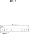
- FIG. 2 shows a downlink radio frame structure according to FDD of 3rd generation partnership project (3GPP) long term evolution (LTE).
- 3GPP 3rd generation partnership project
- LTE long term evolution
- the radio frame of FIG. 2 may be found in the section 5 of 3GPP TS 36.211 V10.4.0 (2011-12) "Evolved Universal Terrestrial Radio Access (E-UTRA); Physical Channels and Modulation (Release 10)".
- the radio frame consists of 10 subframes.
- One subframe consists of two slots. Slots included in the radio frame are numbered with slot numbers 0 to 19.
- a time required to transmit one subframe is defined as a transmission time interval (TTI).
- TTI may be a scheduling unit for data transmission.
- one radio frame may have a length of 10 milliseconds (ms)
- one subframe may have a length of 1 ms
- one slot may have a length of 0.5 ms.
- the structure of the radio frame is for exemplary purposes only, and thus the number of subframes included in the radio frame or the number of slots included in the subframe may change variously.
- one slot may include a plurality of orthogonal frequency division multiplexing (OFDM) symbols.
- the number of OFDM symbols included in one slot may vary depending on a cyclic prefix (CP).
- One slot includes 7 OFDM symbols in case of a normal CP, and one slot includes 6 OFDM symbols in case of an extended CP.
- OFDM symbols since the 3GPP LTE uses orthogonal frequency division multiple access (OFDMA) in a downlink (DL), the OFDM symbol is only for expressing one symbol period in a time domain, and there is no limitation in a multiple access scheme or terminologies.
- the OFDM symbol may also be referred to as another terminology such as a single carrier frequency division multiple access (SC-FDMA) symbol, a symbol period, etc.
- SC-FDMA single carrier frequency division multiple access
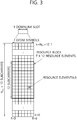
- FIG. 3 illustrates an example resource grid for one uplink or downlink slot in 3GPP LTE.
- the uplink slot includes a plurality of OFDM (orthogonal frequency division multiplexing) symbols in the time domain and NRB resource blocks (RBs) in the frequency domain.
- RBs resource blocks
- the number of resource blocks (RBs), i.e., N RB maybe one from 6 to 110.
- Resource block is a resource allocation unit and includes a plurality of sub-carriers in one slot. For example, if one slot includes seven OFDM symbols in the time domain and the resource block includes 12 sub-carriers in the frequency domain, one resource block may include 7x12 resource elements (REs).
- REs resource elements
- the number of sub-carriers in one OFDM symbol may be one of 128, 256, 512, 1024, 1536, and 2048.
- the resource grid for one uplink slot shown in FIG. 3 may also apply to the resource grid for the downlink slot.
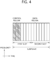
- FIG. 4 illustrates the architecture of a downlink sub-frame.
- one slot includes seven OFDM symbols, by way of example.
- the DL (downlink) sub-frame is split into a control region and a data region in the time domain.
- the control region includes up to first three OFDM symbols in the first slot of the sub-frame. However, the number of OFDM symbols included in the control region may be changed.
- a PDCCH (physical downlink control channel) and other control channels are allocated to the control region, and a PDSCH is allocated to the data region.
- the physical channels in 3GPP LTE may be classified into data channels such as PDSCH (physical downlink shared channel) and PUSCH (physical uplink shared channel) and control channels such as PDCCH (physical downlink control channel), PCFICH (physical control format indicator channel), PHICH (physical hybrid-ARQ indicator channel) and PUCCH (physical uplink control channel).
- data channels such as PDSCH (physical downlink shared channel) and PUSCH (physical uplink shared channel) and control channels
- PDCCH physical downlink control channel
- PCFICH physical control format indicator channel
- PHICH physical hybrid-ARQ indicator channel
- PUCCH physical uplink control channel
- FIG. 5 illustrates the architecture of an uplink sub-frame in 3GPP LTE.
- the uplink sub-frame may be separated into a control region and a data region in the frequency domain.
- the control region is assigned a PUCCH (physical uplink control channel) for transmission of uplink control information.
- the data region is assigned a PUSCH (physical uplink shared channel) for transmission of data (in some cases, control information may also be transmitted).
- the PUCCH for one terminal is assigned in resource block (RB) pair in the sub-frame.
- the resource blocks in the resource block pair take up different sub-carriers in each of the first and second slots.
- the frequency occupied by the resource blocks in the resource block pair assigned to the PUCCH is varied with respect to a slot boundary. This is referred to as the RB pair assigned to the PUCCH having been frequency-hopped at the slot boundary.
- the terminal may obtain a frequency diversity gain by transmitting uplink control information through different sub-carriers over time.
- m is a location index that indicates a logical frequency domain location of a resource block pair assigned to the PUCCH in the sub-frame.
- the uplink control information transmitted on the PUCCH includes an HARQ (hybrid automatic repeat request), an ACK (acknowledgement)/NACK (non-acknowledgement), a CQI (channel quality indicator) indicating a downlink channel state, and an SR (scheduling request) that is an uplink radio resource allocation request.
- HARQ hybrid automatic repeat request
- ACK acknowledgenowledgement
- NACK non-acknowledgement
- CQI channel quality indicator
- SR scheduling request
- the PUSCH is mapped with a UL-SCH that is a transport channel.
- the uplink data transmitted on the PUSCH may be a transport block that is a data block for the UL-SCH transmitted for the TTI.
- the transport block may be user information.
- the uplink data may be multiplexed data.
- the multiplexed data may be data obtained by multiplexing the transport block for the UL-SCH and control information.
- the control information multiplexed with the data may include a CQI, a PMI (precoding matrix indicator), an HARQ, and an RI (rank indicator).
- the uplink data may consist only of control information.
- a reference signal (RS) is hereinafter described.
- transmission information i.e., data
- a reference signal is needed to demodulate the transmission information without an error.
- the reference signal is a signal well known between a transmitter and a receiver, and transmitted along with transmission information. Transmission information transmitted by the transmitter goes through various channels corresponding to transmission antennas or layers, and therefore, the reference signal may be allocated to each transmission antenna or layer. A reference signal for each transmission antenna or layer may be distinguishable using a resource such as time, frequency, or code. The reference signal may be used .for two purposes: demodulation of transmission information and channel estimation.
- a downlink reference signal may be classified as a cell-specific RS (CRS), MBMS over a Single Frequency Network (MBSFN) RS, a UE-specific RS (URS), a positioning RS (PRS), or a CSI-RS.
- CRS is an RS transmitted to every UE in a cell, and may be referred to as a common reference signal.
- the CRS may be used for channel estimation in response to a CQI feedback and channel estimation for a PDSCH.
- the MBSFN RS may be transmitted to a subframe allocated to transmit a MBSFN.
- the URS is a reference signal received by a specific UE or a specific UE group in a cell, and may be referred to as a demodulation RS (DM-RS).
- the DM-RS is primarily used for data demodulation by a specific UE or a specific UE group.
- the PRS may be used for estimation of a location of an UE.
- the CSI-RS is used for estimation of a channel for a PDSCH of an LTE-A UE.
- the CSI-RS is sparsely arranged in frequency domain or time domain, and may be punctured in a data region of a normal subframe or an MBSFN subframe.
- FIG. 6 shows an exemplary pattern in which a CRS is mapped to an RB in a case where a base station uses a single antenna port.
- R0 indicates an RE onto which a CRS transmitted by antenna port 0 of the base station is mapped.
- a CRS is transmitted by every downlink subframe in a cell that supports transmission of a PDSCH.
- the CRS may be transmitted over antenna port 0 or antenna port 3.
- An RE allocated to a CRS of a single antenna port is not able to be used for transmission of a different antenna port, and should be set as zero.
- a CRS is transmitted in a non MBSFN region.
- CA carrier aggregation
- the CA system refers to aggregate a plurality of component carriers (CCs). Due to CA, the meaning of a legacy cell has been changed. According to CA, a cell may refer to a combination of a downlink (DL) CC and an uplink (UL) CC or a single DL CC.
- DL downlink
- UL uplink
- a cell may be classified as a primary cell, a secondary cell, and a serving cell.
- the primary cell refers to a cell operating in a primary frequency and refers to a cell in which a UE performs an initial connection establishment procedure or a connection re-establishment procedure with a BS (or an eNB) or a cell indicated as a primary cell during a handover procedure.
- the secondary cell refers to a cell operating in a secondary frequency, which is configured once RRC connection is established and which is used to provide additional wireless resource.
- a plurality of CCs i.e., a plurality of serving cells, may be supported, unlike a single carrier system.
- Such carrier aggregation system may support cross-carrier scheduling.
- the cross-carrier scheduling is a scheduling scheme that may conduct resource allocation of a PUSCH transmitted through other component carriers than the component carrier basically linked to a specific component carrier and/or resource allocation of a PDSCH transmitted through other component carriers through a PDCCH transmitted through the specific component carrier.
- a PDCCH is monitored in a limited area called a control area within a subframe, and a CRS transmitted in the entire band is used to demodulate the PDCCH.
- types of control information is varied and an amount of control information is increased, flexibility of scheduling is lowered only by the legacy PDCCH.
- an enhanced PDCCH (EPDCCH) has been introduced.
- FIG. 7 illustrates an example of a subframe having an EPDCCH.
- a subframe may include zero or one PDCCH region 410 and zero or more EPDCCH regions 420 and 430.
- the EPDCCH regions 420 and 430 are regions in which a wireless device monitors an EPDCCH.
- the PDCCH region 410 is positioned within a maximum of four front OFDM symbols of the subframe, while the EPDCCH regions 420 and 430 may be flexibly scheduled in OFDM symbols after the PDCCH region 410.
- One or more EPDCCH regions 420 and 430 are designated in a wireless device, and the wireless device may monitor an EPDCCH in the designated EPDCCH regions 420 and 430.
- the number/position/size of the EPDCCH regions 420 and 430 and/or information regarding a subframe for monitoring the EPDCCH may be provided by a BS to the wireless device through an RRC message, or the like.
- a PDCCH may be demodulated on the basis of a CRS.
- a demodulation (DM) RS not the CRS, may be defined to demodulate the EPDCCH.
- An associated DM RS may be transmitted in the corresponding EPDCCH regions 420 and 430.
- the EPDCCH regions 420 and 430 may each be used in scheduling for different cells.
- an EPDCCH within the EPDCCH region 420 may carry scheduling information for a primary cell
- an EPDCCH within the EPDCCH region 430 may carry scheduling information for a secondary cell.
- the same precoding as that of the EPDCCH may be applied to a DMRS within the EPDCCH regions 420 and 430.
- an EPDCCH search space may correspond to an EPDCCH region.
- one or more EPDCCH candidates may be monitored at every one or more aggregation levels.
- An EPDCCH is transmitted using one or more ECCEs.
- An ECCE includes a plurality of enhanced resource element groups (EREGs).
- An ECCE may include 4 EGEGs or 8 EREGs according to a subframe type and a CP according to time division duplex (TDD) DL-UL configuration.
- TDD time division duplex
- an ECCE may include four EREGs, and in an extended CP, an ECCE may include eight EREGs.
- a physical resource block (PRB) pair refers to two PRBs having the same RB number in a subframe.
- a PRB pair refers to a first PRB of a first slot and a second PRB of a second slot in the same frequency region.
- a PRB pair includes 12 subcarriers and 14 OFDM symbols, and thus, it includes 168 resource elements (REs).
- An EPDCCH search space may be configured by one or a plurality of PRB pairs.
- One PRB pair includes 16 EREGs.
- the PRB pair includes 4 ECCEs
- the PRB pair includes 8 EREGs
- the PRB pair includes two ECCEs.
- FIG. 8 illustrates an example of a PRB pair structure.
- a PRB group includes four PRB pairs but the number is not limited.
- FIG. 8 illustrates an EREG set when an ECCE includes 4 EREGs.
- (B) of FIG. 8 includes an EREG set when an ECCE includes 8 EREGs.
- an ECCE includes 4 EREGs, unless otherwise mentioned.
- An EPDCCH supports localized transmission and distributed transmission.
- EREGs forming one ECCE are transmitted in one PRB pair.
- EREGs forming one ECCE are transmitted in a plurality of PRB pairs.
- FIG. 9 illustrates an example of localized transmission and distributed transmission.
- FIG. 9 illustrates an example of ECCE-to-EREG mapping according to localized transmission.
- a localized ECCE refers to an ECCE used in localized transmission.
- B) of FIG. 9 illustrates an example of ECCE-to-EREG mapping according to distributed transmission.
- a distributed ECCE refers to an ECCE used in configuring a distributed ECCE.
- An EREG aggregate refers to an aggregate of EREGs used to form a located ECCE or a distributed ECCE. That is, an ECCE may include EREGs that belong to the same EREG aggregate.
- an EPDCCH is demodulated on the basis of a DMRS.
- FIG. 10 illustrates an example of RE mapping for a DM RS.
- the DM RS may perform channel estimation by a method according to a value of a spreading factor K.
- FIG. 10 illustrates RE mapping in a regular CP.
- RE mapping may be expressed by Equation 1 below.
- a k , l p w p l ⁇ ⁇ r 3 ⁇ l ⁇ ⁇ N RB max , DL + 3 ⁇ n PRB + m ⁇
- the wireless device when antenna port p is p ⁇ 107, 108, 109, 110 ⁇ , the wireless device recognizes that the spreading factor is 4, and when antenna port p is p ⁇ 107, 108 ⁇ , the wireless device recognizes that the spreading factor is 2.
- K 4
- a channel estimation process is varied according to spreading factors.
- FIGS. 11A and 11B illustrate a way in which REs are included in one EREG of an EPDCCH.
- REs included in one EREG of the EPDCCH are indicated by the same numbers. For example, 9 REs indicated by 0 are included in one EREG as illustrated in FIG. 11B .
- RE mapping of EREG RE resource in which a DMRS is transmitted is excluded.
- FIG. 12A illustrates an example of MTC.
- MTC refers to information exchange between MTC devices 100 through a BS 200 without human interaction or information exchange between the MTC device 100 and an MTC server 700 through a BS.
- the MTC server 700 is an entity communicating with the MTC device 100.
- the MTC server 700 executes an MTC application and provides an MTC-specific service to the MTC device.
- the MTC device 100 is a wireless device providing MTC communication, which may be fixed or mobile.
- a service provided through MTC is different from a legacy service of communication in which a person intervenes, and various categories of service such as tracking, metering, payment, a medical field service, remote controlling, and the like, are provided.
- a service provided through MTC may include reading a meter, measuring a water level, utilization of a monitoring camera, report of an inventory of a vending machine, and the like.
- the MTC device has characteristics in that a transmission data amount is small and transmission/reception of uplink/downlink data occurs occasionally, it is effective to reduce cost and battery consumption of the MTC device according to a low data rate.
- the MTC device has small mobility, having characteristics that a channel environment rarely changes.
- FIG. 12B illustrates extending of cell coverage for an MTC device.
- FIGS. 13A and 13B are views illustrating examples of sub-bands in which an MTC device operates.
- the MTC device may use a sub-band of about 1.4 MHz, for example, regardless of system bandwidth of a cell as illustrated in FIG. 13A .
- a region of the sub-band in which the MTC device operates may be positioned in a central region (e.g., six central PRBs) of a system bandwidth of a cell as illustrated in FIG. 13A .
- sub-bands of the MTC device may be placed in a single frame for multiplexing within a subframe between MTC devices so that the MTC devices may use different sub-bands or may use the same sub-band but use different sub-bands not in the six central PRB regions.
- the MTC device may not properly receive a legacy PDCCH transmitted in the entire system band. Also, it may not be desirable for a PDCCH for an MTC device to be transmitted in an OFDM symbol region in which a legacy PDCCH is transmitted due to a multiplexing issue with the PDCCH transmitted to a different MTC device.
- an embodiment of the present disclosure provides a method for solving such a problem.
- an embodiment of the present disclosure proposes an introduction of a separate control channel for an MTC device within a sub-band in which the MTC device operates, as a method for solving the aforementioned problem.
- N-PDCCH new EPDCCH
- M-PDCCH MTC-dedicated EPDCCH
- the N-EPDCCH (or the M-EPDCCH) may use a configuration of the legacy EPDCCH as is. Or, the N-EPDCCH (or M-EPDCCH) may have a modified configuration of a legacy EPDCCH. However, the N-EPDCCH may basically follow all the characteristics of the legacy EPDCCH as is.
- the N-EPDCCH is used for an MTC device, but the present disclosure may also be applied to a case in which the N-EPDCCH is used for a general UE, rather than the MTC device.
- Channel estimation may be performed on the basis of a DMRS as in the legacy EPDCCH in order to demodulate the N-EPDCCH (or M-EPDCCH) proposed in the present disclosure, or performing channel estimation on the basis of a CRS as in the legacy PDCCH may also be taken into consideration. It may not be desirable for an MTC device to have both capability of performing CRS-based channel estimation and capability of performing DMRS-based channel estimation in terms of cost reduction of the MTC device.
- only CRS-based channel estimation may be supported.
- the N-EPDCCH may be configured as follows.
- an N-EPDCCH (or M-EPDCCH) demodulated using CRS-based channel estimation is termed a CRS-based N-EPDCCH (or M-EPDCCH).
- an N-EPDCCH (or M-EPDCCH) using DMRS-based channel estimation will be referred to as a DMRS-based N-EPDCCH (or M-EPDCCH).
- an N-EPDCCH (or M-EPDCCH) using both CRS and DMRS will be referred to as a CRS and/or DMRS-based N-EPDCCH (or M-EPDCCH).
- the EDPCCH should be transmitted using an antenna port used by a CRS. That is, the N-EPDCCH (or M-EPDCCH) may be transmitted through the entirety or a portion of antenna ports 0, 1, 2, and 3.
- an MTC device may be able always to expect a CRS in a subframe in which the N-EPDCCH (or M-EPDCCH) is transmitted.
- an EREG to RE mapping scheme designed in consideration of only a current DMRS may be changed to a mapping scheme considering a CRS.
- An example of such a new EREG-to-RE mapping is mentioned in Paragraph III.
- the N-EPDCCH may be transmitted in a transmit diversity scheme in which an EPDCCH can be received although the MTC device does not know the precoding matrix.
- the CRS-based N-EPDCCH may be transmitted through an SFBC technique. A method for applying such an SFBC and contents regarding an antenna port configuration are mentioned in Paragraph IV of the present disclosure.
- the N-EPDCCH may be transmitted using the entirety or a portion of antenna ports 0, 1, 2, and 3.
- the MTC device should be able to always expect a CRS in a subframe in which the N-EPDCCH (or M-EPDCCH) is received.
- a CRS or a reference signal (RS) having the same structure as that of the CRS should be received.
- RS reference signal
- such an RS should be transmitted in a partial narrow band of the entire system band of a cell.
- such an RS will be termed a narrow-CRS (CRS transmitted only in a specific PRB).
- a transmission subframe of the narrow-CRS may be as follows.
- the narrow-CRS may be transmitted in a subframe in which the MTC device monitors the N-EPDCCH (or M-EPDCCH), among MBSFN subframes.
- such a narrow-CRS is transmitted in the same manner as that of a legacy CRS, but may be limited only in a transmission resource region.
- the narrow-CRS may be transmitted through a non-PDCCH transmission region in a time axis, and may be transmitted through only some subframes.
- the narrow-CRS may be transmitted through a frequency resource domain narrower than the legacy CRS in a frequency axis.
- the narrow-CRS may be transmitted in the MBSFN subframe for the MTC device to receive the N-EPDCCH (or M-EPDCCH) (and/or PDSCH).
- a transmit frequency region of the narrow-CRS may be as follows.
- the narrow-CRS Since the narrow-CRS is not transmitted through the entire frequency band, it may be transmitted with power higher than that of the legacy CRS. Thus, the narrow-CRS may be power-boosted and transmitted, compared with transmission of the legacy CRS.
- An MTC device requiring coverage enhancement, among MTC devices, is required to reduce the number of subframes in which the N-EPDCCH (or M-EPDCCH) is transmitted by increasing channel estimation performance.
- channel estimation/demodulation may be performed using a CRS and/or DMRS in order to receive the N-EPDCCH (or M-EPDCCH).
- a DMRS is required to be used for channel estimation, and thus, a transmission antenna port of the DMRS and a transmission antenna port of the N-EPDCCH (or M-EPDCCH) may be as follows.
- the DMRS and the N-EPDCCH are transmitted through antenna ports 0, 1, 2, and 3, instead of antenna ports 107, 108, 109, and 110.
- the DMRS and the N-EPDCCH are transmitted through antenna ports 0 and 1, instead of antenna ports 107 and 109. Also, the DMRS and the N-EPDCCH (or M-EPDCCH) are transmitted through antenna ports 2 and 3, instead of the legacy antenna ports 108 and 110.
- antenna ports 107, 108, 109, and 110 in which the DMRS and the N-EPDCCH (or M-EPDCCH) are transmitted may be in a quasi co-located (QC) relation with the antenna ports 0, 1, 2, and 3, respectively.
- the antenna ports 107 and 109 in which the DMRS and the N-EPDCCH (or M-EPDCCH) are transmitted may be in a QC relation with the antenna ports 0 and 1, respectively.
- the antenna ports 108 and 110 in which the DMRS is transmitted may be in a QC relation with the antenna ports 2 and 3, respectively.
- transmission antenna ports of the DMRS and the N-EPDCCH may differ according to a transmission technique of the -EPDCCH (or M-EPDCCH).
- transmission antenna ports of the DMRS and the N-EPDCCH may be as follows.
- the DMRS/N-EPDCCH when localized transmission is performed on the N-EPDCCH, the DMRS/N-EPDCCH (or M-EPDCCH) are transmitted through the antenna ports 0, 1, 2, and 3, instead of the antenna ports 107, 108, 109, and 110.
- the DMRS/N-EPDCCH (or M-EPDCCH) are transmitted through the antenna ports 0 and 1, instead of the antenna ports 107 and 109.
- the DMRS/N-EPDCCH when localized transmission is performed on the N-EPDCCH, the DMRS/N-EPDCCH (or M-EPDCCH) are transmitted through the antenna ports 0, 1, 2, and 3, instead of the antenna ports 107, 108, 109, and 110.
- the DMRS/N-EPDCCH (or M-EPDCCH) are transmitted through the antenna ports 0 and 2, instead of the antenna ports 107 and 109.
- the antenna ports 107, 108, 109, and 110 in which the DMRS/N-EPDCCH (or M-EPDCCH) are transmitted may be in a QC relation with the antenna ports 0, 1, 2, and 3, respectively.
- the antenna ports 107 and 109 in which the DMRS/N-EPDCCH (or M-EPDCCH) are transmitted may be in a QC relation with the antenna ports 0 and 1, respectively.
- the antenna ports 107, 108, 109, and 110 in which the DMRS/N-EPDCCH (or M-EPDCCH) are transmitted may be in a QC relation with the antenna ports 0, 1, 2, and 3, respectively.
- the antenna ports 107 and 109 in which the DMRS/N-EPDCCH (or M-EPDCCH) are transmitted may be in a QC relation with the antenna ports 0 and 2, respectively.
- the MTC device should be able always to expect the CRS and the DMRS in a subframe in which the N-EPDCCH (or M-EPDCCH) is transmitted. Or, the MTC device may assume that only the CRS or the DMRS is present according to a position of a subframe.
- the EREG to RE mapping scheme designed in consideration of only the current DMRS may be changed to a mapping method in consideration of the CRS and/or the DMRS.
- An example of the new EREG-to-RE mapping is mentioned in Paragraph III.
- the N-EPDCCH may be transmitted through a transmit diversity scheme in which the EPDCCH may be received although the MTC device does not know the precoding matrix.
- the CRS and/or the DMRS-based N-EPDCCH may be transmitted through an SFBC technique. Contents regarding a method for applying such an SFBC is mentioned in Paragraph IV of the present invention.
- the following method may be considered in order to allow the MTC device to know a precoding matrix used for transmission of the N-EPDCCH (or M-EPDCCH).
- the following contents may also be applied in the same manner to transmit a CRS-based N-EPDCCH (or M-EPDCCH).
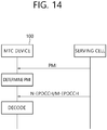
- FIG. 14 is a view illustrating an example in which a BS configures a precoding matrix used for transmission of N-EPDCCH (or M-EPDCCH), to an MTC device.
- N-EPDCCH or M-EPDCCH
- the MTC device may receive configured information regarding an index of precoding matrix (PMI) used for transmission of the N-EPDCCH (or M-EPDCCH) from a BS.
- PMI precoding matrix
- a configuration may be received from the BS through an RRC signal (or a DCI).
- the MTC device may determine a PMI applied to the N-EPDCCH (or M-EPDCCH) on the basis of the information.
- the MTC device receives a configured index of one precoding matrix from the BS and the corresponding precoding matrix is used for transmission of the N-EPDCCH (or M-EPDCCH).
- the configured precoding matrix is applied in the same manner to every PRB region in which the N-EPDCCH (or M-EPDCCH) is transmitted and a subframe region.
- the precoding matrix used for transmission of the N-EPDCCH may be varied in every PRB or bundle of PRBs.
- the BS may configure the precoding matrix used for transmission of the N-EPDCCH (or M-EPDCCH) in each PRB (or PRB bundle) to the MTC device. For example, in a case where a size of a PRB bundle to which the same precoding matrix is applied is 2 and a size of a PRB in which the N-EPDCCH (or M-EPDCCH) is transmitted is 6, the MTC device may receive three precoding matrices used for a total of three PRB bundles from the BS.
- the following methods may be considered in order to allow the MTC device to know a precoding matrix used for transmission of the N-EPDCCH (or M-EPDCCH).
- a precoding matrix used for transmission of a DMRS associated with the N-EPDCCH (or M-EPDCCH) may also be determined in the following manner.
- the following contents may also be applied in the same manner to transmission of a CRS-based N-EPDCCH (or M-EPDCCH).
- the MTC device may know a precoding matrix used for transmission of the N-EPDCCH (or M-EPDCCH) by a portion or the entirety of the following parameters.
- a precoding matrix used for the N-EPDCCH may be varied according to a current antenna port, a PRB position, and every subframe position. That is, it may be assumed that a precoding matrix used in the N-EPDCCH (or M-EPDCCH) is the same only in the same antenna port, PRB position, and subframe position in the MTC device.
- the precoding matrix used for transmission of the N-EPDCCH may be determined by an antenna port index, a PRB index, and a subframe index, for example.
- the MTC device when the MTC device knows the antenna port index, the PRB index, and the subframe index in which the N-EPDCCH (or M-EPDCCH) is transmitted, it may infer/determine a precoding matrix used for transmission of the N-EPDCCH (or M-EPDCCH) from the corresponding antenna port index, PRB index, and subframe index.
- the MTC device may receive a configured precoding matrix used for transmission of the N-EPDCCH (or M-EPDCCH) from the BS.
- the MTC device may explicitly receive a configured index of a precoding index according to an antenna port, a PRB position, and/or subframe position in which the N-EPDCCH (or M-EPDCCH) is transmitted, from the BS.
- the BS may explicitly configure only a precoding matrix according to an antenna port to the MTC device.
- a precoding matrix for the MTC device is varied only according to the antenna port and is the same, without being varied according to a PRB position and a subframe position.
- a plurality of precoding matrix patterns changing according to an antenna port, a PRB position, and/or a subframe position are present, and the BS may configure an index of a precoding matrix pattern to the MTC device.
- the index of the pattern may be transmitted through RRC signaling (or DCI).
- the precoding matrix used for transmission of the N-EPDCCH may be determined by the same parameters as those of the first method described above and the precoding matrix may be varied by explicit signaling additionally received from the BS. That is, a precoding matrix used for the N-EPDCCH (or M-EPDCCH) may be determined by the parameters of the first method described above and the precoding matrix index configured through an RRC signal (or DCI) received from the BS.
- the MTC device may infer/determine the precoding matrix used for transmission of the N-EPDCCH (or M-EPDCCH) from the corresponding antenna port index, PRB index, and subframe index.
- the precoding matrix used for transmission of the N-EPDCCH may be varied in the corresponding antenna port index, PRB index, and subframe index according to the precoding matrix index configured by the BS.
- the MTC device In a case where the N-EPDCCH (or M-EPDCCH) is channel-estimated/demodulated using a CRS and/or DMRS, the MTC device should be able always to expect the CRS and/or DMRS in the subframe in which the N-EPDCCH (or M-EPDCCH) is transmitted. Meanwhile, in the non-PDCCH transmission region of the current MBSFN subframe, the DMRS may be transmitted but the CRS may not be transmitted.
- the MTC device In a case where the MTC device always performs channel estimation/demodulation using the CRS and/or DMRS, the MTC device should be able to expect reception of the CRS and/or DMRS in the subframe in which the N-EPDCCH (or M-EPDCCH) is received. Thus, in a case where the N-EPDCCH (or M-EPDCCH) is transmitted in an MBSFN subframe, the BS should transmit the CRS and/or the DMRS in the MBSFN subframe. Transmission of the DMRS in the MBSFN subframe is not problematic but a general CRS cannot be transmitted in the MBSFN subframe. Thus, the MTC device may assume that the aforementioned narrow-CRS is received in order to receive the N-EPDCCH (or M-EPDCCH) in the MBSFN subframe.
- the MTC device may use the CRS and/or DMRS in channel estimation/demodulation for receiving the N-EPDCCH (or M-EPDCCH) in a non-MBSFN subframe (in a subframe in which the CRS is transmitted). However, since the CRS is not received in the MBSFN subframe, the MTC device may perform channel estimation/demodulation for receiving the N-EPDCCH (or M-EPDCCH) only using the DMRS.
- both the CRS and the DMRS may be transmitted in a non-PDCCH transmission region in a general subframe (i.e., non-MBSFN subframe), but only the DMRS may be transmitted in a non-PDCCH transmission region in an MBSFN subframe.
- the N-EPDCCH (or M-EPDCCH) is received on the basis of the CRS (i.e., the CRS is used for channel estimation/demodulation for receiving the N-EPDCCH (or M-EPDCCH)), and in a subframe (e.g., an MBSFN subframe) in which the CRS cannot be received and only the DMRS is received, the N-EPDCCH (or M-EPDCCH) may be received on the basis of the DMRS (i.e., the DMRS is used for channel estimation/demodulation for receiving the N-EPDCCH (or M-EPDCCH)).
- ECCEs available for transmission of an EPDCCH within an EPDCCH set Sm are numbered from 0 to N ECCE,m,i -1.
- the ECCE numbers are as follows.
- N EREG ECCE is the number of EREGs per ECCE.
- N ECCE RB 16/N EREG ECCE is the number of ECCEs per pair of resource blocks.
- the pair of resource blocks forming the EPDCCH set S m is numbered from 0 to N RB S m ⁇ 1 in an ascending order.
- ECCE to EREG mapping relation of two methods may be considered.
- mapping method for localized transmission as described above and the other is a mapping method for distributed transmission as described above.
- both mapping of localized transmission and mapping of distributed transmission should be used for ECCE to EREG mapping, regardless of transmission type (e.g., localized transmission or distributed transmission).
- the BS may configure which of mapping of localized transmission and mapping of distributed transmission is to be used to transmit the N-EPDCCH (or M-EPDCCH) through higher layer signalling or SIB to the MTC device.
- the MTC device may attempt to receive the N-EPDCCH (or M-EPDCCH) through blind decoding on the assumption that the N-EPDCCH (or M-EPDCCH) can be transmitted in both of the two methods.
- both mapping of localized transmission and mapping of distributed transmission may be used in the mapping relation of the EREGs forming the ECCE of the N-EPDCCH (or M-EPDCCH).
- the MTC device cannot use a region of OFDM symbols transmitted for the legacy PDCCH.
- the MTC device may operate on the assumption that a relatively small number of OFDM symbols (e.g., 12 OFDM symbols per subframe), compared with the legacy MTC device, is present. Also, in the case of considering a CRS-based N-EPDCCH (or M-EPDCCH), since a DMRS is not transmitted in the PRB region in which the N-EPDCCH (or M-EPDCCH) is transmitted, an RE resource region in which the DMRS is transmitted may not be considered when the N-EPDCCH (or M-EPDCCH) is transmitted.
- a CRS-based N-EPDCCH or M-EPDCCH
- the present disclosure newly proposes RE mapping of EREG within an RB for N-EPDCCH (or M-EPDCCH).
- RE mapping of an EREG may be performed in consideration of an OFDM symbol region in which a legacy PDCCH is transmitted.
- RE mapping of an EREG of N-EPDCCH may be performed in consideration of the fact that three OFDM symbols are used for the legacy PDCCH.
- RE resource positioned in the OFDM symbols #0, #1, and #2 in which the legacy PDCCH is transmitted and RE resource in which the DMRS (DMRS for antenna ports 107, 108, 109, and 110) is transmitted may be excluded from the RE mapping of the EREG of the N-EPDCCH (or M-EPDCCH).
- RE resource positioned in the OFDM symbols #0, #1, and #2 in which the legacy PDCCH is transmitted and RE resource in which the DMRS (DMRS for antenna ports 107, 108, 109, and 110) is transmitted may be excluded from the EREG.
- a total of 108 REs per RB may be used for RE mapping of the EREG, and a total of 12 EREGs, each including 9 REs, per RB may be present.
- RE mapping of the EREG may be performed in consideration of an OFDM symbol region in which the legacy PDCCH is transmitted and/or an RE resource region in which the CRS is transmitted.
- RE mapping of the EREG of the N-EPDCCH may be performed in consideration of that two OFDM symbols will be used for the legacy PDCCH.
- RE resource positioned in the OFDM symbols #0 and #1 in which the legacy PDCCH is transmitted may be excluded from the RE mapping of the EREG of the N-EPDCCH (or M-EPDCCH). That is, the RE resource positioned in the OFDM symbols #0 and #1 in which the legacy PDCCH is transmitted may be excluded from the EREG.
- a total of 144 REs per RB may be used for RE mapping of the EREG, and a total 16 EREGs, each including 9 REs, per RB may be present.
- FIG. 15A illustrates a first example regarding RE mapping of an EREG in a CRS-based N-EPDCCH (or M-EPDCCH).
- FIG. 15A it is assumed that two OFDM symbols are present for a PDCCH.
- REs of an EREG may be included in an RB.
- REs forming a single EREG are indicated by the same numbers.
- RE mapping of an EREG of an N-EPDCCH may be performed in consideration of the use of one OFDM symbol for the legacy PDCCH and in consideration of RE positions of a CRS port 0 and a CRS port 1.
- RE resource positioned in the OFDM symbol #0 in which the legacy PDCCH is transmitted and RE resource in which the CRS port 0 and the CRS port 1 are transmitted may be excluded from the RE mapping of an EREG of an N-EPDCCH (or M-EPDCCH). That is, RE resource positioned in the OFDM symbol #0 in which the legacy PDCCH is transmitted and RE resource in which the CRS port 0 and the CRS port 1 are transmitted may be excluded from the EREG.
- the N-EPDCCH (or M-EPDCCH) may be rate-matched and transmitted in the RE resource in which the CRS ports 2 and 3 are transmitted.
- a total of 144 REs per RB may be used for RE mapping of the EREG, and a total of 16 EREGs, each including 9 REs, per RB may be present.
- FIG. 15B illustrates a second example regarding RE mapping of an EREG of a CRS-based N-EPDCCH (or M-EPDCCH).
- FIG. 15B it is assumed that one OFDM symbol for a PDCCH is provided and a CRS is transmitted through one antenna port.
- REs of an EREG may be configured within an RB as illustrated in FIG. 15B .
- REs forming one EREG are indicated by the same number.
- the EREG RE mapping technique when used, since the number of EREGs present within an RB and the number of REs forming the EREGs are the same as those of the legacy EPDCCH, complexity of implementation is reduced. However, since a transmission RE position of the CRS is varied according to a physical cell ID/v-shift value, an RE position forming one EREG is varied according to a position of the CRS.
- the EREG-to-RE mapping according to a position of the CRS may be newly mapped according to a rule such as "increasing order of first the subcarrier index and then the OFDM symbol index starting with the first slot and ending with the second slot" within a PRB in consideration of the changed CRS position.
- v-shift may be performed together with the EREG-to-REG mapping within the PRB by the v-shifted position of the CRS.
- the MTC device may be assumed as follows.
- the MTC device may assume that the CRS is transmitted through the antenna port 0 also in the RE region in which the CRS is transmitted through the antenna port 1.
- the above assumption may be made only in the OFDM symbol region in which the legacy PDCCH is not transmitted. Or, characteristically, the above assumption may be made only in an OFDM symbol region after an "OFDM symbol position in which transmission of the N-EPDCCH (or M-EPDCCH) configured for the MTC device through RRC signalling" starts.
- RE mapping of the EREG of the N-EPDCCH may be performed in consideration of the use of three OFDM symbols for the legacy PDCCH and in consideration of an RE position of the CRS port 0.
- RE resource positioned in the OFDM symbols #0, #1, and #2 in which the legacy PDCCH is transmitted and RE resource in which the CRS port 0 is transmitted may be excluded from the RE mapping of the EREG of the N-EPDCCH (or M-EPDCCH). That is, RE resource positioned in the OFDM symbols #0, #1, and #2 in which the legacy PDCCH is transmitted and RE resource in which the CRS port 0 is transmitted may be excluded from the EREG.
- the N-EPDCCH (or M-EPDCCH) may be rate-matched and transmitted in the RE resource in which the CRS ports 1, 2, and 3 are transmitted.
- a total of 108 REs per RB may be used for RE mapping of the EREG, and a total of 12 EREGs, each including 9 REs, per RB may be present.
- FIG. 15C illustrates a third example regarding RE mapping of the EREG of the CRS-based N-EPDCCH (or M-EPDCCH)
- FIG. 15C it is assumed that three OFDM symbols for a PDCCH are provided and one CRS is transmitted through one antenna port.
- REs of an EREG may be configured within an RB.
- REs forming one EREG are indicated by the same number.
- a transmission RE position of the CRS is varied according to a physical cell ID/v-shift value
- an RE position forming one EREG is varied according to a position of the CRS.
- the EREG-to-RE mapping according to a position of the CRS may be newly mapped according to a rule such as "increasing order of first the subcarrier index and then the OFDM symbol index starting with the first slot and ending with the second slot" within a PRB in consideration of the changed CRS position.
- v-shift may be performed together with the EREG-to-REG mapping within the PRB by the v-shifted position of the CRS.
- RE mapping of an EREG of an N-EPDCCH may be performed in consideration of the use of zero (0) OFDM symbol for the legacy PDCCH and in consideration of RE positions of CRS ports 0, 1, 2, and 3.
- RE resource in which the CRS ports 0, 1, 2, and 3 are transmitted may be excluded from the RE mapping of an EREG of an N-EPDCCH (or M-EPDCCH). That is, the RE resource in which the CRS ports 0, 1, 2, and 3 are transmitted may be excluded from the EREG.
- a total of 144 REs per RB may be used for RE mapping of the EREG, and a total of 16 EREGs, each including 9 REs, per RB may be present.
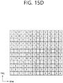
- FIG. 15D illustrates a fourth example regarding RE mapping of an EREG of a CRS-based N-EPDCCH (or M-EPDCCH).
- FIG. 15B it is assumed that zero (0) OFDM symbol for a PDCCH is provided and a CRS is transmitted through four antenna ports.
- REs of an EREG may be configured within an RB as illustrated in FIG. 15D .
- REs forming one EREG are indicated by the same number.
- the EREG-to-RE mapping according to a position of the CRS may be newly mapped according to a rule such as "increasing order of first the subcarrier index and then the OFDM symbol index starting with the first slot and ending with the second slot" within a PRB in consideration of the changed CRS position.
- v-shift may be performed together with the EREG-to-REG mapping within the PRB by the v-shifted position of the CRS.
- the MTC device may be assumed as follows.
- the MTC device may assume that the CRS is transmitted through the antenna port 0 also in the RE region in which the CRS is transmitted through the antenna ports 1, 2, and 3.
- the MTC device may assume that the CRS is transmitted through the antenna ports 0 and 1 also in the RE region in which the CRS is transmitted through the antenna ports 2 and 3. For example, it may be assumed that the CRS is transmitted through the antenna port 0 in the RE region in which the CRS is transmitted through the antenna port 2 and the CRS is transmitted through the antenna port 1 in the RE region in which the CRS is transmitted is transmitted through the antenna port 3.
- the corresponding RE position is not empted but may be used for additionally transmitting the CRS through the antenna port in which the CRS is transmitted.
- the above assumption may be made only in the OFDM symbol region in which the legacy PDCCH is not transmitted. Or, characteristically, the above assumption may be made only in an OFDM symbol region after an "OFDM symbol position in which transmission of the N-EPDCCH (or M-EPDCCH) configured for the MTC device through RRC signalling" starts.
- an MTC device with low complexity is generally expected not to have high performance, and an MTC device requiring coverage enhancement is expected to operate in a low SINR region.
- it may be meaningless to transmit the CRS through four antenna ports to the MTC device and perform data transmission.
- the antenna ports 2 and 3 since density of reference signals (RSs) is low, compared with the antenna ports 0, 1, channel estimation performance may not be good.
- RSs reference signals
- the BS may use only two antenna ports for an MTC device requiring coverage enhancement (and/or an MTC device with low complexity). That is, when the number of CRS ports determined by the MTC device through blind decoding of a PBCH is greater than 2, the MTC device requiring coverage enhancement (and/or an MTC device with low complexity) may perform reception on the assumption that an N-PDCCH and a PDSCH are transmitted through the CRS of two ports.
- the MTC device may use only the EREG to RE mapping such as that of FIG. 15D .
- CRS transmission in the PRB region in which the N-EPDCCH (or M-EPDCCH) is transmitted may be as follows.
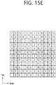
- the MTC device may use EREG to RE mapping such as that of FIG. 15E .
- FIG. 15E illustrates a fifth example regarding RE mapping of an EREG of a CRS-based N-EPDCCH (or M-EPDCCH).
- the RE mapping of an EREG illustrated in FIG. 15E excludes RE resource used by the CRS antenna ports 0 and 1 in an extended CP environment. In this case, a total of 16 RE resources per RB are excluded from EREG-to-RE mapping in the same as that of EREG-to-RE mapping.
- CRS transmission may be as follows.
- the MTC device may assume that CRS is transmitted on the assumption of two ports (antenna ports 0 and 1) in both non-MBSFN subframe and MBSFN subframe.
- RE mapping of an EREG may be performed in consideration of an OFDM symbol region in which a legacy PDCCH is transmitted, an RE resource region in which a DMRS is transmitted, and/or an RE resource region in which a CRS is transmitted.
- EREG-to-RE mapping of the N-EPDCCH may be configured in consideration of only i) the DMRS, ii) only the CRS, or iii) both DMRS and CRS, among the CMRS and the CRS.
- the EREG-to-RE mapping as in the legacy EPDCCH may be used as is.
- EREG-to-RE mapping considers only the CRS among the DMRS and the CRS
- EREG-to-RE mapping of the specified CRS-based N-EPDCCH (or M-EPDCCH) may be applied.
- EREG-to-RE mapping may be performed in consideration of a transmission RE position of the entire or partial ports of the DMRS or a transmission RE position of the entire or partial ports of the CRS.
- EREG-to-RE mapping may be performed using only an RE position excluding an RE position of the DMRS which can be transmitted through every antenna port and an RE position of the CRS which can be transmitted through the antenna ports 0 and 1.
- EREG-to-RE mapping may be performed using only an RE position excluding an RE position of the DMRS which can be transmitted through every antenna port and an RE position of the CRS which can be transmitted through the antenna ports 0, 1, 2 and 3.
- Mapping regarding resource elements (k, 1) of an antenna port P may be performed in order of an index k and an index 1 which start from a first slot of a subframe and end in a second slot of the subframe.
- an antenna port used for transmission of a DMRS and/or N-EPDCCH (or M-EPDCCH) regarding a DMRS-based N-EPDCCH (or M-EPDCCH) or CRS and/or DMRS-based N-EPDCCH (or M-EPDCCH) may be the same as an antenna port used for transmission of a legacy distributed EPDCCH.
- an antenna port used for transmission of a DMRS and/or N-EPDCCH (or M-EPDCCH) regarding a DMRS-based N-EPDCCH (or M-EPDCCH) or CRS and/or DMRS-based N-EPDCCH (or M-EPDCCH) may be different from an antenna port used for transmission of a legacy distributed EPDCCH as follows.
- an antenna port used for transmission of a CRS and/or N-EPDCCH (or M-EPDCCH) regarding the CRS-based N-EPDCCH (or M-EPDCCH) may be as follows.
- an antenna port used for transmission of a CRS and/or N-EPDCCH (or M-EPDCCH) regarding a DMRS-based N-EPDCCH (or M-EPDCCH) or CRS and/or DMRS-based N-EPDCCH (or M-EPDCCH) may be as follows.
- an antenna port used for transmission of a DMRS and/or N-EPDCCH (or M-EPDCCH) regarding a DMRS-based N-EPDCCH (or M-EPDCCH) or CRS and/or DMRS-based N-EPDCCH (or M-EPDCCH) may be different from an antenna port used for transmission of a legacy distributed EPDCCH as follows.
- an antenna port used for transmission of a CRS and/or N-EPDCCH (or M-EPDCCH) regarding the CRS-based N-EPDCCH (or M-EPDCCH) may be as follows.
- a CSI-RS (e.g., ZP CSI-RS, NZP CSI-RS) may be transmitted through a transmission resource region of the N-EPDCCH (or M-EPDCCH), unlike the case in which the SFBC is applied to the legacy PDCCH.
- FIGS. 16A and 16B illustrate an example of an SFBC using two antennas.
- symbols S(i) and S(i+1) may be transmitted in the same OFDM symbol, S(i) may be transmitted through an antenna port y and an antenna port y+b in a subcarrier x and a subcarrier x+a, and S(i+1) may be transmitted through an antenna port y+b and an antenna port y in the subcarrier x and the subcarrier x+a.
- S(i) S(i+1) may be called an SFBC pair.
- N-EPDCCH (or M-EPDCCH) is rate-matched and transmitted in the RE position in which a CSI-RS is transmitted so a value of a as an interval between the subcarriers (subcarrier x and subcarrier x+a) in which one SFBC pair is transmitted is greater than 2, a change in channels between the subcarrier x and the subcarrier x+a is increased to reduce performance of the SFBC.
- transmission of the N-EPDCCH is rate-matched in the subcarrier x.
- the N-EPDCCH (or M-EPDCCH) is not transmitted in the rate-matched RE position.
- the corresponding SFBC pair may start to be transmitted in a first subcarrier among the subcarrier x+a or subcarriers in which the N-EPDCCH (or M-EPDCCH) is transmissible after the subcarrier x+a.
- transmission of the N-EPDCCH is rate-matched in both the subcarriers x and x+a.
- the N-EPDCCH (or M-EPDCCH) is not transmitted in the RE position in which the N-EPDCCH (or M-EPDCCH) was rate-matched.
- the corresponding SFBC may start to transmit the N-EPDCCH (or M-EPDCCH) through the subcarrier x+a+1 or a first subcarrier among transmittable subcarriers after the subcarrier x+a+1.
- the N-EPDCCH (or M-EPDCCH) is transmitted in the subcarrier x and transmission of the corresponding SFBC pair is dropped in a subcarrier x+a.
- transmission of a next SFBC pair may start in the subcarrier x+a.
- the number of transmittable subcarriers of the N-EPDCCH (or M-EPDCCH) within an OFDM symbol is an odd number, and thus, one SFBC pair may not be fully transmitted within the same OFDM symbol.
- the number of subcarriers (Res) within the OFDM symbol may be insufficient, causing a case in which the one SFBC pair cannot be fully transmitted within the same OFDM symbol.
- transmission of the N-EPDCCH is rate-matched in the subcarrier x.
- the corresponding SFBC pair may be transmitted through the next OFDM symbol.
- the N-EPDCCH (or M-EPDCCH) is transmitted in the subcarrier x and transmission of the remaining of the SFBC pair is dropped.
- transmission of the next SFBC pair may start in a next OFDM symbol.
- transmission of the N-EPDCCH is rate-matched in the entire corresponding OFDM symbol.
- an RE position in which one SFBC pair is transmitted is positioned to be as close as possible.
- EREG forming one ECCE are formed not to have a continuous index, RE positions of the EREGs forming the ECCE do not have continuously subcarrier positions but have distributed subcarrier positions.
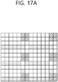
- FIGS. 17A and 17B illustrate an example of an SFBC.
- an aggregation level (AL) is 1 in mapping of localized transmission
- a subcarrier position of REs forming one EPDDCH candidate are not continuously positioned as illustrated in FIG. 17A .
- the AL is 2 or greater
- at least two REs are positioned in continuous subcarriers as illustrated in FIG. 17B .
- the AL may be limited to be 4 or greater.
- EREGs forming one ECCE in order to continuously position positions of subcarriers of REs forming one EPDCCH candidate, when the N-EPDCCH (or M-EPDCCH) is applied to the SFBC, it is proposed for EREGs forming one ECCE to have continuous indices. That is, for example, it is proposed to apply the following ECCE to EREG mapping.
- ECCEs available for transmission of the EPDCCH within an EPDCCH set Sm in a subframe i are numbered from 0 to N ECCE,m,i -1.
- the ECCE numbers are as follows.
- N EREG ECCE is the number of EREGs per ECCE.
- N ECCE RB 16/N EREG ECCE is the number of ECCEs per pair of resource blocks.
- the pair of resource blocks forming the EPDCCH set S m is numbered from 0 to N RB S m ⁇ 1 in an ascending order.
- transmission of a DMRS transmitted through a partial frequency region for demodulation of the N-EPDCCH may be as follows.
- the DMRS will be described as an example, but the following contents may also be applied to an RS transmitted through a partial frequency region for demodulation of the N-EPDCCH (or M-EPDCCH) like the narrow-CRS transmitted in the MBSFN subframe.
- the DMRS may be transmitted through the PRB region in which the N-EPDCCH (or M-EPDCCH) is actually transmitted to the MTC device.
- the N-EPDCCH or M-EPDCCH
- a position of the PRB region in which the DMRS is transmitted is also changed together.
- cross-subframe channel estimation as a technique for increasing channel estimation performance in an environment with less mobility of the MTC device cannot be performed.
- the N-EPDCCH (or M-EPDCCH) should be transmitted at the same aggregation level during the repetition
- ii) the N-EPDCCH (or M-EPDCCH) should be transmitted through the same N-EPDCCH (or M-EPDCCH) candidates during the repetition
- iii) the ECCE indices forming one N-EPDCCH (or M-EPDCCH) candidate should be maintained during the repetition or should be maintained during a predetermined time interval.
- the DMRS may be transmitted through a reduced band region (e.g., six PRB regions) in which the low-cost MTC device operates. That is, for the MTC device, it may be assumed that the DMRS is transmitted through the entire regions of six PRBs which can be received by the MTC device. In this case, since the amount of resource of the DMRS transmitted within one subframe is increased, compared with the first method, channel estimation performance in the subframe may be enhanced and cross-subframe channel estimation may also be performed. In particular, the DMRS may be transmitted only when the EPDCCH is actually transmitted to the MTC device.
- a reduced band region e.g., six PRB regions
- the DMRS may be transmitted through the entire PRB regions forming an N-EPDCCH (or M-EPDCCH)-PRB-set.
- N-EPDCCH or M-EPDCCH
- the DMRS may be transmitted through the four PRBs.
- the DMRS may be transmitted only in a case where the EPDCCH is transmitted is actually transmitted to the MTC device.
- the actual EPDCCH is transmitted only in one PRB region, since the DMRS is transmitted through a larger PRE region, channel estimation performance within a subframe may be enhanced and cross-subframe channel estimation may also be performed.
- cell-common channels e.g., PSS/SSS, PBCH, etc.
- data e.g., SIB
- the MTC device-specific channels may be transmitted through six PRB regions different for each MTC device but cell-common channels (e.g., PSS/SSS, PBCH, etc.) or data (e.g., SIB) may be transmitted through six central PRB regions of the system bandwidth of the cell. That is, a resource region in which the MTC device performs CSS monitoring should be transmitted through the cell-common sub-band resource region (e.g., the six central PRBs of the system bandwidth of the cell).
- a cell-common PDSCH such as an SIB may also be scheduled through the EPDCCH.
- the MTC device cannot obtain a configuration associated with transmission of the EPDCCH before reading an SIB at an initial connection stage regarding the cell.
- the MTC device should know information related to CSS on the EPDCCH without receiving higher layer signalling.
- the MTC device may attempt at CSS monitoring through six central PRB resources of the system bandwidth of the cell.
- a subframe resource for the MTC device to monitor a CSS of the EPDCCH may be defined in advance. It may be defined in the form of a subframe period, duration, and offset, for example.
- the MTC device may assume that transmission of the EPDCCH starts from the OFDM symbol #M.
- the MTC device may monitor only one EPDCCH-PRB-set for CSS monitoring.
- a PRB position of the corresponding EPDCCH-PRB-set may be defined in advance.
- the PRB position may be defined in advance by a specific 1 RB (e.g., PRB #0) within resource of 6 PRBs received by the MTC device.
- An EPDCCH transmission type within the EPDCCH-PRB-set for CSS monitoring may be defined in advance.
- the MTC device may assume that the EPDCCH for CSS monitoring is always transmitted in the form of distributed transmission.
- a scrambling sequence initialization parameter (i.e., n ID , i EPDCCH ) for transmission of the EPDCCH and a DMRS associated with the EPDCCH may be fixed to a specific value.
- a value of the scrambling sequence initialization parameter may be the same as a physical cell ID of a cell.
- a CSS region of the EPDCCH may not be a cell-common sub-band resource region (e.g., six central PRBs), but an EPDCCH CSS region may be present in each of a plurality of sub-band regions as illustrated in FIG. 13B .
- the EPDCCH e.g., EPDCCH scrambled with SI-RNTI, R-RNTI, and/or P-RNTI
- the MTC device may monitor the EPDCCH CSS in the sub-band region in which the MTC device operates, rather than switching a frequency (sub-band) from the sub-band region in which the MTC device operates to the cell-common sub-band region.
- the EPDCCH or the modified EPDCCH rather than a PDCCH
- the MTC device operating in a partial band (e.g., six PRBs), rather than in the entire system band of the cell, receives the EPDCCH in the six central PRB regions
- a resource region for transmitting the EPDCCH is very limited due to a legacy PBCH and a legacy PSS/SSS in the subframe #0.
- the DMRS is not transmitted in the six central PRB regions due to resource collision with the PSS/SSS.
- the current EPDCCH may not be normally transmitted in the six central PRB regions of the subframe #0.
- a resource region for transmitting the EPDCCH is limited due to the legacy PSS/SSS, and the DMRS is not transmitted in the six central PRB regions due to resource collision with the PSS/SSS.
- the current EPDCCH may not be normally transmitted in the six central PRB regions of the subframe #5.
- the EPDCCH may be transmitted in the six central PRB regions of the subframes #0 (and #5).
- FIG. 18 illustrates an example in which a DCI, which is to be transmitted in the subframes #0 (and #5), in a preceding subframe.
- the downlink grant scheduling a PDSCH transmitted in a subframe #1 may be transmitted through a subframe #9 (#-1) (subframe #4), a preceding subframe, rather than being transmitted through the original subframe #0 (subframe #5) as illustrated in FIG. 18 .
- information regarding whether the corresponding downlink grant is for scheduling a PDSCH transmitted through which subframe may be indicated through a specific field, e.g., a DAI field, within the downlink grant.
- the downlink grant scheduling a PDSCH transmitted in a subframe #0 may be transmitted through a subframe #9 (#-1) (subframe #4), a preceding subframe, rather than being transmitted through the original subframe #0 (subframe #5).
- information regarding whether the corresponding downlink grant is for scheduling a PDSCH transmitted through which subframe may be indicated through a specific field, e.g., a downlink assignment index (DAI) field, within the downlink grant.
- DAI downlink assignment index
- an uplink grant scheduling a PUSCH transmitted in a subframe #4 may be transmitted through a subframe #9 (#-1) (subframe #4), a preceding subframe, rather than being transmitted through the original subframe #0 (subframe #5).
- information regarding whether the corresponding downlink grant is for scheduling a PUSCH transmitted through which subframe may be indicated through a specific field, e.g., a DAI field, within the uplink grant.
- an EPDCCH may be repeatedly transmitted in multiple subframes to extend coverage.
- the MTC device may assume that the EPDCCH transmission is not performed in the corresponding subframe and exclude the corresponding subframe from a bundle of subframes in which the EPDCCH is repeatedly transmitted.
- the contents described above may also be applied to transmission of other channels (e.g., a PBCH or a PDSCH), as well as to transmission of the N-EPDCCH.
- other channels e.g., a PBCH or a PDSCH
- FIG. 19 is a block diagram illustrating the wireless communication system in which one embodiment of the present invention is implemented.
- a BS 200 includes a processor 201, a memory 202 and an RF (radio frequency) unit 203.
- the memory 202 is connected to the processor 201, and stores various information for driving the processor 201.
- the RF unit 203 is connected to the processor 201, and transmits and/or receives radio signals.
- the processor 201 implements proposed functions, processes and/or methods. In the afore-mentioned embodiment, the operation of the BS 200 can be implemented by the processor 201.
- An MTC 100 includes a processor 101, a memory 102 and an RF unit 103.
- the memory 102 is connected to the processor 101, and stores various information for driving the processor 101.
- the RF unit 103 is connected to the processor 101, and transmits and/or receives radio signals.
- the processor 101 implements proposed functions, processes and/or methods.
- the processor may include Application-Specific Integrated Circuits (ASICs), other chipsets, logic circuits, and/or data processors.
- the memory may include Read-Only Memory (ROM), Random Access Memory (RAM), flash memory, memory cards, storage media and/or other storage devices.
- the RF unit may include a baseband circuit for processing a radio signal.
- the above-described scheme may be implemented using a module (process or function) which performs the above function.
- the module may be stored in the memory and executed by the processor.
- the memory may be disposed to the processor internally or externally and connected to the processor using a variety of well-known means.
Applications Claiming Priority (7)
| Application Number | Priority Date | Filing Date | Title |
|---|---|---|---|
| US201462054404P | 2014-09-24 | 2014-09-24 | |
| US201462073036P | 2014-10-31 | 2014-10-31 | |
| US201462090888P | 2014-12-12 | 2014-12-12 | |
| US201462096546P | 2014-12-24 | 2014-12-24 | |
| US201562108546P | 2015-01-28 | 2015-01-28 | |
| US201562135678P | 2015-03-19 | 2015-03-19 | |
| PCT/KR2015/010079 WO2016048055A1 (fr) | 2014-09-24 | 2015-09-24 | Procédé et dispositif mtc permettant de recevoir un canal de commande de liaison descendante |
Publications (3)
| Publication Number | Publication Date |
|---|---|
| EP3200412A1 true EP3200412A1 (fr) | 2017-08-02 |
| EP3200412A4 EP3200412A4 (fr) | 2018-06-20 |
| EP3200412B1 EP3200412B1 (fr) | 2020-11-04 |
Family
ID=55581483
Family Applications (1)
| Application Number | Title | Priority Date | Filing Date |
|---|---|---|---|
| EP15844009.9A Active EP3200412B1 (fr) | 2014-09-24 | 2015-09-24 | Procédé et dispositif sans fil permettant de recevoir un canal de commande de liaison descendante |
Country Status (6)
| Country | Link |
|---|---|
| US (1) | US10455565B2 (fr) |
| EP (1) | EP3200412B1 (fr) |
| JP (1) | JP6426280B2 (fr) |
| KR (1) | KR20170063513A (fr) |
| CN (1) | CN107078875B (fr) |
| WO (1) | WO2016048055A1 (fr) |
Cited By (2)
| Publication number | Priority date | Publication date | Assignee | Title |
|---|---|---|---|---|
| US10856161B2 (en) | 2016-12-05 | 2020-12-01 | Telefonaktiebolaget Lm Ericsson (Publ) | Controlling lean carrier operation with configurable control channel monitoring |
| US11190319B2 (en) | 2016-12-05 | 2021-11-30 | Telefonaktiebolaget Lm Ericsson (Publ) | Controlling cell-specific reference signal (CRS) bandwidth on a lean carrier based on another reference signal bandwidth |
Families Citing this family (20)
| Publication number | Priority date | Publication date | Assignee | Title |
|---|---|---|---|---|
| WO2011043497A1 (fr) * | 2009-10-06 | 2011-04-14 | Pantech Co., Ltd. | Précodage et informations de canal de retour dans un système de communication sans fil |
| WO2016133363A1 (fr) * | 2015-02-17 | 2016-08-25 | 엘지전자 주식회사 | Procédé de communication stbc mimo en liaison montante dans un système de communication sans fil et appareil associé |
| US10652768B2 (en) * | 2015-04-20 | 2020-05-12 | Qualcomm Incorporated | Control channel based broadcast messaging |
| US10530432B2 (en) * | 2015-05-25 | 2020-01-07 | Sony Corporation | Wireless communication device, terminal device, and method |
| US11109372B2 (en) * | 2016-01-11 | 2021-08-31 | Qualcomm Incorporated | Narrow-band physical control channel design |
| US10681633B2 (en) * | 2016-04-05 | 2020-06-09 | Qualcomm Incorporated | Configurable subframe structures in wireless communication |
| CN107370588B (zh) | 2016-05-13 | 2021-04-20 | 华为技术有限公司 | 参考信号的发送方法及设备 |
| CN107453794B (zh) * | 2016-05-31 | 2020-12-08 | 中兴通讯股份有限公司 | 信息反馈方法、装置及系统 |
| US10574425B2 (en) | 2016-06-28 | 2020-02-25 | Lg Electronics Inc. | Method for receiving downlink signal and user equipment, and method for transmitting downlink signal and base station |
| CN108135030B (zh) * | 2016-09-30 | 2020-10-23 | 华为技术有限公司 | 传输物理控制信道的指示方法及其装置 |
| CN107889245B (zh) * | 2016-09-30 | 2023-11-14 | 华为技术有限公司 | 无线通信的方法和设备 |
| US10469159B2 (en) | 2017-02-14 | 2019-11-05 | Qualcomm Incorporated | Narrowband time-division duplex frame structure for narrowband communications |
| US10420102B2 (en) | 2017-02-15 | 2019-09-17 | Qualcomm Incorporated | Narrowband time-division duplex frame structure for narrowband communications |
| JP6857538B2 (ja) * | 2017-04-14 | 2021-04-14 | 株式会社Nttドコモ | 無線基地局 |
| WO2018209596A1 (fr) * | 2017-05-17 | 2018-11-22 | Qualcomm Incorporated | Configuration de csi-rs pour réajustement de bande partielle |
| WO2019095188A1 (fr) | 2017-11-16 | 2019-05-23 | Qualcomm Incorporated | Techniques et appareils de gestion de porteuses |
| DE102018205351A1 (de) * | 2018-04-10 | 2019-10-10 | Volkswagen Aktiengesellschaft | Verfahren und Vorrichtung zur Anpassung mindestens eines Parameters eines Kommunikationssystems |
| US11799691B2 (en) | 2018-08-09 | 2023-10-24 | Lg Electronics Inc. | Method for estimating channel by terminal in wireless communication system, and device therefor |
| CN112514301B (zh) * | 2018-08-10 | 2023-12-01 | 英特尔公司 | 与机器类型通信系统相关联的装置和计算机可读存储设备 |
| CN110536270B (zh) * | 2018-09-28 | 2023-09-01 | 中兴通讯股份有限公司 | 数据发送、接收方法、装置、终端、基站及存储介质 |
Family Cites Families (16)
| Publication number | Priority date | Publication date | Assignee | Title |
|---|---|---|---|---|
| US20110222629A1 (en) | 2008-11-20 | 2011-09-15 | Nokia Corporation | Pre-coding for downlink control channel |
| CN102291731A (zh) * | 2010-06-18 | 2011-12-21 | 电信科学技术研究院 | 一种应用于分层网络的测量方法及其装置 |
| EP2640152A4 (fr) * | 2010-11-08 | 2016-08-24 | Lg Electronics Inc | Procédé de connexion rrc et dispositif associé dans un système de communication sans fil |
| EP3544219A1 (fr) * | 2011-08-12 | 2019-09-25 | InterDigital Patent Holdings, Inc. | Fonctionnement de bande passante flexible dans des systèmes sans fil |
| US8842628B2 (en) * | 2011-09-12 | 2014-09-23 | Blackberry Limited | Enhanced PDCCH with transmit diversity in LTE systems |
| US9515799B2 (en) * | 2011-09-29 | 2016-12-06 | Lg Electronics Inc. | Method of transmitting control information for low-cost machine type communication, and apparatus for supporting same |
| KR20190044141A (ko) * | 2011-09-30 | 2019-04-29 | 인터디지탈 패튼 홀딩스, 인크 | 감소된 채널 대역폭을 사용하는 장치 통신 |
| US20130094457A1 (en) * | 2011-10-14 | 2013-04-18 | Electronics And Telecommunications Research Institute | Data transmission and reception method of machine type communication (mtc) device |
| CN103178942B (zh) * | 2011-12-21 | 2016-08-03 | 华为技术有限公司 | 信令传输方法、基站和用户设备 |
| JP2013183299A (ja) | 2012-03-02 | 2013-09-12 | Sharp Corp | 移動局装置、基地局装置、通信方法、集積回路および無線通信システム |
| US9338773B2 (en) * | 2012-03-26 | 2016-05-10 | Qualcomm Incorporated | Common search space for EPDCCH in LTE |
| TR201820348T4 (tr) * | 2012-05-11 | 2019-01-21 | Ericsson Telefon Ab L M | Downlink programlaması için aygıt ve usul. |
| JP6105211B2 (ja) | 2012-05-11 | 2017-03-29 | 株式会社Nttドコモ | 基地局装置、無線通信端末、無線通信システム及び無線通信方法 |
| GB2506583A (en) * | 2012-08-31 | 2014-04-09 | Sony Corp | Inserting a virtual narrowband carrier in wideband carrier of a mobile communications system |
| US10142962B2 (en) | 2012-10-05 | 2018-11-27 | Interdigital Patent Holdings, Inc. | Method and apparatus for enhancing coverage of machine type communication (MTC) devices |
| WO2014069946A1 (fr) | 2012-11-01 | 2014-05-08 | Lg Electronics Inc. | Procédé et appareil pour gérer des groupes de programmation de caractéristiques de dispositifs dans un système de communication sans fil |
-
2015
- 2015-09-24 EP EP15844009.9A patent/EP3200412B1/fr active Active
- 2015-09-24 US US15/509,162 patent/US10455565B2/en active Active
- 2015-09-24 JP JP2017516342A patent/JP6426280B2/ja active Active
- 2015-09-24 CN CN201580051802.8A patent/CN107078875B/zh active Active
- 2015-09-24 KR KR1020177003699A patent/KR20170063513A/ko not_active IP Right Cessation
- 2015-09-24 WO PCT/KR2015/010079 patent/WO2016048055A1/fr active Application Filing
Cited By (3)
| Publication number | Priority date | Publication date | Assignee | Title |
|---|---|---|---|---|
| US10856161B2 (en) | 2016-12-05 | 2020-12-01 | Telefonaktiebolaget Lm Ericsson (Publ) | Controlling lean carrier operation with configurable control channel monitoring |
| US11190319B2 (en) | 2016-12-05 | 2021-11-30 | Telefonaktiebolaget Lm Ericsson (Publ) | Controlling cell-specific reference signal (CRS) bandwidth on a lean carrier based on another reference signal bandwidth |
| EP3549294B1 (fr) * | 2016-12-05 | 2023-02-01 | Telefonaktiebolaget LM Ericsson (publ) | Commande d'opération de porteuse maigre avec surveillance configurable de canal de commande |
Also Published As
| Publication number | Publication date |
|---|---|
| EP3200412B1 (fr) | 2020-11-04 |
| KR20170063513A (ko) | 2017-06-08 |
| US10455565B2 (en) | 2019-10-22 |
| JP6426280B2 (ja) | 2018-11-28 |
| US20170273059A1 (en) | 2017-09-21 |
| JP2017536719A (ja) | 2017-12-07 |
| WO2016048055A1 (fr) | 2016-03-31 |
| CN107078875B (zh) | 2021-04-27 |
| CN107078875A (zh) | 2017-08-18 |
| EP3200412A4 (fr) | 2018-06-20 |
Similar Documents
| Publication | Publication Date | Title |
|---|---|---|
| EP3200412B1 (fr) | Procédé et dispositif sans fil permettant de recevoir un canal de commande de liaison descendante | |
| US10856321B2 (en) | Method and wireless device for receiving PDSCH | |
| US10560873B2 (en) | Reception method of MTC device | |
| US10027524B2 (en) | Method and apparatus for transmitting reference signal | |
| EP3136641B1 (fr) | Procédé et terminal pour transmettre un signal de référence de sondage dans un système de communication sans fil | |
| EP3214793B1 (fr) | Procédé de transmission de pucch par un dispositif mtc | |
| EP3073658B1 (fr) | Procédé de réception d'un groupe de pdcch, et dispositif de mtc | |
| EP3086491B1 (fr) | Procédé et terminal pour recevoir un regroupement d'epdcch | |
| US9510365B2 (en) | Signal-transceiving method, and apparatus therefor | |
| EP3016302B1 (fr) | Procédé et appareil d'acquisition d'informations de commande dans un système de communication sans fil | |
| EP2892169A2 (fr) | Procédé et dispositif de réception de signal de liaison descendante dans un système de communication sans fil | |
| US10382270B2 (en) | Method and MTC device for receiving downlink channel | |
| US10560249B2 (en) | Wireless device and method for receiving downlink control channel | |
| US20160373229A1 (en) | Operational Method for MTC Device | |
| US10257807B2 (en) | Method and apparatus for supporting variable transport block size without associated downlink control information in wireless communication system | |
| US10548122B2 (en) | MTC device operating in only partial band of system band of cell and downlink control channel reception | |
| EP3121986B1 (fr) | Procédé de réception de canal de commande de liaison descendante par un dispositif mtc, et terminal | |
| US20180152271A1 (en) | Wireless device and method for uplink transmission using orthogonal spreading code | |
| US9877313B2 (en) | Method for transmitting downlink control channel by base station in wireless communication system, and device therefor |
Legal Events
| Date | Code | Title | Description |
|---|---|---|---|
| STAA | Information on the status of an ep patent application or granted ep patent |
Free format text: STATUS: THE INTERNATIONAL PUBLICATION HAS BEEN MADE |
|
| PUAI | Public reference made under article 153(3) epc to a published international application that has entered the european phase |
Free format text: ORIGINAL CODE: 0009012 |
|
| STAA | Information on the status of an ep patent application or granted ep patent |
Free format text: STATUS: REQUEST FOR EXAMINATION WAS MADE |
|
| 17P | Request for examination filed |
Effective date: 20170421 |
|
| AK | Designated contracting states |
Kind code of ref document: A1 Designated state(s): AL AT BE BG CH CY CZ DE DK EE ES FI FR GB GR HR HU IE IS IT LI LT LU LV MC MK MT NL NO PL PT RO RS SE SI SK SM TR |
|
| AX | Request for extension of the european patent |
Extension state: BA ME |
|
| DAV | Request for validation of the european patent (deleted) | ||
| DAX | Request for extension of the european patent (deleted) | ||
| A4 | Supplementary search report drawn up and despatched |
Effective date: 20180518 |
|
| RIC1 | Information provided on ipc code assigned before grant |
Ipc: H04W 72/12 20090101ALI20180514BHEP Ipc: H04L 5/00 20060101ALI20180514BHEP Ipc: H04W 84/04 20090101ALI20180514BHEP Ipc: H04L 25/03 20060101AFI20180514BHEP Ipc: H04W 72/04 20090101ALI20180514BHEP |
|
| STAA | Information on the status of an ep patent application or granted ep patent |
Free format text: STATUS: EXAMINATION IS IN PROGRESS |
|
| 17Q | First examination report despatched |
Effective date: 20190107 |
|
| GRAP | Despatch of communication of intention to grant a patent |
Free format text: ORIGINAL CODE: EPIDOSNIGR1 |
|
| STAA | Information on the status of an ep patent application or granted ep patent |
Free format text: STATUS: GRANT OF PATENT IS INTENDED |
|
| INTG | Intention to grant announced |
Effective date: 20200511 |
|
| GRAS | Grant fee paid |
Free format text: ORIGINAL CODE: EPIDOSNIGR3 |
|
| GRAA | (expected) grant |
Free format text: ORIGINAL CODE: 0009210 |
|
| STAA | Information on the status of an ep patent application or granted ep patent |
Free format text: STATUS: THE PATENT HAS BEEN GRANTED |
|
| AK | Designated contracting states |
Kind code of ref document: B1 Designated state(s): AL AT BE BG CH CY CZ DE DK EE ES FI FR GB GR HR HU IE IS IT LI LT LU LV MC MK MT NL NO PL PT RO RS SE SI SK SM TR |
|
| REG | Reference to a national code |
Ref country code: GB Ref legal event code: FG4D |
|
| REG | Reference to a national code |
Ref country code: CH Ref legal event code: EP |
|
| REG | Reference to a national code |
Ref country code: AT Ref legal event code: REF Ref document number: 1332261 Country of ref document: AT Kind code of ref document: T Effective date: 20201115 |
|
| REG | Reference to a national code |
Ref country code: DE Ref legal event code: R096 Ref document number: 602015061647 Country of ref document: DE |
|
| REG | Reference to a national code |
Ref country code: IE Ref legal event code: FG4D |
|
| REG | Reference to a national code |
Ref country code: NL Ref legal event code: MP Effective date: 20201104 |
|
| REG | Reference to a national code |
Ref country code: AT Ref legal event code: MK05 Ref document number: 1332261 Country of ref document: AT Kind code of ref document: T Effective date: 20201104 |
|
| PG25 | Lapsed in a contracting state [announced via postgrant information from national office to epo] |
Ref country code: FI Free format text: LAPSE BECAUSE OF FAILURE TO SUBMIT A TRANSLATION OF THE DESCRIPTION OR TO PAY THE FEE WITHIN THE PRESCRIBED TIME-LIMIT Effective date: 20201104 Ref country code: PT Free format text: LAPSE BECAUSE OF FAILURE TO SUBMIT A TRANSLATION OF THE DESCRIPTION OR TO PAY THE FEE WITHIN THE PRESCRIBED TIME-LIMIT Effective date: 20210304 Ref country code: RS Free format text: LAPSE BECAUSE OF FAILURE TO SUBMIT A TRANSLATION OF THE DESCRIPTION OR TO PAY THE FEE WITHIN THE PRESCRIBED TIME-LIMIT Effective date: 20201104 Ref country code: NO Free format text: LAPSE BECAUSE OF FAILURE TO SUBMIT A TRANSLATION OF THE DESCRIPTION OR TO PAY THE FEE WITHIN THE PRESCRIBED TIME-LIMIT Effective date: 20210204 Ref country code: GR Free format text: LAPSE BECAUSE OF FAILURE TO SUBMIT A TRANSLATION OF THE DESCRIPTION OR TO PAY THE FEE WITHIN THE PRESCRIBED TIME-LIMIT Effective date: 20210205 |
|
| PG25 | Lapsed in a contracting state [announced via postgrant information from national office to epo] |
Ref country code: AT Free format text: LAPSE BECAUSE OF FAILURE TO SUBMIT A TRANSLATION OF THE DESCRIPTION OR TO PAY THE FEE WITHIN THE PRESCRIBED TIME-LIMIT Effective date: 20201104 Ref country code: ES Free format text: LAPSE BECAUSE OF FAILURE TO SUBMIT A TRANSLATION OF THE DESCRIPTION OR TO PAY THE FEE WITHIN THE PRESCRIBED TIME-LIMIT Effective date: 20201104 Ref country code: BG Free format text: LAPSE BECAUSE OF FAILURE TO SUBMIT A TRANSLATION OF THE DESCRIPTION OR TO PAY THE FEE WITHIN THE PRESCRIBED TIME-LIMIT Effective date: 20210204 Ref country code: IS Free format text: LAPSE BECAUSE OF FAILURE TO SUBMIT A TRANSLATION OF THE DESCRIPTION OR TO PAY THE FEE WITHIN THE PRESCRIBED TIME-LIMIT Effective date: 20210304 Ref country code: PL Free format text: LAPSE BECAUSE OF FAILURE TO SUBMIT A TRANSLATION OF THE DESCRIPTION OR TO PAY THE FEE WITHIN THE PRESCRIBED TIME-LIMIT Effective date: 20201104 Ref country code: LV Free format text: LAPSE BECAUSE OF FAILURE TO SUBMIT A TRANSLATION OF THE DESCRIPTION OR TO PAY THE FEE WITHIN THE PRESCRIBED TIME-LIMIT Effective date: 20201104 Ref country code: SE Free format text: LAPSE BECAUSE OF FAILURE TO SUBMIT A TRANSLATION OF THE DESCRIPTION OR TO PAY THE FEE WITHIN THE PRESCRIBED TIME-LIMIT Effective date: 20201104 |
|
| REG | Reference to a national code |
Ref country code: LT Ref legal event code: MG9D |
|
| PG25 | Lapsed in a contracting state [announced via postgrant information from national office to epo] |
Ref country code: HR Free format text: LAPSE BECAUSE OF FAILURE TO SUBMIT A TRANSLATION OF THE DESCRIPTION OR TO PAY THE FEE WITHIN THE PRESCRIBED TIME-LIMIT Effective date: 20201104 |
|
| PG25 | Lapsed in a contracting state [announced via postgrant information from national office to epo] |
Ref country code: RO Free format text: LAPSE BECAUSE OF FAILURE TO SUBMIT A TRANSLATION OF THE DESCRIPTION OR TO PAY THE FEE WITHIN THE PRESCRIBED TIME-LIMIT Effective date: 20201104 Ref country code: SK Free format text: LAPSE BECAUSE OF FAILURE TO SUBMIT A TRANSLATION OF THE DESCRIPTION OR TO PAY THE FEE WITHIN THE PRESCRIBED TIME-LIMIT Effective date: 20201104 Ref country code: LT Free format text: LAPSE BECAUSE OF FAILURE TO SUBMIT A TRANSLATION OF THE DESCRIPTION OR TO PAY THE FEE WITHIN THE PRESCRIBED TIME-LIMIT Effective date: 20201104 Ref country code: EE Free format text: LAPSE BECAUSE OF FAILURE TO SUBMIT A TRANSLATION OF THE DESCRIPTION OR TO PAY THE FEE WITHIN THE PRESCRIBED TIME-LIMIT Effective date: 20201104 Ref country code: CZ Free format text: LAPSE BECAUSE OF FAILURE TO SUBMIT A TRANSLATION OF THE DESCRIPTION OR TO PAY THE FEE WITHIN THE PRESCRIBED TIME-LIMIT Effective date: 20201104 Ref country code: SM Free format text: LAPSE BECAUSE OF FAILURE TO SUBMIT A TRANSLATION OF THE DESCRIPTION OR TO PAY THE FEE WITHIN THE PRESCRIBED TIME-LIMIT Effective date: 20201104 |
|
| REG | Reference to a national code |
Ref country code: DE Ref legal event code: R097 Ref document number: 602015061647 Country of ref document: DE |
|
| PG25 | Lapsed in a contracting state [announced via postgrant information from national office to epo] |
Ref country code: DK Free format text: LAPSE BECAUSE OF FAILURE TO SUBMIT A TRANSLATION OF THE DESCRIPTION OR TO PAY THE FEE WITHIN THE PRESCRIBED TIME-LIMIT Effective date: 20201104 |
|
| PLBE | No opposition filed within time limit |
Free format text: ORIGINAL CODE: 0009261 |
|
| STAA | Information on the status of an ep patent application or granted ep patent |
Free format text: STATUS: NO OPPOSITION FILED WITHIN TIME LIMIT |
|
| 26N | No opposition filed |
Effective date: 20210805 |
|
| PG25 | Lapsed in a contracting state [announced via postgrant information from national office to epo] |
Ref country code: AL Free format text: LAPSE BECAUSE OF FAILURE TO SUBMIT A TRANSLATION OF THE DESCRIPTION OR TO PAY THE FEE WITHIN THE PRESCRIBED TIME-LIMIT Effective date: 20201104 Ref country code: IT Free format text: LAPSE BECAUSE OF FAILURE TO SUBMIT A TRANSLATION OF THE DESCRIPTION OR TO PAY THE FEE WITHIN THE PRESCRIBED TIME-LIMIT Effective date: 20201104 Ref country code: NL Free format text: LAPSE BECAUSE OF FAILURE TO SUBMIT A TRANSLATION OF THE DESCRIPTION OR TO PAY THE FEE WITHIN THE PRESCRIBED TIME-LIMIT Effective date: 20201104 |
|
| PG25 | Lapsed in a contracting state [announced via postgrant information from national office to epo] |
Ref country code: SI Free format text: LAPSE BECAUSE OF FAILURE TO SUBMIT A TRANSLATION OF THE DESCRIPTION OR TO PAY THE FEE WITHIN THE PRESCRIBED TIME-LIMIT Effective date: 20201104 |
|
| REG | Reference to a national code |
Ref country code: CH Ref legal event code: PL |
|
| REG | Reference to a national code |
Ref country code: BE Ref legal event code: MM Effective date: 20210930 |
|
| PG25 | Lapsed in a contracting state [announced via postgrant information from national office to epo] |
Ref country code: IS Free format text: LAPSE BECAUSE OF FAILURE TO SUBMIT A TRANSLATION OF THE DESCRIPTION OR TO PAY THE FEE WITHIN THE PRESCRIBED TIME-LIMIT Effective date: 20210304 Ref country code: MC Free format text: LAPSE BECAUSE OF FAILURE TO SUBMIT A TRANSLATION OF THE DESCRIPTION OR TO PAY THE FEE WITHIN THE PRESCRIBED TIME-LIMIT Effective date: 20201104 |
|
| PG25 | Lapsed in a contracting state [announced via postgrant information from national office to epo] |
Ref country code: LU Free format text: LAPSE BECAUSE OF NON-PAYMENT OF DUE FEES Effective date: 20210924 Ref country code: IE Free format text: LAPSE BECAUSE OF NON-PAYMENT OF DUE FEES Effective date: 20210924 Ref country code: BE Free format text: LAPSE BECAUSE OF NON-PAYMENT OF DUE FEES Effective date: 20210930 |
|
| PG25 | Lapsed in a contracting state [announced via postgrant information from national office to epo] |
Ref country code: LI Free format text: LAPSE BECAUSE OF NON-PAYMENT OF DUE FEES Effective date: 20210930 Ref country code: CH Free format text: LAPSE BECAUSE OF NON-PAYMENT OF DUE FEES Effective date: 20210930 |
|
| PG25 | Lapsed in a contracting state [announced via postgrant information from national office to epo] |
Ref country code: HU Free format text: LAPSE BECAUSE OF FAILURE TO SUBMIT A TRANSLATION OF THE DESCRIPTION OR TO PAY THE FEE WITHIN THE PRESCRIBED TIME-LIMIT; INVALID AB INITIO Effective date: 20150924 |
|
| P01 | Opt-out of the competence of the unified patent court (upc) registered |
Effective date: 20230524 |
|
| PG25 | Lapsed in a contracting state [announced via postgrant information from national office to epo] |
Ref country code: CY Free format text: LAPSE BECAUSE OF FAILURE TO SUBMIT A TRANSLATION OF THE DESCRIPTION OR TO PAY THE FEE WITHIN THE PRESCRIBED TIME-LIMIT Effective date: 20201104 |
|
| PGFP | Annual fee paid to national office [announced via postgrant information from national office to epo] |
Ref country code: GB Payment date: 20230807 Year of fee payment: 9 |
|
| PGFP | Annual fee paid to national office [announced via postgrant information from national office to epo] |
Ref country code: FR Payment date: 20230807 Year of fee payment: 9 Ref country code: DE Payment date: 20230807 Year of fee payment: 9 |
|
| PG25 | Lapsed in a contracting state [announced via postgrant information from national office to epo] |
Ref country code: MK Free format text: LAPSE BECAUSE OF FAILURE TO SUBMIT A TRANSLATION OF THE DESCRIPTION OR TO PAY THE FEE WITHIN THE PRESCRIBED TIME-LIMIT Effective date: 20201104 |