EP3200344A1 - Adaptive leistungsverstärkerversorgung mit vorverzerrungsmechanismus - Google Patents
Adaptive leistungsverstärkerversorgung mit vorverzerrungsmechanismus Download PDFInfo
- Publication number
- EP3200344A1 EP3200344A1 EP17153402.7A EP17153402A EP3200344A1 EP 3200344 A1 EP3200344 A1 EP 3200344A1 EP 17153402 A EP17153402 A EP 17153402A EP 3200344 A1 EP3200344 A1 EP 3200344A1
- Authority
- EP
- European Patent Office
- Prior art keywords
- signal
- power
- power supply
- communication system
- power amplifier
- Prior art date
- Legal status (The legal status is an assumption and is not a legal conclusion. Google has not performed a legal analysis and makes no representation as to the accuracy of the status listed.)
- Granted
Links
Images
Classifications
-
- H—ELECTRICITY
- H03—ELECTRONIC CIRCUITRY
- H03F—AMPLIFIERS
- H03F1/00—Details of amplifiers with only discharge tubes, only semiconductor devices or only unspecified devices as amplifying elements
- H03F1/32—Modifications of amplifiers to reduce non-linear distortion
- H03F1/3241—Modifications of amplifiers to reduce non-linear distortion using predistortion circuits
- H03F1/3247—Modifications of amplifiers to reduce non-linear distortion using predistortion circuits using feedback acting on predistortion circuits
-
- H—ELECTRICITY
- H04—ELECTRIC COMMUNICATION TECHNIQUE
- H04B—TRANSMISSION
- H04B1/00—Details of transmission systems, not covered by a single one of groups H04B3/00 - H04B13/00; Details of transmission systems not characterised by the medium used for transmission
- H04B1/02—Transmitters
- H04B1/04—Circuits
-
- H—ELECTRICITY
- H03—ELECTRONIC CIRCUITRY
- H03F—AMPLIFIERS
- H03F1/00—Details of amplifiers with only discharge tubes, only semiconductor devices or only unspecified devices as amplifying elements
- H03F1/02—Modifications of amplifiers to raise the efficiency, e.g. gliding Class A stages, use of an auxiliary oscillation
- H03F1/0205—Modifications of amplifiers to raise the efficiency, e.g. gliding Class A stages, use of an auxiliary oscillation in transistor amplifiers
- H03F1/0211—Modifications of amplifiers to raise the efficiency, e.g. gliding Class A stages, use of an auxiliary oscillation in transistor amplifiers with control of the supply voltage or current
- H03F1/0216—Continuous control
- H03F1/0222—Continuous control by using a signal derived from the input signal
-
- H—ELECTRICITY
- H03—ELECTRONIC CIRCUITRY
- H03F—AMPLIFIERS
- H03F1/00—Details of amplifiers with only discharge tubes, only semiconductor devices or only unspecified devices as amplifying elements
- H03F1/02—Modifications of amplifiers to raise the efficiency, e.g. gliding Class A stages, use of an auxiliary oscillation
- H03F1/0205—Modifications of amplifiers to raise the efficiency, e.g. gliding Class A stages, use of an auxiliary oscillation in transistor amplifiers
- H03F1/0211—Modifications of amplifiers to raise the efficiency, e.g. gliding Class A stages, use of an auxiliary oscillation in transistor amplifiers with control of the supply voltage or current
- H03F1/0244—Stepped control
- H03F1/025—Stepped control by using a signal derived from the input signal
-
- H—ELECTRICITY
- H03—ELECTRONIC CIRCUITRY
- H03F—AMPLIFIERS
- H03F1/00—Details of amplifiers with only discharge tubes, only semiconductor devices or only unspecified devices as amplifying elements
- H03F1/02—Modifications of amplifiers to raise the efficiency, e.g. gliding Class A stages, use of an auxiliary oscillation
- H03F1/0205—Modifications of amplifiers to raise the efficiency, e.g. gliding Class A stages, use of an auxiliary oscillation in transistor amplifiers
- H03F1/0211—Modifications of amplifiers to raise the efficiency, e.g. gliding Class A stages, use of an auxiliary oscillation in transistor amplifiers with control of the supply voltage or current
- H03F1/0244—Stepped control
- H03F1/0255—Stepped control by using a signal derived from the output signal
-
- H—ELECTRICITY
- H03—ELECTRONIC CIRCUITRY
- H03F—AMPLIFIERS
- H03F1/00—Details of amplifiers with only discharge tubes, only semiconductor devices or only unspecified devices as amplifying elements
- H03F1/32—Modifications of amplifiers to reduce non-linear distortion
- H03F1/3241—Modifications of amplifiers to reduce non-linear distortion using predistortion circuits
- H03F1/3282—Acting on the phase and the amplitude of the input signal
-
- H—ELECTRICITY
- H03—ELECTRONIC CIRCUITRY
- H03F—AMPLIFIERS
- H03F3/00—Amplifiers with only discharge tubes or only semiconductor devices as amplifying elements
- H03F3/189—High-frequency amplifiers, e.g. radio frequency amplifiers
-
- H—ELECTRICITY
- H03—ELECTRONIC CIRCUITRY
- H03F—AMPLIFIERS
- H03F3/00—Amplifiers with only discharge tubes or only semiconductor devices as amplifying elements
- H03F3/20—Power amplifiers, e.g. Class B amplifiers, Class C amplifiers
- H03F3/24—Power amplifiers, e.g. Class B amplifiers, Class C amplifiers of transmitter output stages
- H03F3/245—Power amplifiers, e.g. Class B amplifiers, Class C amplifiers of transmitter output stages with semiconductor devices only
-
- H—ELECTRICITY
- H04—ELECTRIC COMMUNICATION TECHNIQUE
- H04L—TRANSMISSION OF DIGITAL INFORMATION, e.g. TELEGRAPHIC COMMUNICATION
- H04L27/00—Modulated-carrier systems
- H04L27/26—Systems using multi-frequency codes
- H04L27/2601—Multicarrier modulation systems
- H04L27/2614—Peak power aspects
-
- H—ELECTRICITY
- H04—ELECTRIC COMMUNICATION TECHNIQUE
- H04W—WIRELESS COMMUNICATION NETWORKS
- H04W52/00—Power management, e.g. Transmission Power Control [TPC] or power classes
- H04W52/04—Transmission power control [TPC]
- H04W52/30—Transmission power control [TPC] using constraints in the total amount of available transmission power
- H04W52/36—Transmission power control [TPC] using constraints in the total amount of available transmission power with a discrete range or set of values, e.g. step size, ramping or offsets
- H04W52/365—Power headroom reporting
-
- H—ELECTRICITY
- H04—ELECTRIC COMMUNICATION TECHNIQUE
- H04B—TRANSMISSION
- H04B1/00—Details of transmission systems, not covered by a single one of groups H04B3/00 - H04B13/00; Details of transmission systems not characterised by the medium used for transmission
- H04B1/02—Transmitters
- H04B1/04—Circuits
- H04B2001/0408—Circuits with power amplifiers
- H04B2001/0425—Circuits with power amplifiers with linearisation using predistortion
-
- H—ELECTRICITY
- H04—ELECTRIC COMMUNICATION TECHNIQUE
- H04B—TRANSMISSION
- H04B1/00—Details of transmission systems, not covered by a single one of groups H04B3/00 - H04B13/00; Details of transmission systems not characterised by the medium used for transmission
- H04B1/02—Transmitters
- H04B1/04—Circuits
- H04B2001/0408—Circuits with power amplifiers
- H04B2001/045—Circuits with power amplifiers with means for improving efficiency
Definitions
- the techniques described herein relate to techniques to improve the power efficiency of a power amplifier, such as a power amplifier in a communication system.
- Wireless transmitters typically include power amplifiers to amplify signals to an appropriate level for wireless transmission via an antenna. These power amplifiers consume power to amplify input signals. The power consumed by these power amplifiers may change based on the current operating conditions. Wireless transmitters typically include a power supply to provide power to these power amplifiers at a fixed voltage level (e.g., 10 volts). The magnitude of the fixed voltage level is typically selected to be higher than the supply voltage required by the power amplifier under the worst expected operating conditions.
- a fixed voltage level e.g. 10 volts
- a communication system includes a power amplifier configured to amplify an input signal to generate an amplified output signal and provide the amplified output signal to an antenna, a power supply coupled to the power amplifier and configured to provide power to the power amplifier based on a power supply control signal, and a controller coupled to the power supply.
- the controller is configured to identify a target transmit power level for transmission of a wireless signal, generate the power supply control signal based on the target transmit power level using information indicative of a first relationship between the target transmit power level and at least one setting of the power supply, generate performance information indicative of at least one characteristic of the communication system when the wireless signal is transmitted, and update the information indicative of the first relationship using the performance information.
- the at least one setting of the power supply includes at least one of: a supply voltage provided to the power amplifier and a supply current provided to the power amplifier.
- the performance information includes at least one of: a voltage headroom of the power amplifier when the wireless signal is transmitted and an output power of the power amplifier when the wireless signal is transmitted.
- the communication system further includes a predistortion filter coupled to the power amplifier and configured to generate a predistorted signal by predistorting a baseband signal to compensate for distortion to be introduced by the power amplifier.
- the controller is further configured to generate a predistortion control signal and provide the predistortion control signal to the predistortion filter to adjust at least one parameter of the predistortion filter.
- the communication system further includes an upconverter coupled between the predistortion filter and the power amplifier and being configured to increase a frequency of the predistorted signal to generate the input signal for the power amplifier.
- the communication further includes a downconverter coupled between the power amplifier and the controller and being configured to generate a feedback signal indicative of the amplified output signal and provide the feedback signal to the controller.
- the controller is further configured to generate the performance information based on feedback signal.
- the controller is further configured to determine an output power of the power amplifier when the wireless signal is transmitted based on the feedback signal.
- the controller is further configured to determine whether the wireless signal is being transmitted and provide the power supply control signal to the power supply responsive to a determination that a wireless signal is not being transmitted.
- the controller is configured to identify at least one characteristic of a baseband signal to be transmitted and generate the power supply control signal based on the target transmit power level and the identified at least one characteristic of the baseband signal using information indicative of a second relationship between the identified at least one characteristic of the baseband signal and the at least one setting of the power supply.
- the at least one characteristic of the baseband signal includes a peak-to-average power ratio of the baseband signal and the controller is further configured to receive the baseband signal and determine the peak-to-average power ratio of the baseband signal.
- a method of operating a communication system includes identifying a target transmit power level for transmission of a wireless signal, adjusting a power supply for a power amplifier based on the target transmit power level using information indicative of a first relationship between the target transmit power level and at least one setting of the power supply, wirelessly transmitting the wireless signal, generating performance information indicative of at least one characteristic of the communication system when the wireless signal is transmitted, and updating the information indicative of the first relationship using the performance information.
- wirelessly transmitting the wireless signal includes receiving a baseband signal to be wirelessly transmitted, predistorting the baseband signal to generate a predistorted signal and compensate for distortion to be introduced by the power amplifier, increasing a frequency of the predistorted signal to generate an upconverted signal, amplifying the upconverted signal to generate an amplified signal, and providing the amplified signal to an antenna.
- adjusting the power supply includes adjusting at least one of: a supply voltage of the power supply to the power amplifier and a supply current of the power supply to the power amplifier. In some embodiments, adjusting the power supply includes adjusting the power supply during a gap period where a wireless signal is not being transmitted. In some embodiments, generating the performance information includes determining at least one of: an output power of the power amplifier when the wireless signal is transmitted and an amount of voltage headroom of the power amplifier when the wireless signal is transmitted.
- the method further includes identifying at least one characteristic of a baseband signal to be transmitted.
- adjusting the power supply includes adjusting the power supply based on the target transmit power level and the identified at least one characteristic of the baseband signal using information indicative of a second relationship between the identified at least one characteristic of the baseband signal and the at least one setting of the power supply.
- identifying the at least one characteristic of the baseband signal to be transmitted includes identifying a peak-to-average power ratio of the baseband signal.
- a communication system includes a power amplifier configured to amplify an input signal to generate an amplified output signal and provide the amplified output signal to an antenna, a downconverter coupled to the power amplifier and configured to generate a feedback signal indicative of the amplified output signal, a power supply coupled to the power amplifier and configured to provide power to the power amplifier based on a power supply control signal, and a controller coupled to the power supply and the downconverter.
- the controller is configured to receive the feedback signal indicative of the amplified output signal, identify a target transmit power level for transmission of a wireless signal, and generate the power supply control signal based on the target transmit power level and the feedback signal.
- aspects of the present disclosure relate to communication systems and associated methods that adjust a power supply for an amplifier using information indicative of relationships between identified parameters associated with a wireless transmission to be performed, such as a target transmit power for transmission of a wireless signal, and settings of the power supply, such as a supply voltage level. Further, the communication system may collect performance information when the wireless signal is transmitted and use the collected performance information to fine tune these relationships. Thereby, the performance of the communication system may improve over time as more wireless signals are transmitted.
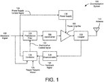
- FIG. 1 shows a diagram of a communication system 100 that adjusts a power supply for a power amplifier to improve the power efficiency of the power amplifier.
- the communication system 100 receives a baseband signal 102 and transmits a wireless signal using the baseband signal 102 via an antenna 112.
- the communication system 100 includes a predistortion filter 104 that receives the baseband signal 102 and predistorts the baseband signal 102 to compensate for distortion to be added by components of the communication system 100.
- the predistorted signal from the predistortion filter 104 is increased in frequency (e.g., upconverted) by the upconverter 106.
- a power amplifier 108 amplifies the upconverted signal from the upconverter 106 and receives power from a power supply 118.
- the amplified signal from the power amplifier 108 is provided to a coupler 110 that provides the amplified signal to the antenna 112 and provides a coupled signal to a downconverter 114.
- the downconverter 114 decreases a frequency of the coupled signal from the coupler 110 to generate a feedback signal 120 that is provided to a controller 116.
- the controller 116 receives a target transmit power 126 in addition to the baseband signal 102 and the feedback signal 120.
- the controller 116 uses the baseband signal 102, the target transmit power 126, and/or the feedback signal 120 to generate a predistortion control signal 122 that controls the predistortion filter 104 and a power supply control signal 124 that controls the power supply 118.
- the predistortion filter 104 filters the baseband signal 102 to generate a predistorted signal.
- the predistortion filter 104 may adjust one or more characteristics of the baseband signal 102 to reduce (or cancel out) distortion to be introduced by components of the communication system 100, such as the power amplifier 108.
- the predistortion filter 104 may adjust, for example, an amplitude and/or a phase of the baseband signal 102.
- the predistortion filter 104 may be a configurable filter that is controlled based on the predistortion control signal 122.
- the predistortion filter 104 may adjust a phase shift and/or an amplitude adjustment applied to the baseband signal 102 based on the predistortion control signal 122 received from the controller 116.
- the upconverter 106 increases a frequency of the predistorted signal received from the predistortion filter 104 to generate an upconverted signal.
- the upconverter 106 may include a mixer that multiplies the predistorted signal with a radio frequency signal to increase a frequency of the predistorted signal.
- the upconverter 106 may increase the frequency of the predistorted signal to a frequency that is in the radio spectrum (e.g., between 3 Hertz and 3000 Gigahertz).
- the power amplifier 108 amplifies the upconverted signal from the upconverter 106 to generate an amplified signal.
- the power amplifier 108 may receive power from the power supply 118.
- the power supply 118 may provide a supply voltage and a supply current to the power amplifier 108.
- the power supply 118 may adjust the supply voltage and/or the supply current provided to the power amplifier 108 based on the power supply control signal 124.
- the coupler 110 receives the amplified signal from the power amplifier 108, provides the amplified signal to the antenna 112, and provides a coupled signal to the downconverter 114.
- the coupled signal may be indicative of the amplified signal and be at a lower power level than the amplified signal.
- the coupler 110 may be constructed to provide a majority of the input power (e.g., more than 50%) from the power amplifier 108 to the antenna 112.
- the portion of the input power provided to the downconverter 114 may be smaller than the portion of the input power provided to the antenna 112.
- the downconverter 114 decreases a frequency of the coupled signal from the coupler 110 to generate the feedback signal 120.
- the downconverter 106 may include a mixer that multiplies the coupled signal with a radio frequency signal to decrease a frequency of the coupled signal.
- the controller 116 controls the power supply 118 to increase a power efficiency of the power amplifier 108 and controls the predistortion filter 104 to reduce (or cancel) distortion introduced by components of the communication system 100.
- the controller 116 may include, for example, a microcontroller (or other suitable processing device) to generate the predistortion control signal 122 and the power supply control signal 124 based on various received and/or determined parameters.
- the controller 116 may adjust the power supply 118 and/or the predistortion filter 104 prior to a wireless transmission based on information regarding the wireless transmission such as a target transmit power 126 for the wireless transmission and/or a peak-to-average power ratio of the baseband signal 102 to be transmitted.
- the controller 116 may include a memory storing information indicative of relationships between the parameters associated with the wireless transmission to be performed and settings for the power supply 118.
- the controller 116 may store the relationship in memory as, for example, a lookup table. In this example, the controller 116 may use these relationships to generate the power supply control signal 124.
- the stored relationships may not be direct relationships between parameters associated with the wireless transmission to be performed and the settings for the power supply 118.
- information indicative of a relationship between the target transmit power 126 and the supply voltage may be a relationship between the target transmit power 126 and a desired amount of voltage headroom that is employed, in turn, to determine the supply voltage.
- the controller 116 may generate performance information when the wireless signal is transmitted and update the relationships stored in memory based on the generated performance information. For example, the controller 116 may identify a voltage level of the output signal of the power amplifier 108 during a transmission based on the feedback signal 120 and also identify the supply voltage provided to the power amplifier 108 during the transmission. In this example, the controller 116 may identify the amount of voltage headroom in the power amplifier 108 by comparing the output voltage of the power amplifier 108 to the supply voltage provided by the power supply 118. The determined amount of voltage headroom may be compared with a desired amount of voltage headroom to determine whether the amount of voltage headroom was above a minimum threshold.
- the controller 116 may increase the supply voltage for the target transmit power level associated with the transmission. Conversely, the controller 116 may decrease the supply voltage for the target transmit power level associated with the transmission in response to the amount of voltage headroom being above the minimum threshold to improve a power efficiency of the power amplifier 108. Thereby, the controller 116 may fine-tune the relationships stored in memory over time to achieve a desired balance between the power efficiency of the power amplifier 108 and distortion in the wireless transmission.
- the controller 116 may only adjust the predistortion filter 104 and/or the power supply 118 during a gap period where the communication system 100 is not transmitting a wireless signal. For example, the controller 116 may determine whether the communication system 100 is transmitting a wireless signal and adjust the power supply 118 and/or the predistortion filter 104 responsive to a determination that a wireless signal is not being transmitted. Otherwise, the controller 116 may wait for the wireless transmission to be completed. Thereby, the controller 116 may reduce the possibility of distorting the wireless transmission by adjusting the communication system 100 during the wireless transmission.
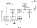
- FIG. 2 shows an example implementation of the controller 116 in the communication system 100.
- the controller 116 includes a power supply controller 204 that generates the power supply control signal 124 to control the power supply 118 and a predistortion controller 202 that generates the predistortion control signal 122 to control the predistortion filter 104.
- the predistortion controller 202 may receive the feedback signal 120 and the baseband signal 102 and generate the predistortion control signal 122. In some embodiments, the predistortion controller 202 determines various characteristics of the baseband signal 102 and/or the amplified signal provided by the power amplifier 108. For example, the predistortion controller 202 may determine a peak-to-average power ratio of the baseband signal 102 using the received baseband signal 102 and/or an output power of the power amplifier 108 using the feedback signal 120. These determined signal characteristics may be employed to generate the predistortion control signal 122. Further, these determined signal characteristics may be provided to the power supply controller 204 for use in the generation of the power supply control signal 124.
- the power supply controller 204 controls the settings of the power supply 118 based on parameters associated with the wireless transmission.
- the controller 116 may use information indicative of various relationships stored in memory (e.g., stored as an LUT in memory) to generate the power supply control signal 124.
- an LUT may be stored in memory and include information indicative of relationships between parameters including the target transmit power 126 and the peak-to-average power ratio of the baseband signal 102 and the supply voltage provided by the power supply 118.
- the power supply controller 204 may receive the target transmit power 126 from another component in the communication system 100 and/or from an external system.
- the power supply controller 204 may receive the peak-to-average power ratio of the baseband signal 102 from the predistortion controller 202. These received parameters may be applied to the LUT to identify the appropriate supply voltage to provide the power amplifier 108.
- the power supply controller 204 may generate the power supply control signal 124 to adjust the supply voltage provided by the power supply 118 to the identified supply voltage.
- the power supply controller 204 may generate performance information when the wireless signal is transmitted and update the relationships stored in memory (e.g., by updating entries in an LUT) using the generated performance information.
- Example performance information that may be generated includes the amount of voltage headroom in the power amplifier 108 when the wireless signal is transmitted and the output power of the power amplifier 108 when the wireless signal is transmitted.
- the power supply controller 204 may determine the amount of voltage headroom in the power amplifier 108 during transmission of the wireless signal based on the feedback signal 120 and the supply voltage setting provided to the power supply 118 during the wireless transmission.
- the power supply controller 204 may compare the determined amount of voltage headroom with a desired amount of voltage headroom (e.g., stored in the LUT).
- the power supply controller 204 may adjust the supply voltage associated with one or more entries in the LUT employed to transmit the wireless signal. It should be appreciated that the power supply controller 204 may also adjust entries proximate the one or more entries in the LUT employed to transmit the wireless signal using interpolation techniques. For example, the power supply controller 204 may have recently updated the power supply settings in a first entry in the LUT for a first target transmit power level and a second entry in the LUT for a second target transmit power level. In this example, the power supply controller 204 may also update the power supply settings in a third entry in the LUT with a third target transmit power level that is between the first and second transmit power levels using interpolation. The controller 116 may also update the power supply settings in a fourth entry in the LUT with a target transmit power level that is outside the first and second transmit power levels using extrapolation.
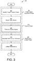
- the method of operation 300 includes a power supply adjustment phase 301 where the settings of the power supply that provides power to the power amplifier is adjusted for the next wireless transmission.
- the power supply adjust phase 301 includes an act 302 of identifying a target transmit power and an act 304 of adjusting the power supply.
- a transmit phase 303 follows the power supply adjustment phase 301 where the communication system transmits the wireless signal.
- the transmit phase 303 includes an act 306 of transmitting the wireless signal.
- a relationship update phase 305 follows the transmit phase 303 where the communication system updates the relationships stored in memory using generated performance information indicative of at least one characteristic of the communication system when the wireless signal is transmitted.
- the relationship update phase 305 includes an act 308 of generating the performance information and act 310 of updating the relationships.
- the communication system identifies a target transmit power level for transmitting a wireless signal.
- the communication system may receive the target transmit power level from an external system.
- the communication system may generate the target transmit power level internally.
- the communication system adjusts the power supply for a power amplifier of the communication system. For example, the communication system may adjust a supply voltage to the power amplifier and/or a supply current to the power amplifier. In some embodiments, the communication system may adjust the power supply based on the identified target transmit power level. In these embodiments, the communication system may determine a setting for the power supply using information indicative of a relationship between the target transmit power level and the settings for the power supply. For example, the relationships may be stored as an LUT that includes a plurality of target transmit power levels and an associated supply voltage and/or supply current setting for the power supply for each of the target transmit power levels.
- the relationships may be stored as an LUT that includes a plurality of target power levels and an associated amount of headroom in the power amplifier for each of the target transmit power levels.
- the identified amount of headroom in the power amplifier from the LUT may be employed, in turn, to determine the supply voltage and/or supply current settings.
- the communication system may adjust the power supply based on additional parameters.
- the communication system may adjust the power supply based on a characteristic of a baseband signal to be transmitted by the communication system such as a peak-to-average power ratio of the baseband signal.
- the LUT may also include a plurality of values for the characteristic of the baseband signal and an associated setting for each characteristic.
- the communication system may adjust the power supply for the power amplifier of the communication system during gap periods when the communication system is not transmitting a wireless signal. Adjusting the power supply during gap periods may advantageously reduce the possibility of distorting the signal being amplified by the power amplifier during transmission.
- the communication system may determine whether the communication system is transmitting a wireless signal and adjust the power supply responsive to a determination that the communication system is not transmitting a wireless signal. Otherwise, the communication system may wait to adjust the power supply until the transmission has been completed.
- the communication system transmits the wireless signal.
- the communication system may receive a baseband signal and transmit a wireless signal based on the received baseband signal.
- the communication system may transmit the wireless signal by receiving a baseband signal to be wirelessly transmitted and predistorting the baseband signal to compensate for distortion to be introduced by the power amplifier.
- the communication system may increase a frequency (e.g., upconvert) the predistorted signal and amplify the predistorted signal using the power amplifier.
- the amplified signal may be provided to an antenna for wireless transmission.
- the communication system generates performance information indicative of at least one characteristics of the communication system during transmission of the wireless signal. For example, the communication system may determine an amount of voltage headroom of the power amplifier and/or an output power of the power amplifier. The communication system may also gather information indicative of various settings associated with the transmission such as the target transmit power level associated with the transmission of the wireless signal and/or the peak-to-average power ratio of the baseband signal used in the transmission.
- the communication system updates the relationships stored in memory using the generated performance information. For example, the communication may update one or more entries in a LUT stored in memory. In some embodiments, the communication system may revise an LUT entry associated with the target transmit power level used during transmission of the wireless signal. For example, an entry in an LUT may include a supply voltage setting associated with a given target transmit power level to achieve a minimum amount of voltage headroom. In this example, the communication system may determine whether the amount of voltage headroom in the generated performance information exceeded the minimum amount of voltage headroom. If the communication system determines that the amount of voltage headroom was less than the predetermined amount of voltage headroom, the communication system may revise the entry to increase a supply voltage of the power amplifier. Conversely, the communication system may revise the entry to decrease the supply voltage if the communication system determines that the amount of voltage headroom was more than the predetermined amount of voltage headroom.
Landscapes
- Engineering & Computer Science (AREA)
- Power Engineering (AREA)
- Computer Networks & Wireless Communication (AREA)
- Signal Processing (AREA)
- Physics & Mathematics (AREA)
- Nonlinear Science (AREA)
- Amplifiers (AREA)
- Transmitters (AREA)
Applications Claiming Priority (3)
| Application Number | Priority Date | Filing Date | Title |
|---|---|---|---|
| US201662287484P | 2016-01-27 | 2016-01-27 | |
| US201662313160P | 2016-03-25 | 2016-03-25 | |
| US15/374,992 US9985590B2 (en) | 2016-01-27 | 2016-12-09 | Adaptive power amplifier supply with pre-distortion mechanism |
Publications (2)
| Publication Number | Publication Date |
|---|---|
| EP3200344A1 true EP3200344A1 (de) | 2017-08-02 |
| EP3200344B1 EP3200344B1 (de) | 2018-12-05 |
Family
ID=57906580
Family Applications (1)
| Application Number | Title | Priority Date | Filing Date |
|---|---|---|---|
| EP17153402.7A Active EP3200344B1 (de) | 2016-01-27 | 2017-01-26 | Adaptive leistungsverstärkerversorgung mit vorverzerrungsmechanismus |
Country Status (3)
| Country | Link |
|---|---|
| US (1) | US9985590B2 (de) |
| EP (1) | EP3200344B1 (de) |
| CN (1) | CN107040267A (de) |
Families Citing this family (7)
| Publication number | Priority date | Publication date | Assignee | Title |
|---|---|---|---|---|
| WO2014109782A1 (en) | 2013-01-14 | 2014-07-17 | Andrew Llc | Interceptor system for characterizing digital data in telecommunication system |
| US10608919B2 (en) | 2016-02-19 | 2020-03-31 | Commscope Technologies Llc | Passive intermodulation (PIM) testing in distributed base transceiver station architecture |
| US10609582B2 (en) * | 2016-09-08 | 2020-03-31 | Commscope Technologies Llc | Interference detection and identification in wireless network from RF or digitized signal |
| US11228281B2 (en) | 2018-07-17 | 2022-01-18 | Mediatek Inc. | Apparatus and method for calibrating characteristics of power amplifier in transmitter |
| JP2021106306A (ja) * | 2019-12-26 | 2021-07-26 | 株式会社東芝 | 電子装置及び方法 |
| DE102021208318B4 (de) * | 2021-07-30 | 2023-02-16 | Fraunhofer-Gesellschaft zur Förderung der angewandten Forschung eingetragener Verein | Schaltung und Verfahren zur Kompensation von Nichtlinearitäten |
| KR20250139271A (ko) * | 2023-01-30 | 2025-09-23 | 코르보 유에스, 인크. | 프론트엔드 모듈의 피크 대 평균 전력비(par) 기반 아날로그 전치왜곡(apd) |
Citations (3)
| Publication number | Priority date | Publication date | Assignee | Title |
|---|---|---|---|---|
| US20100105343A1 (en) * | 2008-10-28 | 2010-04-29 | Freescale Semiconductor, Inc. | Systems and methods for adjusting headroom of a power amplifier |
| US20130257529A1 (en) * | 2011-09-16 | 2013-10-03 | Qualcomm Incorporated | Circuitry for reducing power consumption |
| US20150145600A1 (en) * | 2013-11-22 | 2015-05-28 | Qualcomm Incorporated | Circuits and methods for power amplification with extended high efficiency |
Family Cites Families (7)
| Publication number | Priority date | Publication date | Assignee | Title |
|---|---|---|---|---|
| EP0885482B1 (de) | 1996-06-19 | 1999-08-04 | Fraunhofer-Gesellschaft Zur Förderung Der Angewandten Forschung E.V. | Vorverzerrung für eine nichtlineare übertragungsstrecke im hochfrequenzbereich |
| US6703897B2 (en) | 2001-12-26 | 2004-03-09 | Nortel Networks Limited | Methods of optimising power amplifier efficiency and closed-loop power amplifier controllers |
| US7091777B2 (en) | 2002-09-30 | 2006-08-15 | Lucent Technologies Inc. | Controller for an RF power amplifier |
| US7026868B2 (en) | 2003-11-20 | 2006-04-11 | Northrop Grumman Corporation | Variable supply amplifier system |
| US9369094B2 (en) * | 2010-10-20 | 2016-06-14 | Aviat U.S., Inc. | Systems and methods for improved power yield and linerization in radio frequency transmitters |
| US9042848B2 (en) * | 2012-12-19 | 2015-05-26 | Mediatek Singapore Pte. Ltd. | Method and apparatus for calibrating an envelope tracking system |
| US9654154B2 (en) * | 2014-09-08 | 2017-05-16 | Apple Inc. | Radio frequency adaptive voltage shaping power amplifier systems and methods |
-
2016
- 2016-12-09 US US15/374,992 patent/US9985590B2/en active Active
-
2017
- 2017-01-25 CN CN201710060640.5A patent/CN107040267A/zh not_active Withdrawn
- 2017-01-26 EP EP17153402.7A patent/EP3200344B1/de active Active
Patent Citations (3)
| Publication number | Priority date | Publication date | Assignee | Title |
|---|---|---|---|---|
| US20100105343A1 (en) * | 2008-10-28 | 2010-04-29 | Freescale Semiconductor, Inc. | Systems and methods for adjusting headroom of a power amplifier |
| US20130257529A1 (en) * | 2011-09-16 | 2013-10-03 | Qualcomm Incorporated | Circuitry for reducing power consumption |
| US20150145600A1 (en) * | 2013-11-22 | 2015-05-28 | Qualcomm Incorporated | Circuits and methods for power amplification with extended high efficiency |
Also Published As
| Publication number | Publication date |
|---|---|
| US9985590B2 (en) | 2018-05-29 |
| US20170214370A1 (en) | 2017-07-27 |
| EP3200344B1 (de) | 2018-12-05 |
| CN107040267A (zh) | 2017-08-11 |
Similar Documents
| Publication | Publication Date | Title |
|---|---|---|
| US9985590B2 (en) | Adaptive power amplifier supply with pre-distortion mechanism | |
| US8626091B2 (en) | Envelope tracking with variable compression | |
| US10153794B2 (en) | Transmitter, communication unit and method for limiting spectral re-growth | |
| US10447222B2 (en) | Dynamic thermal compensation in a power amplifier | |
| US9998241B2 (en) | Envelope tracking (ET) closed-loop on-the-fly calibration | |
| CN105103443B (zh) | 具有内部功率放大器特征化的包络跟踪系统 | |
| US10855232B2 (en) | Power amplifier module | |
| JP4935906B2 (ja) | 歪補償装置および方法 | |
| KR20210068071A (ko) | 푸시-풀 전력 증폭기들을 위한 부하선 스위칭 | |
| US12063018B2 (en) | Envelope tracking integrated circuit operable with multiple types of power amplifiers | |
| US9735811B2 (en) | Digital predistortion of non-linear devices | |
| WO2014152876A1 (en) | Noise conversion gain limited rf power amplifier | |
| JP2007514370A (ja) | 適応送信電力制御システム | |
| EP3771095B1 (de) | Elektronische vorrichtung und drahtloskommunikationssystem dafür | |
| JP4641715B2 (ja) | 歪補償装置及び無線基地局 | |
| JP4583979B2 (ja) | 送信装置及び無線通信装置 | |
| US20150017931A1 (en) | System and method for controlling envelope tracking in a transmitter with closed loop power control | |
| US8442459B2 (en) | Transmitter and communication apparatus using the same | |
| JP3874747B2 (ja) | 送信装置、送信電力制御方法および無線通信装置 | |
| US11005517B2 (en) | Handling of unwanted emissions from a radio communications device | |
| US7729671B2 (en) | Method and system for enhancing efficiency by modulating power amplifier gain | |
| US10075310B2 (en) | Adaptive linearizer | |
| EP2824978B1 (de) | System und Verfahren zur Steuerung der Hüllkurvenverfolgung in einem Sender mit geschlossener Leistungsregelung | |
| US20080136515A1 (en) | Method and System for Enhancement of Power Amplifier Efficiency Through Controlled Variation of Gain in a Power Amplifier Driver | |
| TW202320519A (zh) | 具有輸出功率補償機制的傳送電路及其操作方法 |
Legal Events
| Date | Code | Title | Description |
|---|---|---|---|
| PUAI | Public reference made under article 153(3) epc to a published international application that has entered the european phase |
Free format text: ORIGINAL CODE: 0009012 |
|
| STAA | Information on the status of an ep patent application or granted ep patent |
Free format text: STATUS: THE APPLICATION HAS BEEN PUBLISHED |
|
| AK | Designated contracting states |
Kind code of ref document: A1 Designated state(s): AL AT BE BG CH CY CZ DE DK EE ES FI FR GB GR HR HU IE IS IT LI LT LU LV MC MK MT NL NO PL PT RO RS SE SI SK SM TR |
|
| AX | Request for extension of the european patent |
Extension state: BA ME |
|
| STAA | Information on the status of an ep patent application or granted ep patent |
Free format text: STATUS: REQUEST FOR EXAMINATION WAS MADE |
|
| 17P | Request for examination filed |
Effective date: 20180202 |
|
| RBV | Designated contracting states (corrected) |
Designated state(s): AL AT BE BG CH CY CZ DE DK EE ES FI FR GB GR HR HU IE IS IT LI LT LU LV MC MK MT NL NO PL PT RO RS SE SI SK SM TR |
|
| STAA | Information on the status of an ep patent application or granted ep patent |
Free format text: STATUS: EXAMINATION IS IN PROGRESS |
|
| 17Q | First examination report despatched |
Effective date: 20180412 |
|
| GRAP | Despatch of communication of intention to grant a patent |
Free format text: ORIGINAL CODE: EPIDOSNIGR1 |
|
| STAA | Information on the status of an ep patent application or granted ep patent |
Free format text: STATUS: GRANT OF PATENT IS INTENDED |
|
| INTG | Intention to grant announced |
Effective date: 20180612 |
|
| GRAS | Grant fee paid |
Free format text: ORIGINAL CODE: EPIDOSNIGR3 |
|
| GRAA | (expected) grant |
Free format text: ORIGINAL CODE: 0009210 |
|
| STAA | Information on the status of an ep patent application or granted ep patent |
Free format text: STATUS: THE PATENT HAS BEEN GRANTED |
|
| AK | Designated contracting states |
Kind code of ref document: B1 Designated state(s): AL AT BE BG CH CY CZ DE DK EE ES FI FR GB GR HR HU IE IS IT LI LT LU LV MC MK MT NL NO PL PT RO RS SE SI SK SM TR |
|
| REG | Reference to a national code |
Ref country code: GB Ref legal event code: FG4D |
|
| REG | Reference to a national code |
Ref country code: CH Ref legal event code: EP |
|
| REG | Reference to a national code |
Ref country code: AT Ref legal event code: REF Ref document number: 1074329 Country of ref document: AT Kind code of ref document: T Effective date: 20181215 |
|
| REG | Reference to a national code |
Ref country code: IE Ref legal event code: FG4D |
|
| REG | Reference to a national code |
Ref country code: DE Ref legal event code: R096 Ref document number: 602017001109 Country of ref document: DE |
|
| REG | Reference to a national code |
Ref country code: NL Ref legal event code: MP Effective date: 20181205 |
|
| REG | Reference to a national code |
Ref country code: AT Ref legal event code: MK05 Ref document number: 1074329 Country of ref document: AT Kind code of ref document: T Effective date: 20181205 |
|
| REG | Reference to a national code |
Ref country code: LT Ref legal event code: MG4D |
|
| PG25 | Lapsed in a contracting state [announced via postgrant information from national office to epo] |
Ref country code: LV Free format text: LAPSE BECAUSE OF FAILURE TO SUBMIT A TRANSLATION OF THE DESCRIPTION OR TO PAY THE FEE WITHIN THE PRESCRIBED TIME-LIMIT Effective date: 20181205 Ref country code: ES Free format text: LAPSE BECAUSE OF FAILURE TO SUBMIT A TRANSLATION OF THE DESCRIPTION OR TO PAY THE FEE WITHIN THE PRESCRIBED TIME-LIMIT Effective date: 20181205 Ref country code: NO Free format text: LAPSE BECAUSE OF FAILURE TO SUBMIT A TRANSLATION OF THE DESCRIPTION OR TO PAY THE FEE WITHIN THE PRESCRIBED TIME-LIMIT Effective date: 20190305 Ref country code: AT Free format text: LAPSE BECAUSE OF FAILURE TO SUBMIT A TRANSLATION OF THE DESCRIPTION OR TO PAY THE FEE WITHIN THE PRESCRIBED TIME-LIMIT Effective date: 20181205 Ref country code: FI Free format text: LAPSE BECAUSE OF FAILURE TO SUBMIT A TRANSLATION OF THE DESCRIPTION OR TO PAY THE FEE WITHIN THE PRESCRIBED TIME-LIMIT Effective date: 20181205 Ref country code: LT Free format text: LAPSE BECAUSE OF FAILURE TO SUBMIT A TRANSLATION OF THE DESCRIPTION OR TO PAY THE FEE WITHIN THE PRESCRIBED TIME-LIMIT Effective date: 20181205 Ref country code: BG Free format text: LAPSE BECAUSE OF FAILURE TO SUBMIT A TRANSLATION OF THE DESCRIPTION OR TO PAY THE FEE WITHIN THE PRESCRIBED TIME-LIMIT Effective date: 20190305 Ref country code: HR Free format text: LAPSE BECAUSE OF FAILURE TO SUBMIT A TRANSLATION OF THE DESCRIPTION OR TO PAY THE FEE WITHIN THE PRESCRIBED TIME-LIMIT Effective date: 20181205 |
|
| PG25 | Lapsed in a contracting state [announced via postgrant information from national office to epo] |
Ref country code: GR Free format text: LAPSE BECAUSE OF FAILURE TO SUBMIT A TRANSLATION OF THE DESCRIPTION OR TO PAY THE FEE WITHIN THE PRESCRIBED TIME-LIMIT Effective date: 20190306 Ref country code: RS Free format text: LAPSE BECAUSE OF FAILURE TO SUBMIT A TRANSLATION OF THE DESCRIPTION OR TO PAY THE FEE WITHIN THE PRESCRIBED TIME-LIMIT Effective date: 20181205 Ref country code: SE Free format text: LAPSE BECAUSE OF FAILURE TO SUBMIT A TRANSLATION OF THE DESCRIPTION OR TO PAY THE FEE WITHIN THE PRESCRIBED TIME-LIMIT Effective date: 20181205 Ref country code: AL Free format text: LAPSE BECAUSE OF FAILURE TO SUBMIT A TRANSLATION OF THE DESCRIPTION OR TO PAY THE FEE WITHIN THE PRESCRIBED TIME-LIMIT Effective date: 20181205 |
|
| PG25 | Lapsed in a contracting state [announced via postgrant information from national office to epo] |
Ref country code: NL Free format text: LAPSE BECAUSE OF FAILURE TO SUBMIT A TRANSLATION OF THE DESCRIPTION OR TO PAY THE FEE WITHIN THE PRESCRIBED TIME-LIMIT Effective date: 20181205 |
|
| PG25 | Lapsed in a contracting state [announced via postgrant information from national office to epo] |
Ref country code: PL Free format text: LAPSE BECAUSE OF FAILURE TO SUBMIT A TRANSLATION OF THE DESCRIPTION OR TO PAY THE FEE WITHIN THE PRESCRIBED TIME-LIMIT Effective date: 20181205 Ref country code: IT Free format text: LAPSE BECAUSE OF FAILURE TO SUBMIT A TRANSLATION OF THE DESCRIPTION OR TO PAY THE FEE WITHIN THE PRESCRIBED TIME-LIMIT Effective date: 20181205 Ref country code: CZ Free format text: LAPSE BECAUSE OF FAILURE TO SUBMIT A TRANSLATION OF THE DESCRIPTION OR TO PAY THE FEE WITHIN THE PRESCRIBED TIME-LIMIT Effective date: 20181205 Ref country code: PT Free format text: LAPSE BECAUSE OF FAILURE TO SUBMIT A TRANSLATION OF THE DESCRIPTION OR TO PAY THE FEE WITHIN THE PRESCRIBED TIME-LIMIT Effective date: 20190405 |
|
| PG25 | Lapsed in a contracting state [announced via postgrant information from national office to epo] |
Ref country code: RO Free format text: LAPSE BECAUSE OF FAILURE TO SUBMIT A TRANSLATION OF THE DESCRIPTION OR TO PAY THE FEE WITHIN THE PRESCRIBED TIME-LIMIT Effective date: 20181205 Ref country code: SM Free format text: LAPSE BECAUSE OF FAILURE TO SUBMIT A TRANSLATION OF THE DESCRIPTION OR TO PAY THE FEE WITHIN THE PRESCRIBED TIME-LIMIT Effective date: 20181205 Ref country code: IS Free format text: LAPSE BECAUSE OF FAILURE TO SUBMIT A TRANSLATION OF THE DESCRIPTION OR TO PAY THE FEE WITHIN THE PRESCRIBED TIME-LIMIT Effective date: 20190405 Ref country code: EE Free format text: LAPSE BECAUSE OF FAILURE TO SUBMIT A TRANSLATION OF THE DESCRIPTION OR TO PAY THE FEE WITHIN THE PRESCRIBED TIME-LIMIT Effective date: 20181205 Ref country code: SK Free format text: LAPSE BECAUSE OF FAILURE TO SUBMIT A TRANSLATION OF THE DESCRIPTION OR TO PAY THE FEE WITHIN THE PRESCRIBED TIME-LIMIT Effective date: 20181205 |
|
| REG | Reference to a national code |
Ref country code: DE Ref legal event code: R097 Ref document number: 602017001109 Country of ref document: DE |
|
| PG25 | Lapsed in a contracting state [announced via postgrant information from national office to epo] |
Ref country code: LU Free format text: LAPSE BECAUSE OF NON-PAYMENT OF DUE FEES Effective date: 20190126 |
|
| PLBE | No opposition filed within time limit |
Free format text: ORIGINAL CODE: 0009261 |
|
| STAA | Information on the status of an ep patent application or granted ep patent |
Free format text: STATUS: NO OPPOSITION FILED WITHIN TIME LIMIT |
|
| REG | Reference to a national code |
Ref country code: BE Ref legal event code: MM Effective date: 20190131 |
|
| REG | Reference to a national code |
Ref country code: IE Ref legal event code: MM4A |
|
| PG25 | Lapsed in a contracting state [announced via postgrant information from national office to epo] |
Ref country code: SI Free format text: LAPSE BECAUSE OF FAILURE TO SUBMIT A TRANSLATION OF THE DESCRIPTION OR TO PAY THE FEE WITHIN THE PRESCRIBED TIME-LIMIT Effective date: 20181205 Ref country code: MC Free format text: LAPSE BECAUSE OF FAILURE TO SUBMIT A TRANSLATION OF THE DESCRIPTION OR TO PAY THE FEE WITHIN THE PRESCRIBED TIME-LIMIT Effective date: 20181205 Ref country code: DK Free format text: LAPSE BECAUSE OF FAILURE TO SUBMIT A TRANSLATION OF THE DESCRIPTION OR TO PAY THE FEE WITHIN THE PRESCRIBED TIME-LIMIT Effective date: 20181205 |
|
| 26N | No opposition filed |
Effective date: 20190906 |
|
| PG25 | Lapsed in a contracting state [announced via postgrant information from national office to epo] |
Ref country code: BE Free format text: LAPSE BECAUSE OF NON-PAYMENT OF DUE FEES Effective date: 20190131 |
|
| PG25 | Lapsed in a contracting state [announced via postgrant information from national office to epo] |
Ref country code: IE Free format text: LAPSE BECAUSE OF NON-PAYMENT OF DUE FEES Effective date: 20190126 |
|
| PG25 | Lapsed in a contracting state [announced via postgrant information from national office to epo] |
Ref country code: TR Free format text: LAPSE BECAUSE OF FAILURE TO SUBMIT A TRANSLATION OF THE DESCRIPTION OR TO PAY THE FEE WITHIN THE PRESCRIBED TIME-LIMIT Effective date: 20181205 |
|
| PG25 | Lapsed in a contracting state [announced via postgrant information from national office to epo] |
Ref country code: MT Free format text: LAPSE BECAUSE OF NON-PAYMENT OF DUE FEES Effective date: 20190126 |
|
| REG | Reference to a national code |
Ref country code: CH Ref legal event code: PL |
|
| PG25 | Lapsed in a contracting state [announced via postgrant information from national office to epo] |
Ref country code: CH Free format text: LAPSE BECAUSE OF NON-PAYMENT OF DUE FEES Effective date: 20200131 Ref country code: LI Free format text: LAPSE BECAUSE OF NON-PAYMENT OF DUE FEES Effective date: 20200131 |
|
| PG25 | Lapsed in a contracting state [announced via postgrant information from national office to epo] |
Ref country code: CY Free format text: LAPSE BECAUSE OF FAILURE TO SUBMIT A TRANSLATION OF THE DESCRIPTION OR TO PAY THE FEE WITHIN THE PRESCRIBED TIME-LIMIT Effective date: 20181205 |
|
| PG25 | Lapsed in a contracting state [announced via postgrant information from national office to epo] |
Ref country code: HU Free format text: LAPSE BECAUSE OF FAILURE TO SUBMIT A TRANSLATION OF THE DESCRIPTION OR TO PAY THE FEE WITHIN THE PRESCRIBED TIME-LIMIT; INVALID AB INITIO Effective date: 20170126 |
|
| PG25 | Lapsed in a contracting state [announced via postgrant information from national office to epo] |
Ref country code: MK Free format text: LAPSE BECAUSE OF FAILURE TO SUBMIT A TRANSLATION OF THE DESCRIPTION OR TO PAY THE FEE WITHIN THE PRESCRIBED TIME-LIMIT Effective date: 20181205 |
|
| P01 | Opt-out of the competence of the unified patent court (upc) registered |
Effective date: 20230607 |
|
| PGFP | Annual fee paid to national office [announced via postgrant information from national office to epo] |
Ref country code: DE Payment date: 20250129 Year of fee payment: 9 |
|
| PGFP | Annual fee paid to national office [announced via postgrant information from national office to epo] |
Ref country code: GB Payment date: 20251204 Year of fee payment: 10 |
|
| PGFP | Annual fee paid to national office [announced via postgrant information from national office to epo] |
Ref country code: FR Payment date: 20251128 Year of fee payment: 10 |