EP3200077A1 - Vehicle control device, reprogramming system - Google Patents
Vehicle control device, reprogramming system Download PDFInfo
- Publication number
- EP3200077A1 EP3200077A1 EP15844264.0A EP15844264A EP3200077A1 EP 3200077 A1 EP3200077 A1 EP 3200077A1 EP 15844264 A EP15844264 A EP 15844264A EP 3200077 A1 EP3200077 A1 EP 3200077A1
- Authority
- EP
- European Patent Office
- Prior art keywords
- control program
- storage unit
- vehicle control
- updated version
- storage
- Prior art date
- Legal status (The legal status is an assumption and is not a legal conclusion. Google has not performed a legal analysis and makes no representation as to the accuracy of the status listed.)
- Granted
Links
- 230000008672 reprogramming Effects 0.000 title claims description 66
- 238000012545 processing Methods 0.000 claims description 21
- 238000000034 method Methods 0.000 claims description 9
- 238000004891 communication Methods 0.000 claims description 3
- 238000010586 diagram Methods 0.000 description 12
- 230000006870 function Effects 0.000 description 4
- 230000004044 response Effects 0.000 description 3
- 230000000694 effects Effects 0.000 description 2
- 238000012423 maintenance Methods 0.000 description 2
- 238000012986 modification Methods 0.000 description 2
- 230000004048 modification Effects 0.000 description 2
- 230000002093 peripheral effect Effects 0.000 description 2
- 238000003672 processing method Methods 0.000 description 1
- 239000007787 solid Substances 0.000 description 1
Images


Classifications
-
- G—PHYSICS
- G06—COMPUTING; CALCULATING OR COUNTING
- G06F—ELECTRIC DIGITAL DATA PROCESSING
- G06F9/00—Arrangements for program control, e.g. control units
- G06F9/06—Arrangements for program control, e.g. control units using stored programs, i.e. using an internal store of processing equipment to receive or retain programs
- G06F9/44—Arrangements for executing specific programs
- G06F9/445—Program loading or initiating
-
- G—PHYSICS
- G06—COMPUTING; CALCULATING OR COUNTING
- G06F—ELECTRIC DIGITAL DATA PROCESSING
- G06F8/00—Arrangements for software engineering
- G06F8/60—Software deployment
- G06F8/65—Updates
- G06F8/654—Updates using techniques specially adapted for alterable solid state memories, e.g. for EEPROM or flash memories
-
- B—PERFORMING OPERATIONS; TRANSPORTING
- B60—VEHICLES IN GENERAL
- B60R—VEHICLES, VEHICLE FITTINGS, OR VEHICLE PARTS, NOT OTHERWISE PROVIDED FOR
- B60R16/00—Electric or fluid circuits specially adapted for vehicles and not otherwise provided for; Arrangement of elements of electric or fluid circuits specially adapted for vehicles and not otherwise provided for
- B60R16/02—Electric or fluid circuits specially adapted for vehicles and not otherwise provided for; Arrangement of elements of electric or fluid circuits specially adapted for vehicles and not otherwise provided for electric constitutive elements
- B60R16/023—Electric or fluid circuits specially adapted for vehicles and not otherwise provided for; Arrangement of elements of electric or fluid circuits specially adapted for vehicles and not otherwise provided for electric constitutive elements for transmission of signals between vehicle parts or subsystems
- B60R16/0231—Circuits relating to the driving or the functioning of the vehicle
-
- B—PERFORMING OPERATIONS; TRANSPORTING
- B60—VEHICLES IN GENERAL
- B60W—CONJOINT CONTROL OF VEHICLE SUB-UNITS OF DIFFERENT TYPE OR DIFFERENT FUNCTION; CONTROL SYSTEMS SPECIALLY ADAPTED FOR HYBRID VEHICLES; ROAD VEHICLE DRIVE CONTROL SYSTEMS FOR PURPOSES NOT RELATED TO THE CONTROL OF A PARTICULAR SUB-UNIT
- B60W50/00—Details of control systems for road vehicle drive control not related to the control of a particular sub-unit, e.g. process diagnostic or vehicle driver interfaces
-
- G—PHYSICS
- G05—CONTROLLING; REGULATING
- G05D—SYSTEMS FOR CONTROLLING OR REGULATING NON-ELECTRIC VARIABLES
- G05D1/00—Control of position, course or altitude of land, water, air, or space vehicles, e.g. automatic pilot
- G05D1/0088—Control of position, course or altitude of land, water, air, or space vehicles, e.g. automatic pilot characterized by the autonomous decision making process, e.g. artificial intelligence, predefined behaviours
-
- G—PHYSICS
- G06—COMPUTING; CALCULATING OR COUNTING
- G06F—ELECTRIC DIGITAL DATA PROCESSING
- G06F11/00—Error detection; Error correction; Monitoring
-
- G—PHYSICS
- G06—COMPUTING; CALCULATING OR COUNTING
- G06F—ELECTRIC DIGITAL DATA PROCESSING
- G06F11/00—Error detection; Error correction; Monitoring
- G06F11/22—Detection or location of defective computer hardware by testing during standby operation or during idle time, e.g. start-up testing
-
- B—PERFORMING OPERATIONS; TRANSPORTING
- B60—VEHICLES IN GENERAL
- B60W—CONJOINT CONTROL OF VEHICLE SUB-UNITS OF DIFFERENT TYPE OR DIFFERENT FUNCTION; CONTROL SYSTEMS SPECIALLY ADAPTED FOR HYBRID VEHICLES; ROAD VEHICLE DRIVE CONTROL SYSTEMS FOR PURPOSES NOT RELATED TO THE CONTROL OF A PARTICULAR SUB-UNIT
- B60W50/00—Details of control systems for road vehicle drive control not related to the control of a particular sub-unit, e.g. process diagnostic or vehicle driver interfaces
- B60W2050/0001—Details of the control system
- B60W2050/0002—Automatic control, details of type of controller or control system architecture
- B60W2050/0004—In digital systems, e.g. discrete-time systems involving sampling
- B60W2050/0005—Processor details or data handling, e.g. memory registers or chip architecture
-
- B—PERFORMING OPERATIONS; TRANSPORTING
- B60—VEHICLES IN GENERAL
- B60W—CONJOINT CONTROL OF VEHICLE SUB-UNITS OF DIFFERENT TYPE OR DIFFERENT FUNCTION; CONTROL SYSTEMS SPECIALLY ADAPTED FOR HYBRID VEHICLES; ROAD VEHICLE DRIVE CONTROL SYSTEMS FOR PURPOSES NOT RELATED TO THE CONTROL OF A PARTICULAR SUB-UNIT
- B60W50/00—Details of control systems for road vehicle drive control not related to the control of a particular sub-unit, e.g. process diagnostic or vehicle driver interfaces
- B60W2050/0001—Details of the control system
- B60W2050/0002—Automatic control, details of type of controller or control system architecture
- B60W2050/0014—Adaptive controllers
-
- B—PERFORMING OPERATIONS; TRANSPORTING
- B60—VEHICLES IN GENERAL
- B60W—CONJOINT CONTROL OF VEHICLE SUB-UNITS OF DIFFERENT TYPE OR DIFFERENT FUNCTION; CONTROL SYSTEMS SPECIALLY ADAPTED FOR HYBRID VEHICLES; ROAD VEHICLE DRIVE CONTROL SYSTEMS FOR PURPOSES NOT RELATED TO THE CONTROL OF A PARTICULAR SUB-UNIT
- B60W50/00—Details of control systems for road vehicle drive control not related to the control of a particular sub-unit, e.g. process diagnostic or vehicle driver interfaces
- B60W2050/0001—Details of the control system
- B60W2050/0019—Control system elements or transfer functions
- B60W2050/0028—Mathematical models, e.g. for simulation
- B60W2050/0031—Mathematical model of the vehicle
- B60W2050/0036—Multiple-track, 3D multi-body vehicle model, e.g. combination of models for vehicle sub-units
-
- B—PERFORMING OPERATIONS; TRANSPORTING
- B60—VEHICLES IN GENERAL
- B60W—CONJOINT CONTROL OF VEHICLE SUB-UNITS OF DIFFERENT TYPE OR DIFFERENT FUNCTION; CONTROL SYSTEMS SPECIALLY ADAPTED FOR HYBRID VEHICLES; ROAD VEHICLE DRIVE CONTROL SYSTEMS FOR PURPOSES NOT RELATED TO THE CONTROL OF A PARTICULAR SUB-UNIT
- B60W50/00—Details of control systems for road vehicle drive control not related to the control of a particular sub-unit, e.g. process diagnostic or vehicle driver interfaces
- B60W2050/0062—Adapting control system settings
- B60W2050/0063—Manual parameter input, manual setting means, manual initialising or calibrating means
- B60W2050/0065—Manual parameter input, manual setting means, manual initialising or calibrating means using a personalised data carrier, e.g. magnetic card, memory card or electronic ignition key
Definitions
- the present invention relates to a vehicle control device.
- a vehicle control device includes an operation device for executing a control program which implements an operation to control a vehicle (for example, microcomputer) and a storage device such as a flash read only memory (ROM) for storing the control program.
- the control program is rewritten into an updated version, for example, by connecting a reprogramming device to the vehicle during a maintenance work and transmitting the updated version of the control program from the reprogramming device to the vehicle control device via an in-vehicle network.
- PTL 1 discloses a technique for rewriting control software of an automobile control unit in a short time.
- a vehicle control device uses a storage device such as a flash ROM. It is necessary to initialize a storage region in which old data is stored before data is updated. The initialization processing takes relatively long time in general. When the control program is stored in the above storage device, it is necessary to perform processing for initializing the storage region, in which the old program is stored, before the control program is updated. Therefore, this causes a long updating work.
- the shorter rewriting of control program is enabled by providing a main storage area for storing a current version of the control program and a sub storage area for storing the updated version in a nonvolatile memory.
- time required to initialize the storage region is not considered.
- the present invention has been made to solve the above problems, and a purpose of the present invention is to provide a vehicle control device which can reduce time required to rewrite a control program.
- a first storage unit is initialized in advance before the instruction to update the control program has been executed.
- processing for initializing a storage unit is separated from processing for rewriting a control program, and a storage region where an old control program is stored is initialized until the next update. Therefore, rewrite processing can be completed in a short time.
- FIG. 1 is a diagram of a configuration of a vehicle control device 1 according to a first embodiment of the present invention.
- the vehicle control device 1 executes a control program which controls an operation of a vehicle.
- an ignition 3 included in the vehicle is turned ON, power is supplied to the vehicle control device 1 via a power circuit 4.
- the vehicle control device 1 is connected to a reprogramming device 2 via an in-vehicle network 5.
- the reprogramming device 2 rewrites the control program executed by the vehicle control device 1 to an updated version. For example, an operator connects the reprogramming device 2 to the vehicle during a maintenance work. The operator transmits an update instruction (reprogramming instruction) of the control program and the updated version to the vehicle control device 1 by operating the reprogramming device 2.
- an update instruction reprogramming instruction
- the vehicle control device 1 includes an operation unit 11 and a storage device 12.
- the operation unit 11 is an operation device such as a microcomputer which executes the control program stored in the storage device 12.
- the operation unit 11 actually executes the programs.
- the storage device 12 is a nonvolatile storage device such as a flash ROM and stores a startup program 121, a rewriting program 122, and management data 123.
- the storage device 12 further includes a first area 124 and a second area 125.
- the startup program 121 is executed by the operation unit 11 at the beginning when the vehicle control device 1 is started in a normal mode.
- the rewriting program 122 rewrites the control program stored in the first area 124 or the second area 125 to the updated version according to an instruction from the reprogramming device 2.
- the management data 123 is described below.
- the first area 124 and the second area 125 are storage regions where the control program is stored. In a state illustrated in FIG. 1 , it is assumed that the first area 124 store a current version of the control program and the second area 125 be empty.
- FIG. 2 is a diagram of a structure of the management data 123.
- the management data 123 holds an unused area number 1231, an unused area head address 1232, an unused area size 1233, and an unused area erased state 1234.
- the unused area number 1231 holds information indicating which of the first area 124 or the second area 125 stores the current version of the control program.
- the unused area head address 1232 and the unused area size 1233 respectively hold a head address and an area size of one of the first area 124 or the second area 125 which does not store the current version of the control program.
- the unused area erased state 1234 holds information indicating whether one of the first area 124 or the second area 125 which does not store the current version of the control program has been completely initialized. A reason for interruption of the initialization is described below.
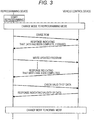
- FIG. 3 is a diagram of a traditional reprogramming sequence. FIG. 3 is illustrated for comparison with the present invention. A problem in the traditional reprogramming sequence is described below with reference to FIG. 3 .
- the operator turns ON the power source (for example, the ignition 3) of the vehicle control device 1. After that, the operator connects the reprogramming device 2 to the vehicle and starts reprogramming (processing for updating the control program).
- the reprogramming device 2 issues a command that instructs the vehicle control device 1 to update control programming.
- a mode of the operation unit 11 is changed to a reprogramming mode.
- the reprogramming device 2 instructs the vehicle control device 1 to erase the old data stored in a ROM area where the control program is stored.
- the operation unit 11 erases the data in the ROM area according to the instruction. When the data in the ROM area is completely erased, the operation unit 11 issues a response indicating that.
- the reprogramming device 2 transmits the updated version of the control program to the vehicle control device 1, and the operation unit 11 writes the updated version to the ROM area in which the data has been erased.
- both the reprogramming device 2 and the vehicle control device 1 check the validity of the written data. When the validity of the written control program is confirmed, the operation unit 11 ends the reprogramming mode and changes its mode to the normal mode.
- the initialization processing takes relatively long time.
- FIG. 4 is a diagram of a sequence to perform the reprogramming by the vehicle control device 1 according to the first embodiment.
- the reprogramming sequence according to the first embodiment is described below with reference to FIG. 4 .
- the operator starts reprogramming as in the traditional reprogramming sequence.
- the reprogramming device 2 inquires of the vehicle control device 1 about the unused area of the storage device 12 (area where the current version of the control program is not stored, and in addition, where the initialization of the storage region has been completed).
- the operation unit 11 makes a response about which one of the first area 124 or the second area 125 is unused with reference to the management data 123 together with the unused area head address 1232 and the unused area size 1233.
- the reprogramming device 2 instructs the vehicle control device 1 to write the updated version of the control program to the unused area.
- the rewriting program 122 writes the updated version of the control program (to the second area 125 in FIG. 1 ) according to the instruction from the reprogramming device 2. After that, until the mode is changed to the normal mode, the operation is the same as that in the traditional sequence described in FIG. 3 .
- the rewriting program 122 since the rewriting program 122 writes the updated version of the control program to the unused area (here, initialized second area 125), it is not necessary to initialize that area before the writing. Therefore, the reprogramming sequence can be completed in a short time.
- the rewriting program 122 initializes the unused area (here, the first area 124), for example, a period from the time when the ignition 3 of the vehicle is turned OFF to the time when the vehicle control device 1 is shut down. A method to maintain the power source after the ignition 3 has been turned OFF is described below.
- FIG. 5 is a flowchart to describe a procedure for performing the reprogramming sequence by the rewriting program 122. Each step in FIG. 5 is described below.
- the operation unit 11 When receiving the reprogramming instruction from the reprogramming device 2, the operation unit 11 starts this flowchart and starts the rewriting program 122 (S500). The operation unit 11 changes its mode to the reprogramming mode (S501).
- the rewriting program 122 turns ON a power source holding signal.
- the signal is used to connect a battery of the vehicle to the vehicle control device 1 and to continue to supply power even when the ignition 3 of the vehicle is turned OFF.
- the signal is described below in detail.
- FIG. 5 steps S503 to S505)
- the rewriting program 122 receives the updated version of the control program from the reprogramming device 2 and writes it to the unused area (in FIG. 1 , the second area 125). Then, the rewriting program 122 checks the validity of the updated version.
- the rewriting program 122 writes the number, the head address, and the size of the storage region where the control program before the update has been held (in FIG. 1 , the first area 124) to the management data 123 (S506).
- the reprogramming sequence is completed, and the operation unit 11 changes its mode to the normal mode (S507).
- FIG. 6 is an operation flow of the rewriting program 122 when the ignition 3 is turned OFF. Each step in FIG. 6 is described below.
- the operation unit 11 When detecting that the ignition 3 is turned OFF according to an interruption signal and the like, the operation unit 11 starts this flowchart and starts the rewriting program 122.
- the rewriting program 122 checks the unused area erased state 1234 of the management data 123. When it is indicated that the unused area erased state 1234 has been erased, the procedure proceeds to step S606. When it is indicated that the unused area erased state 1234 has not been erased, the procedure proceeds to step S602.
- step S601 additional explanation
- step S603 or S604 to be described below the rewriting program 122 initializes the storage region of the storage device 12. That is, when the ignition 3 is turned OFF, the rewriting program 122 initializes the storage region. Therefore, when the ignition 3 is turned ON in the middle of the initialization, the rewriting program 122 interrupts the initialization processing, and the operation unit 11 executes the startup program 121. In this way, there is a possibility that the initialization processing is interrupted. Therefore, the rewriting program 122 refers to the unused area erased state 1234 in this step and checks whether the initialization has been completed before starting the initialization.
- FIG. 6 steps S602 to S604)
- the rewriting program 122 specifies a storage region to be initialized with reference to the unused area number 1231 (5602).
- the rewriting program 122 initializes the storage region in which the old control program is stored according to the written unused area number 1231 (S603 and 5604).
- the rewriting program 122 initializes the unused area again from the head address.
- a method is considered in which an initialization start address and an initialized address are managed in the management data 123 and the initialization processing is restarted from the point where the previous processing has been interrupted with reference to the above addresses.
- the rewriting program 122 writes information, which indicates that the unused area has been erased, to the unused area erased state 1234 (S605) .
- the rewriting program 122 turns OFF the power source holding signal (S606).
- FIG. 7 is an operation flow of the startup program 121 when the ignition 3 is turned ON. Each step in FIG. 7 is described below.
- the operation unit 11 When detecting that the ignition 3 is turned ON according to the interruption signal and the like, the operation unit 11 starts this flowchart and starts the startup program 121.
- FIG. 7 steps S701 to S703
- the startup program 121 specifies a storage region where the current version of the control program is stored with reference to the unused area number 1231 of the management data 123 (5701).
- the control program stored in the second area 125 is executed.
- the control program stored in the first area 124 is executed.
- FIG. 8 is a diagram of a peripheral circuit of the vehicle control device 1. For convenience of description, only the operation unit 11 of the vehicle control device 1 is illustrated. Other circuit configurations are included in the vehicle which has the vehicle control device 1 mounted therein.
- a battery Vbat is connected to the vehicle control device 1, and the vehicle control device 1 operates while having the battery Vbat as a power source.
- a relay circuit is turned ON in a case where at least one of the ignition 3 and the power source holding signal output from the vehicle control device 1 (described in step S502) is turned ON and connects the battery Vbat to the vehicle control device 1. That is, when at least one of the ignition 3 and the power source holding signal is turned ON, the vehicle control device 1 can receive the power supply and can be operated.
- the rewriting program 122 initializes the storage region by using a period of time when the ignition is turned OFF. Therefore, in step S502, while the power source holding signal is turned ON and the storage region is initialized, the power is continuously supplied. After the initialization processing has been finished, in step S606, the power source holding signal is turned OFF, and the battery Vbat is cut off.
- the vehicle control device 1 After storing the updated version of the control program in the second area 125, the vehicle control device 1 according to the first embodiment initializes the first area 124 before the next reprogramming sequence is restarted. According to this, not only the processing for storing the updated version of the control program in the second area 125 but also the next reprogramming sequence can be completed in a short time.
- the vehicle control device 1 after writing the updated version of the control program, the vehicle control device 1 according to the first embodiment initializes the unused area in a period from a time when the ignition 3 is turned OFF to a time when the vehicle control device 1 is shut down. Accordingly, the reprogramming sequence can be completed in a short time by effectively using a spare time of the vehicle control device 1.
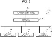
- FIG. 9 is a diagram of a configuration of a reprogramming system 100 according to a second embodiment of the present invention.
- the reprogramming system 100 is a system in which vehicle control devices mounted in a vehicle respectively update control programs which are executed by these vehicle control devices.
- the reprogramming system 100 includes the plurality of vehicle control devices 1, a repeater 6, and a reprogramming device 2.
- each vehicle control device 1 has a structure similar to that of the first embodiment, the vehicle control devices 1 are distinguished from each other by providing alphabets to the respective devices. However, the control program executed by at least one of the vehicle control devices 1 is different from the control program executed by the other vehicle control device 1.
- the repeater 6 is arranged between the reprogramming device 2 and the vehicle control devices 1 and relays communication between the reprogramming device 2 and each vehicle control device 1 via an in-vehicle network 5.
- the repeater 6 can be arranged between a terminal to connect the reprogramming device 2 to the vehicle and the in-vehicle network 5.
- the position of the repeater 6 is not limited to the above.
- the in-vehicle network 5 is a bus network. While the repeater 6 is communicating with one of the vehicle control devices 1, the repeater 6 cannot communicate with the other vehicle control devices 1.
- the reprogramming device 2 transmits the reprogramming instruction to each vehicle control device 1 and the updated version of the control program to be transmitted to each vehicle control device 1 to the repeater 6 once.
- the repeater 6 transmits the reprogramming instruction and the updated version of the control program to either one of the vehicle control devices 1 (for example, vehicle control device 1a).
- the vehicle control device 1 which has received them starts the reprogramming sequence described in the first embodiment.
- the rewriting program 122 is writing the updated version of the control program to the storage region, a communication slot of the in-vehicle network 5 is empty.
- the repeater 6 transmits the reprogramming instruction and the updated version of the control program to the other vehicle control device 1 by using the above time zone. According to this, even in the bus-type in-vehicle network 5, the reprogramming instruction and the control program can be transmitted to the vehicle control devices 1 in parallel, and this makes the time required for the reprogramming work be shorter.
- the present invention is not limited to the embodiments described above and includes various modifications.
- the embodiments have been described in detail for easy understanding of the present invention.
- the embodiments are not limited to those including all the components described above.
- the flash ROM is exemplified as the storage device 12.
- the present invention can be applied. This is because, since the storage region to which the control program is written is collectively updated in normal cases, old data stored in the storage region is erased once before the update. That is, even when the storage device, of which the storage region does not need to be initialized before new data is overwritten, such as a flash ROM is used, the present invention has a certain effect.
- the storage device 12 is divided into the first area 124 and the second area 125.
- the same configuration can be realized by using two storage devices.
- the configuration similar to those of the first and second embodiments can be realized by providing two or more storage regions (or storage devices). In this case, for example, the control program is stored in the storage regions (or storage devices) in order.
- the latest version of the control program is normally written.
- the updated version of the control program indicates the down version of the control program. That is, the updated version of the control program is a control program written by the previous reprogramming sequence.
- the structure, the function, processor, processing method, and the like can be realized with hardware by designing a part of them by using an integrated circuit. Also, the structure, the function, and the like can be realized with software by interpreting and executing programs, which realizes the respective functions, by a processor. Information such as a program, a table, and a file for realizing each function can be stored in a recording device such as a memory, a hard disk, and a solid state drive (SSD) and a record media such as an IC card, an SD card, and a DVD.
- a recording device such as a memory, a hard disk, and a solid state drive (SSD) and a record media such as an IC card, an SD card, and a DVD.
- SSD solid state drive
Abstract
Description
- The present invention relates to a vehicle control device.
- A vehicle control device includes an operation device for executing a control program which implements an operation to control a vehicle (for example, microcomputer) and a storage device such as a flash read only memory (ROM) for storing the control program. The control program is rewritten into an updated version, for example, by connecting a reprogramming device to the vehicle during a maintenance work and transmitting the updated version of the control program from the reprogramming device to the vehicle control device via an in-vehicle network.
- In recent years, a program size of the control program has been increased as processing has become more complicated. Therefore, the processing for rewriting the control program takes a certain period of time in general.
PTL 1 discloses a technique for rewriting control software of an automobile control unit in a short time. - PTL 1:
JP 2006-301960 A - There are cases where a vehicle control device uses a storage device such as a flash ROM. It is necessary to initialize a storage region in which old data is stored before data is updated. The initialization processing takes relatively long time in general. When the control program is stored in the above storage device, it is necessary to perform processing for initializing the storage region, in which the old program is stored, before the control program is updated. Therefore, this causes a long updating work.
- In
PTL 1, the shorter rewriting of control program is enabled by providing a main storage area for storing a current version of the control program and a sub storage area for storing the updated version in a nonvolatile memory. However, inPTL 1, time required to initialize the storage region is not considered. - The present invention has been made to solve the above problems, and a purpose of the present invention is to provide a vehicle control device which can reduce time required to rewrite a control program.
- In the vehicle control device according to the present invention, after an updated version of the control program has been stored in a second storage unit, a first storage unit is initialized in advance before the instruction to update the control program has been executed.
- In accordance with a vehicle control device according to the present invention, processing for initializing a storage unit is separated from processing for rewriting a control program, and a storage region where an old control program is stored is initialized until the next update. Therefore, rewrite processing can be completed in a short time.
-
- [
FIG. 1] FIG. 1 is a diagram of a configuration of avehicle control device 1 according to a first embodiment. - [
FIG. 2] FIG. 2 is a diagram of a structure ofmanagement data 123. - [
FIG. 3] FIG. 3 is a diagram of a traditional reprogramming sequence. - [
FIG. 4] FIG. 4 is a diagram of a sequence to perform reprogramming by thevehicle control device 1 according to the first embodiment. - [
FIG. 5] FIG. 5 is a flowchart to describe a procedure for performing the reprogramming sequence by arewriting program 122. - [
FIG. 6] FIG. 6 is an operation flow of therewriting program 122 when anignition 3 is turned OFF. - [
FIG. 7] FIG. 7 is an operation flow of astartup program 121 when theignition 3 is turned ON. - [
FIG. 8] FIG. 8 is a diagram of a peripheral circuit of thevehicle control device 1. - [
FIG. 9] FIG. 9 is a diagram of a configuration of areprogramming system 100 according to a second embodiment. -
FIG. 1 is a diagram of a configuration of avehicle control device 1 according to a first embodiment of the present invention. Thevehicle control device 1 executes a control program which controls an operation of a vehicle. When anignition 3 included in the vehicle is turned ON, power is supplied to thevehicle control device 1 via apower circuit 4. Thevehicle control device 1 is connected to areprogramming device 2 via an in-vehicle network 5. - The
reprogramming device 2 rewrites the control program executed by thevehicle control device 1 to an updated version. For example, an operator connects thereprogramming device 2 to the vehicle during a maintenance work. The operator transmits an update instruction (reprogramming instruction) of the control program and the updated version to thevehicle control device 1 by operating thereprogramming device 2. - The
vehicle control device 1 includes anoperation unit 11 and astorage device 12. Theoperation unit 11 is an operation device such as a microcomputer which executes the control program stored in thestorage device 12. For convenience of description, there is a case where each of the programs is described as an operating subject. However, theoperation unit 11 actually executes the programs. - The
storage device 12 is a nonvolatile storage device such as a flash ROM and stores astartup program 121, arewriting program 122, andmanagement data 123. Thestorage device 12 further includes afirst area 124 and asecond area 125. - The
startup program 121 is executed by theoperation unit 11 at the beginning when thevehicle control device 1 is started in a normal mode. Therewriting program 122 rewrites the control program stored in thefirst area 124 or thesecond area 125 to the updated version according to an instruction from thereprogramming device 2. Themanagement data 123 is described below. Thefirst area 124 and thesecond area 125 are storage regions where the control program is stored. In a state illustrated inFIG. 1 , it is assumed that thefirst area 124 store a current version of the control program and thesecond area 125 be empty. -
FIG. 2 is a diagram of a structure of themanagement data 123. Themanagement data 123 holds anunused area number 1231, an unusedarea head address 1232, anunused area size 1233, and an unused area erasedstate 1234. - The
unused area number 1231 holds information indicating which of thefirst area 124 or thesecond area 125 stores the current version of the control program. The unusedarea head address 1232 and theunused area size 1233 respectively hold a head address and an area size of one of thefirst area 124 or thesecond area 125 which does not store the current version of the control program. The unused area erasedstate 1234 holds information indicating whether one of thefirst area 124 or thesecond area 125 which does not store the current version of the control program has been completely initialized. A reason for interruption of the initialization is described below. -
FIG. 3 is a diagram of a traditional reprogramming sequence.FIG. 3 is illustrated for comparison with the present invention. A problem in the traditional reprogramming sequence is described below with reference toFIG. 3 . - The operator turns ON the power source (for example, the ignition 3) of the
vehicle control device 1. After that, the operator connects thereprogramming device 2 to the vehicle and starts reprogramming (processing for updating the control program). Thereprogramming device 2 issues a command that instructs thevehicle control device 1 to update control programming. When theoperation unit 11 receives the command, a mode of theoperation unit 11 is changed to a reprogramming mode. - The
reprogramming device 2 instructs thevehicle control device 1 to erase the old data stored in a ROM area where the control program is stored. Theoperation unit 11 erases the data in the ROM area according to the instruction. When the data in the ROM area is completely erased, theoperation unit 11 issues a response indicating that. Thereprogramming device 2 transmits the updated version of the control program to thevehicle control device 1, and theoperation unit 11 writes the updated version to the ROM area in which the data has been erased. When theoperation unit 11 issues the response that indicating that the write has been completed, both thereprogramming device 2 and thevehicle control device 1 check the validity of the written data. When the validity of the written control program is confirmed, theoperation unit 11 ends the reprogramming mode and changes its mode to the normal mode. - In the reprogramming sequence, before the updated version of the control program is written to the ROM, the old data stored in the writing destination region has been previously erased. This is because the ROM stores fixed data and a whole storage region of the ROM is collectively updated in general. Especially, when a device such as a flash ROM is used, the initialization processing takes relatively long time. Regarding the above device, it is necessary not only to simply update the storage region but also to initialize the storage region before the storage region, in which the old data is stored, is updated. Therefore, the initialization processing lowers an efficiency of the reprogramming work.
-
FIG. 4 is a diagram of a sequence to perform the reprogramming by thevehicle control device 1 according to the first embodiment. The reprogramming sequence according to the first embodiment is described below with reference toFIG. 4 . - The operator starts reprogramming as in the traditional reprogramming sequence. The
reprogramming device 2 inquires of thevehicle control device 1 about the unused area of the storage device 12 (area where the current version of the control program is not stored, and in addition, where the initialization of the storage region has been completed). Theoperation unit 11 makes a response about which one of thefirst area 124 or thesecond area 125 is unused with reference to themanagement data 123 together with the unusedarea head address 1232 and theunused area size 1233. - The
reprogramming device 2 instructs thevehicle control device 1 to write the updated version of the control program to the unused area. Therewriting program 122 writes the updated version of the control program (to thesecond area 125 inFIG. 1 ) according to the instruction from thereprogramming device 2. After that, until the mode is changed to the normal mode, the operation is the same as that in the traditional sequence described inFIG. 3 . - In the above sequence, since the
rewriting program 122 writes the updated version of the control program to the unused area (here, initialized second area 125), it is not necessary to initialize that area before the writing. Therefore, the reprogramming sequence can be completed in a short time. - In the next reprogramming sequence, to reduce time to initialize the storage region, it is necessary to initialize the storage region of the writing destination before the next reprogramming sequence is started. Therefore, the
rewriting program 122 initializes the unused area (here, the first area 124), for example, a period from the time when theignition 3 of the vehicle is turned OFF to the time when thevehicle control device 1 is shut down. A method to maintain the power source after theignition 3 has been turned OFF is described below. -
FIG. 5 is a flowchart to describe a procedure for performing the reprogramming sequence by therewriting program 122. Each step inFIG. 5 is described below. - When receiving the reprogramming instruction from the
reprogramming device 2, theoperation unit 11 starts this flowchart and starts the rewriting program 122 (S500). Theoperation unit 11 changes its mode to the reprogramming mode (S501). - The
rewriting program 122 turns ON a power source holding signal. The signal is used to connect a battery of the vehicle to thevehicle control device 1 and to continue to supply power even when theignition 3 of the vehicle is turned OFF. The signal is described below in detail. - According to the procedure described in
FIG. 4 , therewriting program 122 receives the updated version of the control program from thereprogramming device 2 and writes it to the unused area (inFIG. 1 , the second area 125). Then, therewriting program 122 checks the validity of the updated version. - The
rewriting program 122 writes the number, the head address, and the size of the storage region where the control program before the update has been held (inFIG. 1 , the first area 124) to the management data 123 (S506). By the above processing, the reprogramming sequence is completed, and theoperation unit 11 changes its mode to the normal mode (S507). -
FIG. 6 is an operation flow of therewriting program 122 when theignition 3 is turned OFF. Each step inFIG. 6 is described below. - When detecting that the
ignition 3 is turned OFF according to an interruption signal and the like, theoperation unit 11 starts this flowchart and starts therewriting program 122. - The
rewriting program 122 checks the unused area erasedstate 1234 of themanagement data 123. When it is indicated that the unused area erasedstate 1234 has been erased, the procedure proceeds to step S606. When it is indicated that the unused area erasedstate 1234 has not been erased, the procedure proceeds to step S602. - In step S603 or S604 to be described below, the
rewriting program 122 initializes the storage region of thestorage device 12. That is, when theignition 3 is turned OFF, therewriting program 122 initializes the storage region. Therefore, when theignition 3 is turned ON in the middle of the initialization, therewriting program 122 interrupts the initialization processing, and theoperation unit 11 executes thestartup program 121. In this way, there is a possibility that the initialization processing is interrupted. Therefore, therewriting program 122 refers to the unused area erasedstate 1234 in this step and checks whether the initialization has been completed before starting the initialization. - The
rewriting program 122 specifies a storage region to be initialized with reference to the unused area number 1231 (5602). Therewriting program 122 initializes the storage region in which the old control program is stored according to the written unused area number 1231 (S603 and 5604). - In a case where the previous initialization processing is interrupted in the middle, the
rewriting program 122 initializes the unused area again from the head address. When it is desired to restart the initialization processing from a point where the previous initialization processing has been interrupted, a method is considered in which an initialization start address and an initialized address are managed in themanagement data 123 and the initialization processing is restarted from the point where the previous processing has been interrupted with reference to the above addresses. - The
rewriting program 122 writes information, which indicates that the unused area has been erased, to the unused area erased state 1234 (S605) . Therewriting program 122 turns OFF the power source holding signal (S606). -
FIG. 7 is an operation flow of thestartup program 121 when theignition 3 is turned ON. Each step inFIG. 7 is described below. - When detecting that the
ignition 3 is turned ON according to the interruption signal and the like, theoperation unit 11 starts this flowchart and starts thestartup program 121. - The
startup program 121 specifies a storage region where the current version of the control program is stored with reference to theunused area number 1231 of the management data 123 (5701). When thefirst area 124 is unused, the control program stored in thesecond area 125 is executed. Also, when thesecond area 125 is unused, the control program stored in thefirst area 124 is executed. -
FIG. 8 is a diagram of a peripheral circuit of thevehicle control device 1. For convenience of description, only theoperation unit 11 of thevehicle control device 1 is illustrated. Other circuit configurations are included in the vehicle which has thevehicle control device 1 mounted therein. - In
FIG. 8 , when theignition 3 is turned ON, a battery Vbat is connected to thevehicle control device 1, and thevehicle control device 1 operates while having the battery Vbat as a power source. A relay circuit is turned ON in a case where at least one of theignition 3 and the power source holding signal output from the vehicle control device 1 (described in step S502) is turned ON and connects the battery Vbat to thevehicle control device 1. That is, when at least one of theignition 3 and the power source holding signal is turned ON, thevehicle control device 1 can receive the power supply and can be operated. - The
rewriting program 122 initializes the storage region by using a period of time when the ignition is turned OFF. Therefore, in step S502, while the power source holding signal is turned ON and the storage region is initialized, the power is continuously supplied. After the initialization processing has been finished, in step S606, the power source holding signal is turned OFF, and the battery Vbat is cut off. - As described above, after storing the updated version of the control program in the
second area 125, thevehicle control device 1 according to the first embodiment initializes thefirst area 124 before the next reprogramming sequence is restarted. According to this, not only the processing for storing the updated version of the control program in thesecond area 125 but also the next reprogramming sequence can be completed in a short time. - Also, after writing the updated version of the control program, the
vehicle control device 1 according to the first embodiment initializes the unused area in a period from a time when theignition 3 is turned OFF to a time when thevehicle control device 1 is shut down. Accordingly, the reprogramming sequence can be completed in a short time by effectively using a spare time of thevehicle control device 1. -
FIG. 9 is a diagram of a configuration of areprogramming system 100 according to a second embodiment of the present invention. Thereprogramming system 100 is a system in which vehicle control devices mounted in a vehicle respectively update control programs which are executed by these vehicle control devices. Thereprogramming system 100 includes the plurality ofvehicle control devices 1, arepeater 6, and areprogramming device 2. - Since each
vehicle control device 1 has a structure similar to that of the first embodiment, thevehicle control devices 1 are distinguished from each other by providing alphabets to the respective devices. However, the control program executed by at least one of thevehicle control devices 1 is different from the control program executed by the othervehicle control device 1. - The
repeater 6 is arranged between thereprogramming device 2 and thevehicle control devices 1 and relays communication between thereprogramming device 2 and eachvehicle control device 1 via an in-vehicle network 5. For example, therepeater 6 can be arranged between a terminal to connect thereprogramming device 2 to the vehicle and the in-vehicle network 5. However, the position of therepeater 6 is not limited to the above. - The in-
vehicle network 5 is a bus network. While therepeater 6 is communicating with one of thevehicle control devices 1, therepeater 6 cannot communicate with the othervehicle control devices 1. - The
reprogramming device 2 transmits the reprogramming instruction to eachvehicle control device 1 and the updated version of the control program to be transmitted to eachvehicle control device 1 to therepeater 6 once. - The
repeater 6 transmits the reprogramming instruction and the updated version of the control program to either one of the vehicle control devices 1 (for example,vehicle control device 1a). Thevehicle control device 1 which has received them starts the reprogramming sequence described in the first embodiment. While therewriting program 122 is writing the updated version of the control program to the storage region, a communication slot of the in-vehicle network 5 is empty. Then, therepeater 6 transmits the reprogramming instruction and the updated version of the control program to the othervehicle control device 1 by using the above time zone. According to this, even in the bus-type in-vehicle network 5, the reprogramming instruction and the control program can be transmitted to thevehicle control devices 1 in parallel, and this makes the time required for the reprogramming work be shorter. - The present invention is not limited to the embodiments described above and includes various modifications. The embodiments have been described in detail for easy understanding of the present invention. The embodiments are not limited to those including all the components described above.
- In the first and second embodiments, the flash ROM is exemplified as the
storage device 12. However, even when the other nonvolatile storage device is used, the present invention can be applied. This is because, since the storage region to which the control program is written is collectively updated in normal cases, old data stored in the storage region is erased once before the update. That is, even when the storage device, of which the storage region does not need to be initialized before new data is overwritten, such as a flash ROM is used, the present invention has a certain effect. - In the first and second embodiments, an example of the configuration has been described in which the
storage device 12 is divided into thefirst area 124 and thesecond area 125. However, the same configuration can be realized by using two storage devices. The configuration similar to those of the first and second embodiments can be realized by providing two or more storage regions (or storage devices). In this case, for example, the control program is stored in the storage regions (or storage devices) in order. - In the reprogramming sequence, the latest version of the control program is normally written. However, there is a possibility to reprogram a down version of the control program for some reasons. In this case, the updated version of the control program indicates the down version of the control program. That is, the updated version of the control program is a control program written by the previous reprogramming sequence.
- The structure, the function, processor, processing method, and the like can be realized with hardware by designing a part of them by using an integrated circuit. Also, the structure, the function, and the like can be realized with software by interpreting and executing programs, which realizes the respective functions, by a processor. Information such as a program, a table, and a file for realizing each function can be stored in a recording device such as a memory, a hard disk, and a solid state drive (SSD) and a record media such as an IC card, an SD card, and a DVD.
-
- 1
- vehicle control device
- 11
- operation unit
- 12
- storage device
- 121
- startup program
- 122
- rewriting program
- 123
- management data
- 124
- first area
- 125
- second area
- 2
- reprogramming device
- 3
- ignition
- 4
- power circuit
- 5
- in-vehicle network
- 6
- repeater
- 100
- reprogramming system
Claims (10)
- A vehicle control device comprising:a storage device configured to store a control program for implementing an operation to control a vehicle;an operation unit configured to execute the control program; anda rewriting unit configured to rewrite the control program stored in the storage device, whereinthe storage device includes a first storage unit and a second storage unit for storing the control program,after an updated version of the control program stored in the first storage unit has been stored in the second storage unit, the rewriting unit initializes the first storage unit before starting to execute a command to instruct to update the control program stored in the second storage unit, andthe operation unit executes the updated version of the control program which has been stored in the storage device by the rewriting unit.
- The vehicle control device according to claim 1, wherein
after the updated version of the control program stored in the first storage unit has been stored in the second storage unit, the rewriting unit initializes the first storage unit when an ignition switch of the vehicle is turned OFF. - The vehicle control device according to claim 2, wherein
in a process in which the updated version of the control program is written to the second storage unit, the rewriting unit connects a battery included in the vehicle to the vehicle control device regardless of the ON/OFF state of the ignition switch before initializing the first storage unit. - The vehicle control device according to claim 2, wherein
after the rewriting unit has stored the updated version of the control program in the storage device, the operation unit executes the updated version of the control program when the ignition switch is turned ON. - The vehicle control device according to claim 4, wherein
when the ignition switch is turned ON while the first storage unit is initialized, the rewriting unit interrupts the processing for initializing the first storage unit, and the operation unit executes the updated version of the control program. - The vehicle control device according to claim 5, wherein
the storage device stores management data for holding information indicating whether the rewriting unit has completed the initialization of the first storage unit,
the rewriting unit writes the information indicating that the initialization of the first storage unit has been completed to the management data when the initialization of the first storage unit has been completed, and
when the ignition switch is turned OFF, the rewriting unit does not initialize the first storage unit in a case where the information indicating that the initialization of the first storage unit has been completed has been written to the management data and initializes the first storage unit in a case where the information indicating that the initialization of the first storage unit has not been completed has been written to the management data. - The vehicle control device according to claim 1, wherein
the storage device stores management data for holding information indicating which one of the first storage unit and the second storage unit stores the updated version of the control program, and
the rewriting unit stores the new updated version of the control program in one of the first storage unit or the second storage unit which does not store the updated version of the control program and initializes the other storage unit. - The vehicle control device according to claim 1, wherein
the storage device is a device having a storage region which needs to be initialized before stored data is updated. - A reprogramming system comprising:the plurality of vehicle control devices according to claim 1;a reprogramming device configured to instruct the plurality of vehicle control devices to update the control program and transmit the updated version of the control program to the plurality of vehicle control devices; anda repeater configured to relay communication between the reprogramming device and the plurality of vehicle control devices.
- The reprogramming system according to claim 9, wherein
a bus network connects between the repeater and the plurality of vehicle control devices,
at least one of the vehicle control devices executes the control program different from that of the other vehicle control device, and
when one of the vehicle control devices writes the updated version of the control program to the storage device, the repeater transmits the updated version of the control program to the other vehicle control device.
Applications Claiming Priority (2)
| Application Number | Priority Date | Filing Date | Title |
|---|---|---|---|
| JP2014196089 | 2014-09-26 | ||
| PCT/JP2015/072985 WO2016047312A1 (en) | 2014-09-26 | 2015-08-17 | Vehicle control device, reprogramming system |
Publications (3)
| Publication Number | Publication Date |
|---|---|
| EP3200077A1 true EP3200077A1 (en) | 2017-08-02 |
| EP3200077A4 EP3200077A4 (en) | 2018-10-10 |
| EP3200077B1 EP3200077B1 (en) | 2022-03-09 |
Family
ID=55580843
Family Applications (1)
| Application Number | Title | Priority Date | Filing Date |
|---|---|---|---|
| EP15844264.0A Active EP3200077B1 (en) | 2014-09-26 | 2015-08-17 | Vehicle control device, reprogramming system |
Country Status (5)
| Country | Link |
|---|---|
| US (1) | US10241807B2 (en) |
| EP (1) | EP3200077B1 (en) |
| JP (1) | JP6227794B2 (en) |
| CN (1) | CN106462479B (en) |
| WO (1) | WO2016047312A1 (en) |
Cited By (1)
| Publication number | Priority date | Publication date | Assignee | Title |
|---|---|---|---|---|
| EP3575954A4 (en) * | 2017-01-25 | 2020-10-21 | Hitachi Automotive Systems, Ltd. | Vehicle control device and program updating system |
Families Citing this family (10)
| Publication number | Priority date | Publication date | Assignee | Title |
|---|---|---|---|---|
| EP3249531B1 (en) * | 2015-01-23 | 2022-01-05 | Kobelco Construction Machinery Co., Ltd. | Control means, in-vehicle program rewriting device equipped with same, and in-vehicle program rewriting method |
| JP6571602B2 (en) * | 2016-07-26 | 2019-09-04 | 日立オートモティブシステムズ株式会社 | Vehicle control device, in-vehicle network system |
| US10416985B2 (en) * | 2017-02-16 | 2019-09-17 | Ford Global Technologies, Llc | Method and apparatus for multi cycle vehicle software update compliance handling |
| WO2018230084A1 (en) * | 2017-06-13 | 2018-12-20 | 住友電気工業株式会社 | Updating control device, control method, and computer program |
| JP7006335B2 (en) * | 2018-02-06 | 2022-01-24 | トヨタ自動車株式会社 | In-vehicle communication system, in-vehicle communication method, and program |
| US11449329B2 (en) * | 2018-02-16 | 2022-09-20 | Hitachi Astemo, Ltd. | Vehicle control device and program update system |
| JP7193940B2 (en) * | 2018-07-20 | 2022-12-21 | 株式会社デンソーテン | Controller and program update method |
| US11340884B2 (en) * | 2019-06-20 | 2022-05-24 | Toyota Motor Engineering & Manufacturing North America, Inc. | Systems and methods for distributing updates |
| US11762575B2 (en) * | 2019-07-31 | 2023-09-19 | Hewlett-Packard Development Company, L.P. | Updates to flash memory based on determinations of bits to erase |
| JP7320547B2 (en) * | 2021-03-19 | 2023-08-03 | 本田技研工業株式会社 | Program update control device, program update control method, and program |
Family Cites Families (18)
| Publication number | Priority date | Publication date | Assignee | Title |
|---|---|---|---|---|
| JP2000259422A (en) * | 1999-03-12 | 2000-09-22 | Denso Corp | Electronic controller |
| DE10012272B4 (en) * | 2000-03-14 | 2004-04-08 | Daimlerchrysler Ag | Method for storing data in computer-aided means of transport |
| JP2005071155A (en) * | 2003-08-26 | 2005-03-17 | Alps Electric Co Ltd | Communication equipment terminal with updatable firmware |
| JP4548601B2 (en) | 2005-04-20 | 2010-09-22 | 株式会社デンソー | Automotive control unit |
| JP2007011734A (en) * | 2005-06-30 | 2007-01-18 | Denso Corp | On-vehicle control unit |
| EP1892622B1 (en) * | 2006-08-08 | 2013-12-04 | Snap-on Equipment Srl a unico socio | Method and apparatus for updating of software and/or collecting of operational data in a machine unit |
| US8332838B2 (en) * | 2007-11-14 | 2012-12-11 | Continental Automotive Systems, Inc. | Systems and methods for updating device software |
| DE102008041360A1 (en) * | 2008-08-20 | 2010-02-25 | Robert Bosch Gmbh | A vehicle control unit and a data update method for a vehicle control unit |
| JP2010140325A (en) * | 2008-12-12 | 2010-06-24 | Panasonic Corp | Microcomputer control device |
| JP2010198155A (en) * | 2009-02-24 | 2010-09-09 | Fujitsu Ten Ltd | Device and method for updating program, and information processing apparatus |
| JP5267598B2 (en) * | 2011-02-25 | 2013-08-21 | トヨタ自動車株式会社 | Data rewrite support system and data rewrite support method for vehicle control device |
| CN102135922B (en) * | 2011-03-18 | 2015-08-19 | 北京经纬恒润科技有限公司 | The method for refreshing of application program and system |
| CN103095745B (en) * | 2011-10-28 | 2016-04-13 | 上海移远通信技术有限公司 | Car-mounted terminal, electronic module, electronic module update device, system and method |
| US9536361B2 (en) * | 2012-03-14 | 2017-01-03 | Autoconnect Holdings Llc | Universal vehicle notification system |
| US8813061B2 (en) * | 2012-10-17 | 2014-08-19 | Movimento Group | Module updating device |
| US9248789B2 (en) * | 2014-01-08 | 2016-02-02 | Verizon Patent And Licensing Inc. | Method and apparatus for detecting key-on and key-off states using time-to-frequency transforms |
| US10140109B2 (en) * | 2014-02-25 | 2018-11-27 | Ford Global Technologies, Llc | Silent in-vehicle software updates |
| US20160196132A1 (en) * | 2014-07-07 | 2016-07-07 | Symphony Teleca Corporation | Remote Embedded Device Update Platform Apparatuses, Methods and Systems |
-
2015
- 2015-08-17 CN CN201580033294.0A patent/CN106462479B/en active Active
- 2015-08-17 EP EP15844264.0A patent/EP3200077B1/en active Active
- 2015-08-17 WO PCT/JP2015/072985 patent/WO2016047312A1/en active Application Filing
- 2015-08-17 US US15/502,552 patent/US10241807B2/en active Active
- 2015-08-17 JP JP2016550031A patent/JP6227794B2/en active Active
Cited By (1)
| Publication number | Priority date | Publication date | Assignee | Title |
|---|---|---|---|---|
| EP3575954A4 (en) * | 2017-01-25 | 2020-10-21 | Hitachi Automotive Systems, Ltd. | Vehicle control device and program updating system |
Also Published As
| Publication number | Publication date |
|---|---|
| EP3200077A4 (en) | 2018-10-10 |
| EP3200077B1 (en) | 2022-03-09 |
| WO2016047312A1 (en) | 2016-03-31 |
| JP6227794B2 (en) | 2017-11-08 |
| CN106462479B (en) | 2019-05-10 |
| US10241807B2 (en) | 2019-03-26 |
| US20170228236A1 (en) | 2017-08-10 |
| JPWO2016047312A1 (en) | 2017-04-27 |
| CN106462479A (en) | 2017-02-22 |
Similar Documents
| Publication | Publication Date | Title |
|---|---|---|
| EP3200077B1 (en) | Vehicle control device, reprogramming system | |
| US20100325623A1 (en) | Robot system, robot control device, and software update method of robot system | |
| US20100122017A1 (en) | Memory controller, non-volatile memory system, and host device | |
| US11392368B2 (en) | Electronic control system for updating circuit | |
| CN104123153A (en) | Apparatus and method for firmware upgrade using USB | |
| US8036786B2 (en) | On-vehicle control apparatus | |
| US11449329B2 (en) | Vehicle control device and program update system | |
| CN111813432A (en) | FPGA configuration upgrading method and FPGA platform | |
| CN101667133B (en) | Method for updating firmware and chip updating firmware by using same | |
| CN112346770A (en) | Embedded program online updating method | |
| JP6001962B2 (en) | Inverter device | |
| JP6575157B2 (en) | Firmware download method and firmware embedded device | |
| CN109697077B (en) | Method, device and equipment for starting hard disk firmware | |
| CN113613954A (en) | Electronic control device and method for setting control data | |
| JP2007316800A (en) | Onboard program rewriting controller | |
| CN112269585B (en) | Joint driver firmware online updating method and device and joint driver | |
| JPH1063497A (en) | Program updating method | |
| US20220204008A1 (en) | Arithmetic processing device, vehicle control device, and update method | |
| JP2008257415A (en) | Controller having program write function | |
| US20220398089A1 (en) | Vehicle control device and program management method | |
| US20220405083A1 (en) | Ota master, system, method, non-transitory storage medium, and vehicle | |
| JP2008305263A (en) | Nonvolatile semiconductor storage device and memory management method | |
| JP5981477B2 (en) | Flash memory control device, flash memory built-in device, flash memory control method, and program therefor | |
| JP2017228033A (en) | On-vehicle storage device, vehicle information storage method and program | |
| JP2023174004A (en) | Vehicle control apparatus and program update method |
Legal Events
| Date | Code | Title | Description |
|---|---|---|---|
| STAA | Information on the status of an ep patent application or granted ep patent |
Free format text: STATUS: THE INTERNATIONAL PUBLICATION HAS BEEN MADE |
|
| PUAI | Public reference made under article 153(3) epc to a published international application that has entered the european phase |
Free format text: ORIGINAL CODE: 0009012 |
|
| STAA | Information on the status of an ep patent application or granted ep patent |
Free format text: STATUS: REQUEST FOR EXAMINATION WAS MADE |
|
| 17P | Request for examination filed |
Effective date: 20170426 |
|
| AK | Designated contracting states |
Kind code of ref document: A1 Designated state(s): AL AT BE BG CH CY CZ DE DK EE ES FI FR GB GR HR HU IE IS IT LI LT LU LV MC MK MT NL NO PL PT RO RS SE SI SK SM TR |
|
| AX | Request for extension of the european patent |
Extension state: BA ME |
|
| DAV | Request for validation of the european patent (deleted) | ||
| DAX | Request for extension of the european patent (deleted) | ||
| RIC1 | Information provided on ipc code assigned before grant |
Ipc: G06F 11/00 20060101ALI20180417BHEP Ipc: G06F 8/654 20180101AFI20180417BHEP |
|
| A4 | Supplementary search report drawn up and despatched |
Effective date: 20180910 |
|
| RIC1 | Information provided on ipc code assigned before grant |
Ipc: G06F 8/654 20180101AFI20180904BHEP Ipc: G06F 11/00 20060101ALI20180904BHEP |
|
| STAA | Information on the status of an ep patent application or granted ep patent |
Free format text: STATUS: EXAMINATION IS IN PROGRESS |
|
| 17Q | First examination report despatched |
Effective date: 20190816 |
|
| STAA | Information on the status of an ep patent application or granted ep patent |
Free format text: STATUS: EXAMINATION IS IN PROGRESS |
|
| RAP3 | Party data changed (applicant data changed or rights of an application transferred) |
Owner name: HITACHI ASTEMO, LTD. |
|
| REG | Reference to a national code |
Ref country code: DE Ref legal event code: R079 Ref document number: 602015077463 Country of ref document: DE Free format text: PREVIOUS MAIN CLASS: G06F0011000000 Ipc: G06F0009445000 |
|
| GRAP | Despatch of communication of intention to grant a patent |
Free format text: ORIGINAL CODE: EPIDOSNIGR1 |
|
| STAA | Information on the status of an ep patent application or granted ep patent |
Free format text: STATUS: GRANT OF PATENT IS INTENDED |
|
| RIC1 | Information provided on ipc code assigned before grant |
Ipc: G06F 11/00 20060101ALI20211012BHEP Ipc: G06F 8/654 20180101ALI20211012BHEP Ipc: G06F 9/445 20180101AFI20211012BHEP |
|
| INTG | Intention to grant announced |
Effective date: 20211105 |
|
| GRAS | Grant fee paid |
Free format text: ORIGINAL CODE: EPIDOSNIGR3 |
|
| GRAA | (expected) grant |
Free format text: ORIGINAL CODE: 0009210 |
|
| STAA | Information on the status of an ep patent application or granted ep patent |
Free format text: STATUS: THE PATENT HAS BEEN GRANTED |
|
| AK | Designated contracting states |
Kind code of ref document: B1 Designated state(s): AL AT BE BG CH CY CZ DE DK EE ES FI FR GB GR HR HU IE IS IT LI LT LU LV MC MK MT NL NO PL PT RO RS SE SI SK SM TR |
|
| REG | Reference to a national code |
Ref country code: GB Ref legal event code: FG4D |
|
| REG | Reference to a national code |
Ref country code: CH Ref legal event code: EP Ref country code: AT Ref legal event code: REF Ref document number: 1474728 Country of ref document: AT Kind code of ref document: T Effective date: 20220315 |
|
| REG | Reference to a national code |
Ref country code: IE Ref legal event code: FG4D |
|
| REG | Reference to a national code |
Ref country code: DE Ref legal event code: R096 Ref document number: 602015077463 Country of ref document: DE |
|
| REG | Reference to a national code |
Ref country code: LT Ref legal event code: MG9D |
|
| REG | Reference to a national code |
Ref country code: NL Ref legal event code: MP Effective date: 20220309 |
|
| PG25 | Lapsed in a contracting state [announced via postgrant information from national office to epo] |
Ref country code: SE Free format text: LAPSE BECAUSE OF FAILURE TO SUBMIT A TRANSLATION OF THE DESCRIPTION OR TO PAY THE FEE WITHIN THE PRESCRIBED TIME-LIMIT Effective date: 20220309 Ref country code: RS Free format text: LAPSE BECAUSE OF FAILURE TO SUBMIT A TRANSLATION OF THE DESCRIPTION OR TO PAY THE FEE WITHIN THE PRESCRIBED TIME-LIMIT Effective date: 20220309 Ref country code: NO Free format text: LAPSE BECAUSE OF FAILURE TO SUBMIT A TRANSLATION OF THE DESCRIPTION OR TO PAY THE FEE WITHIN THE PRESCRIBED TIME-LIMIT Effective date: 20220609 Ref country code: LT Free format text: LAPSE BECAUSE OF FAILURE TO SUBMIT A TRANSLATION OF THE DESCRIPTION OR TO PAY THE FEE WITHIN THE PRESCRIBED TIME-LIMIT Effective date: 20220309 Ref country code: HR Free format text: LAPSE BECAUSE OF FAILURE TO SUBMIT A TRANSLATION OF THE DESCRIPTION OR TO PAY THE FEE WITHIN THE PRESCRIBED TIME-LIMIT Effective date: 20220309 Ref country code: BG Free format text: LAPSE BECAUSE OF FAILURE TO SUBMIT A TRANSLATION OF THE DESCRIPTION OR TO PAY THE FEE WITHIN THE PRESCRIBED TIME-LIMIT Effective date: 20220609 |
|
| REG | Reference to a national code |
Ref country code: AT Ref legal event code: MK05 Ref document number: 1474728 Country of ref document: AT Kind code of ref document: T Effective date: 20220309 |
|
| PG25 | Lapsed in a contracting state [announced via postgrant information from national office to epo] |
Ref country code: LV Free format text: LAPSE BECAUSE OF FAILURE TO SUBMIT A TRANSLATION OF THE DESCRIPTION OR TO PAY THE FEE WITHIN THE PRESCRIBED TIME-LIMIT Effective date: 20220309 Ref country code: GR Free format text: LAPSE BECAUSE OF FAILURE TO SUBMIT A TRANSLATION OF THE DESCRIPTION OR TO PAY THE FEE WITHIN THE PRESCRIBED TIME-LIMIT Effective date: 20220610 Ref country code: FI Free format text: LAPSE BECAUSE OF FAILURE TO SUBMIT A TRANSLATION OF THE DESCRIPTION OR TO PAY THE FEE WITHIN THE PRESCRIBED TIME-LIMIT Effective date: 20220309 |
|
| PG25 | Lapsed in a contracting state [announced via postgrant information from national office to epo] |
Ref country code: NL Free format text: LAPSE BECAUSE OF FAILURE TO SUBMIT A TRANSLATION OF THE DESCRIPTION OR TO PAY THE FEE WITHIN THE PRESCRIBED TIME-LIMIT Effective date: 20220309 |
|
| PG25 | Lapsed in a contracting state [announced via postgrant information from national office to epo] |
Ref country code: SM Free format text: LAPSE BECAUSE OF FAILURE TO SUBMIT A TRANSLATION OF THE DESCRIPTION OR TO PAY THE FEE WITHIN THE PRESCRIBED TIME-LIMIT Effective date: 20220309 Ref country code: SK Free format text: LAPSE BECAUSE OF FAILURE TO SUBMIT A TRANSLATION OF THE DESCRIPTION OR TO PAY THE FEE WITHIN THE PRESCRIBED TIME-LIMIT Effective date: 20220309 Ref country code: RO Free format text: LAPSE BECAUSE OF FAILURE TO SUBMIT A TRANSLATION OF THE DESCRIPTION OR TO PAY THE FEE WITHIN THE PRESCRIBED TIME-LIMIT Effective date: 20220309 Ref country code: PT Free format text: LAPSE BECAUSE OF FAILURE TO SUBMIT A TRANSLATION OF THE DESCRIPTION OR TO PAY THE FEE WITHIN THE PRESCRIBED TIME-LIMIT Effective date: 20220711 Ref country code: ES Free format text: LAPSE BECAUSE OF FAILURE TO SUBMIT A TRANSLATION OF THE DESCRIPTION OR TO PAY THE FEE WITHIN THE PRESCRIBED TIME-LIMIT Effective date: 20220309 Ref country code: EE Free format text: LAPSE BECAUSE OF FAILURE TO SUBMIT A TRANSLATION OF THE DESCRIPTION OR TO PAY THE FEE WITHIN THE PRESCRIBED TIME-LIMIT Effective date: 20220309 Ref country code: CZ Free format text: LAPSE BECAUSE OF FAILURE TO SUBMIT A TRANSLATION OF THE DESCRIPTION OR TO PAY THE FEE WITHIN THE PRESCRIBED TIME-LIMIT Effective date: 20220309 Ref country code: AT Free format text: LAPSE BECAUSE OF FAILURE TO SUBMIT A TRANSLATION OF THE DESCRIPTION OR TO PAY THE FEE WITHIN THE PRESCRIBED TIME-LIMIT Effective date: 20220309 |
|
| PG25 | Lapsed in a contracting state [announced via postgrant information from national office to epo] |
Ref country code: PL Free format text: LAPSE BECAUSE OF FAILURE TO SUBMIT A TRANSLATION OF THE DESCRIPTION OR TO PAY THE FEE WITHIN THE PRESCRIBED TIME-LIMIT Effective date: 20220309 Ref country code: IS Free format text: LAPSE BECAUSE OF FAILURE TO SUBMIT A TRANSLATION OF THE DESCRIPTION OR TO PAY THE FEE WITHIN THE PRESCRIBED TIME-LIMIT Effective date: 20220709 Ref country code: AL Free format text: LAPSE BECAUSE OF FAILURE TO SUBMIT A TRANSLATION OF THE DESCRIPTION OR TO PAY THE FEE WITHIN THE PRESCRIBED TIME-LIMIT Effective date: 20220309 |
|
| REG | Reference to a national code |
Ref country code: DE Ref legal event code: R097 Ref document number: 602015077463 Country of ref document: DE |
|
| PLBE | No opposition filed within time limit |
Free format text: ORIGINAL CODE: 0009261 |
|
| STAA | Information on the status of an ep patent application or granted ep patent |
Free format text: STATUS: NO OPPOSITION FILED WITHIN TIME LIMIT |
|
| PG25 | Lapsed in a contracting state [announced via postgrant information from national office to epo] |
Ref country code: DK Free format text: LAPSE BECAUSE OF FAILURE TO SUBMIT A TRANSLATION OF THE DESCRIPTION OR TO PAY THE FEE WITHIN THE PRESCRIBED TIME-LIMIT Effective date: 20220309 |
|
| 26N | No opposition filed |
Effective date: 20221212 |
|
| PG25 | Lapsed in a contracting state [announced via postgrant information from national office to epo] |
Ref country code: SI Free format text: LAPSE BECAUSE OF FAILURE TO SUBMIT A TRANSLATION OF THE DESCRIPTION OR TO PAY THE FEE WITHIN THE PRESCRIBED TIME-LIMIT Effective date: 20220309 |
|
| PG25 | Lapsed in a contracting state [announced via postgrant information from national office to epo] |
Ref country code: MC Free format text: LAPSE BECAUSE OF FAILURE TO SUBMIT A TRANSLATION OF THE DESCRIPTION OR TO PAY THE FEE WITHIN THE PRESCRIBED TIME-LIMIT Effective date: 20220309 |
|
| REG | Reference to a national code |
Ref country code: CH Ref legal event code: PL |
|
| GBPC | Gb: european patent ceased through non-payment of renewal fee |
Effective date: 20220817 |
|
| PG25 | Lapsed in a contracting state [announced via postgrant information from national office to epo] |
Ref country code: LU Free format text: LAPSE BECAUSE OF NON-PAYMENT OF DUE FEES Effective date: 20220817 Ref country code: LI Free format text: LAPSE BECAUSE OF NON-PAYMENT OF DUE FEES Effective date: 20220831 Ref country code: CH Free format text: LAPSE BECAUSE OF NON-PAYMENT OF DUE FEES Effective date: 20220831 |
|
| REG | Reference to a national code |
Ref country code: BE Ref legal event code: MM Effective date: 20220831 |
|
| PG25 | Lapsed in a contracting state [announced via postgrant information from national office to epo] |
Ref country code: IT Free format text: LAPSE BECAUSE OF FAILURE TO SUBMIT A TRANSLATION OF THE DESCRIPTION OR TO PAY THE FEE WITHIN THE PRESCRIBED TIME-LIMIT Effective date: 20220309 Ref country code: IE Free format text: LAPSE BECAUSE OF NON-PAYMENT OF DUE FEES Effective date: 20220817 Ref country code: FR Free format text: LAPSE BECAUSE OF NON-PAYMENT OF DUE FEES Effective date: 20220831 |
|
| PG25 | Lapsed in a contracting state [announced via postgrant information from national office to epo] |
Ref country code: BE Free format text: LAPSE BECAUSE OF NON-PAYMENT OF DUE FEES Effective date: 20220831 |
|
| PG25 | Lapsed in a contracting state [announced via postgrant information from national office to epo] |
Ref country code: GB Free format text: LAPSE BECAUSE OF NON-PAYMENT OF DUE FEES Effective date: 20220817 |
|
| PGFP | Annual fee paid to national office [announced via postgrant information from national office to epo] |
Ref country code: DE Payment date: 20230627 Year of fee payment: 9 |
|
| PG25 | Lapsed in a contracting state [announced via postgrant information from national office to epo] |
Ref country code: HU Free format text: LAPSE BECAUSE OF FAILURE TO SUBMIT A TRANSLATION OF THE DESCRIPTION OR TO PAY THE FEE WITHIN THE PRESCRIBED TIME-LIMIT; INVALID AB INITIO Effective date: 20150817 |