EP3199784A1 - Brennstoffdurchflusssteuerung - Google Patents
Brennstoffdurchflusssteuerung Download PDFInfo
- Publication number
- EP3199784A1 EP3199784A1 EP17150831.0A EP17150831A EP3199784A1 EP 3199784 A1 EP3199784 A1 EP 3199784A1 EP 17150831 A EP17150831 A EP 17150831A EP 3199784 A1 EP3199784 A1 EP 3199784A1
- Authority
- EP
- European Patent Office
- Prior art keywords
- fuel flow
- demand
- flow demand
- actual
- enhanced
- Prior art date
- Legal status (The legal status is an assumption and is not a legal conclusion. Google has not performed a legal analysis and makes no representation as to the accuracy of the status listed.)
- Granted
Links
Images


Classifications
-
- F—MECHANICAL ENGINEERING; LIGHTING; HEATING; WEAPONS; BLASTING
- F02—COMBUSTION ENGINES; HOT-GAS OR COMBUSTION-PRODUCT ENGINE PLANTS
- F02C—GAS-TURBINE PLANTS; AIR INTAKES FOR JET-PROPULSION PLANTS; CONTROLLING FUEL SUPPLY IN AIR-BREATHING JET-PROPULSION PLANTS
- F02C9/00—Controlling gas-turbine plants; Controlling fuel supply in air- breathing jet-propulsion plants
- F02C9/26—Control of fuel supply
- F02C9/28—Regulating systems responsive to plant or ambient parameters, e.g. temperature, pressure, rotor speed
-
- F—MECHANICAL ENGINEERING; LIGHTING; HEATING; WEAPONS; BLASTING
- F02—COMBUSTION ENGINES; HOT-GAS OR COMBUSTION-PRODUCT ENGINE PLANTS
- F02C—GAS-TURBINE PLANTS; AIR INTAKES FOR JET-PROPULSION PLANTS; CONTROLLING FUEL SUPPLY IN AIR-BREATHING JET-PROPULSION PLANTS
- F02C9/00—Controlling gas-turbine plants; Controlling fuel supply in air- breathing jet-propulsion plants
- F02C9/26—Control of fuel supply
- F02C9/46—Emergency fuel control
-
- F—MECHANICAL ENGINEERING; LIGHTING; HEATING; WEAPONS; BLASTING
- F05—INDEXING SCHEMES RELATING TO ENGINES OR PUMPS IN VARIOUS SUBCLASSES OF CLASSES F01-F04
- F05B—INDEXING SCHEME RELATING TO WIND, SPRING, WEIGHT, INERTIA OR LIKE MOTORS, TO MACHINES OR ENGINES FOR LIQUIDS COVERED BY SUBCLASSES F03B, F03D AND F03G
- F05B2270/00—Control
- F05B2270/30—Control parameters, e.g. input parameters
- F05B2270/301—Pressure
- F05B2270/3013—Outlet
-
- F—MECHANICAL ENGINEERING; LIGHTING; HEATING; WEAPONS; BLASTING
- F05—INDEXING SCHEMES RELATING TO ENGINES OR PUMPS IN VARIOUS SUBCLASSES OF CLASSES F01-F04
- F05D—INDEXING SCHEME FOR ASPECTS RELATING TO NON-POSITIVE-DISPLACEMENT MACHINES OR ENGINES, GAS-TURBINES OR JET-PROPULSION PLANTS
- F05D2270/00—Control
- F05D2270/01—Purpose of the control system
- F05D2270/10—Purpose of the control system to cope with, or avoid, compressor flow instabilities
- F05D2270/101—Compressor surge or stall
-
- F—MECHANICAL ENGINEERING; LIGHTING; HEATING; WEAPONS; BLASTING
- F05—INDEXING SCHEMES RELATING TO ENGINES OR PUMPS IN VARIOUS SUBCLASSES OF CLASSES F01-F04
- F05D—INDEXING SCHEME FOR ASPECTS RELATING TO NON-POSITIVE-DISPLACEMENT MACHINES OR ENGINES, GAS-TURBINES OR JET-PROPULSION PLANTS
- F05D2270/00—Control
- F05D2270/30—Control parameters, e.g. input parameters
- F05D2270/301—Pressure
Definitions
- the present disclosure concerns a method of controlling fuel flow in a gas turbine engine. It also concerns a fuel flow control system and a fuel flow system for a gas turbine engine, which implement the method.
- the amount of fuel flow may be determined by a function which is dependent on an engine shaft speed, a pressure ratio or a combination of these parameters. It may also be modulated by other factors such as altitude, for a gas turbine engine powering an aircraft.
- the fuel flow may be controlled to open loop, without feedback as to whether the instructed fuel flow has resulted in the desired engine speed change, or closed loop, with feedback.
- the line W f_D shows the demanded fuel flow which has a small increase as the actual shaft speed N L_A drops as the control laws try to return the actual shaft speed N L_A to the demanded shaft speed N L_D . Then the demanded fuel flow W f_D drops away tracking the reduction in compressor discharge pressure P 30 .
- the line is stepped due to the time constant of the applicable control law.
- the actual fuel flow W f_A tracks the demanded fuel flow W f_D with a lag.
- the increase in demanded fuel flow W f_D is limited by a maximum rate limiter and so the increase in fuel flow, and consequently the arresting of the actual shaft speed N L_A decrease, is slow. Indeed, as illustrated the demanded and actual fuel flow W f_D , W f_A have only recovered to around 30% of their maximum values by time 1.4 when the speed demand N L_D is significantly reduced whereas before the surge, at the left hand side of Figure 2 , the demanded and actual fuel flows W f_D , W f_A were over 90% of their maximum values.
- a disadvantage of the known method of controlling fuel flow during and following an engine surge is that the fuel flow demand W f_D is heavily depressed by tracking compressor discharge pressure P 30 and is slow to recover to pre-surge levels.
- a method of controlling fuel flow in a gas turbine engine comprising steps to:
- the method recovers fuel flow demand more quickly after a surge than known methods.
- the method may comprise a further step to revert to normal fuel flow control laws once fuel flow demand equals or exceeds the predefined proportion of actual fuel flow.
- the method only applies during surge and recovery.
- Step c) may precede or occur in parallel to step b).
- the method may comprise a step to apply a second enhanced schedule for fuel flow demand while fuel flow demand is less than a second predefined proportion of actual fuel flow demand; wherein the second predefined proportion is smaller than the predefined proportion.
- a second enhanced schedule for fuel flow demand while fuel flow demand is less than a second predefined proportion of actual fuel flow demand; wherein the second predefined proportion is smaller than the predefined proportion.
- the predefined proportion may be in the range 0.5 to 1.5.
- the predefined proportion may be in the range 0.5 to 1.
- the predefined proportion may be in the range 0.75 to 1.
- the second predefined proportion may be in the range 0.5 to 1.5.
- the second predefined proportion may be in the range 0.5 to 1.
- the second predefined proportion may be in the range 0.75 to 1.
- the enhanced schedule may comprise a high rate of increase of fuel flow demand.
- the enhanced schedule may comprise the maximum of a) an enhanced rate of increase defined by the predefined proportion multiplied by the actual fuel flow minus the demanded fuel flow, divided by a time step and b) the normal rate of fuel flow increase.
- the enhanced schedule may comprise the sum of a) the predefined proportion multiplied by the actual fuel flow, and b) one minus the predefined proportion multiplied by the demanded fuel flow.
- each of these embodiments of the enhanced schedule accelerates recovery following an engine surge.
- the enhanced schedule may be limited by a maximum rate of change of fuel flow demand. This may reflect physical constraints of the system, for example valve slew rates, or may reduce the possibility of a recurrence of the surge.
- the second enhanced schedule may comprise a higher rate of increase of fuel flow demand than the enhanced schedule.
- the initial recovery of fuel flow demand from surge is rapid and then the rate slows as the fuel flow demand nears the actual fuel flow to reduce the likelihood of overshoot.
- the actual fuel flow may be measured by a position of a fuel metering valve.
- the present invention also provides a fuel flow control system configured to perform the method as described, and a fuel flow system comprising such a fuel flow control system.
- the present invention also provides a gas turbine engine comprising such a fuel flow control system, and a gas turbine engine comprising such a fuel flow system.
- a gas turbine engine is generally indicated at 10, having a principal and rotational axis 11.
- the engine 10 comprises, in axial flow series, an air intake 12, a propulsive fan 13, an intermediate pressure compressor 14, a high-pressure compressor 15, combustion equipment 16, a high-pressure turbine 17, an intermediate pressure turbine 18, a low-pressure turbine 19 and an exhaust nozzle 20.
- a nacelle 21 generally surrounds the engine 10 and defines both the intake 12 and the exhaust nozzle 20.
- the gas turbine engine 10 works in the conventional manner so that air entering the intake 12 is accelerated by the fan 13 to produce two air flows: a first air flow into the intermediate pressure compressor 14 and a second air flow which passes through a bypass duct 22 to provide propulsive thrust.
- the intermediate pressure compressor 14 compresses the air flow directed into it before delivering that air to the high pressure compressor 15 where further compression takes place.
- the compressed air exhausted from the high-pressure compressor 15 is directed into the combustion equipment 16 where it is mixed with fuel and the mixture combusted.
- the resultant hot combustion products then expand through, and thereby drive the high, intermediate and low-pressure turbines 17, 18, 19 before being exhausted through the nozzle 20 to provide additional propulsive thrust.
- the high 17, intermediate 18 and low 19 pressure turbines drive respectively the high pressure compressor 15, intermediate pressure compressor 14 and fan 13, each by suitable interconnecting shaft.
- gas turbine engines to which the present disclosure may be applied may have alternative configurations.
- such engines may have an alternative number of interconnecting shafts (e.g. two) and/or an alternative number of compressors and/or turbines.
- the engine may comprise a gearbox provided in the drive train from a turbine to a compressor and/or fan.
- a fuel flow system 68 is illustrated schematically in Figure 3 .
- Fuel is supplied to the gas turbine engine 10 from one or more fuel tanks 70, for example located in the aircraft body or wings where the gas turbine engine 10 powers an aircraft.
- the fuel may be pressurised through one or more pumps 72 and delivered to a fuel metering valve 74.
- the fuel metering valve 74 is controlled by a fuel flow control system 76 which implements methods of controlling the fuel flow in the gas turbine engine 10.
- the fuel metering valve 74 delivers the demanded fuel flow to the combustor 16, via one or more sets of fuel injectors.
- a method 30 of controlling fuel flow in a gas turbine engine 10 is described with respect to Figure 4 .
- the method 30 may be implemented in the fuel flow control system 76.
- the method 30 acts in response to a surge condition 32.
- a pre-step to detect the surge condition 32 by any conventional method may be implemented in the method 30.
- surge may be detected from a rapid reduction in compressor discharge pressure P 30 .
- the surge condition 32 need not be detected since the method 30 reacts to the effects of the surge without requiring explicit detection of the surge condition 32.
- step 34 of the method 30 the fuel flow demand W f_D is set to be proportional to the compressor discharge pressure P 30 .
- the relationship between fuel flow demand W f_D and compressor discharge pressure P 30 may be linear, with a constant of proportionality, or may be non-linear.
- the relationship between fuel flow demand W f_D and compressor discharge pressure P 30 may be defined by the maximum flow limiter for the fuel flow control system.
- An exemplary maximum flow limit is calculated as the compressor discharge pressure P 30 multiplied by a constant.
- the constant may itself be a function of engine speed.
- step 36 Also in response to the surge condition 32 the current actual fuel flow W f_A is detected, step 36. This step may occur before, during or after step 34 in which the fuel flow demand W f_D is set proportional to compressor discharge pressure P 30 .
- Step 38 is a comparison step.
- the actual fuel flow W f_A is multiplied by a predefined proportion k.
- the predefined proportion k may be a constant. It may be in the range 0.5 to 1.
- the demanded fuel flow W f_D is then compared to the product of the predefined proportion k and the actual fuel flow W f_A . If the demanded fuel flow W f_D is less than the product of the predefined proportion k and the actual fuel flow W f_A , thus W f_D ⁇ k.W f_A , then an enhanced fuel flow demand schedule is applied at step 40.
- an iteration loop 44 ensures that the method 30 is repeated until the outcome of the comparison at step 38 returns the fuel flow demand schedule to the normal control laws, step 42.
- the enhanced fuel flow demand schedule applied at step 40 of the method 30 provides a step increase to the fuel flow demand W f_D .
- this allows the fuel flow demand W f_D , and thus the actual fuel flow W f_A , to recover to the pre-surge levels more quickly than in the known control methods.
- the maximum (and minimum) fuel flow limiters remain in operation throughout control of the fuel flow by the method 30. Therefore one or both of the limiters may override the fuel flow demand W f_D generated by the enhanced fuel flow schedule if it is too aggressive for the engine conditions.
- Figure 5 is a schematic plot of the effect of applying the enhanced fuel flow demand schedule at step 40.
- the fuel flow demand W f_D is the level shown.
- the actual fuel flow W f_A is higher and is shown by the dashed horizontal line.
- Figure 5 is a simplified plot since, as seen in Figure 2 , the actual fuel flow W f_A continues to fall whilst the fuel flow demand W f_D is lower than the actual fuel flow W f_A and so the dashed line should have a downward trend.
- the enhanced fuel flow demand schedule applies a rate accelerator 46 to the fuel flow demand W f_D to rapidly increase the fuel flow demand W f_D to the level of the actual fuel flow W f_A .
- the first embodiment is described in more detail with respect to Figure 6 .
- the enhanced fuel flow demand schedule applies a step change to the fuel flow demand W f_D , as shown by line 48, to a predefined proportion k of the actual fuel flow W f_A .
- the predefined proportion k may be less than one, as illustrated.
- the predefined proportion k may be equal to one, in which case the fuel flow demand W f_D steps directly to the actual fuel flow W f_A .
- the predefined proportion k may be greater than one, in which case the fuel flow demand W f_D steps above the actual fuel flow W f_A and therefore has a greater effect on surge recovery.
- the first embodiment of the enhanced fuel flow demand schedule 50 is shown in Figure 6 .
- the x-axis represents the ratio of fuel flow demand W f_D to actual fuel flow W f_A .
- the y-axis represents the rate of change of fuel flow demand W f_D • which is applied to the underlying fuel flow demand W f_D due to its relationship to compressor discharge pressure P 30 .
- the rate of change of fuel flow demand W f_D • is normalised by division by the fuel flow demand W f_D , thus / W f_D W f_d • , which is a fuel flow rate limiter.
- a high rate of increase of fuel flow demand W f_D • is applied to the fuel flow demand W f_D at each time step. This is shown by the section of the fuel flow demand schedule 50 which is labelled 52.
- a different rate of increase of fuel flow demand W f_D • is applied to the fuel flow demand W f_D at each time step.
- the rate of increase between the thresholds R 1 , R 2 may be a transitional rate of increase of fuel flow demand W f_D such that the rate is inversely proportional to the magnitude of the ratio.
- the further rate of increase may correspond to the normal fuel flow control laws.
- the first threshold R 1 may be in the range 0 to 0.7, for example around 0.5.
- the second threshold R 2 may be in the range 0.5 to 1, for example around 0.7 to 0.85.
- the high and transitional rates of increase 52, 54 may be, for example, expressed as slew rates for a mechanical fuel metering valve.
- the effect of the first embodiment of the fuel flow demand schedule 50 can be seen in Figure 7 .
- the dotted lines correspond to the lines in Figure 2 .
- the fuel flow demand W f_D is modified in that it begins to rise more quickly than when controlled by the normal fuel flow control laws.
- the vertical distance between the fuel flow demand W f_D and the actual fuel flow W f_A is the ratio.
- the vertical distance between the fuel flow demand W f_D and the actual fuel flow W f_A is less than or equal to the first threshold R 1 .
- the fuel flow demand W f_D is approximately 35% of the actual fuel flow W f_A .
- the vertical distance between the fuel flow demand W f_D and the actual fuel flow W f_A is equal to the second threshold R 2 .
- the fuel flow demand W f_D is approximately 80% of the actual fuel flow W f_A .
- the transitional rate 54 of increase of fuel flow demand W f_D is applied by the enhanced fuel flow demand schedule 50.
- the normal control laws are applied, for example comprising an exponential rate of increase of fuel flow demand W f_D .
- the increase in fuel flow demand W f_D causes a consequential, lagged increase in the actual fuel flow W f_A .
- the fuel flow demand W f_D grows more rapidly than in the conventional situation where the enhanced demand schedule 50 is not applied because the base fuel flow demand W f_D , to which the exponential rate of fuel flow demand increase W f_D • (normal control laws) is applied, is higher.
- the effect of the enhanced fuel flow demand schedule 50 is that the fuel flow demand W f_D is driven to track the compressor discharge pressure P 30 not only as it reduces following a surge event but also as it rises rapidly as the engine 10 recovers from the surge condition 32.
- a second embodiment of the enhanced fuel flow demand schedule 50 has a single threshold ratio R 3 .
- the schedule 50 is arranged to calculate the fuel flow demand W f_D necessary to match the threshold ratio R 3 of the fuel flow demand W f_D to the actual fuel flow W f_A .
- the threshold R 3 may be, for example, 0.85.
- the threshold R 3 is chosen so that the fuel flow demand W f_D does not fall below this proportion of the actual fuel flow W f_A during normal rapid engine decelerations but only falls below the proportion during surge events. Recovery from surge is quicker the closer the threshold R 3 is to one.
- the second embodiment of the enhanced fuel flow demand schedule 50 performs a calculation, compares it to the fuel flow rate W f_D • from the normal control laws, and applies the larger value.
- the calculation is the difference between the product of the threshold ratio R 3 and the actual fuel flow W f_A , R 3 .W f_A , and the fuel flow demand W f_D .
- the difference is then divided by the controller time step being the time step in which updated control instructions can be implemented.
- the predefined proportion k is the proportion of the actual fuel flow W f_A to which it is desired that the fuel flow demand W f_D step, as shown by line 48 in Figure 5 .
- the calculation is: R 3 . W f_A ⁇ W f_D timestep .
- the calculation is the difference between the actual fuel flow W f_A and the fuel flow demand W f_D , multiplied by the threshold ratio R 3 and divided by the time step: R 3 W f_A ⁇ W f_D timestep .
- the enhanced fuel flow demand schedule 50 applies this calculated rate when the fuel flow demand W f_D is less than the predetermined proportion k of the actual fuel flow W f_A unless the normal fuel flow control laws give a larger rate of increase W f_D • .
- the fuel flow demand W f_D is set to be a sum of two components: one related to the actual fuel flow W f_A and one related to the fuel flow demand W f_D .
- a constant n is multiplied by the actual fuel flow W f_A to give the first component, nW f_A .
- One minus the constant n is multiplied by the fuel flow demand W f_D to give the second component, (1-n).W f_D .
- the constant n may be, for example, in the range 0.25 to 1.25 inclusive.
- n is selected to be around unity it biases the schedule 50 to have more influence from the actual fuel flow W f_A than the fuel flow demand W f_D .
- the actual fuel flow W f_A is considerably larger than the fuel flow demand W f_D within a short time after the surge event, which occurs around time 0.3, and so this bias forces the fuel flow demand W f_D to rise quickly.
- the normal control laws take over control of the fuel flow demand W f_D , for example applying an exponential rate of increase W f_D • .
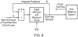
- FIG. 9 A block diagram of an example implementation of the third embodiment is shown in Figure 9 .
- the third embodiment of the enhanced fuel flow demand schedule 50 applies a more aggressive increase in fuel flow demand W f_D , from the nadir of the compressor discharge pressure P 30 , than the first embodiment and so the base fuel flow demand W f_D to which the normal, exponential, rate of increase W f_D is applied is higher.
- the fuel flow demand W f_D recovers to its pre-surge level more rapidly than the first embodiment and much more rapidly than the conventional method in which no enhanced schedule 50 was applied.
- the third embodiment of the enhanced fuel flow demand schedule 50 does not require a step of determining if the ratio of fuel flow demand W f_D to actual fuel flow W f_A is less than a threshold ratio before applying the enhanced schedule 50. Instead the calculation can be operational throughout fuel flow control but will only control the fuel flow demand W f_D in response to a surge condition 32 and when the maximum fuel flow rate limiter based on compressor discharge pressure P 30 stops being in control of the fuel flow.
- a step to determine if the fuel flow demand W f_D is less than a threshold ratio R of the actual fuel flow W f_A may be used to trigger application of the third embodiment of the enhanced fuel flow demand schedule 50.
- the method 30 is most accurate when the actual fuel flow W f_A can be measured at step 36, for example from the physical position of the fuel metering valve 74, the method 30 can also be implemented by using a simulated value of actual fuel flow W f_A . Such a simulated value may be derived from a model of the dynamic response of the fuel flow system 68.
- the method 30 enables other methods to be applied in an engine control system which have an adverse effect on surge recovery. For example some methods to detect and/or accommodate shaft break events, which have some similar characteristics to surge events, have the effect of degrading surge recovery.
- the method 30 described herein overcomes that degraded surge recovery and so makes use of both methods feasible.
- the method 30 is also applicable to marine and industrial gas turbine engines.
Landscapes
- Engineering & Computer Science (AREA)
- Chemical & Material Sciences (AREA)
- Combustion & Propulsion (AREA)
- Mechanical Engineering (AREA)
- General Engineering & Computer Science (AREA)
- Control Of Positive-Displacement Air Blowers (AREA)
Applications Claiming Priority (1)
| Application Number | Priority Date | Filing Date | Title |
|---|---|---|---|
| GBGB1601487.0A GB201601487D0 (en) | 2016-01-27 | 2016-01-27 | Fuel flow control |
Publications (2)
| Publication Number | Publication Date |
|---|---|
| EP3199784A1 true EP3199784A1 (de) | 2017-08-02 |
| EP3199784B1 EP3199784B1 (de) | 2022-03-09 |
Family
ID=55535007
Family Applications (1)
| Application Number | Title | Priority Date | Filing Date |
|---|---|---|---|
| EP17150831.0A Active EP3199784B1 (de) | 2016-01-27 | 2017-01-10 | Brennstoffdurchflusssteuerung |
Country Status (3)
| Country | Link |
|---|---|
| US (2) | US10605174B2 (de) |
| EP (1) | EP3199784B1 (de) |
| GB (1) | GB201601487D0 (de) |
Cited By (2)
| Publication number | Priority date | Publication date | Assignee | Title |
|---|---|---|---|---|
| CN110886658A (zh) * | 2018-09-11 | 2020-03-17 | 普拉特 - 惠特尼加拿大公司 | 用于检测高涡轮温度操作的方法和系统 |
| EP4682367A1 (de) * | 2024-07-15 | 2026-01-21 | Pratt & Whitney Canada Corp. | Begrenzer des relativen brennstoffverhältnisses für die druckstossrückgewinnung in gasturbinen |
Families Citing this family (5)
| Publication number | Priority date | Publication date | Assignee | Title |
|---|---|---|---|---|
| GB201601487D0 (en) * | 2016-01-27 | 2016-03-09 | Rolls Royce Plc | Fuel flow control |
| US11105269B2 (en) * | 2017-05-12 | 2021-08-31 | General Electric Company | Method of control of three spool gas turbine engine |
| US11428160B2 (en) | 2020-12-31 | 2022-08-30 | General Electric Company | Gas turbine engine with interdigitated turbine and gear assembly |
| CN115324747A (zh) * | 2022-04-20 | 2022-11-11 | 中国航发沈阳发动机研究所 | 一种涡轮发动机加减速供油方法 |
| CN114837821B (zh) * | 2022-04-29 | 2023-07-07 | 中国航发沈阳发动机研究所 | 一种航空发动机地面起动供油规律自适应调整方法及系统 |
Citations (3)
| Publication number | Priority date | Publication date | Assignee | Title |
|---|---|---|---|---|
| US4118926A (en) * | 1977-02-28 | 1978-10-10 | United Technologies Corporation | Automatic stall recovery system |
| EP0092425A1 (de) * | 1982-04-19 | 1983-10-26 | Colt Industries Inc | Brennstoffregler für Gasturbinentriebwerke |
| US20010045088A1 (en) * | 2000-05-25 | 2001-11-29 | Honda Giken Kogyo Kabushiki Kaisha | Surge detection system of gas turbine aeroengine |
Family Cites Families (10)
| Publication number | Priority date | Publication date | Assignee | Title |
|---|---|---|---|---|
| GB127426A (en) | 1918-06-17 | 1919-06-05 | Igranic Electric Co Ltd | Improvements in Electric Lock-out Switches. |
| US2851855A (en) | 1953-03-27 | 1958-09-16 | Curtiss Wright Corp | Fuel control system for jet engines |
| US4722180A (en) * | 1986-11-20 | 1988-02-02 | United Technologies Corporation | Method and means for enhancing recovery of a surge condition in a gas turbine engine |
| US5205771A (en) | 1992-02-10 | 1993-04-27 | Anson Sims | Toy bomber for generating smoke-filled bubbles |
| NO952860L (no) | 1994-08-08 | 1996-02-09 | Compressor Controls Corp | Framgangsmåte og apparat for å hindre parameterdrift i gassturbiner |
| US6148601A (en) * | 1998-05-08 | 2000-11-21 | Hamilton Sundstrand Corporation | Engine fuel control system and method |
| GB9918092D0 (en) | 1999-08-03 | 1999-10-06 | Rolls Royce Plc | Ducted fan gas turbine engine control system |
| US6655151B2 (en) * | 2001-09-07 | 2003-12-02 | Honeywell International, Inc. | Method for controlling fuel flow to a gas turbine engine |
| EP1840354B1 (de) * | 2006-03-28 | 2017-11-29 | Ansaldo Energia IP UK Limited | Verfahren zum Betrieb einer Gasturbinenanlage sowie Gasturbinenanlage zur Durchführung des Verfahrens |
| GB201601487D0 (en) * | 2016-01-27 | 2016-03-09 | Rolls Royce Plc | Fuel flow control |
-
2016
- 2016-01-27 GB GBGB1601487.0A patent/GB201601487D0/en not_active Ceased
-
2017
- 2017-01-10 US US15/403,025 patent/US10605174B2/en active Active
- 2017-01-10 EP EP17150831.0A patent/EP3199784B1/de active Active
-
2020
- 2020-02-24 US US16/798,607 patent/US11187161B2/en active Active
Patent Citations (3)
| Publication number | Priority date | Publication date | Assignee | Title |
|---|---|---|---|---|
| US4118926A (en) * | 1977-02-28 | 1978-10-10 | United Technologies Corporation | Automatic stall recovery system |
| EP0092425A1 (de) * | 1982-04-19 | 1983-10-26 | Colt Industries Inc | Brennstoffregler für Gasturbinentriebwerke |
| US20010045088A1 (en) * | 2000-05-25 | 2001-11-29 | Honda Giken Kogyo Kabushiki Kaisha | Surge detection system of gas turbine aeroengine |
Cited By (2)
| Publication number | Priority date | Publication date | Assignee | Title |
|---|---|---|---|---|
| CN110886658A (zh) * | 2018-09-11 | 2020-03-17 | 普拉特 - 惠特尼加拿大公司 | 用于检测高涡轮温度操作的方法和系统 |
| EP4682367A1 (de) * | 2024-07-15 | 2026-01-21 | Pratt & Whitney Canada Corp. | Begrenzer des relativen brennstoffverhältnisses für die druckstossrückgewinnung in gasturbinen |
Also Published As
| Publication number | Publication date |
|---|---|
| US10605174B2 (en) | 2020-03-31 |
| EP3199784B1 (de) | 2022-03-09 |
| US20170211486A1 (en) | 2017-07-27 |
| US20200191065A1 (en) | 2020-06-18 |
| GB201601487D0 (en) | 2016-03-09 |
| US11187161B2 (en) | 2021-11-30 |
Similar Documents
| Publication | Publication Date | Title |
|---|---|---|
| US11187161B2 (en) | Fuel flow control | |
| US12152540B2 (en) | Fuel control device, combustor, gas turbine, control method, and non-transitory computer-readable medium | |
| US8459038B1 (en) | Two-spool turboshaft engine control system and method | |
| JP5583697B2 (ja) | ガスタービンを制御するための方法およびシステム、ならびにこのようなシステムを含むガスタービン | |
| EP3045696A1 (de) | System und verfahren zur ladungsleistungsverwaltung in einem wellentriebwerk-gasturbinenmotor | |
| EP2778376B1 (de) | System und Verfahren zur Motorübergangsleistungsreaktion | |
| US10746104B2 (en) | Propulsion system | |
| EP3118437B1 (de) | Brennstoffregelung eines gasturbinenmotors | |
| RU2255247C1 (ru) | Способ защиты компрессора при неустойчивой работе газотурбинного двигателя | |
| US7377115B2 (en) | Approach to extending life of gas turbine engine | |
| US7111464B2 (en) | Acceleration control in multi spool gas turbine engine | |
| EP3530913A1 (de) | Steuergerät und verfahren | |
| JP6801968B2 (ja) | ガスタービンの制御装置および制御方法、並びにガスタービン | |
| Golberg et al. | Improving control reliability and quality of aircraft engines by means the software virtual engine | |
| RU2310100C2 (ru) | Способ защиты газотурбинного двигателя от возникновения неустойчивой работы компрессора | |
| RU2774566C1 (ru) | Способ управления газотурбинным двигателем с форсажной камерой сгорания | |
| RU2472974C2 (ru) | Способ защиты газотурбинного двигателя | |
| RU2345234C2 (ru) | Способ управления газотурбинным двигателем | |
| RU2427722C1 (ru) | Способ управления газотурбинной установкой | |
| RU2474713C2 (ru) | Способ защиты газотурбинного двигателя | |
| RU2493051C2 (ru) | Способ управления турбовинтовой силовой установкой самолета |
Legal Events
| Date | Code | Title | Description |
|---|---|---|---|
| PUAI | Public reference made under article 153(3) epc to a published international application that has entered the european phase |
Free format text: ORIGINAL CODE: 0009012 |
|
| STAA | Information on the status of an ep patent application or granted ep patent |
Free format text: STATUS: THE APPLICATION HAS BEEN PUBLISHED |
|
| AK | Designated contracting states |
Kind code of ref document: A1 Designated state(s): AL AT BE BG CH CY CZ DE DK EE ES FI FR GB GR HR HU IE IS IT LI LT LU LV MC MK MT NL NO PL PT RO RS SE SI SK SM TR |
|
| AX | Request for extension of the european patent |
Extension state: BA ME |
|
| STAA | Information on the status of an ep patent application or granted ep patent |
Free format text: STATUS: REQUEST FOR EXAMINATION WAS MADE |
|
| 17P | Request for examination filed |
Effective date: 20180202 |
|
| RBV | Designated contracting states (corrected) |
Designated state(s): AL AT BE BG CH CY CZ DE DK EE ES FI FR GB GR HR HU IE IS IT LI LT LU LV MC MK MT NL NO PL PT RO RS SE SI SK SM TR |
|
| RAP1 | Party data changed (applicant data changed or rights of an application transferred) |
Owner name: ROLLS-ROYCE PLC |
|
| STAA | Information on the status of an ep patent application or granted ep patent |
Free format text: STATUS: EXAMINATION IS IN PROGRESS |
|
| 17Q | First examination report despatched |
Effective date: 20200605 |
|
| GRAP | Despatch of communication of intention to grant a patent |
Free format text: ORIGINAL CODE: EPIDOSNIGR1 |
|
| STAA | Information on the status of an ep patent application or granted ep patent |
Free format text: STATUS: GRANT OF PATENT IS INTENDED |
|
| GRAS | Grant fee paid |
Free format text: ORIGINAL CODE: EPIDOSNIGR3 |
|
| INTG | Intention to grant announced |
Effective date: 20220107 |
|
| GRAA | (expected) grant |
Free format text: ORIGINAL CODE: 0009210 |
|
| STAA | Information on the status of an ep patent application or granted ep patent |
Free format text: STATUS: THE PATENT HAS BEEN GRANTED |
|
| AK | Designated contracting states |
Kind code of ref document: B1 Designated state(s): AL AT BE BG CH CY CZ DE DK EE ES FI FR GB GR HR HU IE IS IT LI LT LU LV MC MK MT NL NO PL PT RO RS SE SI SK SM TR |
|
| REG | Reference to a national code |
Ref country code: CH Ref legal event code: EP Ref country code: AT Ref legal event code: REF Ref document number: 1474332 Country of ref document: AT Kind code of ref document: T Effective date: 20220315 |
|
| REG | Reference to a national code |
Ref country code: DE Ref legal event code: R096 Ref document number: 602017054260 Country of ref document: DE |
|
| REG | Reference to a national code |
Ref country code: IE Ref legal event code: FG4D |
|
| REG | Reference to a national code |
Ref country code: LT Ref legal event code: MG9D |
|
| REG | Reference to a national code |
Ref country code: NL Ref legal event code: MP Effective date: 20220309 |
|
| PG25 | Lapsed in a contracting state [announced via postgrant information from national office to epo] |
Ref country code: SE Free format text: LAPSE BECAUSE OF FAILURE TO SUBMIT A TRANSLATION OF THE DESCRIPTION OR TO PAY THE FEE WITHIN THE PRESCRIBED TIME-LIMIT Effective date: 20220309 Ref country code: RS Free format text: LAPSE BECAUSE OF FAILURE TO SUBMIT A TRANSLATION OF THE DESCRIPTION OR TO PAY THE FEE WITHIN THE PRESCRIBED TIME-LIMIT Effective date: 20220309 Ref country code: NO Free format text: LAPSE BECAUSE OF FAILURE TO SUBMIT A TRANSLATION OF THE DESCRIPTION OR TO PAY THE FEE WITHIN THE PRESCRIBED TIME-LIMIT Effective date: 20220609 Ref country code: LT Free format text: LAPSE BECAUSE OF FAILURE TO SUBMIT A TRANSLATION OF THE DESCRIPTION OR TO PAY THE FEE WITHIN THE PRESCRIBED TIME-LIMIT Effective date: 20220309 Ref country code: HR Free format text: LAPSE BECAUSE OF FAILURE TO SUBMIT A TRANSLATION OF THE DESCRIPTION OR TO PAY THE FEE WITHIN THE PRESCRIBED TIME-LIMIT Effective date: 20220309 Ref country code: BG Free format text: LAPSE BECAUSE OF FAILURE TO SUBMIT A TRANSLATION OF THE DESCRIPTION OR TO PAY THE FEE WITHIN THE PRESCRIBED TIME-LIMIT Effective date: 20220609 |
|
| REG | Reference to a national code |
Ref country code: AT Ref legal event code: MK05 Ref document number: 1474332 Country of ref document: AT Kind code of ref document: T Effective date: 20220309 |
|
| PG25 | Lapsed in a contracting state [announced via postgrant information from national office to epo] |
Ref country code: LV Free format text: LAPSE BECAUSE OF FAILURE TO SUBMIT A TRANSLATION OF THE DESCRIPTION OR TO PAY THE FEE WITHIN THE PRESCRIBED TIME-LIMIT Effective date: 20220309 Ref country code: GR Free format text: LAPSE BECAUSE OF FAILURE TO SUBMIT A TRANSLATION OF THE DESCRIPTION OR TO PAY THE FEE WITHIN THE PRESCRIBED TIME-LIMIT Effective date: 20220610 Ref country code: FI Free format text: LAPSE BECAUSE OF FAILURE TO SUBMIT A TRANSLATION OF THE DESCRIPTION OR TO PAY THE FEE WITHIN THE PRESCRIBED TIME-LIMIT Effective date: 20220309 |
|
| PG25 | Lapsed in a contracting state [announced via postgrant information from national office to epo] |
Ref country code: NL Free format text: LAPSE BECAUSE OF FAILURE TO SUBMIT A TRANSLATION OF THE DESCRIPTION OR TO PAY THE FEE WITHIN THE PRESCRIBED TIME-LIMIT Effective date: 20220309 |
|
| PG25 | Lapsed in a contracting state [announced via postgrant information from national office to epo] |
Ref country code: SM Free format text: LAPSE BECAUSE OF FAILURE TO SUBMIT A TRANSLATION OF THE DESCRIPTION OR TO PAY THE FEE WITHIN THE PRESCRIBED TIME-LIMIT Effective date: 20220309 Ref country code: SK Free format text: LAPSE BECAUSE OF FAILURE TO SUBMIT A TRANSLATION OF THE DESCRIPTION OR TO PAY THE FEE WITHIN THE PRESCRIBED TIME-LIMIT Effective date: 20220309 Ref country code: RO Free format text: LAPSE BECAUSE OF FAILURE TO SUBMIT A TRANSLATION OF THE DESCRIPTION OR TO PAY THE FEE WITHIN THE PRESCRIBED TIME-LIMIT Effective date: 20220309 Ref country code: PT Free format text: LAPSE BECAUSE OF FAILURE TO SUBMIT A TRANSLATION OF THE DESCRIPTION OR TO PAY THE FEE WITHIN THE PRESCRIBED TIME-LIMIT Effective date: 20220711 Ref country code: ES Free format text: LAPSE BECAUSE OF FAILURE TO SUBMIT A TRANSLATION OF THE DESCRIPTION OR TO PAY THE FEE WITHIN THE PRESCRIBED TIME-LIMIT Effective date: 20220309 Ref country code: EE Free format text: LAPSE BECAUSE OF FAILURE TO SUBMIT A TRANSLATION OF THE DESCRIPTION OR TO PAY THE FEE WITHIN THE PRESCRIBED TIME-LIMIT Effective date: 20220309 Ref country code: CZ Free format text: LAPSE BECAUSE OF FAILURE TO SUBMIT A TRANSLATION OF THE DESCRIPTION OR TO PAY THE FEE WITHIN THE PRESCRIBED TIME-LIMIT Effective date: 20220309 Ref country code: AT Free format text: LAPSE BECAUSE OF FAILURE TO SUBMIT A TRANSLATION OF THE DESCRIPTION OR TO PAY THE FEE WITHIN THE PRESCRIBED TIME-LIMIT Effective date: 20220309 |
|
| PG25 | Lapsed in a contracting state [announced via postgrant information from national office to epo] |
Ref country code: PL Free format text: LAPSE BECAUSE OF FAILURE TO SUBMIT A TRANSLATION OF THE DESCRIPTION OR TO PAY THE FEE WITHIN THE PRESCRIBED TIME-LIMIT Effective date: 20220309 Ref country code: IS Free format text: LAPSE BECAUSE OF FAILURE TO SUBMIT A TRANSLATION OF THE DESCRIPTION OR TO PAY THE FEE WITHIN THE PRESCRIBED TIME-LIMIT Effective date: 20220709 Ref country code: AL Free format text: LAPSE BECAUSE OF FAILURE TO SUBMIT A TRANSLATION OF THE DESCRIPTION OR TO PAY THE FEE WITHIN THE PRESCRIBED TIME-LIMIT Effective date: 20220309 |
|
| REG | Reference to a national code |
Ref country code: DE Ref legal event code: R097 Ref document number: 602017054260 Country of ref document: DE |
|
| PLBE | No opposition filed within time limit |
Free format text: ORIGINAL CODE: 0009261 |
|
| STAA | Information on the status of an ep patent application or granted ep patent |
Free format text: STATUS: NO OPPOSITION FILED WITHIN TIME LIMIT |
|
| PG25 | Lapsed in a contracting state [announced via postgrant information from national office to epo] |
Ref country code: DK Free format text: LAPSE BECAUSE OF FAILURE TO SUBMIT A TRANSLATION OF THE DESCRIPTION OR TO PAY THE FEE WITHIN THE PRESCRIBED TIME-LIMIT Effective date: 20220309 |
|
| 26N | No opposition filed |
Effective date: 20221212 |
|
| PG25 | Lapsed in a contracting state [announced via postgrant information from national office to epo] |
Ref country code: SI Free format text: LAPSE BECAUSE OF FAILURE TO SUBMIT A TRANSLATION OF THE DESCRIPTION OR TO PAY THE FEE WITHIN THE PRESCRIBED TIME-LIMIT Effective date: 20220309 |
|
| P01 | Opt-out of the competence of the unified patent court (upc) registered |
Effective date: 20230528 |
|
| PG25 | Lapsed in a contracting state [announced via postgrant information from national office to epo] |
Ref country code: IT Free format text: LAPSE BECAUSE OF FAILURE TO SUBMIT A TRANSLATION OF THE DESCRIPTION OR TO PAY THE FEE WITHIN THE PRESCRIBED TIME-LIMIT Effective date: 20220309 |
|
| REG | Reference to a national code |
Ref country code: CH Ref legal event code: PL |
|
| PG25 | Lapsed in a contracting state [announced via postgrant information from national office to epo] |
Ref country code: LU Free format text: LAPSE BECAUSE OF NON-PAYMENT OF DUE FEES Effective date: 20230110 |
|
| REG | Reference to a national code |
Ref country code: BE Ref legal event code: MM Effective date: 20230131 |
|
| PG25 | Lapsed in a contracting state [announced via postgrant information from national office to epo] |
Ref country code: LI Free format text: LAPSE BECAUSE OF NON-PAYMENT OF DUE FEES Effective date: 20230131 Ref country code: CH Free format text: LAPSE BECAUSE OF NON-PAYMENT OF DUE FEES Effective date: 20230131 |
|
| PG25 | Lapsed in a contracting state [announced via postgrant information from national office to epo] |
Ref country code: BE Free format text: LAPSE BECAUSE OF NON-PAYMENT OF DUE FEES Effective date: 20230131 |
|
| PG25 | Lapsed in a contracting state [announced via postgrant information from national office to epo] |
Ref country code: IE Free format text: LAPSE BECAUSE OF NON-PAYMENT OF DUE FEES Effective date: 20230110 |
|
| PG25 | Lapsed in a contracting state [announced via postgrant information from national office to epo] |
Ref country code: MC Free format text: LAPSE BECAUSE OF FAILURE TO SUBMIT A TRANSLATION OF THE DESCRIPTION OR TO PAY THE FEE WITHIN THE PRESCRIBED TIME-LIMIT Effective date: 20220309 |
|
| PG25 | Lapsed in a contracting state [announced via postgrant information from national office to epo] |
Ref country code: MC Free format text: LAPSE BECAUSE OF FAILURE TO SUBMIT A TRANSLATION OF THE DESCRIPTION OR TO PAY THE FEE WITHIN THE PRESCRIBED TIME-LIMIT Effective date: 20220309 |
|
| PGFP | Annual fee paid to national office [announced via postgrant information from national office to epo] |
Ref country code: DE Payment date: 20250129 Year of fee payment: 9 |
|
| PGFP | Annual fee paid to national office [announced via postgrant information from national office to epo] |
Ref country code: FR Payment date: 20250127 Year of fee payment: 9 |
|
| PGFP | Annual fee paid to national office [announced via postgrant information from national office to epo] |
Ref country code: GB Payment date: 20250121 Year of fee payment: 9 |
|
| PG25 | Lapsed in a contracting state [announced via postgrant information from national office to epo] |
Ref country code: CY Free format text: LAPSE BECAUSE OF FAILURE TO SUBMIT A TRANSLATION OF THE DESCRIPTION OR TO PAY THE FEE WITHIN THE PRESCRIBED TIME-LIMIT; INVALID AB INITIO Effective date: 20170110 |
|
| PG25 | Lapsed in a contracting state [announced via postgrant information from national office to epo] |
Ref country code: HU Free format text: LAPSE BECAUSE OF FAILURE TO SUBMIT A TRANSLATION OF THE DESCRIPTION OR TO PAY THE FEE WITHIN THE PRESCRIBED TIME-LIMIT; INVALID AB INITIO Effective date: 20170110 |
|
| PG25 | Lapsed in a contracting state [announced via postgrant information from national office to epo] |
Ref country code: TR Free format text: LAPSE BECAUSE OF FAILURE TO SUBMIT A TRANSLATION OF THE DESCRIPTION OR TO PAY THE FEE WITHIN THE PRESCRIBED TIME-LIMIT Effective date: 20220309 |