EP0092425A1 - Brennstoffregler für Gasturbinentriebwerke - Google Patents
Brennstoffregler für Gasturbinentriebwerke Download PDFInfo
- Publication number
- EP0092425A1 EP0092425A1 EP83302208A EP83302208A EP0092425A1 EP 0092425 A1 EP0092425 A1 EP 0092425A1 EP 83302208 A EP83302208 A EP 83302208A EP 83302208 A EP83302208 A EP 83302208A EP 0092425 A1 EP0092425 A1 EP 0092425A1
- Authority
- EP
- European Patent Office
- Prior art keywords
- gas generator
- engine
- rate
- discharge pressure
- speed
- Prior art date
- Legal status (The legal status is an assumption and is not a legal conclusion. Google has not performed a legal analysis and makes no representation as to the accuracy of the status listed.)
- Granted
Links
- 239000000446 fuel Substances 0.000 title claims abstract description 56
- 230000001133 acceleration Effects 0.000 claims abstract description 31
- 230000008859 change Effects 0.000 claims abstract description 20
- 238000000034 method Methods 0.000 claims abstract description 9
- 238000013500 data storage Methods 0.000 claims description 2
- 230000001419 dependent effect Effects 0.000 claims description 2
- 230000004048 modification Effects 0.000 claims description 2
- 238000012986 modification Methods 0.000 claims description 2
- 230000006870 function Effects 0.000 description 17
- 230000008901 benefit Effects 0.000 description 3
- 238000011084 recovery Methods 0.000 description 3
- 230000003247 decreasing effect Effects 0.000 description 2
- 230000004044 response Effects 0.000 description 2
- 230000007812 deficiency Effects 0.000 description 1
- 230000006866 deterioration Effects 0.000 description 1
- 238000010586 diagram Methods 0.000 description 1
- 238000005516 engineering process Methods 0.000 description 1
- 230000006872 improvement Effects 0.000 description 1
- 230000009467 reduction Effects 0.000 description 1
- 238000004088 simulation Methods 0.000 description 1
- 238000006467 substitution reaction Methods 0.000 description 1
Images

Classifications
-
- F—MECHANICAL ENGINEERING; LIGHTING; HEATING; WEAPONS; BLASTING
- F02—COMBUSTION ENGINES; HOT-GAS OR COMBUSTION-PRODUCT ENGINE PLANTS
- F02C—GAS-TURBINE PLANTS; AIR INTAKES FOR JET-PROPULSION PLANTS; CONTROLLING FUEL SUPPLY IN AIR-BREATHING JET-PROPULSION PLANTS
- F02C9/00—Controlling gas-turbine plants; Controlling fuel supply in air- breathing jet-propulsion plants
- F02C9/26—Control of fuel supply
- F02C9/28—Regulating systems responsive to plant or ambient parameters, e.g. temperature, pressure, rotor speed
-
- F—MECHANICAL ENGINEERING; LIGHTING; HEATING; WEAPONS; BLASTING
- F05—INDEXING SCHEMES RELATING TO ENGINES OR PUMPS IN VARIOUS SUBCLASSES OF CLASSES F01-F04
- F05D—INDEXING SCHEME FOR ASPECTS RELATING TO NON-POSITIVE-DISPLACEMENT MACHINES OR ENGINES, GAS-TURBINES OR JET-PROPULSION PLANTS
- F05D2270/00—Control
- F05D2270/01—Purpose of the control system
- F05D2270/04—Purpose of the control system to control acceleration (u)
-
- F—MECHANICAL ENGINEERING; LIGHTING; HEATING; WEAPONS; BLASTING
- F05—INDEXING SCHEMES RELATING TO ENGINES OR PUMPS IN VARIOUS SUBCLASSES OF CLASSES F01-F04
- F05D—INDEXING SCHEME FOR ASPECTS RELATING TO NON-POSITIVE-DISPLACEMENT MACHINES OR ENGINES, GAS-TURBINES OR JET-PROPULSION PLANTS
- F05D2270/00—Control
- F05D2270/01—Purpose of the control system
- F05D2270/10—Purpose of the control system to cope with, or avoid, compressor flow instabilities
- F05D2270/101—Compressor surge or stall
Definitions
- the present invention relates to the exercise of control over gas turbine engines and particularly to controlling the rate of delivery of fuel to the gas generator of a free turbine engine which may, for example,be employed as the power plant for a rotary wing aircraft.
- surge i.e., a mismatch in the speed of the compressor blades and the incoming air.
- surge condition occurs there is a large loss of power, a loss of air flow, an increase in temperature and substantial mechanical vibration.
- the surge condition is usually encountered during engine acceleration when the rate of delivery of fuel to the gas generator becomes excessive.
- Prior art gas turbine engine controls may be generally characterized as being of either the "open” or “closed” loop type.
- Open loop controls are scheduling devices wherein the fuel flow to the engine is varied as a function of speed.
- Prior closed loop gas turbine engine controls are insensitive to changes in the fuel control itself, changes in the engine or changes in the characteristics of the fuel being supplied to the engine.
- Prior closed loop gas turbine engine fuel controls typically operate in a mode wherein the rate of change of the gas generator shaft speed is determined and fuel flow to the engine is varied so as to match schedules devised when the engine was new.
- the prior art closed loop control may have a speed governor which, under steady state conditions, demands a fuel flow as a function of gas generator speed.
- the control will also have an acceleration schedule which will set the fuel flow rate during acceleration.
- a surge margin will be built into the acceleration schedule. Because of this surge margin, the accelerating engine will be able to accept a predetermined percent of additional fuel flow before it will enter the surge condition. Since the engine and/or fuel control may undergo changes in operating characteristics with extended use, the surge margin may actually decrease with time. If excess fuel is delivered to the engine when it is in the surge condition, for example because the surge margin has decreased and thus the acceleration schedule is actually calling for excess fuel, it is possible that the engine will either stay in surge or be subjected to multiple surges.
- a method of controlling the rate of delivery of a combustible fuel to a gas turbine engine, the engine having a gas generator and being operable in substantially steady state and acceleration modes, comprising:
- the invention provides an apparatus for controlling the rate of delivery of a combustible fuel to a gas turbine engine, the engine having a gas generator and being operable in substantially steady state and acceleration modes, comprising;
- the present invention overcomes the above briefly discussed and other deficiencies and disadvantages of the prior art by providing a novel and improved gas turbine engine fuel control operating mode which is characterized by significantly enhanced ability of the engine to recover smoothly from surge. Further, the control technique of this invention is substantially immune to surge margin loss resulting from fuel control deterioration or damage.
- fuel flow to the gas generator of a gas turbine engine is varied such that the ratio of the rate of change of gas generator speed to compressor discharge pressure satisfies the fuel control's demand.
- Apparatus in accordance with the present invention comprises a closed loop electronic fuel control wherein, during acceleration, fuel flow to the gas turbine engine will be manipulated to meet the scheduled function of the ratio of the rate of change of gas generator speed over gas generator compressor discharge pressure to corrected gas generator speed.
- This scheduled acceleration NDOT/CDP will be varied as a function of actual sensed CDP.
- an NDOT/CDP signal which is a function of either gas generator or power turbine speed error will be selected as the fuel flow control signal.
- the selected NDOT/CDP command will be varied in the same manner as the acceleration NDOT/CDP signal by a signal commensurate with the actual compressor discharge pressure to produce an NDOT signal.
- NDOT error signal is nulled through an integral plus proportional NDOT governor which operates through fuel flow per compressor discharge pressure ratio units.
- the commanded fuel flow to the engine is computed as a function of the output of the NDOT governor and CDP.
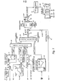
- Engine 10 for purposes of explanation, may be considered to be a free turbine type engine comprising a gas generator and a free turbine which is driven by, but mechanically decoupled from, the gas generator.
- engine 10 will be instrumented so as to provide, among other information, signals commensurate with gas generator speed NG, compressor discharge pressure CDP, power turbine speed NP and compressor inlet temperature T2.
- the aforementioned signals will comprise inputs to the electronic fuel control of the present invention.
- An additional input to the fuel control will comprise a PLA signal commensurate with the angle or setting of the pilot's power lever.
- the engine manufacturer will provide information commensurate with the desired gas generator speed NG * , i.e., the gas generator speed demand, corresponding to each setting of the pilot's power lever. This information will be stored in a first memory, i.e., a look-up table, 12.
- the engine manufacturer will also provide information from which an acceleration schedule, with an appropriate surge margin, may be determined. This acceleration schedule will comprise a plot of NDOT/CDP versus NG/ ⁇ .
- the acceleration schedule will also be stored in a memory, i.e., a second look-up table, 14.
- the PLA signal is employed to address memory 12 whereby the NG * signal commensurate with PLA will be read out of the memory and applied as a first input to a summing circuit 16.
- the second input to summer 16 will be the actual NG signal derived from the engine sensor.
- the output of summer 16. will thus be an NG error signal which is delivered as an input to a gas producer speed governor 18.
- the actual circuitry comprising governor 18 will depend upon the characteristics of engine 10. Typically, governor 18 will be a lead-lag circuit which produces an output signal which results in the fuel control being responsive and stable over the entire flight envelope. Such governors are well known in the art.
- the output of governor 18 will be an NDOT'/CDP signal which is a function of gas producer speed error. This error signal, when compensated for the dynamics of the fuel control and engine, comprises an NDOT/CDP signal because of the gain of the governor 18.
- the NDOT'/CDP signal from governor 18 is delivered as a first input to a first auctioneering circuit 20.
- a second input to circuit 20, which functions as a "least wins" gate, comprises an NDOT"/CDP signal which is a function of power turbine speed error.
- the NDOT"/CDP signal is produced by summing, at a summing juction 22, the actual power turbine speed NP with a power turbine speed reference NP * provided by a cockpit instrumentation input.
- the NP error signal produced by summer 22 is delivered as an input to a power turbine governor 24.
- Governor 24 is a second dynamic compensation circuit which causes the NDOT"/CDP signal to vary as required to ensure that, in the power turbine speed error governing mode, the fuel control will be stable and responsive.
- Governor 24 may, for example, include a notch filter with a first order lag.
- the third input to auctioneering circuit 20 is an NDOT/CDP signal derived from the acceleration schedule stored in memory 14.
- the memory is addressed by the NG/ ⁇ signal provided by dividing, in a division circuit 26, the signal commensurate with sensed gas generator speed by the ⁇ signal provided, in response to the T2 input, by an inlet temperature correcting circuit 27.
- auctioneering circuit 20 selects, for passage, that one of the input signals thereto which represents the lowest demanded NDOT/CDP.
- the selected NDOT/CDP signal is applied as a first input to a "highest wins" gate 28.
- the second input to gate 28 is an NDOT"'/CDP signal derived from a deceleration schedule, based on engine manufacturer supplied data, stored in a memory 29. Memory 29 is addressed by the NG/ ⁇ signal provided by divider 26.
- Gate 28 passes that one of the input signals thereto which represents the higher demanded NDOT/CDP to a multiplier 30.
- the second input to multiplier 30 is the actual sensed CDP signal. Accordingly, multiplier 30 provides, to a summing junction 31, an NDOT * demand signal.
- the NG signal is also applied to a differentiator 32 to thereby provide an actual NDOT signal which is delivered as a second input to summing junction 31.
- Algebraic summation of the NDOT * and NDOT signals produces an NDOT error signal which is simultaneously delivered to a proportional gain compensation circuit 34 and integral gain compensation circuit 36.
- the compensation circuits 34 and 36 comprise an NDOT governor which operates through fuel flow/compressor discharge pressure ratio units.
- the WF/CDP signal from summing junction 38 is applied as a first input to an altitude compensation circuit 40 which may comprise a multiplier.
- the second input to the altitude compensation circuit 40 is the actual CDP signal.
- the output of compensation circuit 40 is a signal which corresponds to the selected fuel flow demand WF * .
- a metering device 42 causes delivery of a fuel flow WF to engine 10.
- NDOT/CDP mode of control takes advantage of the NDOT characteristics of the engine while including altitude compensation and surge recovery, the latter being a result of the use of the compressor discharge pressure as an NDOT scheduling parameter rather than merely for altitude compensation purposes.
- Surge recovery is further enhanced since operating the NDOT error signal through WF/CDP results in decreasing fuel flow with the drop in compressor discharge pressure resulting from an engine surge. Since the drop in CDP resulting from an engine surge is a measure of the severity of the surge, controlling on CDP in accordance with the present invention results in the reduction of fuel flow produced when a surge occurs being proportional to the severity of the initial surge.
- FIG. 2 is a graphical comparison of the operation of the present invention with that of a prior closed loop electronic fuel control where compressor inlet pressure, PT2, rather than CDP was a fuel flow rate modifying input parameter.
- FIG. 2 compares gas generator speed, fuel flow, gas temperature and compressor discharge pressure for a simulation of the operation of the same engine, under the two modes of control, during acceleration. The comparison of the compressor discharge pressure under the two modes of operation is particularly significant.
- the present invention is clearly a substantial improvement over the prior art.
- a fuel flow demand which is a function of NDOT is varied as a function of the instantaneous CDP to provide a closed loop control mode that inherently optimizes surge recovery and minimizes the likelihood of multiple or hung surges.
- the control mode of the present invention is particularly well suited to implementation using existing microprocessor technology for selecting the appropriate points on an acceleration schedule and steady state fuel flow schedule.
Landscapes
- Engineering & Computer Science (AREA)
- Chemical & Material Sciences (AREA)
- Combustion & Propulsion (AREA)
- Mechanical Engineering (AREA)
- General Engineering & Computer Science (AREA)
- Electrical Control Of Air Or Fuel Supplied To Internal-Combustion Engine (AREA)
- Control Of Turbines (AREA)
Applications Claiming Priority (2)
| Application Number | Priority Date | Filing Date | Title |
|---|---|---|---|
| US06/369,530 US4470118A (en) | 1982-04-19 | 1982-04-19 | Gas turbine engine fuel control |
| US369530 | 1982-04-19 |
Publications (2)
| Publication Number | Publication Date |
|---|---|
| EP0092425A1 true EP0092425A1 (de) | 1983-10-26 |
| EP0092425B1 EP0092425B1 (de) | 1988-06-22 |
Family
ID=23455851
Family Applications (1)
| Application Number | Title | Priority Date | Filing Date |
|---|---|---|---|
| EP83302208A Expired EP0092425B1 (de) | 1982-04-19 | 1983-04-19 | Brennstoffregler für Gasturbinentriebwerke |
Country Status (4)
| Country | Link |
|---|---|
| US (1) | US4470118A (de) |
| EP (1) | EP0092425B1 (de) |
| CA (1) | CA1193694A (de) |
| DE (1) | DE3377151D1 (de) |
Cited By (7)
| Publication number | Priority date | Publication date | Assignee | Title |
|---|---|---|---|---|
| DE3830805A1 (de) * | 1988-09-09 | 1990-03-22 | Mtu Muenchen Gmbh | Regelverfahren |
| EP0306064A3 (de) * | 1987-09-03 | 1990-08-29 | The Boeing Company | Koordinierter Vortriebsregler eines Düsentriebwerkes |
| EP0392965A1 (de) * | 1989-04-10 | 1990-10-17 | United Technologies Corporation | Vorrichtung und Verfahren zur dynamischen Kompensation von Verstelleinrichtungen für den Blattanstellwinkel und die Drehzahl von Verstelluftschrauben |
| EP0419402A1 (de) * | 1989-09-20 | 1991-03-27 | United Technologies Corporation | Dynamische Kompensation des Beschleunigungsprogrammes |
| EP1312780A3 (de) * | 2001-11-16 | 2009-10-07 | Goodrich Pump & Engine Control Systems, Inc. | Kraftstoffregelungssystem für Gasturbinen |
| EP1911949A3 (de) * | 2006-10-13 | 2016-02-24 | Rolls-Royce plc | Steuerungssystem für eine Gasturbine |
| EP3199784A1 (de) * | 2016-01-27 | 2017-08-02 | Rolls-Royce plc | Brennstoffdurchflusssteuerung |
Families Citing this family (18)
| Publication number | Priority date | Publication date | Assignee | Title |
|---|---|---|---|---|
| GB8320319D0 (en) * | 1983-07-28 | 1983-09-01 | Lucas Ind Plc | Fuel control system |
| US4651518A (en) * | 1984-12-18 | 1987-03-24 | United Technologies Corporation | Transient derivative scheduling control system |
| US4783957A (en) * | 1986-12-23 | 1988-11-15 | Sundstrand Corporation | Fuel control circuit for a turbine engine |
| US5361579A (en) * | 1993-06-01 | 1994-11-08 | Sundstrand Corporation | Turbojet fuel control system |
| US5732546A (en) * | 1996-07-19 | 1998-03-31 | General Electric Company | Transient turbine overtemperature control |
| US6133643A (en) * | 1997-10-07 | 2000-10-17 | Caterpillar Inc. | Method for determining governor gains for a fuel control system |
| US6463730B1 (en) * | 2000-07-12 | 2002-10-15 | Honeywell Power Systems Inc. | Valve control logic for gas turbine recuperator |
| US6873887B2 (en) * | 2001-11-13 | 2005-03-29 | Goodrich Pump & Engine Control Systems, Inc. | Rotor torque anticipator |
| US6609378B2 (en) * | 2002-01-17 | 2003-08-26 | Honeywell International Inc. | Energy based fuel control system for gas turbine engines running on multiple fuel types |
| US20090044542A1 (en) * | 2007-08-17 | 2009-02-19 | General Electric Company | Apparatus and method for monitoring compressor clearance and controlling a gas turbine |
| US8276363B2 (en) * | 2010-08-10 | 2012-10-02 | General Electric Company | Method for compensating for combustion efficiency in fuel control system |
| FR2972233B1 (fr) * | 2011-03-04 | 2017-10-20 | Snecma | Procede de suppression du decollement tournant dans une turbomachine |
| FR2986572B1 (fr) * | 2012-02-07 | 2016-04-29 | Eurocopter France | Procede automatique de regulation d'un groupe de motorisation d'aeronef, dispositif et aeronef |
| US10036325B2 (en) * | 2016-03-30 | 2018-07-31 | General Electric Company | Variable flow compressor of a gas turbine |
| US11280683B2 (en) | 2017-05-31 | 2022-03-22 | Pratt & Whitney Canada Corp. | Method and system for detecting high turbine temperature operations |
| US11920521B2 (en) * | 2022-02-07 | 2024-03-05 | General Electric Company | Turboshaft load control using feedforward and feedback control |
| CN115075954B (zh) * | 2022-05-23 | 2023-03-28 | 蓝箭航天空间科技股份有限公司 | 提高发动机启动成功率的方法及装置 |
| US20260015978A1 (en) * | 2024-07-15 | 2026-01-15 | Pratt & Whitney Canada Corp. | Relative Fuel Ratio Unit Limiter for Gas Turbine Surge Recovery |
Citations (4)
| Publication number | Priority date | Publication date | Assignee | Title |
|---|---|---|---|---|
| US3971208A (en) * | 1974-04-01 | 1976-07-27 | The Garrett Corporation | Gas turbine fuel control |
| GB1519144A (en) * | 1974-07-09 | 1978-07-26 | Lucas Industries Ltd | Electronic fuel control for a gas turbine engine |
| GB2052805A (en) * | 1979-06-29 | 1981-01-28 | Smiths Industries Ltd | Gas-turbine engine control |
| EP0025406A1 (de) * | 1979-08-23 | 1981-03-18 | United Technologies Corporation | System und Verfahren zur elektronischen Brennstoffregelung |
Family Cites Families (5)
| Publication number | Priority date | Publication date | Assignee | Title |
|---|---|---|---|---|
| US2974483A (en) * | 1956-09-28 | 1961-03-14 | John C Sanders | Acceleration control for gas turbine engines with compressor surge limiting |
| US3307352A (en) * | 1964-01-15 | 1967-03-07 | United Aircraft Corp | Fuel control |
| US3482396A (en) * | 1967-08-17 | 1969-12-09 | Gen Motors Corp | Electronic fuel control system |
| US3939649A (en) * | 1971-02-01 | 1976-02-24 | Chandler Evans Inc. | Fuel control |
| US4117668A (en) * | 1975-11-19 | 1978-10-03 | United Technologies Corporation | Stall detector for gas turbine engine |
-
1982
- 1982-04-19 US US06/369,530 patent/US4470118A/en not_active Expired - Lifetime
-
1983
- 1983-04-18 CA CA000426109A patent/CA1193694A/en not_active Expired
- 1983-04-19 DE DE8383302208T patent/DE3377151D1/de not_active Expired
- 1983-04-19 EP EP83302208A patent/EP0092425B1/de not_active Expired
Patent Citations (4)
| Publication number | Priority date | Publication date | Assignee | Title |
|---|---|---|---|---|
| US3971208A (en) * | 1974-04-01 | 1976-07-27 | The Garrett Corporation | Gas turbine fuel control |
| GB1519144A (en) * | 1974-07-09 | 1978-07-26 | Lucas Industries Ltd | Electronic fuel control for a gas turbine engine |
| GB2052805A (en) * | 1979-06-29 | 1981-01-28 | Smiths Industries Ltd | Gas-turbine engine control |
| EP0025406A1 (de) * | 1979-08-23 | 1981-03-18 | United Technologies Corporation | System und Verfahren zur elektronischen Brennstoffregelung |
Cited By (10)
| Publication number | Priority date | Publication date | Assignee | Title |
|---|---|---|---|---|
| EP0306064A3 (de) * | 1987-09-03 | 1990-08-29 | The Boeing Company | Koordinierter Vortriebsregler eines Düsentriebwerkes |
| DE3830805A1 (de) * | 1988-09-09 | 1990-03-22 | Mtu Muenchen Gmbh | Regelverfahren |
| EP0358139A3 (de) * | 1988-09-09 | 1991-05-29 | Mtu Motoren- Und Turbinen-Union MàNchen Gmbh | Regelverfahren und Regeleinheit |
| EP0392965A1 (de) * | 1989-04-10 | 1990-10-17 | United Technologies Corporation | Vorrichtung und Verfahren zur dynamischen Kompensation von Verstelleinrichtungen für den Blattanstellwinkel und die Drehzahl von Verstelluftschrauben |
| EP0419402A1 (de) * | 1989-09-20 | 1991-03-27 | United Technologies Corporation | Dynamische Kompensation des Beschleunigungsprogrammes |
| EP1312780A3 (de) * | 2001-11-16 | 2009-10-07 | Goodrich Pump & Engine Control Systems, Inc. | Kraftstoffregelungssystem für Gasturbinen |
| EP1911949A3 (de) * | 2006-10-13 | 2016-02-24 | Rolls-Royce plc | Steuerungssystem für eine Gasturbine |
| EP3199784A1 (de) * | 2016-01-27 | 2017-08-02 | Rolls-Royce plc | Brennstoffdurchflusssteuerung |
| US10605174B2 (en) | 2016-01-27 | 2020-03-31 | Rolls-Royce Plc | Fuel flow control |
| US11187161B2 (en) | 2016-01-27 | 2021-11-30 | Rolls-Royce Plc | Fuel flow control |
Also Published As
| Publication number | Publication date |
|---|---|
| US4470118A (en) | 1984-09-04 |
| DE3377151D1 (en) | 1988-07-28 |
| EP0092425B1 (de) | 1988-06-22 |
| CA1193694A (en) | 1985-09-17 |
Similar Documents
| Publication | Publication Date | Title |
|---|---|---|
| US4470118A (en) | Gas turbine engine fuel control | |
| US4242864A (en) | Integrated control system for a gas turbine engine | |
| US3932058A (en) | Control system for variable pitch fan propulsor | |
| US5315819A (en) | Power management system for turbine engines | |
| CA1172730A (en) | Fuel control system for gas turbine engine | |
| EP1302669B1 (de) | Kontrollsystem der Position einer Einlassleitschaufel | |
| EP0092426B1 (de) | Anpassbare Gasturbinenbeschleunigungssteuerung | |
| US5083277A (en) | Fuel control system | |
| US5023793A (en) | Apparatus and method for dynamic compensation of a propeller pitch speed control governor | |
| US4928482A (en) | Control of high compressor vanes and fuel for a gas turbine engine | |
| US4625510A (en) | Stress limiter apparatus for a gas turbine engine | |
| EP0187114B1 (de) | Transiente Abblasregelung für einen Gasturbinenmotor | |
| US4449360A (en) | Stall detector and surge prevention feature for a gas turbine engine | |
| EP0412127A4 (en) | Method and system for controlling variable compressor geometry | |
| EP0092502A1 (de) | Kraftstoffsteuerung zum Steuern der Rotor-/Turbinenbeschleunigung von Helikoptern | |
| US5379583A (en) | Closed loop stator vane control | |
| EP0363301A1 (de) | Steuervorrichtung für Gasturbinenanlagen | |
| GB2088961A (en) | Fuel control system for a gas turbine engine | |
| US4432201A (en) | Acceleration limit reset | |
| US4206597A (en) | Fan R.P.M. control loop stabilization using high rotor speed | |
| US4507915A (en) | Stall detector and surge prevention feature for a gas turbine engine | |
| US4593523A (en) | Method and apparatus for acceleration limiting a gas turbine engine | |
| CA1177265A (en) | Acceleration limit reset | |
| GB1575360A (en) | Turbomachine bleed control systems | |
| US5274558A (en) | Apparatus for decoupling a torque loop from a speed loop in a power management system for turboprop engines |
Legal Events
| Date | Code | Title | Description |
|---|---|---|---|
| PUAI | Public reference made under article 153(3) epc to a published international application that has entered the european phase |
Free format text: ORIGINAL CODE: 0009012 |
|
| AK | Designated contracting states |
Designated state(s): DE FR GB IT |
|
| 17P | Request for examination filed |
Effective date: 19840327 |
|
| RAP1 | Party data changed (applicant data changed or rights of an application transferred) |
Owner name: COLT INDUSTRIES INC. |
|
| RAP3 | Party data changed (applicant data changed or rights of an application transferred) |
Owner name: COLT INDUSTRIES INC |
|
| RAP1 | Party data changed (applicant data changed or rights of an application transferred) |
Owner name: COLT INDUSTRIES INC |
|
| GRAA | (expected) grant |
Free format text: ORIGINAL CODE: 0009210 |
|
| ITF | It: translation for a ep patent filed | ||
| AK | Designated contracting states |
Kind code of ref document: B1 Designated state(s): DE FR GB IT |
|
| REF | Corresponds to: |
Ref document number: 3377151 Country of ref document: DE Date of ref document: 19880728 |
|
| ET | Fr: translation filed | ||
| PLBE | No opposition filed within time limit |
Free format text: ORIGINAL CODE: 0009261 |
|
| STAA | Information on the status of an ep patent application or granted ep patent |
Free format text: STATUS: NO OPPOSITION FILED WITHIN TIME LIMIT |
|
| 26N | No opposition filed | ||
| ITTA | It: last paid annual fee | ||
| REG | Reference to a national code |
Ref country code: GB Ref legal event code: IF02 |
|
| PGFP | Annual fee paid to national office [announced via postgrant information from national office to epo] |
Ref country code: FR Payment date: 20020401 Year of fee payment: 20 |
|
| PGFP | Annual fee paid to national office [announced via postgrant information from national office to epo] |
Ref country code: GB Payment date: 20020416 Year of fee payment: 20 |
|
| PGFP | Annual fee paid to national office [announced via postgrant information from national office to epo] |
Ref country code: DE Payment date: 20020418 Year of fee payment: 20 |
|
| PG25 | Lapsed in a contracting state [announced via postgrant information from national office to epo] |
Ref country code: GB Free format text: LAPSE BECAUSE OF EXPIRATION OF PROTECTION Effective date: 20030418 |
|
| REG | Reference to a national code |
Ref country code: GB Ref legal event code: PE20 |