EP3199780A1 - Container-type compressed air storage power generation device - Google Patents
Container-type compressed air storage power generation device Download PDFInfo
- Publication number
- EP3199780A1 EP3199780A1 EP15843216.1A EP15843216A EP3199780A1 EP 3199780 A1 EP3199780 A1 EP 3199780A1 EP 15843216 A EP15843216 A EP 15843216A EP 3199780 A1 EP3199780 A1 EP 3199780A1
- Authority
- EP
- European Patent Office
- Prior art keywords
- container
- heat storage
- heat
- power generation
- generation device
- Prior art date
- Legal status (The legal status is an assumption and is not a legal conclusion. Google has not performed a legal analysis and makes no representation as to the accuracy of the status listed.)
- Granted
Links
Images





Classifications
-
- F—MECHANICAL ENGINEERING; LIGHTING; HEATING; WEAPONS; BLASTING
- F02—COMBUSTION ENGINES; HOT-GAS OR COMBUSTION-PRODUCT ENGINE PLANTS
- F02G—HOT GAS OR COMBUSTION-PRODUCT POSITIVE-DISPLACEMENT ENGINE PLANTS; USE OF WASTE HEAT OF COMBUSTION ENGINES; NOT OTHERWISE PROVIDED FOR
- F02G1/00—Hot gas positive-displacement engine plants
- F02G1/04—Hot gas positive-displacement engine plants of closed-cycle type
- F02G1/043—Hot gas positive-displacement engine plants of closed-cycle type the engine being operated by expansion and contraction of a mass of working gas which is heated and cooled in one of a plurality of constantly communicating expansible chambers, e.g. Stirling cycle type engines
- F02G1/053—Component parts or details
- F02G1/055—Heaters or coolers
-
- F—MECHANICAL ENGINEERING; LIGHTING; HEATING; WEAPONS; BLASTING
- F02—COMBUSTION ENGINES; HOT-GAS OR COMBUSTION-PRODUCT ENGINE PLANTS
- F02C—GAS-TURBINE PLANTS; AIR INTAKES FOR JET-PROPULSION PLANTS; CONTROLLING FUEL SUPPLY IN AIR-BREATHING JET-PROPULSION PLANTS
- F02C6/00—Plural gas-turbine plants; Combinations of gas-turbine plants with other apparatus; Adaptations of gas-turbine plants for special use
- F02C6/14—Gas-turbine plants having means for storing energy, e.g. for meeting peak loads
- F02C6/16—Gas-turbine plants having means for storing energy, e.g. for meeting peak loads for storing compressed air
-
- F—MECHANICAL ENGINEERING; LIGHTING; HEATING; WEAPONS; BLASTING
- F02—COMBUSTION ENGINES; HOT-GAS OR COMBUSTION-PRODUCT ENGINE PLANTS
- F02C—GAS-TURBINE PLANTS; AIR INTAKES FOR JET-PROPULSION PLANTS; CONTROLLING FUEL SUPPLY IN AIR-BREATHING JET-PROPULSION PLANTS
- F02C7/00—Features, components parts, details or accessories, not provided for in, or of interest apart form groups F02C1/00 - F02C6/00; Air intakes for jet-propulsion plants
- F02C7/08—Heating air supply before combustion, e.g. by exhaust gases
- F02C7/10—Heating air supply before combustion, e.g. by exhaust gases by means of regenerative heat-exchangers
-
- F—MECHANICAL ENGINEERING; LIGHTING; HEATING; WEAPONS; BLASTING
- F02—COMBUSTION ENGINES; HOT-GAS OR COMBUSTION-PRODUCT ENGINE PLANTS
- F02G—HOT GAS OR COMBUSTION-PRODUCT POSITIVE-DISPLACEMENT ENGINE PLANTS; USE OF WASTE HEAT OF COMBUSTION ENGINES; NOT OTHERWISE PROVIDED FOR
- F02G1/00—Hot gas positive-displacement engine plants
- F02G1/04—Hot gas positive-displacement engine plants of closed-cycle type
- F02G1/043—Hot gas positive-displacement engine plants of closed-cycle type the engine being operated by expansion and contraction of a mass of working gas which is heated and cooled in one of a plurality of constantly communicating expansible chambers, e.g. Stirling cycle type engines
- F02G1/045—Controlling
-
- F—MECHANICAL ENGINEERING; LIGHTING; HEATING; WEAPONS; BLASTING
- F17—STORING OR DISTRIBUTING GASES OR LIQUIDS
- F17C—VESSELS FOR CONTAINING OR STORING COMPRESSED, LIQUEFIED OR SOLIDIFIED GASES; FIXED-CAPACITY GAS-HOLDERS; FILLING VESSELS WITH, OR DISCHARGING FROM VESSELS, COMPRESSED, LIQUEFIED, OR SOLIDIFIED GASES
- F17C1/00—Pressure vessels, e.g. gas cylinder, gas tank, replaceable cartridge
-
- F—MECHANICAL ENGINEERING; LIGHTING; HEATING; WEAPONS; BLASTING
- F02—COMBUSTION ENGINES; HOT-GAS OR COMBUSTION-PRODUCT ENGINE PLANTS
- F02G—HOT GAS OR COMBUSTION-PRODUCT POSITIVE-DISPLACEMENT ENGINE PLANTS; USE OF WASTE HEAT OF COMBUSTION ENGINES; NOT OTHERWISE PROVIDED FOR
- F02G2280/00—Output delivery
- F02G2280/50—Compressors or pumps
-
- F—MECHANICAL ENGINEERING; LIGHTING; HEATING; WEAPONS; BLASTING
- F17—STORING OR DISTRIBUTING GASES OR LIQUIDS
- F17C—VESSELS FOR CONTAINING OR STORING COMPRESSED, LIQUEFIED OR SOLIDIFIED GASES; FIXED-CAPACITY GAS-HOLDERS; FILLING VESSELS WITH, OR DISCHARGING FROM VESSELS, COMPRESSED, LIQUEFIED, OR SOLIDIFIED GASES
- F17C2201/00—Vessel construction, in particular geometry, arrangement or size
- F17C2201/01—Shape
- F17C2201/0104—Shape cylindrical
- F17C2201/0109—Shape cylindrical with exteriorly curved end-piece
-
- F—MECHANICAL ENGINEERING; LIGHTING; HEATING; WEAPONS; BLASTING
- F17—STORING OR DISTRIBUTING GASES OR LIQUIDS
- F17C—VESSELS FOR CONTAINING OR STORING COMPRESSED, LIQUEFIED OR SOLIDIFIED GASES; FIXED-CAPACITY GAS-HOLDERS; FILLING VESSELS WITH, OR DISCHARGING FROM VESSELS, COMPRESSED, LIQUEFIED, OR SOLIDIFIED GASES
- F17C2201/00—Vessel construction, in particular geometry, arrangement or size
- F17C2201/05—Size
- F17C2201/054—Size medium (>1 m3)
-
- F—MECHANICAL ENGINEERING; LIGHTING; HEATING; WEAPONS; BLASTING
- F17—STORING OR DISTRIBUTING GASES OR LIQUIDS
- F17C—VESSELS FOR CONTAINING OR STORING COMPRESSED, LIQUEFIED OR SOLIDIFIED GASES; FIXED-CAPACITY GAS-HOLDERS; FILLING VESSELS WITH, OR DISCHARGING FROM VESSELS, COMPRESSED, LIQUEFIED, OR SOLIDIFIED GASES
- F17C2205/00—Vessel construction, in particular mounting arrangements, attachments or identifications means
- F17C2205/01—Mounting arrangements
- F17C2205/0123—Mounting arrangements characterised by number of vessels
- F17C2205/013—Two or more vessels
- F17C2205/0134—Two or more vessels characterised by the presence of fluid connection between vessels
- F17C2205/0142—Two or more vessels characterised by the presence of fluid connection between vessels bundled in parallel
-
- F—MECHANICAL ENGINEERING; LIGHTING; HEATING; WEAPONS; BLASTING
- F17—STORING OR DISTRIBUTING GASES OR LIQUIDS
- F17C—VESSELS FOR CONTAINING OR STORING COMPRESSED, LIQUEFIED OR SOLIDIFIED GASES; FIXED-CAPACITY GAS-HOLDERS; FILLING VESSELS WITH, OR DISCHARGING FROM VESSELS, COMPRESSED, LIQUEFIED, OR SOLIDIFIED GASES
- F17C2221/00—Handled fluid, in particular type of fluid
- F17C2221/03—Mixtures
- F17C2221/031—Air
-
- F—MECHANICAL ENGINEERING; LIGHTING; HEATING; WEAPONS; BLASTING
- F17—STORING OR DISTRIBUTING GASES OR LIQUIDS
- F17C—VESSELS FOR CONTAINING OR STORING COMPRESSED, LIQUEFIED OR SOLIDIFIED GASES; FIXED-CAPACITY GAS-HOLDERS; FILLING VESSELS WITH, OR DISCHARGING FROM VESSELS, COMPRESSED, LIQUEFIED, OR SOLIDIFIED GASES
- F17C2223/00—Handled fluid before transfer, i.e. state of fluid when stored in the vessel or before transfer from the vessel
- F17C2223/01—Handled fluid before transfer, i.e. state of fluid when stored in the vessel or before transfer from the vessel characterised by the phase
- F17C2223/0107—Single phase
- F17C2223/0123—Single phase gaseous, e.g. CNG, GNC
-
- F—MECHANICAL ENGINEERING; LIGHTING; HEATING; WEAPONS; BLASTING
- F17—STORING OR DISTRIBUTING GASES OR LIQUIDS
- F17C—VESSELS FOR CONTAINING OR STORING COMPRESSED, LIQUEFIED OR SOLIDIFIED GASES; FIXED-CAPACITY GAS-HOLDERS; FILLING VESSELS WITH, OR DISCHARGING FROM VESSELS, COMPRESSED, LIQUEFIED, OR SOLIDIFIED GASES
- F17C2223/00—Handled fluid before transfer, i.e. state of fluid when stored in the vessel or before transfer from the vessel
- F17C2223/03—Handled fluid before transfer, i.e. state of fluid when stored in the vessel or before transfer from the vessel characterised by the pressure level
- F17C2223/035—High pressure (>10 bar)
-
- F—MECHANICAL ENGINEERING; LIGHTING; HEATING; WEAPONS; BLASTING
- F17—STORING OR DISTRIBUTING GASES OR LIQUIDS
- F17C—VESSELS FOR CONTAINING OR STORING COMPRESSED, LIQUEFIED OR SOLIDIFIED GASES; FIXED-CAPACITY GAS-HOLDERS; FILLING VESSELS WITH, OR DISCHARGING FROM VESSELS, COMPRESSED, LIQUEFIED, OR SOLIDIFIED GASES
- F17C2227/00—Transfer of fluids, i.e. method or means for transferring the fluid; Heat exchange with the fluid
- F17C2227/01—Propulsion of the fluid
- F17C2227/0128—Propulsion of the fluid with pumps or compressors
- F17C2227/0157—Compressors
-
- F—MECHANICAL ENGINEERING; LIGHTING; HEATING; WEAPONS; BLASTING
- F17—STORING OR DISTRIBUTING GASES OR LIQUIDS
- F17C—VESSELS FOR CONTAINING OR STORING COMPRESSED, LIQUEFIED OR SOLIDIFIED GASES; FIXED-CAPACITY GAS-HOLDERS; FILLING VESSELS WITH, OR DISCHARGING FROM VESSELS, COMPRESSED, LIQUEFIED, OR SOLIDIFIED GASES
- F17C2227/00—Transfer of fluids, i.e. method or means for transferring the fluid; Heat exchange with the fluid
- F17C2227/03—Heat exchange with the fluid
- F17C2227/0302—Heat exchange with the fluid by heating
- F17C2227/0309—Heat exchange with the fluid by heating using another fluid
- F17C2227/0311—Air heating
-
- F—MECHANICAL ENGINEERING; LIGHTING; HEATING; WEAPONS; BLASTING
- F17—STORING OR DISTRIBUTING GASES OR LIQUIDS
- F17C—VESSELS FOR CONTAINING OR STORING COMPRESSED, LIQUEFIED OR SOLIDIFIED GASES; FIXED-CAPACITY GAS-HOLDERS; FILLING VESSELS WITH, OR DISCHARGING FROM VESSELS, COMPRESSED, LIQUEFIED, OR SOLIDIFIED GASES
- F17C2250/00—Accessories; Control means; Indicating, measuring or monitoring of parameters
- F17C2250/03—Control means
-
- F—MECHANICAL ENGINEERING; LIGHTING; HEATING; WEAPONS; BLASTING
- F17—STORING OR DISTRIBUTING GASES OR LIQUIDS
- F17C—VESSELS FOR CONTAINING OR STORING COMPRESSED, LIQUEFIED OR SOLIDIFIED GASES; FIXED-CAPACITY GAS-HOLDERS; FILLING VESSELS WITH, OR DISCHARGING FROM VESSELS, COMPRESSED, LIQUEFIED, OR SOLIDIFIED GASES
- F17C2270/00—Applications
- F17C2270/05—Applications for industrial use
- F17C2270/0581—Power plants
-
- Y—GENERAL TAGGING OF NEW TECHNOLOGICAL DEVELOPMENTS; GENERAL TAGGING OF CROSS-SECTIONAL TECHNOLOGIES SPANNING OVER SEVERAL SECTIONS OF THE IPC; TECHNICAL SUBJECTS COVERED BY FORMER USPC CROSS-REFERENCE ART COLLECTIONS [XRACs] AND DIGESTS
- Y02—TECHNOLOGIES OR APPLICATIONS FOR MITIGATION OR ADAPTATION AGAINST CLIMATE CHANGE
- Y02E—REDUCTION OF GREENHOUSE GAS [GHG] EMISSIONS, RELATED TO ENERGY GENERATION, TRANSMISSION OR DISTRIBUTION
- Y02E60/00—Enabling technologies; Technologies with a potential or indirect contribution to GHG emissions mitigation
- Y02E60/16—Mechanical energy storage, e.g. flywheels or pressurised fluids
Definitions
- the present invention relates to a compressed air energy storage power generation device.
- a compressed air energy storage (CAES) power generation device stores electric energy as a form of compressed air during off-peak hours of a power generation plant and operates a power generator by using the stored compressed air during times of high power demand, thereby generating electric energy.
- CAES compressed air energy storage
- a typical CAES power generation device releases compression heat during storage of the compressed air, resulting in energy loss.
- a power generation device configured to prevent such energy loss to improve system efficiency is an adiabatic compressed air energy storage (ACAES) power generation device.
- the ACAES power generation device recovers and stores compressed air to prevent compression heat from being released during storage of the compressed air, and the stored heat is returned to the compressed air for driving an expander. Thus, system efficiency is improved.
- the ACAES power generation device configured as above is disclosed, for example in, Patent Document 1.
- Patent Document 1 An ACAES power generation device configured to store compression heat in a thermal energy storage (TES) system is disclosed in Patent Document 1.
- a compressor, a power generator, a tank, or the like of a known CAES power generation device including the power generation device disclosed in Patent Document 1 are all assembled on site; therefore, the transportation of the CAES power generation device is complicated and the construction thereof requires time and cost.
- Patent Document 1 JP 2013-512410 A
- An object of the present invention is to provide a CAES power generation device that facilitates the transportation and on-site construction thereof.
- the present invention provides a container-type compressed air energy storage power generation device including: a compressor for compressing air; a tank for storing the air compressed by the compressor; a power generator to be operated by the air supplied from the tank; a control device for controlling operation of the compressor and the power generator; and a container, wherein at least one of the compressor and the power generator is housed in the container, wherein the tank is arranged outside the container.
- the container-type compressed air energy storage power generation device may be configured so that both the compressor and the power generator are housed in the container.
- the container-type compressed air energy storage power generation device units required for the CAES power generation device are housed in the container; thereby, the transportation and on-site construction of the CAES power generation device can be facilitated.
- the compressed air storage tank the required capacity of which may vary depending on the power-generating time, is separately provided outside the container. Therefore, design changes of portions of the power generation device depending on whether the required power-generating time is short or long are not necessary, and the same package is usable, which is cost effective.
- the container of the container-type compressed air energy storage power generation device may include a first container housing the compressor and a second container housing the power generator. Further, a first heat exchanger may be housed in the first container and a second heat exchanger may be housed in the second container.
- the container is divided into a portion having the compression function and a portion having the power generation function,; thereby, the container can be downsized.
- Such downsizing allows the power generation device to be more easily transported, and the design flexibility of the layout for arranging the container can be expanded.
- the container-type compressed air energy storage power generation device may further include: a first heat exchanger for transferring heat between the air, compressed and heated in the compressor to be supplied into the tank, and a heat storage fluid and for heating the heat storage fluid; a second heat exchanger for transferring heat between the air, supplied from the tank to the power generator, and the heat storage fluid and heating the air; and a heat storage section for storing the heat storage fluid, the heat storage section being fluidly connected to the first heat exchanger and the second heat exchanger, wherein the first heat exchanger may be housed in the container housing the compressor and the second heat exchanger may be housed in the container housing the power generator, and wherein the heat storage section may be arranged outside the container housing the compressor and outside the container housing the power generator.
- the container-type compressed air energy storage power generation device units required for an adiabatic compressed air energy storage (ACAES) power generation device are housed in the container; thereby, the transportation and on-site construction of the ACAES power generation device can be facilitated. Further, the heat storage section, the required capacity of which may vary depending on the power-generating time, is separately provided outside the container. Therefore, design changes of portions of the power generation device depending on whether the required power-generating time is short or long are not necessary, and the same package is usable, which is cost effective.
- ACAES adiabatic compressed air energy storage
- the heat storage section of the container-type compressed air energy storage power generation device may include: a first heat storage tank for storing the heat storage fluid heated to high temperature in the first heat exchanger, the first heat storage tank being fluidly connected to the second heat exchanger so that the heated heat storage fluid is supplied to the second heat exchanger; and a second heat storage tank for storing the heat storage fluid cooled by heat recovery in the second heat exchanger, the second heat storage tank being fluidly connected to the first heat exchanger so that the cooled heat storage fluid is supplied to the first heat exchanger.
- the container-type compressed air energy storage power generation device two heat storage tanks of the first heat storage tank and the second heat storage tank are provided; thereby, the heat storage fluid can be stored at different temperatures. As a result, the heat exchanger effectiveness in the first heat exchanger and the second heat exchanger can be increased.
- the container-type compressed air energy storage power generation device may further include a heat storage container housing the heat storage section.
- the container-type compressed air energy storage power generation device further includes the heat storage container housing the heat storage section; therefore, heat loss due to heat radiation can be prevent, and the transportation and on-site construction of the container-type compressed air energy storage power generation device can be facilitated.
- the container-type compressed air energy storage power generation device may further include a heat storage container housing the heat storage section, the heat storage container being internally provided with a partition to separately house the first heat storage tank and the second heat storage tank.
- the heat storage container is internally provided with the partition; thereby, the first heat storage tank and the second heat storage tank can be separately housed. Therefore, heat loss due to heat radiation can be prevented.
- the container-type compressed air energy storage power generation device may further include a heat storage container housing the heat storage section, the heat storage container including a third container storing the first heat storage tank and a fourth container storing the second heat storage tank.
- the heat storage container includes the third container and the fourth container; thereby, the first heat storage tank and the second heat storage tank can be separately housed and heat loss due to heat radiation can be prevented.
- the heat storage container, housing the heat storage section, of the container-type compressed air energy storage power generation device may be an insulated container internally provided with a heat insulating material.
- the heat storage container is internally provided with the heat insulating material; thereby, heat loss due to heat radiation can be prevented.
- the container-type compressed air energy storage power generation device may be configured such that the first heat exchanger is arranged at the lower side of the compressor so as to overlap the compressor and such that the second heat exchanger is arranged at the lower side of the power generator so as to overlap the power generator.
- the container-type compressed air energy storage power generation device a limited space in the container can be effectively used and therefore the size of the container may be prevented from being increased.
- the first and second heat exchangers are arranged so as that the compressor and the power generator overlap the first and second heat exchangers, respectively; thereby, pneumatic piping (air supply piping) can be reduced, and heat loss due to heat radiation can be prevented.
- At least one of the compressor and the power generator of the CAES power generation device is housed in the container; thereby, the transportation and on-site construction of the CAES power generation device can be facilitated.
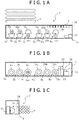
- a container-type compressed air energy storage (CAES) power generation device 2 according to a first embodiment of the present invention is shown in Fig. 1A to Fig. 1C and Fig. 2 .
- the container-type CAES power generation device 2 is configured so that CAES power generation units are housed in a container 4.
- the container-type CAES power generation device 2 is used, for example, for smoothing fluctuating power, cutting the peak demand, or storing electricity.
- the container-type CAES power generation device 2 of the first embodiment will be described with reference to Fig. 1A to Fig. 1C and Fig. 2 .
- the container-type CAES power generation device 2 is equipped with the CAES power generation units and the container 4.
- the CAES power generation units include three compressors 5a to 5c, tanks 8, three power generators 9a to 9c, and a control device 12.
- the compressors 5a to 5c, the power generators 9a to 9c, and the control device 12 are arranged inside the singe container 4, and the tanks 8 are arranged outside the container 4.
- the compressors 5a to 5c are connected via air supply pipes 14 (see Fig. 2 ) to the tanks 8, and the power generators 9a to 9c are connected via air supply pipes 14 to the tanks 8.
- the compressors 5a to 5c, the power generators 9a to 9c, and the control device 12 are arranged substantially in a row in the container 4 in the mentioned order from the left in Fig. 1A and Fig. 1B .
- the compressors 5a to 5c are provided with compressor bodies 6a to 6c and motors 16a to 16c that are mechanically connected to the compressor bodies 6a to 6c.
- the motors 16a to 16c are supplied with electric power from an electric power source (not shown) to be driven.
- the compressor bodies 6a to 6c absorb air surrounding the compressor bodies 6a to 6c to compress the air.
- the compressors 5a to 5c are connected via the air supply pipes 14 to the tanks 8, and the air compressed in the compressors 5a to 5c is supplied through the air supply pipes 14 to the tanks 8.
- Valves 18a to 18c are provided in the respective air supply pipes 14 located between the compressors 5a to 5c and the tanks 8.
- the valves 18a to 18c are, respectively, provided to the compressors 5a to 5c.
- the compressed air can be supplied selectively from any of the compressors 5a to 5c to the tanks 8.
- the number of compressors 5a to 5c to be used may be controlled by the valves 18a to 18c to regulate the volume of compressed air to be supplied to the tanks 8.
- the tanks 8 are configured to store the air compressed in the compressors 5a to 5c.
- the size and number of tanks 8 to be used are as shown in Fig. 1C . Twelve tanks 8 having the same size are provided in the first embodiment. Alternatively, the size and number of tanks 8 can be changed in accordance with, for example, the required electric power and the power-generating time and may be selected as necessary.
- the tanks 8 are connected to the power generators 9a to 9c via the air supply pipes 14, and the compressed air stored in the tanks 8 is supplied through the air supply pipes 14 to the power generators 9a to 9c.
- the power generators 9a to 9c are provided with expanders 20a to 20c that are mechanically connected to power generator bodies 10a to 10c.
- the expanders 20a to 20c are driven by the compressed air supplied from the tanks 8.
- the power generators 9a to 9c individually generate electric power.
- the power generators 9a to 9c connected to an external system (not shown) can supply the generated electric power to the external system.
- Valves 18d to 18f are provided in the respective air supply pipes 14 located between the tanks 8 and the power generators 9a to 9c.
- the valves 18d to 18f are, respectively, provided to the power generators 9a to 9c. Therefore, the compressed air from the tanks 8 can be selectively supplied to any of the power generators 9a to 9c. In this manner, the number of power generators 9a to 9c to be used may be controlled by the valves 18d to 18f to regulate the amount of electric power to be generated.
- the arrangement of the air supply pipes 14 inside and outside the container 4 will be described.
- the compressors 5a to 5c and the power generators 9a to 9c, both of which are housed in the container 4 are connected by the corresponding air supply pipes 14 to the tanks 8 arranged outside the container 4.
- a chain line 4A if the air supply pipes 14 are merged inside the container 4 to be subsequently extended outward from the container 4, the number of pipes outside the container 4 can be reduced; however, an extra space in the container 4 is reduced.
- the air supply pipes 14 are extended outward from the container 4 to be subsequently merged outside the container 4, the number of pipes outside the container 4 is increased; however, an extra space in the container 4 can be secured. As a result, the arrangement of the air supply pipes 14 may be changed according to pipe processing of the air supply pipes 14 or according to the necessity of an extra space in the container 4.
- the control device 12 includes a control board 22, an inverter 24, a reactor 26, and a converter 28; thereby, respective portions of the container-type CAES power generation device 2 are electrically connectable to one another.
- the converter 28 may be omitted depending on the output type.
- the control device 12 is electrically connected to the compressors 5a to 5c, the power generators 9a to 9c, and the valves 18a to 18f to control the operations thereof.
- the control device 12 is configured to control smoothing of fluctuating power.
- the valves 18a to 18c are opened to drive the compressors 5a to 5c; therefore, electric energy is stored as a form of the compressed air in the tanks 8. Further, when fluctuating power from the electric power source (not shown) is smaller than the predetermined value, the valves 18d to 18f are opened to drive the power generators 9a to 9c by the compressed air from the tanks 8; thereby, the power generators generate electric power.
- the predetermined value used here may be determined as a value of required electric power on the basis of data of the past electric power demand.
- control device 12 controls the operation of the compressors 5a to 5c, the power generators 9a to 9c, and the valves 18a to 18f, thereby smoothing fluctuating power.
- the control device 12 may be used not only for smoothing fluctuating power but also for cutting the peak demand as previously described.
- the container 4 of the first embodiment is a container with a length of 40 foot, which is used for transporting various kinds of general cargos; however, the type and size of container 4 is not limited to the 40-foot-length container. Alternatively, for example, a 20-foot-length container or another container, which is commonly and often used, may be applied as the container 4.
- the container-type CAES power generation device 2 is configured so that the CAES power generation units are housed in the container 4; thereby, the transportation and on-site construction of the CAES power generation device can be facilitated. Further, the tanks 8, each required capacity of which may vary depending on the power-generating time, are arranged outside the container 4; therefore, design changes of the CAES power generation units depending on whether the required power-generating time is short or long are not necessary, and the same package (the compressors 5a to 5c, the power generators 9a to 9c, and the control device 12) is usable, which is cost effective. Furthermore, since the CAES power generation device 2 is of the container type, plural CAES power generation devices may be arranged for use. Additional CAES power generation devices may be constructed to easily obtain high capacity. In addition, the CAES power generation device 2 can be placed in an outdoor location. Moreover, a side open container may be used as the container 4 to allow easy maintenance.
- both the compressors 5a to 5c and the power generators 9a to 9c are arranged in the container 4.
- the compressors 5a to 5c or the power generators 9a to 9c may be arranged in the container 4.
- the control device 12 may be arranged outside the container 4.
- the container-type CAES power generation device 2 according to a second embodiment of the present invention is shown in Fig. 3A to Fig. 3C and Fig. 4 .
- the container-type CAES power generation device 2 of the second embodiment is different from that of the first embodiment in that first heat exchangers 30a to 30c, second heat exchangers 32a to 32c, a first heat storage tank 33a, and a second heat storage tank 33b are provided, and other configurations of the container-type CAES power generation device 2 of the second embodiment are the same as those of the first embodiment in Fig. 1A to 1C and Fig. 2 . Accordingly, portions of the second embodiment, which are the same as those in the configurations shown in Fig. 1A to 1C and Fig. 2 are assigned with the same reference numbers and the description thereof will be omitted.
- the container-type CAES power generation device 2 of the second embodiment is equipped with the first heat exchangers 30a to 30c and the second heat exchangers 32a to 32c inside the container and with the heat storage tanks 33a, 33b outside the container 4.
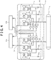
- the first heat exchangers 30a to 30c are connected via heat storage fluid supply pipes 34 (see Fig. 4 ) to the heat storage tanks 33a, 33b
- the second heat exchangers 32a to 32c are connected via heat storage fluid supply pipes 34 (see Fig. 4 ) to the heat storage tanks 33a, 33b.
- the first heat exchangers 30a to 30c (the compressors 5a to 5c), the second heat exchangers 32a to 32c (the power generators 9a to 9c), and the control device 12 are arranged substantially in a row in the container 4 in the mentioned order from the left in Fig. 3A and Fig. 3B .
- a heat storage fluid flows through the heat storage fluid supply pipes 34.
- Pumps 36a to 36f for allowing the heat storage fluid to flow are arranged in the respective heat storage fluid supply pipes 34.
- the heat storage fluid circulates with pressure from the pumps 36a to 36f to flow from the first heat exchangers 30a to 30c through the heat storage tank 33a to the second heat exchangers 32a to 32c and flow therefrom through the heat storage tank 33b back to the first heat exchangers 30a to 30c.
- the first heat exchangers 30a to 30c are, respectively, provided at the compressors 5a to 5c.
- Each first heat exchanger 30a to 30c is configured to transfer heat between the air flowing through corresponding one of the air supply pipes 14 located between the compressors 5a to 5c and the tanks 8 and the heat storage fluid flowing through corresponding one of the heat storage fluid supply pipes 34. Specifically, when the air is compressed by the compressors 5a to 5c and compression heat is therefore added to the air, heat is recovered from the compressed air and the heat storage fluid is heated by the recovered heat. The heated heat storage fluid is supplied through the heat storage fluid supply pipes 34 to the first heat storage tank 33a.
- the first heat storage tank 33a is configured to store the heat storage fluid that has been heated to high temperature in the first heat exchangers 30a to 30c.
- the first heat storage tank 33a may be formed by a heat insulating material so that the heat of the heat storage fluid stored at high temperature in the first heat storage tank 33a is not released to the outside.
- the heat storage fluid stored at high temperature in the first heat storage tank 33a is supplied through the corresponding heat storage fluid supply pipes 34 to the second heat exchangers 32a to 32c.
- the second heat exchangers 32a to 32c are, respectively, provided at the power generators 9a to 9c.
- Each second heat exchanger 32a to 32c is configured to transfer heat between the high-temperature heat storage fluid flowing through corresponding one of the heat storage fluid supply pipes 34 and the air flowing through corresponding one of the air supply pipes 14 located between the generators 9a to 9c and the tanks 8. Specifically, heat is recovered from the high-temperature heat storage fluid and the compressed air is therefore heated by the recovered heat. The compressed air that has been heated to high temperature is supplied through the corresponding air supply pipes 14 to the power generators 9a to 9c. The heat storage fluid that has been cooled by heat recovery in the second heat exchangers 32a to 32c is supplied through the heat storage fluid supply pipes 34 to the second heat storage tank 33b.
- the second heat storage tank 33b is configured to store the heat storage fluid that has been cooled by heat recovery in the second heat exchangers 32a to 32c.
- the second heat storage tank 33b may be formed by a heat insulating material so that the heat of the heat storage fluid stored in the second heat storage tank 33b is not released to the outside.
- the heat storage fluid stored in the second heat storage tank 33b is supplied through the heat storage fluid supply pipes 34 to the first heat exchangers 30a to 30c.
- the heat storage fluid is heated in the first heat exchangers 30a to 30c to be stored in the first heat storage tank 33a, thereafter being cooled by the second heat exchangers 32a to 32c to be stored in the second heat storage tank 33b. Then, the heat storage fluid is supplied back to the first heat exchangers 30a to 30c to be heated therein. Such process is repeated.
- the arrangement of the heat storage fluid supply pipes 34 inside and outside the container 4 is the same as the arrangement of the air supply pipes 14.
- the first heat exchangers 30a to 30c inside the container 4 are connected via the heat storage fluid supply pipes 34 to the heat storage tanks 33a, 33b outside the container 4, and the second heat exchangers 32a to 32c inside the container 4 are connected via the heat storage fluid supply pipes 34 to the heat storage tanks 33a, 33b outside the container 4.
- the number of pipes outside the container 4 can be reduced; however, an extra space in the container 4 is reduced.
- the heat storage fluid supply pipes 34 are extended outward from the container 4 to be subsequently merged outside the container 4, the number of pipes outside the container 4 is increased; however, an extra space in the container 4 can be easily secured.
- the arrangement of the heat storage fluid supply pipes 34 may be changed according to piping processing of the heat storage fluid supply pipes 34 or according to the necessity of an extra space in the container 4.
- the pumps 36a to 36f are arranged in the container 4; thereby, the transportation and on-site construction of the CAES power generation device is facilitated.
- the pumps 36a to 36f may be arranged in the container 4.
- the pumps 36a to 36f may be arranged outside the container 4 as shown in Fig. 5 ; thereby, an extra space in the container 4 can be easily secured.
- the second embodiment if a pump is provided in a location where the heat storage fluid supply pipes 34 are merged into one pipe line, the number of pumps can be reduced.
- the heat storage tanks 33a, 33b are arranged outside the container 4; therefore, design changes of the CAES power generation units depending on whether the required power-generating time is short or long are not necessary. Consequently, the same package is usable, which is cost effective.
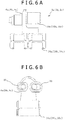
- FIG. 6A and Fig. 6B are front and side views, respectively, illustrating the layout of the first heat exchangers 30a to 30c and the compressors 5a to 5c.
- Each compressor 5a to 5c used in the second embodiment is a two-stage compressor including a low-pressure stage compression section 38 and a high-pressure stage compression section 40.
- Each first heat exchanger 30a to 30c functions as an intercooler for recovering heat from air compressed at the first stage by the low-pressure stage compression section 38 and cooling the compressed air and as an aftercooler for recovering compression heat from the air compressed at the second stage by the high-pressure stage compression section 40 and cooling the compressed air.
- each compressor 5a to 5c may be the two-stage compressor, but not limited thereto. Alternatively, each compressor 5a to 5c may be a three-stage compressor or a single-stage compressor.
- the layout of the second heat exchangers 32a to 32c is the same as the layout of the first heat exchangers 30a to 30c.
- the second heat exchangers 32a to 32c and the power generators 9a to 9c are arranged in the same layout as that of the first heat exchangers 30a to 30c and the compressors 5a to 5c.
- the second heat exchangers 32a to 32c are different from the first heat exchangers 30a to 30c in that each second heat exchanger functions as a heater relative to compressed air.
- the second heat exchanger functions as a preheater for heating air before the air is compressed at the first stage by the high-pressure stage compression section 40 and as an interheater for heating the air before the air is compressed at the second stage by the low-pressure stage compression section 38.
- the first heat exchangers 30a to 30c (the second heat exchangers 32a to 32c) are arranged at the lower side of the compressors 5a to 5c (the power generators 9a to 9c) so as to overlap the compressors 5a to 5c (the power generators 9a to 9c).
- the overlapping arrangement as just described, an installation area in the container 4 is not largely occupied and therefore a space can be effectively used.
- the compressors 5a to 5c are arranged adjacent to the first heat exchangers 30a to 30c so as to overlap the first heat exchangers 30a to 30c, or the power generators 9a to 9c are arranged adjacent to the second heat exchangers 32a to 32c so as to overlap the second heat exchangers 32a to 32c; therefore, the length of each of the air supply pipes 14 connecting these members can be reduced. Consequently, pressure loss or heat loss of the compressed air following through the air supply pipes 14 can be reduced.
- the compressors 5a to 5c or the power generators 9a to 9c or the like generate heat; therefore, the temperature inside the container 4 increases.
- electronics devices such as the control device 12 may be exposed to high temperatures.
- an ACAES power generation facility is used to perform heat recovery, the temperature inside the container 4 can be inhibited from increasing. Therefore, the electronics devices such as the control device 12 can be protected from being damaged by heat. More specifically, if a total-heat-recovery type ACAES power generation facility provided by the applicant of the present application in Japanese patent application No.
- the container-type CAES power generation device 2 according to a third embodiment of the present invention is shown in Fig. 7A to Fig. 7C and Fig. 8 .
- the container-type CAES power generation device 2 of the third embodiment is different from that of the second embodiment in the container 4 (a first container 4a and a second container 4b), and other configurations of the container-type CAES power generation device 2 of the third embodiment are the same as those of the second embodiment in Fig. 3A to 3C and Fig. 4 . Accordingly, portions of the third embodiment, which are the same as those in the configurations shown in Fig. 3A to 3C and Fig. 4 are assigned with the same reference numbers and the description thereof will be omitted.
- the container-type CAES power generation device 2 of the third embodiment is equipped with the first container 4a and the second container 4b.
- the first container 4a and the second container 4b are containers with a length of 20 foot, which are used for transporting various kinds of general cargos; however, the size of the first container 4a and the second container 4b is not limited to the 20-foot-length container. Alternatively, for example, 40-foot-length containers or other containers, which are commonly and often used, may be applied as the first container 4a and the second container 4b.
- Units related to the compression function are housed in the first container 4a.
- the units related to the compression function include the compressors 5a to 5c, the first heat exchangers 30a to 30c, and a control device 12a that is configured to control the compressors and the first heat exchangers.
- Units related to the power generation function are housed in the second container 4b.
- the units related to the power generation function include the power generators 9a to 9c, the second heat exchangers 32a to 32c, and a control device 12b that is configured to control the power generators and the second heat exchangers.
- the arrangement of the air supply pipes 14 and the heat storage fluid supply pipes 34 inside the first container 4a and the second container 4b or outside the first container 4a and the second container 4b is the same as that in the second embodiment.
- the air supply pipes 14 may be merged inside the first container 4a and the second container 4b (see chain lines 4A in Fig. 8 ) or outside the first container 4a and the second container 4b (see two-dot chain lines 4B in Fig. 8 ).
- the heat storage fluid supply pipes 34 may be merged inside or outside the first container 4a and the second container 4b.
- the pumps 36a to 36c are arranged inside the first container 4a
- the pumps 36d to 36f are arranged inside the second container 4b.
- the pumps 36a to 36c may be arranged outside the first container 4a
- the pumps 36d to 36f may be arranged outside the second container 4b in the same way as in the second embodiment (see Fig. 4 and Fig. 5 ).
- the container-type CAES power generation device 2 of the third embodiment is provided with the first container 4a having the compression function and the second container 4b having the power generation function; thereby, each container 4a, 4b can be downsized.
- Such downsizing allows the container-type CAES power generation device to be more easily transported, and the design flexibility of the layout for arranging each container 4a, 4b can be expanded.
- the container-type CAES power generation device 2 according to a fourth embodiment of the present invention is shown in Fig. 9 .
- the container-type CAES power generation device 2 of the fourth embodiment is different from that of the second embodiment in that a heat storage container 41 is provided, and other configurations of the container-type CAES power generation device 2 of the fourth embodiment are the same as those of the second embodiment in Fig. 5 . Accordingly, portions of the fourth embodiment, which are the same as the configurations shown in Fig. 5 are assigned with the same reference numbers and the description thereof will be omitted.
- the container-type CAES power generation device 2 of the fourth embodiment is equipped with the heat storage container 41.
- the heat storage container 41 houses the first heat storage tank 33a and the second heat storage tank 33b.
- the size and configuration of the heat storage container 41 may be changed in accordance with the arrangement of the heat storage fluid supply pipes 34.
- the heat storage fluid supply pipes 34 may be merged inside the heat storage container 41 to be subsequently extended outward from the heat storage container 41.
- the heat storage fluid supply pipes 34 may be extended outward from the heat storage container 41 to be subsequently merged outside the heat storage container 41.
- the size and configuration of the heat storage container 41 may be changed according to piping processing of the heat storage fluid supply pipes 34 or according to the necessity of an extra space in the heat storage container 41.
- the heat storage container 41 is an insulated container (also referred to as a thermal container) internally provided with a heat insulating material.
- the heat storage container 41 internally includes a partition 42 so as to separately house the first heat storage tank 33a and the second heat storage tank 33b.
- the temperature of the heat storage fluid to be stored in the first heat storage tank 33a is different from the temperature of the heat storage fluid to be stored in the second heat storage tank 33b.
- the partition 42 is provided in the heat storage container; thereby, the internal space can be separated and heat loss due to heat radiation can be prevented.
- the partition 42 is also formed of a heat insulating material, thereby further preventing heat loss.
- the pumps 36a to 36f are arranged in the heat storage container 41; thereby, the transportation and on-site construction of the CAES power generation device is facilitated.
- the pumps 36a to 36f may not necessarily be arranged in the heat storage container 41.
- the pumps 36a to 36f may be arranged in the container 4 as in Fig. 4 or may be arranged outside the container 4 or the container 41. In order to enable an easier construction, the pumps 36a to 36f may be arranged in either the container 4 or the container 41.
- the container-type CAES power generation device 2 according to a fifth embodiment of the present invention is shown in Fig. 10 .
- the container-type CAES power generation device 2 of the fifth embodiment is different from the fourth embodiment in that the heat storage container 41 (a third container 41a and a fourth container 41b) is provided, and other configurations of the container-type CAES power generation device 2 of the fifth embodiment are the same as the configurations of the fourth embodiment in Fig. 9 . Accordingly, portions of the fifth embodiment, which are the same as the configurations shown in Fig. 9 are assigned with the same reference numbers and the description thereof will be omitted.
- the container-type CAES power generation device 2 of the fifth embodiment is equipped with the heat storage container 41.
- the heat storage container 41 includes the third container 41a and the fourth container 41b.
- the third container 41a houses the first heat storage tank 33a.
- the fourth container 41b houses the second heat storage tank 33b.
- the arrangement of the heat storage fluid supply pipes 34 inside the third container 41a and the fourth container 41b or outside the third container 41a and the fourth container 41b is the same as that in the fourth embodiment.
- the heat storage fluid supply pipes 34 may be merged inside the third container 41a and the fourth container 41b (see two-dot chain lines 41B in Fig. 10 ) or outside the third container 41a and the fourth container 41b (see chain lines 41A in Fig. 10 ).
- the pumps 36a to 36f are arranged inside the heat storage container 41 in Fig. 10 .
- the pumps 36a to 36f may be arranged outside the heat storage container 41 in the same way as in the second embodiment.
- Each of the third container 41a and the fourth container 41b is an insulated container internally provided with a heat insulating material.
- the temperature of the heat storage fluid to be stored in the first heat storage tank 33a is different from the temperature of the heat storage fluid to be stored in the second heat storage tank 33b. Accordingly, a storage space is separated as the third container 41a and the fourth container 41b are provided; thereby, heat loss due to heat radiation can be prevented.
- the number of compressors 5a to 5c is equal to the number of power generators 9a to 9c.
- the number or the capacity of compressors 5a to 5c may not necessarily be equal to the number or the capacity of power generators 9a to 9c.
- the number or the capacity of the compressors 5a to 5c can be smaller than the number or the capacity of the power generators 9a to 9c and vice versa.
- the first container 4a having the compression function and the second container 4b having the power generation function may be used in a state where the number of first containers 4a and the number of second containers 4b are altered.
- each tank 8 is not limited to such configuration.
- the tank may be buried underground, or a tunnel or an underground space may be used as the tank.
Landscapes
- Engineering & Computer Science (AREA)
- Mechanical Engineering (AREA)
- General Engineering & Computer Science (AREA)
- Chemical & Material Sciences (AREA)
- Combustion & Propulsion (AREA)
- Filling Or Discharging Of Gas Storage Vessels (AREA)
- Heat-Exchange Devices With Radiators And Conduit Assemblies (AREA)
- Engine Equipment That Uses Special Cycles (AREA)
- Compressors, Vaccum Pumps And Other Relevant Systems (AREA)
- Applications Or Details Of Rotary Compressors (AREA)
Abstract
Description
- The present invention relates to a compressed air energy storage power generation device.
- A compressed air energy storage (CAES) power generation device stores electric energy as a form of compressed air during off-peak hours of a power generation plant and operates a power generator by using the stored compressed air during times of high power demand, thereby generating electric energy.
- A typical CAES power generation device releases compression heat during storage of the compressed air, resulting in energy loss. A power generation device configured to prevent such energy loss to improve system efficiency is an adiabatic compressed air energy storage (ACAES) power generation device. The ACAES power generation device recovers and stores compressed air to prevent compression heat from being released during storage of the compressed air, and the stored heat is returned to the compressed air for driving an expander. Thus, system efficiency is improved.
- The ACAES power generation device configured as above is disclosed, for example in,
Patent Document 1. - An ACAES power generation device configured to store compression heat in a thermal energy storage (TES) system is disclosed in
Patent Document 1. - A compressor, a power generator, a tank, or the like of a known CAES power generation device including the power generation device disclosed in
Patent Document 1 are all assembled on site; therefore, the transportation of the CAES power generation device is complicated and the construction thereof requires time and cost. - Patent Document 1 :
JP 2013-512410 A - An object of the present invention is to provide a CAES power generation device that facilitates the transportation and on-site construction thereof.
- The present invention provides a container-type compressed air energy storage power generation device including: a compressor for compressing air; a tank for storing the air compressed by the compressor; a power generator to be operated by the air supplied from the tank; a control device for controlling operation of the compressor and the power generator; and a container, wherein at least one of the compressor and the power generator is housed in the container, wherein the tank is arranged outside the container. Alternatively, the container-type compressed air energy storage power generation device may be configured so that both the compressor and the power generator are housed in the container.
- According to the container-type compressed air energy storage power generation device, units required for the CAES power generation device are housed in the container; thereby, the transportation and on-site construction of the CAES power generation device can be facilitated. Further, the compressed air storage tank, the required capacity of which may vary depending on the power-generating time, is separately provided outside the container. Therefore, design changes of portions of the power generation device depending on whether the required power-generating time is short or long are not necessary, and the same package is usable, which is cost effective.
- The container of the container-type compressed air energy storage power generation device may include a first container housing the compressor and a second container housing the power generator. Further, a first heat exchanger may be housed in the first container and a second heat exchanger may be housed in the second container.
- According to the container-type compressed air energy storage power generation device, the container is divided into a portion having the compression function and a portion having the power generation function,; thereby, the container can be downsized. Such downsizing allows the power generation device to be more easily transported, and the design flexibility of the layout for arranging the container can be expanded.
- The container-type compressed air energy storage power generation device may further include: a first heat exchanger for transferring heat between the air, compressed and heated in the compressor to be supplied into the tank, and a heat storage fluid and for heating the heat storage fluid; a second heat exchanger for transferring heat between the air, supplied from the tank to the power generator, and the heat storage fluid and heating the air; and a heat storage section for storing the heat storage fluid, the heat storage section being fluidly connected to the first heat exchanger and the second heat exchanger, wherein the first heat exchanger may be housed in the container housing the compressor and the second heat exchanger may be housed in the container housing the power generator, and wherein the heat storage section may be arranged outside the container housing the compressor and outside the container housing the power generator.
- According to the container-type compressed air energy storage power generation device, units required for an adiabatic compressed air energy storage (ACAES) power generation device are housed in the container; thereby, the transportation and on-site construction of the ACAES power generation device can be facilitated. Further, the heat storage section, the required capacity of which may vary depending on the power-generating time, is separately provided outside the container. Therefore, design changes of portions of the power generation device depending on whether the required power-generating time is short or long are not necessary, and the same package is usable, which is cost effective.
- The heat storage section of the container-type compressed air energy storage power generation device may include: a first heat storage tank for storing the heat storage fluid heated to high temperature in the first heat exchanger, the first heat storage tank being fluidly connected to the second heat exchanger so that the heated heat storage fluid is supplied to the second heat exchanger; and a second heat storage tank for storing the heat storage fluid cooled by heat recovery in the second heat exchanger, the second heat storage tank being fluidly connected to the first heat exchanger so that the cooled heat storage fluid is supplied to the first heat exchanger.
- According to the container-type compressed air energy storage power generation device, two heat storage tanks of the first heat storage tank and the second heat storage tank are provided; thereby, the heat storage fluid can be stored at different temperatures. As a result, the heat exchanger effectiveness in the first heat exchanger and the second heat exchanger can be increased.
- The container-type compressed air energy storage power generation device may further include a heat storage container housing the heat storage section.
- The container-type compressed air energy storage power generation device further includes the heat storage container housing the heat storage section; therefore, heat loss due to heat radiation can be prevent, and the transportation and on-site construction of the container-type compressed air energy storage power generation device can be facilitated.
- The container-type compressed air energy storage power generation device may further include a heat storage container housing the heat storage section, the heat storage container being internally provided with a partition to separately house the first heat storage tank and the second heat storage tank.
- According to the container-type compressed air energy storage power generation device, the heat storage container is internally provided with the partition; thereby, the first heat storage tank and the second heat storage tank can be separately housed. Therefore, heat loss due to heat radiation can be prevented.
- The container-type compressed air energy storage power generation device may further include a heat storage container housing the heat storage section, the heat storage container including a third container storing the first heat storage tank and a fourth container storing the second heat storage tank.
- According to the container-type compressed air energy storage power generation device, the heat storage container includes the third container and the fourth container; thereby, the first heat storage tank and the second heat storage tank can be separately housed and heat loss due to heat radiation can be prevented.
- The heat storage container, housing the heat storage section, of the container-type compressed air energy storage power generation device may be an insulated container internally provided with a heat insulating material.
- According to the container-type compressed air energy storage power generation device, the heat storage container is internally provided with the heat insulating material; thereby, heat loss due to heat radiation can be prevented.
- The container-type compressed air energy storage power generation device may be configured such that the first heat exchanger is arranged at the lower side of the compressor so as to overlap the compressor and such that the second heat exchanger is arranged at the lower side of the power generator so as to overlap the power generator.
- According to the container-type compressed air energy storage power generation device, a limited space in the container can be effectively used and therefore the size of the container may be prevented from being increased. In addition, the first and second heat exchangers are arranged so as that the compressor and the power generator overlap the first and second heat exchangers, respectively; thereby, pneumatic piping (air supply piping) can be reduced, and heat loss due to heat radiation can be prevented.
- According to the present invention, at least one of the compressor and the power generator of the CAES power generation device is housed in the container; thereby, the transportation and on-site construction of the CAES power generation device can be facilitated.
-
- [
Fig. 1A] Fig. 1A is a schematic plan view of a container-type CAES power generation device according to a first embodiment of the present invention. - [
Fig. 1B] Fig. 1B is a schematic front view of the container-type CAES power generation device according to the first embodiment of the present invention. - [
Fig. 1C] Fig. 1C is a schematic side view of the container-type CAES power generation device according to the first embodiment of the present invention. - [
Fig. 2] Fig. 2 is a schematic configuration diagram illustrating connection configurations of respective portions inFig. 1A to Fig. 1C . - [
Fig. 3A] Fig. 3A is a schematic plan view of the container-type CAES power generation device according to a second embodiment of the present invention. - [
Fig. 3B] Fig. 3B is a schematic front view of the container-type CAES power generation device according to the second embodiment of the present invention. - [
Fig. 3C] Fig. 3C is a schematic side view of the container-type CAES power generation device according to the second embodiment of the present invention. - [
Fig. 4] Fig. 4 is a schematic configuration diagram illustrating connection configurations of respective portions inFig. 3A to Fig. 3C . - [
Fig. 5] Fig. 5 is a schematic configuration diagram illustrating a case where a pump for driving a heat storage fluid is arranged outside a container. - [
Fig. 6A] Fig. 6A is a side view of the layout of a compressor and a first heat exchanger. - [
Fig. 6B] Fig. 6B is a front view of the layout of the compressor and the first heat exchanger. - [
Fig. 7A] Fig. 7A is a plan view of the container-type CAES power generation device according to a third embodiment of the present invention. - [
Fig. 7B] Fig. 7B is a front view of the container-type CAES power generation device according to the third embodiment of the present invention. - [
Fig. 7C] Fig. 7C is a side view of the container-type CAES power generation device according to the third embodiment of the present invention. - [
Fig. 8] Fig. 8 is a schematic configuration diagram illustrating connection configurations of respective portions inFig. 7A to Fig. 7C . - [
Fig. 9] Fig. 9 is a schematic configuration diagram illustrating connection configurations of respective portions of the container-type CAES power generation device according to a fourth embodiment of the present invention. - [
Fig. 10] Fig. 10 is a schematic configuration diagram illustrating connection configurations of respective portions of the container-type CAES power generation device according to a fifth embodiment of the present invention. - Hereinafter, embodiments of the present invention will be described with reference to the accompanying drawings.
- A container-type compressed air energy storage (CAES)
power generation device 2 according to a first embodiment of the present invention is shown inFig. 1A to Fig. 1C andFig. 2 . The container-type CAESpower generation device 2 is configured so that CAES power generation units are housed in acontainer 4. The container-type CAESpower generation device 2 is used, for example, for smoothing fluctuating power, cutting the peak demand, or storing electricity. - The container-type CAES
power generation device 2 of the first embodiment will be described with reference toFig. 1A to Fig. 1C andFig. 2 . - The container-type CAES
power generation device 2 is equipped with the CAES power generation units and thecontainer 4. The CAES power generation units include threecompressors 5a to 5c,tanks 8, threepower generators 9a to 9c, and acontrol device 12. In the container-type CAESpower generation device 2 of the first embodiment, thecompressors 5a to 5c, thepower generators 9a to 9c, and thecontrol device 12 are arranged inside thesinge container 4, and thetanks 8 are arranged outside thecontainer 4. Thecompressors 5a to 5c are connected via air supply pipes 14 (seeFig. 2 ) to thetanks 8, and thepower generators 9a to 9c are connected viaair supply pipes 14 to thetanks 8. In the first embodiment, thecompressors 5a to 5c, thepower generators 9a to 9c, and thecontrol device 12 are arranged substantially in a row in thecontainer 4 in the mentioned order from the left inFig. 1A and Fig. 1B . - The
compressors 5a to 5c are provided withcompressor bodies 6a to 6c andmotors 16a to 16c that are mechanically connected to thecompressor bodies 6a to 6c. Themotors 16a to 16c are supplied with electric power from an electric power source (not shown) to be driven. When themotors 16a to 16c are driven, thecompressor bodies 6a to 6c absorb air surrounding thecompressor bodies 6a to 6c to compress the air. Thecompressors 5a to 5c are connected via theair supply pipes 14 to thetanks 8, and the air compressed in thecompressors 5a to 5c is supplied through theair supply pipes 14 to thetanks 8. -
Valves 18a to 18c are provided in the respectiveair supply pipes 14 located between thecompressors 5a to 5c and thetanks 8. Thevalves 18a to 18c are, respectively, provided to thecompressors 5a to 5c. The compressed air can be supplied selectively from any of thecompressors 5a to 5c to thetanks 8. In addition, the number ofcompressors 5a to 5c to be used may be controlled by thevalves 18a to 18c to regulate the volume of compressed air to be supplied to thetanks 8. - The
tanks 8 are configured to store the air compressed in thecompressors 5a to 5c. The size and number oftanks 8 to be used are as shown inFig. 1C . Twelvetanks 8 having the same size are provided in the first embodiment. Alternatively, the size and number oftanks 8 can be changed in accordance with, for example, the required electric power and the power-generating time and may be selected as necessary. Thetanks 8 are connected to thepower generators 9a to 9c via theair supply pipes 14, and the compressed air stored in thetanks 8 is supplied through theair supply pipes 14 to thepower generators 9a to 9c. - The
power generators 9a to 9c are provided withexpanders 20a to 20c that are mechanically connected topower generator bodies 10a to 10c. Theexpanders 20a to 20c are driven by the compressed air supplied from thetanks 8. When theexpanders 20a to 20c are driven, thepower generators 9a to 9c individually generate electric power. Thepower generators 9a to 9c connected to an external system (not shown) can supply the generated electric power to the external system. -
Valves 18d to 18f are provided in the respectiveair supply pipes 14 located between thetanks 8 and thepower generators 9a to 9c. In the first embodiment, thevalves 18d to 18f are, respectively, provided to thepower generators 9a to 9c. Therefore, the compressed air from thetanks 8 can be selectively supplied to any of thepower generators 9a to 9c. In this manner, the number ofpower generators 9a to 9c to be used may be controlled by thevalves 18d to 18f to regulate the amount of electric power to be generated. - The arrangement of the
air supply pipes 14 inside and outside thecontainer 4 will be described. Thecompressors 5a to 5c and thepower generators 9a to 9c, both of which are housed in thecontainer 4 are connected by the correspondingair supply pipes 14 to thetanks 8 arranged outside thecontainer 4. For example, as indicated by achain line 4A, if theair supply pipes 14 are merged inside thecontainer 4 to be subsequently extended outward from thecontainer 4, the number of pipes outside thecontainer 4 can be reduced; however, an extra space in thecontainer 4 is reduced. On the other hand, as indicated by a two-dot chain line 4B, if theair supply pipes 14 are extended outward from thecontainer 4 to be subsequently merged outside thecontainer 4, the number of pipes outside thecontainer 4 is increased; however, an extra space in thecontainer 4 can be secured. As a result, the arrangement of theair supply pipes 14 may be changed according to pipe processing of theair supply pipes 14 or according to the necessity of an extra space in thecontainer 4. - The
control device 12 includes acontrol board 22, aninverter 24, areactor 26, and aconverter 28; thereby, respective portions of the container-type CAESpower generation device 2 are electrically connectable to one another. Theconverter 28 may be omitted depending on the output type. Thecontrol device 12 is electrically connected to thecompressors 5a to 5c, thepower generators 9a to 9c, and thevalves 18a to 18f to control the operations thereof. For example, thecontrol device 12 is configured to control smoothing of fluctuating power. In the power smoothing control, when fluctuating power from the electric power source (not shown) is greater than a predetermined value, thevalves 18a to 18c are opened to drive thecompressors 5a to 5c; therefore, electric energy is stored as a form of the compressed air in thetanks 8. Further, when fluctuating power from the electric power source (not shown) is smaller than the predetermined value, thevalves 18d to 18f are opened to drive thepower generators 9a to 9c by the compressed air from thetanks 8; thereby, the power generators generate electric power. The predetermined value used here may be determined as a value of required electric power on the basis of data of the past electric power demand. As just described, thecontrol device 12 controls the operation of thecompressors 5a to 5c, thepower generators 9a to 9c, and thevalves 18a to 18f, thereby smoothing fluctuating power. Thecontrol device 12 may be used not only for smoothing fluctuating power but also for cutting the peak demand as previously described. - The
container 4 of the first embodiment is a container with a length of 40 foot, which is used for transporting various kinds of general cargos; however, the type and size ofcontainer 4 is not limited to the 40-foot-length container. Alternatively, for example, a 20-foot-length container or another container, which is commonly and often used, may be applied as thecontainer 4. - The container-type CAES
power generation device 2 is configured so that the CAES power generation units are housed in thecontainer 4; thereby, the transportation and on-site construction of the CAES power generation device can be facilitated. Further, thetanks 8, each required capacity of which may vary depending on the power-generating time, are arranged outside thecontainer 4; therefore, design changes of the CAES power generation units depending on whether the required power-generating time is short or long are not necessary, and the same package (thecompressors 5a to 5c, thepower generators 9a to 9c, and the control device 12) is usable, which is cost effective. Furthermore, since the CAESpower generation device 2 is of the container type, plural CAES power generation devices may be arranged for use. Additional CAES power generation devices may be constructed to easily obtain high capacity. In addition, the CAESpower generation device 2 can be placed in an outdoor location. Moreover, a side open container may be used as thecontainer 4 to allow easy maintenance. - In the first embodiment, both the
compressors 5a to 5c and thepower generators 9a to 9c are arranged in thecontainer 4. Alternatively, only either thecompressors 5a to 5c or thepower generators 9a to 9c may be arranged in thecontainer 4. Thecontrol device 12 may be arranged outside thecontainer 4. - The container-type CAES
power generation device 2 according to a second embodiment of the present invention is shown inFig. 3A to Fig. 3C andFig. 4 . The container-type CAESpower generation device 2 of the second embodiment is different from that of the first embodiment in thatfirst heat exchangers 30a to 30c,second heat exchangers 32a to 32c, a firstheat storage tank 33a, and a secondheat storage tank 33b are provided, and other configurations of the container-type CAESpower generation device 2 of the second embodiment are the same as those of the first embodiment inFig. 1A to 1C andFig. 2 . Accordingly, portions of the second embodiment, which are the same as those in the configurations shown inFig. 1A to 1C andFig. 2 are assigned with the same reference numbers and the description thereof will be omitted. - With reference to
Fig. 3A to 3C andFig. 4 , the container-type CAESpower generation device 2 of the second embodiment is equipped with thefirst heat exchangers 30a to 30c and thesecond heat exchangers 32a to 32c inside the container and with theheat storage tanks container 4. Thefirst heat exchangers 30a to 30c are connected via heat storage fluid supply pipes 34 (seeFig. 4 ) to theheat storage tanks second heat exchangers 32a to 32c are connected via heat storage fluid supply pipes 34 (seeFig. 4 ) to theheat storage tanks first heat exchangers 30a to 30c (thecompressors 5a to 5c), thesecond heat exchangers 32a to 32c (thepower generators 9a to 9c), and thecontrol device 12 are arranged substantially in a row in thecontainer 4 in the mentioned order from the left inFig. 3A and Fig. 3B . - A heat storage fluid flows through the heat storage
fluid supply pipes 34.Pumps 36a to 36f for allowing the heat storage fluid to flow are arranged in the respective heat storagefluid supply pipes 34. The heat storage fluid circulates with pressure from thepumps 36a to 36f to flow from thefirst heat exchangers 30a to 30c through theheat storage tank 33a to thesecond heat exchangers 32a to 32c and flow therefrom through theheat storage tank 33b back to thefirst heat exchangers 30a to 30c. - The
first heat exchangers 30a to 30c are, respectively, provided at thecompressors 5a to 5c. Eachfirst heat exchanger 30a to 30c is configured to transfer heat between the air flowing through corresponding one of theair supply pipes 14 located between thecompressors 5a to 5c and thetanks 8 and the heat storage fluid flowing through corresponding one of the heat storagefluid supply pipes 34. Specifically, when the air is compressed by thecompressors 5a to 5c and compression heat is therefore added to the air, heat is recovered from the compressed air and the heat storage fluid is heated by the recovered heat. The heated heat storage fluid is supplied through the heat storagefluid supply pipes 34 to the firstheat storage tank 33a. - The first
heat storage tank 33a is configured to store the heat storage fluid that has been heated to high temperature in thefirst heat exchangers 30a to 30c. The firstheat storage tank 33a may be formed by a heat insulating material so that the heat of the heat storage fluid stored at high temperature in the firstheat storage tank 33a is not released to the outside. The heat storage fluid stored at high temperature in the firstheat storage tank 33a is supplied through the corresponding heat storagefluid supply pipes 34 to thesecond heat exchangers 32a to 32c. - The
second heat exchangers 32a to 32c are, respectively, provided at thepower generators 9a to 9c. Eachsecond heat exchanger 32a to 32c is configured to transfer heat between the high-temperature heat storage fluid flowing through corresponding one of the heat storagefluid supply pipes 34 and the air flowing through corresponding one of theair supply pipes 14 located between thegenerators 9a to 9c and thetanks 8. Specifically, heat is recovered from the high-temperature heat storage fluid and the compressed air is therefore heated by the recovered heat. The compressed air that has been heated to high temperature is supplied through the correspondingair supply pipes 14 to thepower generators 9a to 9c. The heat storage fluid that has been cooled by heat recovery in thesecond heat exchangers 32a to 32c is supplied through the heat storagefluid supply pipes 34 to the secondheat storage tank 33b. - The second
heat storage tank 33b is configured to store the heat storage fluid that has been cooled by heat recovery in thesecond heat exchangers 32a to 32c. The secondheat storage tank 33b may be formed by a heat insulating material so that the heat of the heat storage fluid stored in the secondheat storage tank 33b is not released to the outside. The heat storage fluid stored in the secondheat storage tank 33b is supplied through the heat storagefluid supply pipes 34 to thefirst heat exchangers 30a to 30c. - As described above, the heat storage fluid is heated in the
first heat exchangers 30a to 30c to be stored in the firstheat storage tank 33a, thereafter being cooled by thesecond heat exchangers 32a to 32c to be stored in the secondheat storage tank 33b. Then, the heat storage fluid is supplied back to thefirst heat exchangers 30a to 30c to be heated therein. Such process is repeated. - The arrangement of the heat storage
fluid supply pipes 34 inside and outside thecontainer 4 is the same as the arrangement of theair supply pipes 14. Thefirst heat exchangers 30a to 30c inside thecontainer 4 are connected via the heat storagefluid supply pipes 34 to theheat storage tanks container 4, and thesecond heat exchangers 32a to 32c inside thecontainer 4 are connected via the heat storagefluid supply pipes 34 to theheat storage tanks container 4. For example, as indicated by achain line 4A, if the heat storagefluid supply pipes 34 are merged inside thecontainer 4 to be subsequently extended outward from thecontainer 4, the number of pipes outside thecontainer 4 can be reduced; however, an extra space in thecontainer 4 is reduced. On the other hand, as indicated by a two-dot chain line 4B, if the heat storagefluid supply pipes 34 are extended outward from thecontainer 4 to be subsequently merged outside thecontainer 4, the number of pipes outside thecontainer 4 is increased; however, an extra space in thecontainer 4 can be easily secured. As a result, the arrangement of the heat storagefluid supply pipes 34 may be changed according to piping processing of the heat storagefluid supply pipes 34 or according to the necessity of an extra space in thecontainer 4. - In the second embodiment, as shown in
Fig. 4 , thepumps 36a to 36f are arranged in thecontainer 4; thereby, the transportation and on-site construction of the CAES power generation device is facilitated. However, it may not be necessary for thepumps 36a to 36f to be arranged in thecontainer 4. Alternatively, thepumps 36a to 36f may be arranged outside thecontainer 4 as shown inFig. 5 ; thereby, an extra space in thecontainer 4 can be easily secured. Further, in the second embodiment, if a pump is provided in a location where the heat storagefluid supply pipes 34 are merged into one pipe line, the number of pumps can be reduced. - In the container-type CAES
power generation device 2 of the second embodiment, theheat storage tanks container 4; therefore, design changes of the CAES power generation units depending on whether the required power-generating time is short or long are not necessary. Consequently, the same package is usable, which is cost effective. - The layout of the
first heat exchangers 30a to 30c will be described.Fig. 6A and Fig. 6B are front and side views, respectively, illustrating the layout of thefirst heat exchangers 30a to 30c and thecompressors 5a to 5c. Eachcompressor 5a to 5c used in the second embodiment is a two-stage compressor including a low-pressurestage compression section 38 and a high-pressurestage compression section 40. Eachfirst heat exchanger 30a to 30c functions as an intercooler for recovering heat from air compressed at the first stage by the low-pressurestage compression section 38 and cooling the compressed air and as an aftercooler for recovering compression heat from the air compressed at the second stage by the high-pressurestage compression section 40 and cooling the compressed air. Note that eachcompressor 5a to 5c may be the two-stage compressor, but not limited thereto. Alternatively, eachcompressor 5a to 5c may be a three-stage compressor or a single-stage compressor. - The layout of the
second heat exchangers 32a to 32c is the same as the layout of thefirst heat exchangers 30a to 30c. In other words, inFig. 6A and Fig. 6B , if thefirst heat exchangers 30a to 30c are replaced with thesecond heat exchangers 32a to 32c, and thecompressors 5a to 5c are replaced with thepower generators 9a to 9c, thesecond heat exchangers 32a to 32c and thepower generators 9a to 9c are arranged in the same layout as that of thefirst heat exchangers 30a to 30c and thecompressors 5a to 5c. Note that thesecond heat exchangers 32a to 32c are different from thefirst heat exchangers 30a to 30c in that each second heat exchanger functions as a heater relative to compressed air. In other words, the second heat exchanger functions as a preheater for heating air before the air is compressed at the first stage by the high-pressurestage compression section 40 and as an interheater for heating the air before the air is compressed at the second stage by the low-pressurestage compression section 38. - As shown in
Fig. 6A and Fig. 6B , thefirst heat exchangers 30a to 30c (thesecond heat exchangers 32a to 32c) are arranged at the lower side of thecompressors 5a to 5c (thepower generators 9a to 9c) so as to overlap thecompressors 5a to 5c (thepower generators 9a to 9c). With the overlapping arrangement as just described, an installation area in thecontainer 4 is not largely occupied and therefore a space can be effectively used. In addition, thecompressors 5a to 5c are arranged adjacent to thefirst heat exchangers 30a to 30c so as to overlap thefirst heat exchangers 30a to 30c, or thepower generators 9a to 9c are arranged adjacent to thesecond heat exchangers 32a to 32c so as to overlap thesecond heat exchangers 32a to 32c; therefore, the length of each of theair supply pipes 14 connecting these members can be reduced. Consequently, pressure loss or heat loss of the compressed air following through theair supply pipes 14 can be reduced. - In a case where the CAES power generation units are housed in the
container 4, thecompressors 5a to 5c (or thepower generators 9a to 9c) or the like generate heat; therefore, the temperature inside thecontainer 4 increases. As a result, electronics devices such as thecontrol device 12 may be exposed to high temperatures. However, if an ACAES power generation facility is used to perform heat recovery, the temperature inside thecontainer 4 can be inhibited from increasing. Therefore, the electronics devices such as thecontrol device 12 can be protected from being damaged by heat. More specifically, if a total-heat-recovery type ACAES power generation facility provided by the applicant of the present application inJapanese patent application No. 2014-172836 container 4 scarcely occurs; therefore, a ventilation fan or an air-conditioning apparatus is not required. Consequently, it may only have to provide a ventilation hole for allowing a free flow of air. - The container-type CAES
power generation device 2 according to a third embodiment of the present invention is shown inFig. 7A to Fig. 7C andFig. 8 . The container-type CAESpower generation device 2 of the third embodiment is different from that of the second embodiment in the container 4 (afirst container 4a and asecond container 4b), and other configurations of the container-type CAESpower generation device 2 of the third embodiment are the same as those of the second embodiment inFig. 3A to 3C andFig. 4 . Accordingly, portions of the third embodiment, which are the same as those in the configurations shown inFig. 3A to 3C andFig. 4 are assigned with the same reference numbers and the description thereof will be omitted. - With reference to
Fig. 7A to 7C andFig. 8 , the container-type CAESpower generation device 2 of the third embodiment is equipped with thefirst container 4a and thesecond container 4b. Thefirst container 4a and thesecond container 4b are containers with a length of 20 foot, which are used for transporting various kinds of general cargos; however, the size of thefirst container 4a and thesecond container 4b is not limited to the 20-foot-length container. Alternatively, for example, 40-foot-length containers or other containers, which are commonly and often used, may be applied as thefirst container 4a and thesecond container 4b. - Units related to the compression function are housed in the
first container 4a. The units related to the compression function include thecompressors 5a to 5c, thefirst heat exchangers 30a to 30c, and acontrol device 12a that is configured to control the compressors and the first heat exchangers. - Units related to the power generation function are housed in the
second container 4b. The units related to the power generation function include thepower generators 9a to 9c, thesecond heat exchangers 32a to 32c, and acontrol device 12b that is configured to control the power generators and the second heat exchangers. - The arrangement of the
air supply pipes 14 and the heat storagefluid supply pipes 34 inside thefirst container 4a and thesecond container 4b or outside thefirst container 4a and thesecond container 4b is the same as that in the second embodiment. In other words, theair supply pipes 14 may be merged inside thefirst container 4a and thesecond container 4b (seechain lines 4A inFig. 8 ) or outside thefirst container 4a and thesecond container 4b (see two-dot chain lines 4B inFig. 8 ). Likewise, the heat storagefluid supply pipes 34 may be merged inside or outside thefirst container 4a and thesecond container 4b. InFig. 8 , thepumps 36a to 36c are arranged inside thefirst container 4a, and thepumps 36d to 36f are arranged inside thesecond container 4b. Alternatively, thepumps 36a to 36c may be arranged outside thefirst container 4a, and thepumps 36d to 36f may be arranged outside thesecond container 4b in the same way as in the second embodiment (seeFig. 4 andFig. 5 ). - The container-type CAES
power generation device 2 of the third embodiment is provided with thefirst container 4a having the compression function and thesecond container 4b having the power generation function; thereby, eachcontainer container - The container-type CAES
power generation device 2 according to a fourth embodiment of the present invention is shown inFig. 9 . The container-type CAESpower generation device 2 of the fourth embodiment is different from that of the second embodiment in that aheat storage container 41 is provided, and other configurations of the container-type CAESpower generation device 2 of the fourth embodiment are the same as those of the second embodiment inFig. 5 . Accordingly, portions of the fourth embodiment, which are the same as the configurations shown inFig. 5 are assigned with the same reference numbers and the description thereof will be omitted. - With reference to
Fig. 9 , the container-type CAESpower generation device 2 of the fourth embodiment is equipped with theheat storage container 41. Theheat storage container 41 houses the firstheat storage tank 33a and the secondheat storage tank 33b. In the fourth embodiment, in the same way as thecontainers Fig. 5 , the size and configuration of theheat storage container 41 may be changed in accordance with the arrangement of the heat storagefluid supply pipes 34. For example, as indicated by a two-dot chain line 41B, the heat storagefluid supply pipes 34 may be merged inside theheat storage container 41 to be subsequently extended outward from theheat storage container 41. On the other hand, as indicated by achain line 41A, the heat storagefluid supply pipes 34 may be extended outward from theheat storage container 41 to be subsequently merged outside theheat storage container 41. As a result, the size and configuration of theheat storage container 41 may be changed according to piping processing of the heat storagefluid supply pipes 34 or according to the necessity of an extra space in theheat storage container 41. - The
heat storage container 41 is an insulated container (also referred to as a thermal container) internally provided with a heat insulating material. Theheat storage container 41 internally includes apartition 42 so as to separately house the firstheat storage tank 33a and the secondheat storage tank 33b. The temperature of the heat storage fluid to be stored in the firstheat storage tank 33a is different from the temperature of the heat storage fluid to be stored in the secondheat storage tank 33b. Accordingly, thepartition 42 is provided in the heat storage container; thereby, the internal space can be separated and heat loss due to heat radiation can be prevented. Thepartition 42 is also formed of a heat insulating material, thereby further preventing heat loss. - In addition, in the fourth embodiment, the
pumps 36a to 36f are arranged in theheat storage container 41; thereby, the transportation and on-site construction of the CAES power generation device is facilitated. However, thepumps 36a to 36f may not necessarily be arranged in theheat storage container 41. Alternatively, thepumps 36a to 36f may be arranged in thecontainer 4 as inFig. 4 or may be arranged outside thecontainer 4 or thecontainer 41. In order to enable an easier construction, thepumps 36a to 36f may be arranged in either thecontainer 4 or thecontainer 41. - The container-type CAES
power generation device 2 according to a fifth embodiment of the present invention is shown inFig. 10 . The container-type CAESpower generation device 2 of the fifth embodiment is different from the fourth embodiment in that the heat storage container 41 (athird container 41a and afourth container 41b) is provided, and other configurations of the container-type CAESpower generation device 2 of the fifth embodiment are the same as the configurations of the fourth embodiment inFig. 9 . Accordingly, portions of the fifth embodiment, which are the same as the configurations shown inFig. 9 are assigned with the same reference numbers and the description thereof will be omitted. - With reference to
Fig. 10 , the container-type CAESpower generation device 2 of the fifth embodiment is equipped with theheat storage container 41. Theheat storage container 41 includes thethird container 41a and thefourth container 41b. Thethird container 41a houses the firstheat storage tank 33a. Thefourth container 41b houses the secondheat storage tank 33b. The arrangement of the heat storagefluid supply pipes 34 inside thethird container 41a and thefourth container 41b or outside thethird container 41a and thefourth container 41b is the same as that in the fourth embodiment. In other words, the heat storagefluid supply pipes 34 may be merged inside thethird container 41a and thefourth container 41b (see two-dot chain lines 41B inFig. 10 ) or outside thethird container 41a and thefourth container 41b (seechain lines 41A inFig. 10 ). Thepumps 36a to 36f are arranged inside theheat storage container 41 inFig. 10 . Alternatively, thepumps 36a to 36f may be arranged outside theheat storage container 41 in the same way as in the second embodiment. - Each of the
third container 41a and thefourth container 41b is an insulated container internally provided with a heat insulating material. The temperature of the heat storage fluid to be stored in the firstheat storage tank 33a is different from the temperature of the heat storage fluid to be stored in the secondheat storage tank 33b. Accordingly, a storage space is separated as thethird container 41a and thefourth container 41b are provided; thereby, heat loss due to heat radiation can be prevented. In addition, there are provided thethird container 41a for housing the firstheat storage tank 33a and thefourth container 41b for housing the secondheat storage tank 33b; thereby, eachcontainer container - In each of the embodiments described here, the number of
compressors 5a to 5c is equal to the number ofpower generators 9a to 9c. However, the number or the capacity ofcompressors 5a to 5c may not necessarily be equal to the number or the capacity ofpower generators 9a to 9c. The number or the capacity of thecompressors 5a to 5c can be smaller than the number or the capacity of thepower generators 9a to 9c and vice versa. Especially in the third embodiment, thefirst container 4a having the compression function and thesecond container 4b having the power generation function may be used in a state where the number offirst containers 4a and the number ofsecond containers 4b are altered. - Furthermore, the configuration in which the
tanks 8 are arranged outside the container so as to be adjacent thereto is provided as an example in the embodiments; however, each tank is not limited to such configuration. Alternatively, the tank may be buried underground, or a tunnel or an underground space may be used as the tank. -
- 2 Container-type compressed air energy storage power generation device (container-type CAES power generation device)
- 4, 4A, 4B Container
- 4a First container
- 4b Second container
- 5a, 5b, 5c Compressor
- 6a, 6b, 6c Compressor body
- 8 Tank
- 9a, 9b, 9c Power generator
- 10a, 10b, 10c Power generator body
- 12, 12a, 12b Control device
- 14 Air supply pipe
- 16a, 16b, 16c Motor
- 18a, 18b, 18c, 18d, 18e, 18f Valve
- 20a,20b,20c Expander
- 22 Control board
- 24 Inverter
- 26 Reactor
- 28 Converter
- 30a, 30b, 30c First heat exchanger
- 32a, 32b, 32c Second heat exchanger
- 33a First heat storage tank
- 33b Second heat storage tank
- 34 Heat storage fluid supply pipe
- 36a, 36b, 36c, 36d, 36e, 36f Pump
- 38 Low-pressure stage compression section
- 40 High-pressure stage compression section
- 41 Heat storage container
- 41a Third container
- 41b Fourth container
- 42 Partition
Claims (10)
- A container-type compressed air energy storage power generation device, comprising:a compressor for compressing air;a tank for storing the air compressed by the compressor;a power generator to be operated by the air supplied from the tank;a control device for controlling operation of the compressor and the power generator; anda container,wherein at least one of the compressor and the power generator is housed in the container,wherein the tank is arranged outside the container.
- The container-type compressed air energy storage power generation device according to claim 1, wherein both the compressor and the power generator are housed in the container.
- The container-type compressed air energy storage power generation device according to claim 2, wherein the container includes a first container housing the compressor and a second container housing the power generator.
- The container-type compressed air energy storage power generation device according to claim 2 or 3, further comprising:a first heat exchanger for transferring heat between the air, compressed and heated in the compressor to be supplied into the tank, and a heat storage fluid and for heating the heat storage fluid;a second heat exchanger for transferring heat between the air, supplied from the tank to the power generator, and the heat storage fluid and for heating the air; anda heat storage section for storing the heat storage fluid, the heat storage section being fluidly connected to the first heat exchanger and the second heat exchanger,wherein the first heat exchanger is housed in the container housing the compressor, and the second heat exchanger is housed in the container housing the power generator, andwherein the heat storage section is arranged outside the container housing the compressor and outside the container housing the power generator.
- The container-type compressed air energy storage power generation device according to claim 4, wherein the heat storage section includes:a first heat storage tank for storing the heat storage fluid heated to high temperature in the first heat exchanger, the first heat storage tank being fluidly connected to the second heat exchanger so that the heat storage fluid stored in the first heat storage tank is supplied to the second heat exchanger; anda second heat storage tank for storing the heat storage fluid cooled by heat recovery in the second heat exchanger, the second heat storage tank being fluidly connected to the first heat exchanger so that the heat storage fluid stored in the second heat storage tank is supplied to the first heat exchanger.
- The container-type compressed air energy storage power generation device according to claim 4, further comprising a heat storage container housing the heat storage section.
- The container-type compressed air energy storage power generation device according to claim 5, further comprising a heat storage container housing the heat storage section, the heat storage container being internally provided with a partition to separately house the first heat storage tank and the second heat storage tank.
- The container-type compressed air energy storage power generation device according to claim 5, further comprising a heat storage container housing the heat storage section, the heat storage container including a third container storing the first heat storage tank and a fourth container storing the second heat storage tank.
- The container-type compressed air energy storage power generation device according to claim 6, wherein the heat storage container housing the heat storage section is an insulated container internally provided with a heat insulating material.
- The container-type compressed air energy storage power generation device according to claim 4, wherein the first heat exchanger is arranged at the lower side of the compressor so as to overlap the compressor, and the second heat exchanger is arranged at the lower side of the power generator so as to overlap the power generator.
Applications Claiming Priority (3)
| Application Number | Priority Date | Filing Date | Title |
|---|---|---|---|
| JP2014195842 | 2014-09-25 | ||
| JP2015001043A JP6452450B2 (en) | 2014-09-25 | 2015-01-06 | Container type compressed air storage power generator |
| PCT/JP2015/076771 WO2016047630A1 (en) | 2014-09-25 | 2015-09-18 | Container-type compressed air storage power generation device |
Publications (3)
| Publication Number | Publication Date |
|---|---|
| EP3199780A1 true EP3199780A1 (en) | 2017-08-02 |
| EP3199780A4 EP3199780A4 (en) | 2018-05-16 |
| EP3199780B1 EP3199780B1 (en) | 2020-03-04 |
Family
ID=55805233
Family Applications (1)
| Application Number | Title | Priority Date | Filing Date |
|---|---|---|---|
| EP15843216.1A Active EP3199780B1 (en) | 2014-09-25 | 2015-09-18 | Container-type compressed air storage power generation device |
Country Status (4)
| Country | Link |
|---|---|
| US (1) | US10145334B2 (en) |
| EP (1) | EP3199780B1 (en) |
| JP (1) | JP6452450B2 (en) |
| CN (1) | CN106715869B (en) |
Cited By (3)
| Publication number | Priority date | Publication date | Assignee | Title |
|---|---|---|---|---|
| EP3480441A1 (en) * | 2017-11-02 | 2019-05-08 | Chung-Yu Lee | Energy storage and release apparatus and method for energy storage and release |
| IT202000003539A1 (en) * | 2020-02-20 | 2021-08-20 | Gfm S P A | ENERGY ACCUMULATOR. |
| WO2021165823A1 (en) * | 2020-02-20 | 2021-08-26 | Gfm S.P.A. | Energy storage system |
Families Citing this family (5)
| Publication number | Priority date | Publication date | Assignee | Title |
|---|---|---|---|---|
| JP6705770B2 (en) * | 2017-04-21 | 2020-06-03 | 株式会社神戸製鋼所 | Compressed air storage power generator |
| JP6889604B2 (en) * | 2017-04-26 | 2021-06-18 | 株式会社神戸製鋼所 | Compressed air storage power generator |
| JP6913045B2 (en) * | 2018-02-26 | 2021-08-04 | 株式会社神戸製鋼所 | Compressed air storage power generator |
| KR102083021B1 (en) * | 2019-05-15 | 2020-02-28 | 사단법인 장애인한빛 | Power generation storage system for using compressed air |
| CN114370949B (en) * | 2021-12-29 | 2025-01-17 | 贵州电网有限责任公司 | Temperature limiting output prediction method for compressed air energy storage system |
Family Cites Families (9)
| Publication number | Priority date | Publication date | Assignee | Title |
|---|---|---|---|---|
| US4242878A (en) * | 1979-01-22 | 1981-01-06 | Split Cycle Energy Systems, Inc. | Isothermal compressor apparatus and method |
| US4849648A (en) * | 1987-08-24 | 1989-07-18 | Columbia Energy Storage, Inc. | Compressed gas system and method |
| JPH07119485A (en) * | 1993-10-22 | 1995-05-09 | Central Res Inst Of Electric Power Ind | Compressed air storage power generation system |
| JP2000297657A (en) * | 1999-04-14 | 2000-10-24 | Ishikawajima Harima Heavy Ind Co Ltd | Power storage gas turbine power generation equipment |
| WO2005027302A1 (en) * | 2003-09-12 | 2005-03-24 | Alstom Technology Ltd | Modular power plant with a compressor and turbine unit and pressure storage volumes |
| US20110127004A1 (en) | 2009-11-30 | 2011-06-02 | Freund Sebastian W | Regenerative thermal energy storage apparatus for an adiabatic compressed air energy storage system |
| US20120102987A1 (en) * | 2010-10-29 | 2012-05-03 | Nuovo Pignone S.P.A. | Inlet Air Cooling and Moisture Removal Methods and Devices in Advance Adiabatic Compressed Air Energy Storage Systems |
| CA2839949A1 (en) | 2011-06-28 | 2013-01-03 | Bright Energy Storage Technologies, Llp | Semi-isothermal compression engines with separate combustors and expanders, and associated systems and methods |
| WO2013119327A1 (en) * | 2012-02-09 | 2013-08-15 | Leonid Goldstein | Thermodynamic energy storage |
-
2015
- 2015-01-06 JP JP2015001043A patent/JP6452450B2/en not_active Expired - Fee Related
- 2015-09-18 EP EP15843216.1A patent/EP3199780B1/en active Active
- 2015-09-18 CN CN201580051965.6A patent/CN106715869B/en active Active
- 2015-09-18 US US15/508,301 patent/US10145334B2/en active Active
Cited By (5)
| Publication number | Priority date | Publication date | Assignee | Title |
|---|---|---|---|---|
| EP3480441A1 (en) * | 2017-11-02 | 2019-05-08 | Chung-Yu Lee | Energy storage and release apparatus and method for energy storage and release |
| CN109751211A (en) * | 2017-11-02 | 2019-05-14 | 李忠谕 | Energy storage device and energy storage method |
| US10787964B2 (en) | 2017-11-02 | 2020-09-29 | Chung-Yu Lee | Energy storage and release apparatus and method for energy storage and release |
| IT202000003539A1 (en) * | 2020-02-20 | 2021-08-20 | Gfm S P A | ENERGY ACCUMULATOR. |
| WO2021165823A1 (en) * | 2020-02-20 | 2021-08-26 | Gfm S.P.A. | Energy storage system |
Also Published As
| Publication number | Publication date |
|---|---|
| US20170284336A1 (en) | 2017-10-05 |
| JP6452450B2 (en) | 2019-01-16 |
| CN106715869A (en) | 2017-05-24 |
| CN106715869B (en) | 2019-04-30 |
| US10145334B2 (en) | 2018-12-04 |
| JP2016065535A (en) | 2016-04-28 |
| EP3199780B1 (en) | 2020-03-04 |
| EP3199780A4 (en) | 2018-05-16 |
Similar Documents
| Publication | Publication Date | Title |
|---|---|---|
| EP3199780B1 (en) | Container-type compressed air storage power generation device | |
| US8763390B2 (en) | Heat exchange with compressed gas in energy-storage systems | |
| EP3017990B1 (en) | Mining machine and charging station comprising refrigeration circuits | |
| CN108138652B (en) | Compressed air storage power generation device and compressed air storage power generation method | |
| JP6510876B2 (en) | Compressed air storage power generation method and compressed air storage power generation device | |
| JP6456236B2 (en) | Compressed air storage generator | |
| JP6571491B2 (en) | heat pump | |
| US20200063658A1 (en) | Compressed air storage power generation device | |
| CN114599862B (en) | Thermal energy storage system comprising a packed bed thermal storage unit and a packed bed cold storage unit and method of operating a thermal energy storage system | |
| WO2016181884A1 (en) | Compressed air energy storage and power generation device | |
| EP2660433A1 (en) | Device and method for electric power generation | |
| EP3758190A1 (en) | Compressed air energy storage and power generation device | |
| US10156161B2 (en) | Compressed fluid storage power generation device | |
| JP6793616B2 (en) | Compressed air storage power generation device and compressed air storage power generation method | |
| US20130104549A1 (en) | Thermal energy storage and recovery with a heat exchanger arrangement having an extended thermal interaction region | |
| JP2016211436A (en) | Compressed air energy storage power generation device | |
| CN108350807A (en) | Compressed air stores power generator and compressed air stores electricity-generating method | |
| US11085704B2 (en) | Compressed air energy storage power generation device | |
| US11952941B2 (en) | Compressed air energy storage power generation device | |
| WO2016047630A1 (en) | Container-type compressed air storage power generation device | |
| US12188379B2 (en) | Pressure control for closed Brayton cycles | |
| WO2008060196A1 (en) | A cooling system and method including coolant accumulator and solar cells for electricity production | |
| JP6906013B2 (en) | heat pump | |
| CN113202585B (en) | Semi-underground liquid air energy storage power generation system |
Legal Events
| Date | Code | Title | Description |
|---|---|---|---|
| STAA | Information on the status of an ep patent application or granted ep patent |
Free format text: STATUS: THE INTERNATIONAL PUBLICATION HAS BEEN MADE |
|
| PUAI | Public reference made under article 153(3) epc to a published international application that has entered the european phase |
Free format text: ORIGINAL CODE: 0009012 |
|
| STAA | Information on the status of an ep patent application or granted ep patent |
Free format text: STATUS: REQUEST FOR EXAMINATION WAS MADE |
|
| 17P | Request for examination filed |
Effective date: 20170306 |
|
| AK | Designated contracting states |
Kind code of ref document: A1 Designated state(s): AL AT BE BG CH CY CZ DE DK EE ES FI FR GB GR HR HU IE IS IT LI LT LU LV MC MK MT NL NO PL PT RO RS SE SI SK SM TR |
|
| AX | Request for extension of the european patent |
Extension state: BA ME |
|
| DAV | Request for validation of the european patent (deleted) | ||
| DAX | Request for extension of the european patent (deleted) | ||
| A4 | Supplementary search report drawn up and despatched |
Effective date: 20180417 |
|
| RIC1 | Information provided on ipc code assigned before grant |
Ipc: F02C 6/16 20060101AFI20180411BHEP Ipc: H02P 9/04 20060101ALI20180411BHEP |
|
| REG | Reference to a national code |
Ref country code: DE Ref legal event code: R079 Ref document number: 602015048330 Country of ref document: DE Free format text: PREVIOUS MAIN CLASS: F02C0006160000 Ipc: F02C0007100000 |
|
| GRAP | Despatch of communication of intention to grant a patent |
Free format text: ORIGINAL CODE: EPIDOSNIGR1 |
|
| STAA | Information on the status of an ep patent application or granted ep patent |
Free format text: STATUS: GRANT OF PATENT IS INTENDED |
|
| RIC1 | Information provided on ipc code assigned before grant |
Ipc: F02C 6/16 20060101ALI20190827BHEP Ipc: F02C 7/10 20060101AFI20190827BHEP Ipc: H02P 9/04 20060101ALI20190827BHEP Ipc: F17C 1/00 20060101ALI20190827BHEP |
|
| INTG | Intention to grant announced |
Effective date: 20190924 |
|
| GRAS | Grant fee paid |
Free format text: ORIGINAL CODE: EPIDOSNIGR3 |
|
| GRAA | (expected) grant |
Free format text: ORIGINAL CODE: 0009210 |
|
| STAA | Information on the status of an ep patent application or granted ep patent |
Free format text: STATUS: THE PATENT HAS BEEN GRANTED |
|
| AK | Designated contracting states |
Kind code of ref document: B1 Designated state(s): AL AT BE BG CH CY CZ DE DK EE ES FI FR GB GR HR HU IE IS IT LI LT LU LV MC MK MT NL NO PL PT RO RS SE SI SK SM TR |
|
| REG | Reference to a national code |
Ref country code: GB Ref legal event code: FG4D |
|
| REG | Reference to a national code |
Ref country code: CH Ref legal event code: EP |
|
| REG | Reference to a national code |
Ref country code: AT Ref legal event code: REF Ref document number: 1240628 Country of ref document: AT Kind code of ref document: T Effective date: 20200315 |
|
| REG | Reference to a national code |
Ref country code: DE Ref legal event code: R096 Ref document number: 602015048330 Country of ref document: DE |
|
| REG | Reference to a national code |
Ref country code: IE Ref legal event code: FG4D |
|
| PG25 | Lapsed in a contracting state [announced via postgrant information from national office to epo] |
Ref country code: NO Free format text: LAPSE BECAUSE OF FAILURE TO SUBMIT A TRANSLATION OF THE DESCRIPTION OR TO PAY THE FEE WITHIN THE PRESCRIBED TIME-LIMIT Effective date: 20200604 Ref country code: RS Free format text: LAPSE BECAUSE OF FAILURE TO SUBMIT A TRANSLATION OF THE DESCRIPTION OR TO PAY THE FEE WITHIN THE PRESCRIBED TIME-LIMIT Effective date: 20200304 Ref country code: FI Free format text: LAPSE BECAUSE OF FAILURE TO SUBMIT A TRANSLATION OF THE DESCRIPTION OR TO PAY THE FEE WITHIN THE PRESCRIBED TIME-LIMIT Effective date: 20200304 |
|
| REG | Reference to a national code |
Ref country code: NL Ref legal event code: MP Effective date: 20200304 |
|
| PG25 | Lapsed in a contracting state [announced via postgrant information from national office to epo] |
Ref country code: HR Free format text: LAPSE BECAUSE OF FAILURE TO SUBMIT A TRANSLATION OF THE DESCRIPTION OR TO PAY THE FEE WITHIN THE PRESCRIBED TIME-LIMIT Effective date: 20200304 Ref country code: BG Free format text: LAPSE BECAUSE OF FAILURE TO SUBMIT A TRANSLATION OF THE DESCRIPTION OR TO PAY THE FEE WITHIN THE PRESCRIBED TIME-LIMIT Effective date: 20200604 Ref country code: GR Free format text: LAPSE BECAUSE OF FAILURE TO SUBMIT A TRANSLATION OF THE DESCRIPTION OR TO PAY THE FEE WITHIN THE PRESCRIBED TIME-LIMIT Effective date: 20200605 Ref country code: LV Free format text: LAPSE BECAUSE OF FAILURE TO SUBMIT A TRANSLATION OF THE DESCRIPTION OR TO PAY THE FEE WITHIN THE PRESCRIBED TIME-LIMIT Effective date: 20200304 Ref country code: SE Free format text: LAPSE BECAUSE OF FAILURE TO SUBMIT A TRANSLATION OF THE DESCRIPTION OR TO PAY THE FEE WITHIN THE PRESCRIBED TIME-LIMIT Effective date: 20200304 |
|
| REG | Reference to a national code |
Ref country code: LT Ref legal event code: MG4D |
|
| PG25 | Lapsed in a contracting state [announced via postgrant information from national office to epo] |
Ref country code: NL Free format text: LAPSE BECAUSE OF FAILURE TO SUBMIT A TRANSLATION OF THE DESCRIPTION OR TO PAY THE FEE WITHIN THE PRESCRIBED TIME-LIMIT Effective date: 20200304 |
|
| PG25 | Lapsed in a contracting state [announced via postgrant information from national office to epo] |
Ref country code: CZ Free format text: LAPSE BECAUSE OF FAILURE TO SUBMIT A TRANSLATION OF THE DESCRIPTION OR TO PAY THE FEE WITHIN THE PRESCRIBED TIME-LIMIT Effective date: 20200304 Ref country code: IS Free format text: LAPSE BECAUSE OF FAILURE TO SUBMIT A TRANSLATION OF THE DESCRIPTION OR TO PAY THE FEE WITHIN THE PRESCRIBED TIME-LIMIT Effective date: 20200704 Ref country code: RO Free format text: LAPSE BECAUSE OF FAILURE TO SUBMIT A TRANSLATION OF THE DESCRIPTION OR TO PAY THE FEE WITHIN THE PRESCRIBED TIME-LIMIT Effective date: 20200304 Ref country code: ES Free format text: LAPSE BECAUSE OF FAILURE TO SUBMIT A TRANSLATION OF THE DESCRIPTION OR TO PAY THE FEE WITHIN THE PRESCRIBED TIME-LIMIT Effective date: 20200304 Ref country code: SK Free format text: LAPSE BECAUSE OF FAILURE TO SUBMIT A TRANSLATION OF THE DESCRIPTION OR TO PAY THE FEE WITHIN THE PRESCRIBED TIME-LIMIT Effective date: 20200304 Ref country code: LT Free format text: LAPSE BECAUSE OF FAILURE TO SUBMIT A TRANSLATION OF THE DESCRIPTION OR TO PAY THE FEE WITHIN THE PRESCRIBED TIME-LIMIT Effective date: 20200304 Ref country code: PT Free format text: LAPSE BECAUSE OF FAILURE TO SUBMIT A TRANSLATION OF THE DESCRIPTION OR TO PAY THE FEE WITHIN THE PRESCRIBED TIME-LIMIT Effective date: 20200729 Ref country code: EE Free format text: LAPSE BECAUSE OF FAILURE TO SUBMIT A TRANSLATION OF THE DESCRIPTION OR TO PAY THE FEE WITHIN THE PRESCRIBED TIME-LIMIT Effective date: 20200304 Ref country code: SM Free format text: LAPSE BECAUSE OF FAILURE TO SUBMIT A TRANSLATION OF THE DESCRIPTION OR TO PAY THE FEE WITHIN THE PRESCRIBED TIME-LIMIT Effective date: 20200304 |
|
| REG | Reference to a national code |
Ref country code: AT Ref legal event code: MK05 Ref document number: 1240628 Country of ref document: AT Kind code of ref document: T Effective date: 20200304 |
|
| REG | Reference to a national code |
Ref country code: DE Ref legal event code: R097 Ref document number: 602015048330 Country of ref document: DE |
|
| PLBE | No opposition filed within time limit |
Free format text: ORIGINAL CODE: 0009261 |
|
| STAA | Information on the status of an ep patent application or granted ep patent |
Free format text: STATUS: NO OPPOSITION FILED WITHIN TIME LIMIT |
|
| PG25 | Lapsed in a contracting state [announced via postgrant information from national office to epo] |
Ref country code: DK Free format text: LAPSE BECAUSE OF FAILURE TO SUBMIT A TRANSLATION OF THE DESCRIPTION OR TO PAY THE FEE WITHIN THE PRESCRIBED TIME-LIMIT Effective date: 20200304 Ref country code: AT Free format text: LAPSE BECAUSE OF FAILURE TO SUBMIT A TRANSLATION OF THE DESCRIPTION OR TO PAY THE FEE WITHIN THE PRESCRIBED TIME-LIMIT Effective date: 20200304 Ref country code: IT Free format text: LAPSE BECAUSE OF FAILURE TO SUBMIT A TRANSLATION OF THE DESCRIPTION OR TO PAY THE FEE WITHIN THE PRESCRIBED TIME-LIMIT Effective date: 20200304 |
|
| 26N | No opposition filed |
Effective date: 20201207 |
|
| PG25 | Lapsed in a contracting state [announced via postgrant information from national office to epo] |
Ref country code: PL Free format text: LAPSE BECAUSE OF FAILURE TO SUBMIT A TRANSLATION OF THE DESCRIPTION OR TO PAY THE FEE WITHIN THE PRESCRIBED TIME-LIMIT Effective date: 20200304 Ref country code: SI Free format text: LAPSE BECAUSE OF FAILURE TO SUBMIT A TRANSLATION OF THE DESCRIPTION OR TO PAY THE FEE WITHIN THE PRESCRIBED TIME-LIMIT Effective date: 20200304 |
|
| PG25 | Lapsed in a contracting state [announced via postgrant information from national office to epo] |
Ref country code: MC Free format text: LAPSE BECAUSE OF FAILURE TO SUBMIT A TRANSLATION OF THE DESCRIPTION OR TO PAY THE FEE WITHIN THE PRESCRIBED TIME-LIMIT Effective date: 20200304 |
|
| REG | Reference to a national code |
Ref country code: CH Ref legal event code: PL |
|
| REG | Reference to a national code |
Ref country code: BE Ref legal event code: MM Effective date: 20200930 |
|
| PG25 | Lapsed in a contracting state [announced via postgrant information from national office to epo] |
Ref country code: LU Free format text: LAPSE BECAUSE OF NON-PAYMENT OF DUE FEES Effective date: 20200918 |
|
| PG25 | Lapsed in a contracting state [announced via postgrant information from national office to epo] |
Ref country code: FR Free format text: LAPSE BECAUSE OF NON-PAYMENT OF DUE FEES Effective date: 20200930 |
|
| PG25 | Lapsed in a contracting state [announced via postgrant information from national office to epo] |
Ref country code: IE Free format text: LAPSE BECAUSE OF NON-PAYMENT OF DUE FEES Effective date: 20200918 Ref country code: LI Free format text: LAPSE BECAUSE OF NON-PAYMENT OF DUE FEES Effective date: 20200930 Ref country code: CH Free format text: LAPSE BECAUSE OF NON-PAYMENT OF DUE FEES Effective date: 20200930 Ref country code: BE Free format text: LAPSE BECAUSE OF NON-PAYMENT OF DUE FEES Effective date: 20200930 |
|
| PG25 | Lapsed in a contracting state [announced via postgrant information from national office to epo] |
Ref country code: TR Free format text: LAPSE BECAUSE OF FAILURE TO SUBMIT A TRANSLATION OF THE DESCRIPTION OR TO PAY THE FEE WITHIN THE PRESCRIBED TIME-LIMIT Effective date: 20200304 Ref country code: MT Free format text: LAPSE BECAUSE OF FAILURE TO SUBMIT A TRANSLATION OF THE DESCRIPTION OR TO PAY THE FEE WITHIN THE PRESCRIBED TIME-LIMIT Effective date: 20200304 Ref country code: CY Free format text: LAPSE BECAUSE OF FAILURE TO SUBMIT A TRANSLATION OF THE DESCRIPTION OR TO PAY THE FEE WITHIN THE PRESCRIBED TIME-LIMIT Effective date: 20200304 |
|
| PG25 | Lapsed in a contracting state [announced via postgrant information from national office to epo] |
Ref country code: MK Free format text: LAPSE BECAUSE OF FAILURE TO SUBMIT A TRANSLATION OF THE DESCRIPTION OR TO PAY THE FEE WITHIN THE PRESCRIBED TIME-LIMIT Effective date: 20200304 Ref country code: AL Free format text: LAPSE BECAUSE OF FAILURE TO SUBMIT A TRANSLATION OF THE DESCRIPTION OR TO PAY THE FEE WITHIN THE PRESCRIBED TIME-LIMIT Effective date: 20200304 |
|
| P01 | Opt-out of the competence of the unified patent court (upc) registered |
Effective date: 20230523 |
|
| PGFP | Annual fee paid to national office [announced via postgrant information from national office to epo] |
Ref country code: GB Payment date: 20230727 Year of fee payment: 9 |
|
| PGFP | Annual fee paid to national office [announced via postgrant information from national office to epo] |
Ref country code: DE Payment date: 20230726 Year of fee payment: 9 |
|
| REG | Reference to a national code |
Ref country code: DE Ref legal event code: R119 Ref document number: 602015048330 Country of ref document: DE |
|
| GBPC | Gb: european patent ceased through non-payment of renewal fee |
Effective date: 20240918 |
|
| PG25 | Lapsed in a contracting state [announced via postgrant information from national office to epo] |
Ref country code: DE Free format text: LAPSE BECAUSE OF NON-PAYMENT OF DUE FEES Effective date: 20250401 |
|
| PG25 | Lapsed in a contracting state [announced via postgrant information from national office to epo] |
Ref country code: GB Free format text: LAPSE BECAUSE OF NON-PAYMENT OF DUE FEES Effective date: 20240918 |