EP3199778A1 - Abgasturbolader für eine brennkraftmaschine - Google Patents
Abgasturbolader für eine brennkraftmaschine Download PDFInfo
- Publication number
- EP3199778A1 EP3199778A1 EP17152737.7A EP17152737A EP3199778A1 EP 3199778 A1 EP3199778 A1 EP 3199778A1 EP 17152737 A EP17152737 A EP 17152737A EP 3199778 A1 EP3199778 A1 EP 3199778A1
- Authority
- EP
- European Patent Office
- Prior art keywords
- spindle
- housing
- axis
- exhaust gas
- stop
- Prior art date
- Legal status (The legal status is an assumption and is not a legal conclusion. Google has not performed a legal analysis and makes no representation as to the accuracy of the status listed.)
- Ceased
Links
- 238000002485 combustion reaction Methods 0.000 title claims abstract description 15
- 230000008878 coupling Effects 0.000 claims abstract description 32
- 238000010168 coupling process Methods 0.000 claims abstract description 32
- 238000005859 coupling reaction Methods 0.000 claims abstract description 32
- 238000006243 chemical reaction Methods 0.000 description 10
- 230000010349 pulsation Effects 0.000 description 4
- 238000011161 development Methods 0.000 description 2
- 230000018109 developmental process Effects 0.000 description 2
- 238000005266 casting Methods 0.000 description 1
- 230000001419 dependent effect Effects 0.000 description 1
- 230000005284 excitation Effects 0.000 description 1
- 230000001105 regulatory effect Effects 0.000 description 1
- 230000002195 synergetic effect Effects 0.000 description 1
Images

Classifications
-
- F—MECHANICAL ENGINEERING; LIGHTING; HEATING; WEAPONS; BLASTING
- F02—COMBUSTION ENGINES; HOT-GAS OR COMBUSTION-PRODUCT ENGINE PLANTS
- F02B—INTERNAL-COMBUSTION PISTON ENGINES; COMBUSTION ENGINES IN GENERAL
- F02B37/00—Engines characterised by provision of pumps driven at least for part of the time by exhaust
- F02B37/12—Control of the pumps
- F02B37/18—Control of the pumps by bypassing exhaust from the inlet to the outlet of turbine or to the atmosphere
- F02B37/183—Arrangements of bypass valves or actuators therefor
- F02B37/186—Arrangements of actuators or linkage for bypass valves
-
- F—MECHANICAL ENGINEERING; LIGHTING; HEATING; WEAPONS; BLASTING
- F02—COMBUSTION ENGINES; HOT-GAS OR COMBUSTION-PRODUCT ENGINE PLANTS
- F02B—INTERNAL-COMBUSTION PISTON ENGINES; COMBUSTION ENGINES IN GENERAL
- F02B37/00—Engines characterised by provision of pumps driven at least for part of the time by exhaust
- F02B37/12—Control of the pumps
- F02B37/18—Control of the pumps by bypassing exhaust from the inlet to the outlet of turbine or to the atmosphere
-
- F—MECHANICAL ENGINEERING; LIGHTING; HEATING; WEAPONS; BLASTING
- F02—COMBUSTION ENGINES; HOT-GAS OR COMBUSTION-PRODUCT ENGINE PLANTS
- F02C—GAS-TURBINE PLANTS; AIR INTAKES FOR JET-PROPULSION PLANTS; CONTROLLING FUEL SUPPLY IN AIR-BREATHING JET-PROPULSION PLANTS
- F02C6/00—Plural gas-turbine plants; Combinations of gas-turbine plants with other apparatus; Adaptations of gas-turbine plants for special use
- F02C6/04—Gas-turbine plants providing heated or pressurised working fluid for other apparatus, e.g. without mechanical power output
- F02C6/10—Gas-turbine plants providing heated or pressurised working fluid for other apparatus, e.g. without mechanical power output supplying working fluid to a user, e.g. a chemical process, which returns working fluid to a turbine of the plant
- F02C6/12—Turbochargers, i.e. plants for augmenting mechanical power output of internal-combustion piston engines by increase of charge pressure
-
- Y—GENERAL TAGGING OF NEW TECHNOLOGICAL DEVELOPMENTS; GENERAL TAGGING OF CROSS-SECTIONAL TECHNOLOGIES SPANNING OVER SEVERAL SECTIONS OF THE IPC; TECHNICAL SUBJECTS COVERED BY FORMER USPC CROSS-REFERENCE ART COLLECTIONS [XRACs] AND DIGESTS
- Y02—TECHNOLOGIES OR APPLICATIONS FOR MITIGATION OR ADAPTATION AGAINST CLIMATE CHANGE
- Y02T—CLIMATE CHANGE MITIGATION TECHNOLOGIES RELATED TO TRANSPORTATION
- Y02T10/00—Road transport of goods or passengers
- Y02T10/10—Internal combustion engine [ICE] based vehicles
- Y02T10/12—Improving ICE efficiencies
Definitions
- the invention relates to an exhaust gas turbocharger for an internal combustion engine, in particular for an internal combustion engine of a motor vehicle.
- Exhaust gas turbochargers have a wastegate which serves, in certain operating states, in particular in the case of large exhaust gas mass flows, to pass part of the exhaust gas past the turbine of the exhaust gas turbocharger.
- a wastegate can therefore be prevented overspeed of the exhaust gas turbocharger.
- the exhaust path is throttled, whereby a sufficient mass flow rate is possible.
- the DE 10 2012 202 505 A1 describes a wastegate of an exhaust gas turbocharger.
- the wastegate flap is supported in the open position by a stop.
- a stop is further disclosed, which is supported against the outside of the turbocharger housing arranged lever. The stop is arranged substantially in the amount of effective direction of the force of the coupling rod.
- the stop By arranging the stop substantially in the effective direction of the force of the coupling rod, the force introduced by the coupling rod in the lever force is lifted directly by acting between the stop and the lever reaction force. Since the lines of action of the introduced force and the reaction force have no or only a small distance from one another, acting on the lever by these two forces no or only a small torque.
- This causes the housing-outside end of the spindle relative to the transverse direction to the spindle axis is force-free or almost free of force.
- the housing outer side end of the spindle has no defined system in the play-bearing storage.
- the high component temperatures and temperature fluctuations during operation and the resulting thermal expansion require a relatively large clearance between bearing and spindle. During operation, engine vibrations and exhaust gas pulsations may cause the spindle to strike the bushing within this game. These system changes can lead to wear.
- Object of the present invention is to reduce the wear of a storage of a wastegate in the open position.
- An inventive exhaust gas turbocharger for an internal combustion engine has a housing with a stop arranged on the outside of the housing.
- the stop can be designed as an attachable to the housing, additional component.
- a bypass opening is arranged through which exhaust gas of the internal combustion engine can flow.
- the bypass opening can serve to pass exhaust gas past a turbine of the exhaust gas turbocharger, so that an exhaust gas flow via the turbine can also be controlled or regulated.
- the exhaust gas turbocharger has a wastegate with a flap plate.
- the flap plate is adapted with respect to its shape to the bypass opening, so that the flap plate prevents the exhaust gas flow through the bypass opening when it rests against the edges of the bypass opening or almost prevented. This is called the closed position of the wastegate.
- the flapper can be removed from the bypass opening, which opens the wastegate.
- the flap plate is arranged on a spindle, which is guided through the housing and is rotatably mounted in this. On the spindle, a lever for receiving the flap plate may be formed so that rotation of the spindle in the housing causes movement of the flap plate on a circular path in the direction of the bypass opening or away.
- an articulation lever is arranged on the spindle, which facilitates rotation of the spindle by forming a lever arm on the spindle.
- a coupling piece is arranged, which is connectable to a push rod of an actuator.
- the push rod is rotatably attached to the linkage lever at a distance from the axis of the spindle about an axis parallel to the axis of the spindle.
- the term coupling piece is intended to denote any entity which allows the connection of the push rod to the articulation lever and the rotation of the push rod about the articulation point. In this case, the coupling piece can also be designed as a part of the push rod or a part of the coupling lever.
- a maximum open position of the wastegate is characterized in that the flap plate in this position has the greatest possible distance to the bypass opening in the proper operation of the exhaust gas turbocharger.
- the stop In this position is the Anchor lever on the stop, so that the stopper prevents further opening of the wastegate.
- the stop is arranged so that it is positioned at the maximum open position of the wastegate in a substantially central height between the axis of the coupling piece and the axis of the spindle. To determine the height of the stop, the stop is to be projected perpendicular to the plane in which the axis of rotation of the coupling piece and the axis of the spindle lie.
- the stop is arranged in a the axis of the coupling piece and the axis of the spindle enclosing plane, since in this plane usually the articulation lever is arranged.
- the stop can be arranged in this plane.
- the exhaust gas turbocharger according to the invention is advantageously achieved that caused by the opening of the wastegate push rod restoring force which acts on the coupling piece on the coupling lever causes a force acting on the spindle reaction force.
- This acting on the housing outer side end of the spindle reaction force arises due to a torque generated by the push rod restoring force and the stop, which acts on the articulation lever.
- a defined contact of the spindle is achieved in their storage.
- This system is advantageously not canceled by engine vibrations and exhaust pulsations, as long as they remain in the usual order of order for proper operation of the internal combustion engine.
- the stop is arranged with respect to its height in the middle two quarters of the distance between the axis of the coupling piece and the axis of the spindle.
- the stop is arranged with respect to its height in the middle third of the distance between the axis of the coupling piece and the axis of the spindle, more preferably arranged in the middle fifth.
- This more precise arrangement of the stop can be erfoderlich for example by the height of the exhaust gas pulsations or engine vibrations or the length of the articulated lever.
- the stop may be formed integrally with the housing of the exhaust gas turbocharger, whereby costs for an additional component and its attachment can be saved and the tolerance chain for the position of the stopper can be improved.
- the housing of the exhaust gas turbocharger may be a cast component, on which the stop is already formed by the casting mold.
- the spindle can be mounted directly in the housing. To enable a freer choice of material for the material pairing of the bearing but can also be arranged in the housing, in which the spindle is mounted in the housing. By a bush, the wear characteristics of the spindle bearing can be improved, which can have a synergistic effect together with the defined system according to the invention the spindle in storage.
- the defined investment of the spindle in the open position of the wastegate results in a better and more reliable knowledge of the burden of storage. This knowledge may make it possible to make a more targeted selection of the characteristics of a socket.
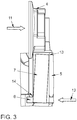
- FIG. 1 shows a wastegate, which is typically arranged on a housing 1 of the exhaust gas turbocharger.
- a bypass opening 9 is arranged, through which exhaust gas can be conducted past the turbine of the exhaust gas turbocharger.
- the bypass opening 9 can be closed and opened by means of a flap plate 4.
- the bypass opening 9 is shown open.
- the flap plate 4 is fixed to a spindle 7, which has a lever-like region for receiving the flap plate 4 and a wave-like region for supporting the spindle 7 in the housing 1.
- an articulation lever 6 is arranged at the housing outer side end of the spindle 7, which an articulation lever 6 is arranged. With the articulation lever 6 a push rod 2 is still connected via a coupling piece 3.
- the coupling piece 3 is rotatably attached to the articulation lever 6 about an axis parallel to the axis of the spindle 7.
- the coupling piece 3 has a through hole through which the push rod 2 is passed.
- the push rod 2 is fixed by means of threaded nuts in the coupling piece 3. By means of the push rod 2, the movement of an unspecified actuator is transmitted to the articulation lever 6 and the spindle 7 on the valve plate 4.
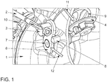
- Fig. 3 shows how a defined contact of the spindle 7 in a socket 5 is achieved by the reaction force FR 12.
- the bush 5 is arranged in the housing 1 and surrounds the spindle 7 to form a sliding bearing. Outside the housing, the reaction force FR 12 acts on the housing outer side end of the spindle 7.
- Fig. 2 illustrates the position of the stopper 8 at a substantially central height between the axis of the coupling piece 3 and the axis of the spindle 7.
- FR 12 is provided that the stop 8 with respect to its height in the middle third of the distance between the Axis of the coupling piece 3 and the axis of the spindle 7 is arranged.
- the stop 8 is to project perpendicular to the plane in which the axis of rotation of the coupling piece 3 and the axis of the spindle 7 are located.
Landscapes
- Engineering & Computer Science (AREA)
- Chemical & Material Sciences (AREA)
- Combustion & Propulsion (AREA)
- Mechanical Engineering (AREA)
- General Engineering & Computer Science (AREA)
- Chemical Kinetics & Catalysis (AREA)
- General Chemical & Material Sciences (AREA)
- Supercharger (AREA)
Abstract
Description
- Die Erfindung betrifft einen Abgasturbolader für eine Brennkraftmaschine, insbesondere für eine Brennkraftmaschine eines Kraftfahrzeugs.
- Abgasturbolader verfügen über ein Wastegate, welches dazu dient, in bestimmten Betriebszuständen, insbesondere bei großen Abgasmassenströmen, einen Teil des Abgases an der Turbine des Abgasturboladers vorbei zu leiten. Durch ein Wastegate kann demnach eine Überdrehzahl des Abgasturboladers verhindert werden. Weiterhin wird durch Öffnen des Wastegates der Abgasweg entdrosselt, wodurch ein ausreichender Massendurchsatz ermöglicht ist.
- Die
DE 10 2012 202 505 A1 beschreibt ein Wastegate eines Abgasturboladers. Um die Schwingungsanregung einer Wastegate-Klappe durch den Abgasstrom zu reduzieren, wenn nicht gar zu vermeiden, ist vorgesehen, dass die Wastegate-Klappe in geöffneter Stellung durch einen Anschlag abgestützt wird. Neben Anschlägen, welche sich unmittelbar an der Wastegate-Klappe abstützen, wird weiterhin ein Anschlag offenbart, welcher sich gegen den außerhalb des Turboladergehäuses angeordneten Hebel abstützt. Der Anschlag ist dabei im Wesentlichen in Höhe der Wirkrichtung der Kraft der Koppelstange angeordnet. - Durch das Anordnen des Anschlags im Wesentlichen in Wirkrichtung der Kraft der Koppelstange wird die durch die Koppelstange in den Hebel eingeleitete Kraft direkt durch eine zwischen Anschlag und Hebel wirkende Reaktionskraft aufgehoben. Da die Wirklinien der eingeleiteten Kraft und der Reaktionskraft keinen oder nur einen geringen Abstand zueinander aufweisen, wirkt auf den Hebel durch diese beiden Kräfte kein oder nur ein geringes Drehmoment. Dies bewirkt, dass das gehäuseaußenseitige Ende der Spindel bezogen auf die Querrichtung zur Spindelachse kraftfrei oder nahezu kraftfrei ist. Dadurch weist das gehäuseaußenseitige Ende der Spindel keine definierte Anlage in der spielbehafteten Lagerung auf. Die hohen Bauteiltemperaturen und Temperaturschwankungen im Betrieb und die daraus resultierende thermische Ausdehnung erfordern ein relativ großes Spiel zwischen Lagerung und Spindel. Im Betrieb können Motorschwingungen und Abgaspulsationen dazu führen, dass es innerhalb dieses Spiels zu schlagenden Bewegungen der Spindel gegen die Buchse kommt. Diese Anlagewechsel können zu Verschleiß führen.
- Aufgabe der vorliegenden Erfindung ist es, den Verschleiß einer Lagerung eines Wastegates in geöffneter Stellung zu reduzieren.
- Diese Aufgabe wird erfindungsgemäß durch einen Abgasturbolader für eine Brennkraftmaschine mit den Merkmalen gemäß Anspruch 1 gelöst. Vorteilhafte Weiterbildungen der Erfindung sind in den abhängigen Ansprüchen charakterisiert.
- Ein erfindungsgemäßer Abgasturbolader für eine Brennkraftmaschine weist ein Gehäuse mit einem außenseitig an dem Gehäuse angeordneten Anschlag auf. Der Anschlag kann als ein an dem Gehäuse befestigbares, zusätzliches Bauteil ausgeführt sein. In dem Gehäuse ist eine Bypassöffnung angeordnet, durch welche Abgas der Brennkraftmaschine strömen kann. Die Bypassöffnung kann dazu dienen, Abgas an einer Turbine des Abgasturboladers vorbeizuführen, so dass ein Abgasstrom über die Turbine steuer- oder auch regelbar ist.
- Der Abgasturbolader weist ein Wastegate mit einem Klappenteller auf. Der Klappenteller ist bezüglich seiner Form an die Bypassöffnung angepasst, so dass der Klappenteller bei Anlage an den Rändern der Bypassöffnung den Abgasstrom durch die Bypassöffnung verhindert oder nahezu verhindert. Dies wird als geschlossene Stellung des Wastegates bezeichnet. Der Klappenteller kann von der Bypassöffnung entfernt werden, wodurch das Wastegate geöffnet wird. Dazu ist der Klappenteller an einer Spindel angeordnet, welche durch das Gehäuse geführt und in diesem drehbar gelagert ist. An der Spindel kann ein Hebel zur Aufnahme des Klappentellers ausgebildet sein, so dass eine Drehung der Spindel im Gehäuse eine Bewegung des Klappentellers auf einer Kreisbahn in Richtung der Bypassöffnung oder von dieser weg verursacht.
- Außerhalb des Gehäuses ist an der Spindel ein Anlenkhebel angeordnet, welcher eine Drehung der Spindel erleichtert, indem er einen Hebelarm an der Spindel ausbildet. An dem Anlenkhebel ist ein Koppelstück angeordnet, welches mit einer Schubstange eines Aktuators verbindbar ist. Die Schubstange ist an dem Anlenkhebel in Abstand zu der Achse der Spindel drehbar um eine zu der Achse der Spindel parallele Achse anlenkbar. Die Benennung Koppelstück soll jegliche Entität bezeichnen, welche die Anbindung der Schubstange an den Anlenkhebel und die Drehung der Schubstange um den Anlenkpunkt ermöglicht. Dabei kann das Koppelstück auch als ein Teil der Schubstange oder ein Teil des Anlenkhebels ausgebildet sein.
- Eine maximal geöffnete Stellung des Wastegates ist dadurch gekennzeichnet, dass der Klappenteller in dieser Stellung die im ordnungsgemäßen Betrieb des Abgasturboladers größtmögliche Entfernung zu der Bypassöffnung aufweist. In dieser Stellung liegt der Anlenkhebel an dem Anschlag an, so dass der Anschlag eine weitere Öffnung des Wastegates verhindert. Erfindungsgemäß ist der Anschlag so angeordnet, dass er bei maximal geöffneter Stellung des Wastegates in im Wesentlichen mittiger Höhe zwischen der Achse des Koppelstücks und der Achse der Spindel positioniert ist. Zur Bestimmung der Höhe des Anschlags ist der Anschlag senkrecht auf die Ebene zu projizieren, in welcher die Drehachse des Koppelstücks und die Achse der Spindel liegen. Hieraus wird auch klar, dass nicht gemeint ist, dass der Anschlag in einer die Achse des Koppelstücks und die Achse der Spindel einschließenden Ebene angeordnet ist, da in dieser Ebene üblicherweise der Anlenkhebel angeordnet ist. Es soll aber auch nicht ausgeschlossen werden, dass bei entsprechender Gestaltung, beispielsweise einer Krümmung des Anlenkhebels, der Anschlag in dieser Ebene angeordnet sein kann.
- Durch den erfindungsgemäßen Abgasturbolader wird vorteilhaft erzielt, dass eine durch die Öffnung des Wastegates bedingte Schubstangen-Rückstellkraft, welche über das Koppelstück auf den Anlenkhebel wirkt, eine auf die Spindel wirkende Reaktionskraft verursacht. Diese auf das gehäuseaußenseitige Ende der Spindel wirkende Reaktionskraft entsteht aufgrund eines durch die Schubstangen-Rückstellkraft und den Anschlag erzeugten Drehmoments, welches auf den Anlenkhebel wirkt. Zusammen mit einer Gaskraft, welche durch den auf den Klappenteller wirkenden Abgasstrom auf das gehäuseinnenseitige Ende der Spindel wirkt, wird erfindungsgemäß eine definierte Anlage der Spindel in deren Lagerung erzielt. Diese Anlage wird vorteilhaft auch nicht durch Motorschwingungen und Abgaspulsationen aufgehoben, solange diese in der für einen ordnungsgemäßen Betrieb der Brennkraftmaschine üblichen Größenordnung bleiben.
Eine besonders große Reaktionskraft und somit eine besonders sichere Definition der Anlage der Spindel in der Lagerung kann dadurch erzielt werden, dass der Anschlag bezüglich seiner Höhe in den mittleren zwei Vierteln des Abstandes zwischen der Achse des Koppelstücks und der Achse der Spindel angeordnet ist. Bevorzugt ist der Anschlag bezüglich seiner Höhe in dem mittleren Drittel des Abstandes zwischen der Achse des Koppelstücks und der Achse der Spindel angeordnet, weiter bevorzugt in dem mittleren Fünftel angeordnet. Diese genauer eingeschränkte Anordnung des Anschlags kann beispielsweise durch die Höhe der Abgaspulsationen oder Motorschwingungen oder die Länge des Anlenkhebels erfoderlich sein. - Der Anschlag kann einstückig mit dem Gehäuse des Abgasturboladers ausgebildet sein, wodurch Kosten für ein zusätzliches Bauteil und dessen Befestigung eingespart werden können sowie die Toleranzkette für die Lage des Anschlags verbessert werden kann. Beispielsweise kann das Gehäuse des Abgasturboladers ein Gussbauteil sein, an welchem der Anschlag durch die Gussform bereits angeformt ist.
- Die Spindel kann direkt in dem Gehäuse gelagert sein. Zur Ermöglichung einer freieren Werkstoffwahl für die Materialpaarung der Lagerung kann aber auch eine Buchse in dem Gehäuse angeordnet sein, in welcher die Spindel gelagert ist. Durch eine Buchse kann die Verschleißcharakteristik der Spindellagerung verbessert werden, was zusammen mit der erfindungsgemäßen definierten Anlage der Spindel in der Lagerung eine synergetische Wirkung haben kann. Durch die definierte Anlage der Spindel in der geöffneten Stellung des Wastegates ergibt sich eine bessere und zuverlässigere Kenntnis der Belastung der Lagerung. Diese Kenntnis kann es ermöglichen, eine gezieltere Auswahl der Eigenschaften einer Buchse zu treffen.
- Weitere Vorteile und vorteilhafte Ausführungsformen und Weiterbildungen der Erfindung werden anhand der nachfolgenden Beschreibung unter Bezugnahme auf die Figuren dargestellt. Es zeigt im Einzelnen:
- Figur 1
- Eine perspektivische Darstellung einer Ausführungsform eines erfindungsgemäßen Abgasturboladers
- Figur 2
- Eine Seitenansicht der Ausführungsform der
Figur 1 - Figur 3
- Eine Draufsicht der Ausführungsform der
Figur 1 , wobei Gehäuse, Buchse, Anlenkhebel und ein Teil der Spindel geschnitten dargestellt sind -
Figur 1 zeigt ein Wastegate, welches typischerweise an einem Gehäuse 1 des Abgasturboladers angeordnet ist. Im Inneren des Gehäuses 1 ist eine Bypassöffnung 9 angeordnet, durch welche Abgas an der Turbine des Abgasturboladers vorbeileitbar ist. Die Bypassöffnung 9 ist mittels eines Klappentellers 4 verschließbar und öffenbar. InFig. 1 ist die Bypassöffnung 9 geöffnet dargestellt. Der Klappenteller 4 ist an einer Spindel 7 befestigt, welche einen hebelartigen Bereich zur Aufnahme des Klappentellers 4 und einen wellenartigen Bereich zur Lagerung der Spindel 7 in dem Gehäuse 1 aufweist. An dem gehäuseaußenseitigen Ende der Spindel 7 ist ein Anlenkhebel 6 angeordnet. Mit dem Anlenkhebel 6 ist weiterhin über ein Koppelstück 3 eine Schubstange 2 verbunden. Das Koppelstück 3 ist drehbar um eine zu der Achse der Spindel 7 parallele Achse an dem Anlenkhebel 6 befestigt. Das Koppelstück 3 weist eine Durchgangsbohrung auf, durch welche die Schubstange 2 hindurchgeführt ist. Die Schubstange 2 ist mittels Gewindemuttern in dem Koppelstück 3 festgelegt. Mittels der Schubstange 2 wird die Bewegung eines nicht näher beschriebenen Aktuators auf den Anlenkhebel 6 und über die Spindel 7 auf den Klappenteller 4 übertragen. - In der maximal geöffneten Position des Wastegates, wie in
Fig. 1 dargestellt, gibt der Klappenteller 4 die Bypassöffnung 9 maximal frei. In dieser Stellung wirkt eine Gaskraft FG 11 des strömenden Abgases auf den Klappenteller 4 in der mittels des Pfeils dargestellten Wirkrichtung. Eine Schubstangen-Rückstellkraft FF 10 wirkt in der dargestellten Richtung entlang der Achse der Schubstange 2 auf den Anlenkhebel 6. Der Anlenkhebel 6 kommt in der geöffneten Stellung des Wastegates an dem Anschlag 8 zur Anlage. Der Anschlag 8 liegt im Wesentlichen in mittiger Höhe zwischen der Achse des Koppelstücks 3 und der Spindel 7 an dem Anlenkhebel 6 an. Hierdurch wird bewirkt, dass eine Reaktionskraft FR 12 auf das gehäuseaußenseitige Ende der Spindel 7 wirkt. -
Fig. 3 zeigt, wie durch die Reaktionskraft FR 12 eine definierte Anlage der Spindel 7 in einer Buchse 5 erreicht wird. Die Buchse 5 ist in dem Gehäuse 1 angeordnet und umschließt die Spindel 7 zur Ausbildung einer Gleitlagerung. Im Inneren des Gehäuses wirkt die Gaskraft FG 11 auf den Klappenteller 4. Außerhalb des Gehäuses wirkt die Reaktionskraft FR 12 auf das gehäuseaußenseitige Ende der Spindel 7. Durch die im Wesentlichen gegensinnig gerichteten Kräfte wird die Spindel 7 in der Buchse 5 sowohl in eine definierte gehäuseinnenseitige Anlage 13 als auch in eine definierte gehäuseaußenseitige Anlage 14 gebracht. Kleinere Kräfte, beispielsweise durch Motorschwingungen oder Abgaspulsationen, können erfindungsgemäß nicht mehr einen Wechsel der Anlage bewirken. -
Fig. 2 verdeutlicht die Lage des Anschlags 8 auf im Wesentlichen mittiger Höhe zwischen der Achse des Koppelstücks 3 und der Achse der Spindel 7. Zur Erzielung einer ausreichend großen Reaktionskraft FR 12 ist vorgesehen, dass der Anschlag 8 bezüglich seiner Höhe in dem mittleren Drittel des Abstandes zwischen der Achse des Koppelstücks 3 und der Achse der Spindel 7 angeordnet ist. - Zur Bestimmung der Höhe des Anschlags 8 ist der Anschlag 8 senkrecht auf die Ebene zu projizieren, in welcher die Drehachse des Koppelstücks 3 und die Achse der Spindel 7 liegen.
-
- 1:
- Gehäuse
- 2:
- Schubstange
- 3:
- Koppelstück
- 4:
- Klappenteller
- 5:
- Buchse
- 6:
- Anlenkhebel
- 7:
- Spindel
- 8:
- Anschlag
- 9:
- Bypassöffnung
- 10:
- Schubstangen-Rückstellkraft FF
- 11:
- Gaskraft FG
- 12:
- Reaktionskraft FR
- 13:
- Gehäuseinnenseitige Anlage
- 14:
- Gehäuseaußenseitige Anlage
Claims (7)
- Abgasturbolader für eine Brennkraftmaschine, aufweisend ein Gehäuse (1) mit einem außenseitig an dem Gehäuse (1) angeordneten Anschlag (8) und einer in dem Gehäuse (1) angeordneten Bypassöffnung (9) und ein Wastegate mit einem Klappenteller (4), einer Spindel (7), einem Anlenkhebel (6) und einem Koppelstück (3), wobei der Klappenteller (8) zum wahlweisen Öffnen oder Schließen der Bypassöffnung (9) ausgebildet und in dem Gehäuse (1) an der Spindel (7) angeordnet ist, die Spindel (7) aus dem Gehäuse (1) herausgeführt und drehbar um eine Achse in diesem gelagert ist, der Anlenkhebel (6) außerhalb des Gehäuses (1) an der Spindel (7) angeordnet ist, das Koppelstück (3) außerhalb des Gehäuses (1) drehbar um eine Achse an dem Anlenkhebel (6) angeordnet und mit einer Schubstange (2) eines Aktuators verbindbar ist, wobei in einer maximal geöffneten Stellung des Wastegates der Anlenkhebel (6) an dem Anschlag (8) anliegt, dadurch gekennzeichnet, dass der Anschlag (8) in im Wesentlichen mittiger Höhe zwischen der Achse des Koppelstücks (3) und der Achse der Spindel (7) angeordnet ist, wenn das Wastegate in maximal geöffneter Stellung ist.
- Abgasturbolader für eine Brennkraftmaschine nach Anspruch 1, dadurch gekennzeichnet, dass der Anschlag (8) bezüglich seiner Höhe in den mittleren zwei Vierteln des Abstandes zwischen der Achse des Koppelstücks (3) und der Achse der Spindel (7) angeordnet ist.
- Abgasturbolader für eine Brennkraftmaschine nach Anspruch 1 oder 2, dadurch gekennzeichnet, dass der Anschlag (8) bezüglich seiner Höhe in dem mittleren Drittel des Abstandes zwischen der Achse des Koppelstücks (3) und der Achse der Spindel (7) angeordnet ist.
- Abgasturbolader für eine Brennkraftmaschine nach einem der vorhergehenden Ansprüche, dadurch gekennzeichnet, dass der Anschlag (8) bezüglich seiner Höhe in dem mittleren Fünftel des Abstandes zwischen der Achse des Koppelstücks (3) und der Achse der Spindel (7) angeordnet ist.
- Abgasturbolader für eine Brennkraftmaschine nach einem der vorhergehenden Ansprüche, dadurch gekennzeichnet, dass der Anschlag (8) einstückig mit dem Gehäuse (1) ausgebildet ist.
- Abgasturbolader für eine Brennkraftmaschine nach einem der vorhergehenden Ansprüche, dadurch gekennzeichnet, dass das Gehäuse (1) eine Buchse (5) umfasst, in welcher die Spindel (7) gelagert ist.
- Brennkraftmaschine mit einem Abgasturbolader gemäß einem der vorhergehenden Ansprüche.
Applications Claiming Priority (2)
| Application Number | Priority Date | Filing Date | Title |
|---|---|---|---|
| DE102016201365 | 2016-01-29 | ||
| DE102016210901.4A DE102016210901A1 (de) | 2016-06-17 | 2016-06-17 | Abgasturbolader für eine Brennkraftmaschine |
Publications (1)
| Publication Number | Publication Date |
|---|---|
| EP3199778A1 true EP3199778A1 (de) | 2017-08-02 |
Family
ID=57906467
Family Applications (1)
| Application Number | Title | Priority Date | Filing Date |
|---|---|---|---|
| EP17152737.7A Ceased EP3199778A1 (de) | 2016-01-29 | 2017-01-24 | Abgasturbolader für eine brennkraftmaschine |
Country Status (2)
| Country | Link |
|---|---|
| EP (1) | EP3199778A1 (de) |
| CN (1) | CN107035510A (de) |
Cited By (2)
| Publication number | Priority date | Publication date | Assignee | Title |
|---|---|---|---|---|
| EP3375999A1 (de) * | 2017-03-13 | 2018-09-19 | Toyota Jidosha Kabushiki Kaisha | Turbolader |
| US10914189B2 (en) * | 2017-02-14 | 2021-02-09 | Toyota Jidosha Kabushiki Kaisha | Turbocharger |
Families Citing this family (2)
| Publication number | Priority date | Publication date | Assignee | Title |
|---|---|---|---|---|
| DE102017219165B4 (de) * | 2017-10-25 | 2022-10-27 | Volkswagen Aktiengesellschaft | Verdichter, Abgasturbolader und Brennkraftmaschine |
| DE102018211095A1 (de) * | 2018-07-05 | 2020-01-09 | Volkswagen Aktiengesellschaft | Verfahren zum Betreiben eines Kraftfahrzeugs und Kraftfahrzeug |
Citations (6)
| Publication number | Priority date | Publication date | Assignee | Title |
|---|---|---|---|---|
| DE2828687A1 (de) * | 1977-07-20 | 1979-02-01 | Hess & Cie Pilgersteg | Schliessvorrichtung fuer gaskanaele, insbesondere belueftungskanaele |
| DE4439432C1 (de) * | 1994-11-04 | 1995-11-02 | Daimler Benz Ag | Abgasklapppe |
| JP2012140889A (ja) * | 2010-12-28 | 2012-07-26 | Isuzu Motors Ltd | 切替式二段過給機ターボシステム |
| DE102012202505A1 (de) | 2012-02-17 | 2013-08-22 | Mahle International Gmbh | Abgasturbolader für eine Brennkraftmaschine |
| EP2915975A1 (de) * | 2014-03-03 | 2015-09-09 | Honeywell International Inc. | Bypassventilmechanismus einer turboladerturbine |
| GB2530824A (en) * | 2015-02-13 | 2016-04-06 | Ford Global Tech Llc | Turbocharger wastegate linkage assembly |
Family Cites Families (3)
| Publication number | Priority date | Publication date | Assignee | Title |
|---|---|---|---|---|
| DE102010044683A1 (de) * | 2010-09-08 | 2012-03-08 | Volkswagen Ag | Abgasturbolader mit einem Bypassventil |
| JP2013007265A (ja) * | 2011-06-22 | 2013-01-10 | Ihi Corp | 多段過給システム |
| DE102011117339B4 (de) * | 2011-10-31 | 2023-09-28 | Bmw Ag | Abgasturbolader mit einem Wastegate-Ventil |
-
2017
- 2017-01-24 EP EP17152737.7A patent/EP3199778A1/de not_active Ceased
- 2017-02-03 CN CN201710063347.4A patent/CN107035510A/zh active Pending
Patent Citations (7)
| Publication number | Priority date | Publication date | Assignee | Title |
|---|---|---|---|---|
| DE2828687A1 (de) * | 1977-07-20 | 1979-02-01 | Hess & Cie Pilgersteg | Schliessvorrichtung fuer gaskanaele, insbesondere belueftungskanaele |
| DE4439432C1 (de) * | 1994-11-04 | 1995-11-02 | Daimler Benz Ag | Abgasklapppe |
| JP2012140889A (ja) * | 2010-12-28 | 2012-07-26 | Isuzu Motors Ltd | 切替式二段過給機ターボシステム |
| DE102012202505A1 (de) | 2012-02-17 | 2013-08-22 | Mahle International Gmbh | Abgasturbolader für eine Brennkraftmaschine |
| EP2915975A1 (de) * | 2014-03-03 | 2015-09-09 | Honeywell International Inc. | Bypassventilmechanismus einer turboladerturbine |
| GB2530824A (en) * | 2015-02-13 | 2016-04-06 | Ford Global Tech Llc | Turbocharger wastegate linkage assembly |
| DE102016102277A1 (de) * | 2015-02-13 | 2016-08-18 | Ford Global Technologies, Llc | Wastegate-gestängeanordnung für turbolader |
Cited By (3)
| Publication number | Priority date | Publication date | Assignee | Title |
|---|---|---|---|---|
| US10914189B2 (en) * | 2017-02-14 | 2021-02-09 | Toyota Jidosha Kabushiki Kaisha | Turbocharger |
| EP3375999A1 (de) * | 2017-03-13 | 2018-09-19 | Toyota Jidosha Kabushiki Kaisha | Turbolader |
| US10422275B2 (en) | 2017-03-13 | 2019-09-24 | Toyota Jidosha Kabushiki Kaisha | Turbocharger |
Also Published As
| Publication number | Publication date |
|---|---|
| CN107035510A (zh) | 2017-08-11 |
Similar Documents
| Publication | Publication Date | Title |
|---|---|---|
| DE112012002539B4 (de) | Stellkraft-Übertragungseinrichtung eines Abgasturboladers | |
| EP2247839B1 (de) | Turbolader mit einer betätigungseinrichtung zum öffnen und schliessen eines wastegate-kanals | |
| DE60014501T2 (de) | Schutzvorrichtung für den Stellantrieb der Statorschaufelblätter eines Turbostrahltriebwerks | |
| EP2630352B1 (de) | Betätigungsvorrichtung für eine abgasklappe | |
| DE102012105402B4 (de) | Verstellvorrichtung für einen Abgasturbolader | |
| EP2791487B1 (de) | Betätigungseinrichtung für eine turbine eines abgasturboladers | |
| EP2534349A1 (de) | Betätigungseinrichtung für ein ventil, insbesondere ein waste-gate eines abgasturboladers | |
| DE2610243A1 (de) | Durchflussregelventil | |
| DE102016204076A1 (de) | Abgasturbolader | |
| EP3199778A1 (de) | Abgasturbolader für eine brennkraftmaschine | |
| DE102011089777A1 (de) | Abgasturbolader mit zumindest einem Bypass-Ventil | |
| EP2803838B1 (de) | Abgasturbolader-Anordnung | |
| DE102018127809B4 (de) | Turbolader-wastegate-stellgliedanordnung | |
| DE102006021185A1 (de) | Verschlussklappe für einen Abgasturbolader | |
| DE102012202505A1 (de) | Abgasturbolader für eine Brennkraftmaschine | |
| DE102004058719A1 (de) | Abgasturbolader mit variabler Turbinengeometrie | |
| EP2573357A1 (de) | Klappenvorrichtung für ein Turbolder-Wastegateventil | |
| DE102007050818A1 (de) | Brennkraftmaschine | |
| EP3320202B1 (de) | Drei-wege-abgasrückführungs-ventilanordnung mit drei fluidöffnungen für eine abgasrückführung | |
| DE102016210901A1 (de) | Abgasturbolader für eine Brennkraftmaschine | |
| EP2657480A1 (de) | Abgasturbolader für eine Brennkraftmaschine | |
| DE102011011451B4 (de) | Betätigungseinrichtung für einen Abgasturbolader | |
| DE102008022468B4 (de) | Ladeeinrichtung | |
| DE20311260U1 (de) | Absperranordnung zum Absperren eines Fluidstroms | |
| DE102013103507A1 (de) | Regelvorrichtung für einen Abgasführungsabschnitt einer Turbine |
Legal Events
| Date | Code | Title | Description |
|---|---|---|---|
| PUAI | Public reference made under article 153(3) epc to a published international application that has entered the european phase |
Free format text: ORIGINAL CODE: 0009012 |
|
| AK | Designated contracting states |
Kind code of ref document: A1 Designated state(s): AL AT BE BG CH CY CZ DE DK EE ES FI FR GB GR HR HU IE IS IT LI LT LU LV MC MK MT NL NO PL PT RO RS SE SI SK SM TR |
|
| AX | Request for extension of the european patent |
Extension state: BA ME |
|
| 17P | Request for examination filed |
Effective date: 20180202 |
|
| RBV | Designated contracting states (corrected) |
Designated state(s): AL AT BE BG CH CY CZ DE DK EE ES FI FR GB GR HR HU IE IS IT LI LT LU LV MC MK MT NL NO PL PT RO RS SE SI SK SM TR |
|
| 17Q | First examination report despatched |
Effective date: 20180430 |
|
| STAA | Information on the status of an ep patent application or granted ep patent |
Free format text: STATUS: THE APPLICATION HAS BEEN REFUSED |
|
| 18R | Application refused |
Effective date: 20191031 |