EP3199703A1 - Railroad track tool apparatus - Google Patents
Railroad track tool apparatus Download PDFInfo
- Publication number
- EP3199703A1 EP3199703A1 EP16185566.3A EP16185566A EP3199703A1 EP 3199703 A1 EP3199703 A1 EP 3199703A1 EP 16185566 A EP16185566 A EP 16185566A EP 3199703 A1 EP3199703 A1 EP 3199703A1
- Authority
- EP
- European Patent Office
- Prior art keywords
- rail
- tool
- clamp assembly
- coupling
- pivot
- Prior art date
- Legal status (The legal status is an assumption and is not a legal conclusion. Google has not performed a legal analysis and makes no representation as to the accuracy of the status listed.)
- Granted
Links
Images


Classifications
-
- E—FIXED CONSTRUCTIONS
- E01—CONSTRUCTION OF ROADS, RAILWAYS, OR BRIDGES
- E01B—PERMANENT WAY; PERMANENT-WAY TOOLS; MACHINES FOR MAKING RAILWAYS OF ALL KINDS
- E01B31/00—Working rails, sleepers, baseplates, or the like, in or on the line; Machines, tools, or auxiliary devices specially designed therefor
- E01B31/02—Working rail or other metal track components on the spot
- E01B31/12—Removing metal from rails, rail joints, or baseplates, e.g. for deburring welds, reconditioning worn rails
- E01B31/17—Removing metal from rails, rail joints, or baseplates, e.g. for deburring welds, reconditioning worn rails by grinding
-
- B—PERFORMING OPERATIONS; TRANSPORTING
- B24—GRINDING; POLISHING
- B24B—MACHINES, DEVICES, OR PROCESSES FOR GRINDING OR POLISHING; DRESSING OR CONDITIONING OF ABRADING SURFACES; FEEDING OF GRINDING, POLISHING, OR LAPPING AGENTS
- B24B19/00—Single-purpose machines or devices for particular grinding operations not covered by any other main group
- B24B19/004—Single-purpose machines or devices for particular grinding operations not covered by any other main group for grinding rails, T, I, H or other similar profiles
-
- B—PERFORMING OPERATIONS; TRANSPORTING
- B24—GRINDING; POLISHING
- B24B—MACHINES, DEVICES, OR PROCESSES FOR GRINDING OR POLISHING; DRESSING OR CONDITIONING OF ABRADING SURFACES; FEEDING OF GRINDING, POLISHING, OR LAPPING AGENTS
- B24B23/00—Portable grinding machines, e.g. hand-guided; Accessories therefor
- B24B23/02—Portable grinding machines, e.g. hand-guided; Accessories therefor with rotating grinding tools; Accessories therefor
-
- B—PERFORMING OPERATIONS; TRANSPORTING
- B24—GRINDING; POLISHING
- B24B—MACHINES, DEVICES, OR PROCESSES FOR GRINDING OR POLISHING; DRESSING OR CONDITIONING OF ABRADING SURFACES; FEEDING OF GRINDING, POLISHING, OR LAPPING AGENTS
- B24B23/00—Portable grinding machines, e.g. hand-guided; Accessories therefor
- B24B23/08—Portable grinding machines designed for fastening on workpieces or other parts of particular section, e.g. for grinding commutators
-
- B—PERFORMING OPERATIONS; TRANSPORTING
- B24—GRINDING; POLISHING
- B24B—MACHINES, DEVICES, OR PROCESSES FOR GRINDING OR POLISHING; DRESSING OR CONDITIONING OF ABRADING SURFACES; FEEDING OF GRINDING, POLISHING, OR LAPPING AGENTS
- B24B27/00—Other grinding machines or devices
- B24B27/0084—Other grinding machines or devices the grinding wheel support being angularly adjustable
Definitions
- the present disclosure relates to a railroad track tool apparatus that can be mounted on a railroad track rail to perform an operation on the rail.
- Devices configured to support a manually operated tool on railroad tracks are known. Typically, these devices rest on rollers positioned top of one or both rails of a railroad track and are manually pushed, pulled, lifted, and twisted with physical difficulty by users to position the manually operated tool relative to the track.
- the apparatus comprises a tool, a clamp assembly, a coupling, and/or other components.
- the tool is configured to perform an operation to a rail of a railroad track.
- the coupling is configured to couple the tool to the clamp assembly.
- the clamp assembly is moveable between a clamped position and an unclamped position to removably couple the tool with the rail.
- the clamp assembly comprises a first bearing structure configured to engage an upper side of the rail, and second and third bearing structures configured to engage an underside of the rail when the clamp assembly is in the clamped position.
- the clamp assembly is moveable along the rail.
- the clamp assembly further comprises fourth and fifth bearing structures configured to move along an inner side and an outer side of the rail to facilitate the movement of the clamp assembly along the rail without binding against the rail, a lever, an adjustment structure, and/or other components.
- the second and third bearing structures rotate toward the rail to engage the underside of the rail and rotate away from the rail to disengage the underside of the rail.
- the lever is configured to, when actuated by a user, cause the second and third bearing structures to engage or disengage the underside of the rail.
- the adjustment structure is configured to adjust a distance between a sixth bearing structure and the second and third bearing structures.
- the apparatus comprises the tool, the clamp assembly, the coupling, and/or other components.
- the tool is configured to perform the operation to the rail of the railroad track.
- the clamp assembly is configured to removably couple the tool with the rail.
- the coupling is configured to couple the tool to the clamp assembly.
- the coupling comprises a pivot that couples the coupling to the clamp assembly. The pivot is configured to facilitate rotation of the coupling to move the tool between an inner side and an outer side of the rail.
- the clamp assembly is configured such that the second, third, and sixth bearing structures are disposed toward a first end of the clamp assembly; the first, fourth, and fifth bearing structures are disposed toward a second end of the clamp assembly; and the coupling is coupled to the clamp assembly toward the second end of the clamp assembly near the first, fourth, and fifth bearing structures.
- the first end of the clamp assembly is clamped to the rail and the pivot couples the coupling to the clamp assembly toward the second end of the clamp assembly.
- the coupling has a first end and a second end opposite the first end, and the coupling is coupled to the clamp assembly via the pivot toward the first end of the coupling.
- the clamp assembly extends along the rail from the first end of the clamp assembly to the second end of the clamp assembly, and the pivot is positioned above the rail and couples the coupling to the clamp assembly toward the second end of the clamp assembly.
- the pivot includes a hard stop and a retractable detent configured to limit rotation of the coupling.
- the hard stop and retractable detent are configured to allow enough rotation of the coupling such that the tool is positionable on the inner side or the outer side of the rail.
- the apparatus comprises the tool configured to perform the operation to the rail of the railroad track, the clamp assembly configured to removably couple the tool with the rail, the coupling configured to couple the tool to the clamp assembly, and/or other components.
- the coupling comprises a linkage assembly configured to facilitate movement of the tool toward and away from the rail.
- the linkage assembly includes a spring structure. A gravitational weight of the tool is countered by a spring force provided by the spring structure. This may, for example, make it easier for a user to manipulate the tool.
- the linkage assembly is moved by the user via a tool handle to move the tool toward and away from the rail.
- the linkage assembly comprises a four bar link assembly.
- the spring structure of the linkage assembly includes a gas spring, a tension spring, a compression spring, a torsion spring, and/or other springs.
- the four bar link assembly and the gas spring are configured to support the weight of the tool such that the perceived weight of the tool felt by the user is reduced compared to the actual weight of the tool.
- the coupling includes a pivot and the linkage assembly comprises an arm coupled to the clamp assembly via the pivot.
- the pivot is configured to facilitate rotation of the arm to move the tool between the inner side and the outer side of the rail.
- the arm has a first end and a second end opposite the first end, and the arm is coupled to the clamp assembly via the pivot toward the first end of the arm.
- the arm extends away from the pivot, and the tool is coupled with the coupling toward the second end of the arm.
- the arm is moved by the user (via the tool handle) to position the tool on the outer side or the inner side of the rail.
- the apparatus comprises the tool configured to perform the operation to the rail of the railroad track, the clamp assembly configured to removably couple the tool with the rail, the coupling configured to couple the tool to the clamp assembly, and/or other components.
- the coupling comprises a head configured to couple with the tool and/or other components.
- the head is configured to rotate about a first axis such that the tool is moveable toward and away from the inner side or the outer side of the rail, and rotate about a second axis such that the tool is moveable toward and away from the underside of the rail.
- the head comprises a gimbal rotation mechanism.
- the tool is coupled to the gimbal rotation mechanism via a bearing and/or other coupling devices.
- the gimbal rotation mechanism may be configured with two axis of rotation (e.g., a double gimbal rotation mechanism).
- the gimbal rotation mechanism includes a base, an inner gimbal rotation mechanism, an outer gimbal rotation mechanism, and/or other components.
- the inner gimbal rotation mechanism and the outer gimbal rotation mechanism are coupled via revolute joints.
- the description herein of the double gimbal rotation mechanism is not intended to be limiting.
- the gimbal rotation mechanism may be a three axis rotation mechanism including any components and/or having any structure configured for three axis rotation.
- the head further comprises a hard stop and a retractable pin lock that limit the rotation of the head about the second axis.
- the head is configured such that the first axis is a substantially vertical axis and the second axis is a substantially horizontal axis relative to the rail.
- the tool is a grinder, an inspection device, and/or other tools.
- the operation performed by the tool to the railroad track comprises a grinding operation, an inspection operation, and/or other operations.
- the tool is coupled with the coupling toward the second end of the coupling.
- FIG. 1 illustrates a railroad track tool apparatus 10.
- Apparatus 10 can be mounted on a railroad track rail 6 to perform an operation on rail 6.
- Apparatus 10 comprises a manually operated tool 8, a clamp assembly 12, a coupling 14, and/or other components.
- Clamp assembly 12, coupling 14, and/or other components of apparatus 10 provide support to the manually operated tool 8 and/or other tools for working on and/or around railroad tracks.
- Apparatus 10 couples with a single rail 6 of a railroad track instead of straddling and/or being otherwise coupled with both rails of the railroad track.
- Clamp assembly 12, coupling 14, and/or other components of apparatus 10 enable manipulation and articulation of tool 8 by an operator working on the railroad track (and/or other operators) to facilitate access to various areas of the railroad track (e.g., an underside 30 of rail 6).
- Clamp assembly 12 is located at a first end 50 of apparatus 10.
- Clamp assembly 12 extends along rail 6 from a first end 52 of clamp assembly 12 to a second end 54 of clamp assembly 12.
- clamp assembly has a length 56 of up to about 15 inches.
- length 56 is between about 11 inches and about 15 inches.
- length 56 is about 13 inches.
- Clamp assembly 12 clamps around an inner side 32 and an outer side 34 of rail 6 and engages an upper side 36 and underside 30 of rail 6.
- Clamp assembly 12 is moveable along rail 6.
- Clamp assembly 12 is moveable along rail 6 such that a user may move tool 8 back and forth along rail 6 to perform an operation to the rail 6 at any location on rail 6 (and/or on the other rail of the railroad track).
- FIG. 2A illustrates a sectional side view (e.g., looking from inner side 32) of clamp assembly 12.
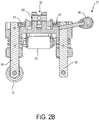
- FIG. 2B illustrates a sectional end view (e.g., looking from second end 54) of clamp assembly 12.
- FIG. 2C illustrates a sectional top view of clamp assembly 12.
- FIG. 2D illustrates another sectional end view (e.g., looking from first end 52) of clamp assembly 12.
- Clamp assembly 12 is illustrated in a clamped position 60 in FIG. 2E and an unclamped position 62 in FIG. 3 .
- clamp assembly 12 comprises a first (e.g., primary) bearing structure 59, second and third bearing structures 72 and 74, fourth and fifth bearing structures 78, 80, and a sixth bearing structure 70.
- Bearing structures 59, 72, 74, 78, 80, and 70 are shown in the figures and described herein as rollers (e.g., first roller 59, second and third rollers 72 and 74, fourth and fifth rollers 78 and 80, and sixth roller 70). This is not intended to be limiting.
- Bearing structures 59, 72, 74, 78, 80, and 70 may be and/or include any devices that allow clamp assembly 12 to move along rail 6 as described herein.
- bearing structures 59, 72, 74, 78, 80, and 70 may be and/or include rollers and/or other rollable bearings, reduced friction surfaces (e.g., metal and/or polymer), sliding components, and/or other bearing structures.
- First roller/bearing structure 59 is configured to engage upper side 36 ( FIG. 4 ) of rail 6, and second 72 and third 74 rollers/bearing structures are configured to engage underside 30 of rail 6 when clamp assembly 12 is in clamped position 60 ( FIG. 2E , FIG. 4 ).
- Apparatus 10 ( FIG. 1 ) pivots about first roller 59.
- Rollers 72 and 74 are located toward first end 52 of clamp assembly 12 ( FIG. 1 , 2B ). Rollers 72 and 74 may react against vertical components of a moment created by tool 8 via coupling 14 on clamp assembly 12, for example, and/or perform other functions.
- rail 6 may have a substantially "T" shaped cross section ( FIG. 4 ).
- second roller 72 is located on inner side 32 of rail 6 ( FIG. 4 ) and third roller 74 is located on outer side 34 of rail 6 ( FIG. 4 ).
- Second 72 and third 74 rollers rotate 76 ( FIG. 2E , FIG. 3 ) toward rail 6 about axes of rotation 71 and 73 respectively to engage underside 30 of rail 6.
- Second 72 and third 74 rollers rotate 75 away from rail 6 to disengage underside 30 of rail 6.
- Clamp assembly 12 may be installed on and/or removed from rail 6 when clamp assembly 12 is in unclamped position 62 ( FIG. 3 ).
- rollers 72, 74 may fit around and/or may be maneuvered to fit around the wide portion of the "T" shape of rail 6 to install and/or remove clamp assembly 12 from rail 6.
- Rollers 72, 74 may be positioned under the wide portion of the "T" of rail 6 on underside 30 of rail 6 in clamped position 60 (e.g., as shown in FIG. 4 ).
- a distance 77 between second and third rollers 72, 74 may be up to about 2 inches when clamp assembly 12 is in clamped position 60 ( FIG. 2E ). In some embodiments, distance 77 may be between about 1 inch and about 2 inches. In some embodiments, distance 77 may be about 1.44 inches. In some embodiments, a distance 79 between second and third rollers 72, 74 may be up to about 4 inches when clamp assembly 12 is in unclamped position 62 ( FIG. 3 ). In some embodiments, distance 79 is between about 2 inches and about 4 inches. In some embodiments, distance 79 is about 3.25 inches. However, distances 77 and 79 are not intended to be limiting.
- Distance 77 may be any distance that allows clamp assembly 12 to be clamped to rail 6 in clamped position 60 ( FIG. 2E ).
- Distance 79 may be any distance that allows clamp assembly 12 to be installed and/or removed from rail 6 when clamp assembly 12 is in unclamped position 62 ( FIG. 3 ).
- Distances 77 and 79, and/or other distances, may be adjusted and/or changed based on the dimensions of rail 6 such that apparatus 10 functions as described herein.
- FIG. 5 illustrates a side view (e.g., looking from outer side 34) of clamp assembly 12.
- FIG. 6 illustrates a perspective view of first end 52 of clamp assembly 12.
- clamp assembly 12 comprises fourth 78 ( FIG. 1 ) and fifth 80 rollers/bearing structures, sixth roller/bearing structure 70, a lever 90, an adjustment structure 92, and/or other components.
- Fourth and fifth rollers 78, 80 are configured to roll along inner side 32 (fourth roller 78) and outer side 34 (fifth roller 80) of rail 6 to facilitate movement of clamp assembly 12 along rail 6 without binding against rail 6.
- Sixth roller 70 is configured to roll along upper side 36 of rail 6 when clamp assembly 12 moves.
- Sixth roller 70 is an adjustment roller (described below) for different rail head sizes and provides a reaction point when clamp assembly 12 is travelling back and forth on rail 6.
- First roller 59, and fourth and fifth rollers 78, 80 are located toward second end 54 of clamp assembly 12 ( FIG. 5 ).
- second roller 74 and fifth roller 80 are separated by a distance 81 (between roller centers) of up to about 10 inches. In some embodiments, distance 81 is between about 6 inches and about 10 inches. In some embodiments, distance 81 is about 8.25 inches.
- Lever 90 and adjustment structure 92 are located toward first end 52 of clamp assembly 12 and disposed above upper side 36 of rail 6.
- Lever 90 is configured to, when actuated by a user, cause the second 72 and third 74 rollers to engage and/or disengage underside 30 of rail 6 ( FIG. 5 ).
- Lever 90 causes the second 72 and third 74 rollers to rotate 76 about respective axes of rotation 71 (second roller 72) and 73 (third roller 74) toward rail 6 to engage rail 6 and rotate 75 (about the same axes) away from rail 6 to disengage rail 6.
- rollers 72 and 74 rotate about 90° in substantially opposite directions (e.g., roller 72 rotates toward second end 54 ( FIG. 1 ) and roller 74 rotates toward first end 52 ( FIG.
- lever 90 may be rotated about 90° (this angle is not intended to be limiting) in a clockwise direction (this direction is not intended to be limiting) to cause rollers 72 and 74 to engage rail 6, and about 90° (this angle is not intended to be limiting) in a counterclockwise direction (this direction is not intended to be limiting) to cause rollers 72 and 74 to disengage rail 6.
- Lever 90 may cause rotation of rollers 72, 74 by way of one or more axles 91 and/or other components.
- One or more axles 91 may be coupled with rollers 72, 74.
- Lever 90 may be coupled with one or more axles 91 (e.g., by axle coupling components 93 shown in FIG. 6 ) and cause rotation of axles 91 when lever 90 is actuated by a user. For example, actuation of lever 90 by a user may in turn cause rotation of axles 91, which then cause rotation of rollers 72, 74.
- Lever 90 may be coupled with axles 91 and/or axles 91 may be coupled with rollers 72, 72 via one or more axle coupling components 93 such as brackets, nuts, bolts, screws, fasteners, clamps, clips, hinges, sleeves, blocks, dowels, pins, and/or other coupling devices 93. For example, as shown in in FIG.
- lever 90 may be directly coupled with an axle 91 that is coupled with roller 72.
- Lever 90 may be indirectly coupled via axle coupling components 93 with an axle 91 that rotates roller 74.
- spring loaded detents 67 (only the detent along axis 73 is shown in FIG. 6 but this is not intended to be limiting) engage axles 91 along axes 71 and 73 to secure lever 90 in place after the rollers are moved to the desired location (e.g., clamped or unclamped).
- Adjustment structure 92 is configured to adjust a distance 102 ( FIG. 5 ) along inner side 32/outer side 34 between sixth roller 70 and second and third rollers 72, 74.
- Distance 102 may be adjusted by a user via a handle 104 and/or other components of adjustment structure 92.
- adjustment structure 92 may include a threaded rod 65 (shown in FIG. 1D and 1E ) which pushes and/or pulls a link 63 coupled with roller 70 to adjust distance 102 and/or other distances.
- Distance 102 may be adjusted based on the dimensions of rail 6 and/or for other reasons.
- coupling 14 is configured to couple tool 8 to clamp assembly 12.
- coupling 14 includes a pivot 16, a linkage assembly 160, a head 20, and/or other components.
- clamp assembly 12 is configured such that second, third, and sixth rollers 70, 72, 74 ( FIG. 2E ) are disposed toward first end 52 of clamp assembly 12; and first, fourth, and fifth rollers 59, 78, 80 ( FIG. 5 ) are disposed toward second end 54 of clamp assembly 12.
- Coupling 14 is coupled to clamp assembly 12 toward second end 54 of clamp assembly 12 near first, fourth, and fifth rollers 59, 78, 80.
- Pivot 16 and/or other components couple coupling 14 to clamp assembly 12.
- Pivot 16 is configured to facilitate rotation 130, about an axis of rotation 131, of coupling 14 to move tool 8 between inner side 32 and outer side 34 of rail 6.
- Pivot 16 couples coupling 14 to clamp assembly 12 toward second end 54 of clamp assembly 12.
- Coupling 14 has a first end 120 and a second end 122 opposite first end 120.
- Coupling 14 is coupled to clamp assembly 12 via pivot 16 toward first end 120 of coupling 14.
- Pivot 16 is positioned above rail 6 and couples coupling 14 to clamp assembly 12 toward second end 54 of clamp assembly 12 and first end 120 of coupling 14.
- pivot 16 may be and/or include a cylindrical joint and/or other joints that facilitate rotation.
- pivot 16 may include a cylindrical portion 132, a collar portion 134, and/or other portions.
- Cylindrical portion 132 may extend from clamp assembly 12 away from upper side 36 of rail 6 in a direction along axis 131 that is substantially normal (e.g., perpendicular) to upper side 36 of rail 6.
- cylindrical portion 132 may be and/or form a portion of clamp assembly 12.
- cylindrical portion 132 may be coupled with clamp assembly 12 via one or more cylinder coupling components 137 such as brackets, nuts, bolts, screws, fasteners, clamps, clips, hinges, sleeves, blocks, dowels, pins, and/or other coupling devices ( FIG. 2E , 3 , 5 ).
- Collar portion 134 is movably coupled with cylindrical portion 132 such that collar portion 134 rotates 130 around cylindrical portion 132 to facilitate the movement of tool 8 between inner side 32 and outer side 34 of rail 6 (e.g., via coupling portions 138 of collar portion 134 and arm 18 described below).
- pivot 16 includes a hard stop and/or a retractable detent configured to limit rotation of coupling 14.
- Hard stop / retractable detent 140 is illustrated in FIG. 7.
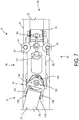
- FIG. 7 illustrates a top view of clamp assembly 12 and a portion of coupling 14 that includes pivot 16.
- Hard stop / retractable detent 140 may be configured to engage collar portion 134 to limit rotation of collar portion 134 around cylindrical portion 132.
- hard stop / retractable detent 140 is configured to allow enough rotation of coupling 14 such that tool 8 is positionable on inner side 32 or outer side 34 of rail 6 without unclamping clamping assembly 12 from rail 6.
- hard stop / retractable detent 140 may allow up to about 180° of rotation (e.g., with about 90° of rotation on either side of rail 6). In some embodiments, hard stop / retractable detent 140 may allow up to about 90° of rotation (e.g., with about 45° of rotation on either side of rail 6). In some embodiments, hard stop / retractable detent 140 may allow up to about 45° of rotation (e.g., with about 22.5° of rotation on either side of rail 6).
- linkage assembly 160 is coupled to clamp assembly 12.
- Linkage assembly 160 is coupled to clamp assembly 12 via pivot 16 and/or other coupling devices.
- linkage assembly 160 is coupled to pivot 16 via one or more coupling portions 138 of collar portion 134.
- Linkage assembly 160 may be coupled to coupling portions 138 via coupling mechanisms 139 such as brackets, nuts, bolts, screws, fasteners, clamps, clips, hinges, sleeves, blocks, dowels, pins, and/or other coupling mechanisms.
- Linkage assembly 160 is moveable (e.g., by a user) in three dimensions to position tool 8 ( FIG. 1 ) on outer side 34 or inner side 32 of rail 6, above or below upper side 36 of rail 6, and/or in other locations.
- Arm 18 has a first end 150 and a second end 152 ( FIG. 1 ) opposite first end 150.
- linkage assembly 160 comprises an arm 18. Arm 18 is coupled to clamp assembly 12 via pivot 16 toward first end 150 of arm 18. Arm 18 extends away from pivot 16, and tool 8 is coupled with coupling 14 toward second end 152 of arm 18.
- arm 18 has a length 154 ( FIG. 1 ) of up to about 18 inches. In some embodiments, length 154 is between about 12 inches and about 18 inches. In some embodiments, length 154 is about 14 inches.
- arm 18 has a width 156 of up to about 6 inches. In some embodiments, width 156 is between about 2 inches and about 6 inches. In some embodiments, width 156 is about 4 inches.
- FIG. 8 illustrates a side view of apparatus 10 (e.g., viewed from inner side 32 of rail 6).
- linkage assembly 160 is configured to facilitate movement of tool 8 relative to rail 6.
- Linkage assembly 160 includes a spring structure 161, wherein a gravitational weight of tool 8 is countered by a spring force provided by spring structure 161. This may make it easier for a user to manipulate tool 8, for example.
- linkage assembly 160 comprises a four bar link assembly.
- the four bar link assembly includes one or more upper bars 176, one or more lower bars 178, a gas spring 170, and/or other components.
- the description of gas spring 170 is not intended to be limiting.
- gas spring 170 may be any type of spring that functions as described herein (e.g., a tension spring, a compression spring, a torsion spring, and/or other springs).
- One side of the four bar link assembly toward pivot 16 may be formed by collar portion 134 of pivot 16.
- An opposite side of the four bar link assembly toward head 20 may be formed by a coupling portion 183 of head 20.
- Upper and lower bars 176, 178, and/or gas spring 170 may extend along arm 18 between pivot 16 and head 20.
- Upper and lower bars 176, 178 may be coupled with pivot 16 via collar portion 134 and/or head 20 via coupling portion 183 such that upper and lower bars 176 and 178 remain substantially parallel to each other when arm 18 is moved.
- Upper and lower bars 176, 178 may be coupled with pivot 16 and head 20 such that an angle 180 between pivot 16 and arm 18 and/or an angle 182 between arm 18 and tool 8 changes during movement.
- Gas spring 170 may comprise a compressed gas contained in a cylinder, a piston that moves within the cylinder to compress and/or decompress the gas, and/or other components that cause gas spring 170 (e.g., and/or other springs as described above) to exert the spring force that counters the gravitational weight (e.g., the gravitational reaction force) of tool 8.
- the spring force provided by gas spring 170 may be translated via the other components of system 10 (e.g., head 20, arm 18, pivot 16, clamp assembly 12) to the user manipulating tool 8 via handle 7, which may help the user manipulate tool 8.
- Gas spring 170 may be coupled to upper bar 176 and/or lower bar 178 such that an angle 184 between gas spring 170 and upper and lower bars 176 and 178 changes when arm 18 is moved by a user.
- Four bar link assembly 172 including gas spring 170 is configured to support the weight of tool 8 such that the perceived weight of tool 8 felt by the user is reduced compared to the actual weight of tool 8. This may make tool 8 easier to manipulate and/or otherwise move (e.g., via handle 7) for a user, and/or have other purposes.
- four bar link assembly 172 may be formed by portions of pivot 16 (e.g., collar portion 134), head 20 (coupling portion 183), coupling mechanisms that couple these components together, and/or other components of system 10.
- pivot 16 e.g., collar portion 134
- head 20 coupled to head 20
- coupling portion 183 coupling mechanisms that couple these components together, and/or other components of system 10.
- gas spring 170 may be and/or include a tension spring, a compression spring, a torsion spring, and/or other springs.
- the weight of tool 8 and/or arm 18 may be applied to spring 170 via a lower mounting point 61 ( FIG. 8 ), and/or an upper mounting point formed by coupling portions 138 and/or coupling mechanisms 139 (shown in FIG. 5 ).
- Rotational loads may be carried by one or more components including bars 176, 178, collar portion 134, coupling devices 199 ( FIG. 9 described below), and/or other components.
- FIG. 9 illustrates an end view of apparatus 10 (e.g., looking from a second end 51 (shown in FIG. 1 ) of apparatus 10).
- FIG. 9 illustrates head 20 coupled with coupling 14 at second end 152 of arm 18.
- Head 20 couples tool 8 to coupling 14 toward second end 51 of apparatus 10.
- Head 20 may be coupled with coupling 14 via one or more head coupling devices 199 such as brackets, nuts, bolts, screws, fasteners, clamps, clips, hinges, sleeves, blocks, dowels, pins, and/or other coupling devices. As shown in FIG.
- head 20 is configured to rotate 200 about a first axis 202 such that tool 8 is moveable toward and away from inner side 32 or outer side 34 of rail 6 (tool 8 is shown positioned on outer side 34 of rail 6 in FIG. 9 ), and rotate 204 about a second axis 206 such that tool 8 is moveable toward and away from underside 30 of rail 6 (e.g., allowing tool 8 to reach underneath the wide portion of the "T" shape of rail 6 described above).
- head 20 comprises a gimbal rotation mechanism 210.
- gimbal rotation mechanism 210 is a double gimbal rotation mechanism.
- Tool 8 is coupled to gimbal rotation mechanism 210 via a bearing and/or other coupling devices.
- Such coupling devices may include a sealed bearing and/or other bearings, for example. This may allow gimbal rotation mechanism 210 to rotate about axis 202 for example.
- Gimbal rotation mechanism 210 may include a base, an inner gimbal rotation mechanism, an outer gimbal rotation mechanism, and/or other components. The inner gimbal rotation mechanism and the outer gimbal rotation mechanism may be coupled via revolute joints and/or other mechanisms.
- axis 202 may be a primary axis of rotation and axis 206 may be a second selectable axis of rotation. It should be noted that the description herein of the double gimbal rotation mechanism is not intended to be limiting.
- the gimbal rotation mechanism may be a three axis rotation mechanism including any components and/or having any structure configured for three axis rotation.
- head 20 comprises a hard stop and a retractable pin lock that limit the rotation of head 20 about axis 206.
- Head 20 may be configured such that first axis 202 is a substantially vertical axis and second axis 206 is a substantially horizontal axis relative to rail 6.
- head 20 may be configured to rotate 200 360 degrees about first axis 202.
- head 20 may be configured to rotate 204 about second axis 206 up to about +/- 45 degrees in either direction around axis 206.
- head 20 may be configured to rotate about second axis 206 from between about +/- 10 degrees to about +/- 45 degrees in either direction around second axis 206.
- head 20 may be configured to rotate 204 about second axis 206 about +/- 20 degrees in either direction around axis 206.
- tool 8 is configured to perform an operation to rail 6 of the railroad track.
- tool 8 is configured to perform the operation to both rails (e.g., one rail at a time) of the railroad track while remaining mounted to only rail 6.
- tool 8 may be mounted to rail 6 and used to perform the operation on rail 6, but then stretched via coupling 14 to the other rail of the railroad track to perform the operation on the other rail.
- Tool 8 may be and/or include a manually operated tool and/or other tools.
- a manually operated tool may be a tool that is manipulated by a user and/or a tool that has other properties.
- tool 8 is a grinder (e.g., as illustrated in FIG. 1 ), an inspection device, a spike puller, an impact wrench, a tie tamper, a spike driver, and/or other tools.
- tool 8 includes one or more of a motor 300, a grinding stone 302, a camera, and/or other components.
- the operation performed by tool 8 to the rail 6 comprises a grinding operation, an inspection operation, and/or other operations.
- apparatus 10 is configured such that tool 8 may be used to grind and/or inspect inner side 32 of rail 6, outer side 34 of rail 6, underside 30 of rail 6, upper side 36 of rail 6 and/or other portions of rail 6.
- tool 8 includes a handle 7.
- Handle 7 is configured such that a user may manipulate tool 8 via handle 7 to perform the operation to rail 6.
- handle 7 may have a generally arcuate shape and/or other shapes.
- Handle 7 may include one or more grip portions 248 that are gripped by a user to manipulate tool 8.
- Handle 7 may include a trigger 250 operatively coupled with a motor, a camera, and/or other components of tool 8 configured to facilitate performance of the operation on rail 6 by tool 8.
- trigger 250 may be and/or include an on/off switch, a rotational speed control (e.g., for a grinder), a camera recording button, a camera picture acquisition button, and/or other triggers.
- Handle 7 may be moved between a "use” position and a folded position.
- FIG. 1 illustrates handle 7 in "use” position 252.
- FIG. 8 illustrates handle 7 in folded position 254.
- Handle 7 may be moved between the "use” position and the folded position via a folding mechanism 246, and/or other components of apparatus 10.
- Folding mechanism 246 may include brackets, nuts, bolts, screws, fasteners, clamps, clips, hinges, sleeves, blocks, dowels, pins, and/or other devices.
- Trigger 250 described above may operate when handle 7 is in use position 252 but be prevented from operating when handle 7 is in folded position 254.
- Trigger 250 may be prevented from operating by a mechanical interlock and/or other devices included in tool 8, for example.
- In "use" position 252 FIG.
- handle 7 extends from head 20 near second end 51 of apparatus 10 away from rail 6 in a direction that is substantially normal to upper side 36 of rail 6. In folded position 254 ( FIG. 8 ), handle 7 extends from head 20 along coupling 14 (and/or rail 6) toward first end 50 of apparatus 10.
- trigger 250 may be positioned substantially above rollers 70, 72, and/or 74 with handle 7 in folded position 254.
- FIG. 10 illustrates method 1000 for facilitating performance of grinding, inspection, and/or other operations to one or both rails of a railroad track.
- Method 1000 may be performed with a railroad track tool apparatus and/or other devices.
- the apparatus comprises a tool, a clamp assembly, a coupling, and/or other components.
- the operations of method 1000 presented below are intended to be illustrative. In some embodiments, method 1000 may be accomplished with one or more additional operations not described, and/or without one or more of the operations discussed. Additionally, the order in which the operations of method 1000 are illustrated in FIG. 10 and described below is not intended to be limiting.
- the clamp assembly is removably coupled with a single rail of a railroad track.
- the clamp assembly is moveable between a clamped position and an unclamped position to removably couple the tool with the rail.
- the clamp assembly comprises a first roller/bearing structure configured to engage an upper side of the rail, and second and third rollers/bearing structures configured to engage an underside of the rail when the clamp assembly is in the clamped position.
- the clamp assembly is moveable along the rail.
- the coupling is configured to couple the tool to the clamp assembly.
- the clamp assembly further comprises fourth and fifth rollers/bearing structures configured to move along an inner side and an outer side of the rail to facilitate the movement of the clamp assembly along the rail without binding against the rail, a lever, an adjustment structure, and/or other components.
- the second and third rollers/bearing structures rotate toward the rail to engage the underside of the rail and rotate away from the rail to disengage the underside of the rail.
- the lever is configured to, when actuated by a user, cause the second and third rollers/bearing structures to engage or disengage the underside of the rail.
- a pivot of the coupling is coupled to the clamp assembly.
- the pivot is configured to facilitate rotation of the coupling to move the tool between an inner side and an outer side of the rail.
- the clamp assembly is configured such that the sixth, second, and third rollers/bearing structures are disposed toward a first end of the clamp assembly; the first, fourth, and fifth rollers/bearing structures are disposed toward a second end of the clamp assembly; and the coupling is coupled to the clamp assembly toward the second end of the clamp assembly near the first, fourth, and fifth rollers/bearing structures.
- the first end of the clamp assembly is clamped to the rail and the pivot couples the coupling to the clamp assembly toward the second end of the clamp assembly.
- the coupling has a first end and a second end opposite the first end, and the coupling is coupled to the clamp assembly via the pivot toward the first end of the coupling.
- the clamp assembly extends along the rail from the first end of the clamp assembly to the second end of the clamp assembly, and the pivot is positioned above the rail and couples the coupling to the clamp assembly toward the second end of the clamp assembly.
- the pivot includes a hard stop and a retractable detent configured to limit rotation of the coupling.
- a linkage assembly of the coupling is coupled to the pivot.
- the linkage assembly is moveable to position the tool on the outer side or the inner side of the rail.
- the linkage assembly is configured to facilitate movement of the tool toward and away from the rail.
- the linkage assembly includes a spring structure, wherein a gravitational weight of the tool is countered by a spring force provided by the spring structure. This may make it easier for a user to manipulate the tool, for example.
- the linkage assembly comprises a four bar link assembly.
- the spring structure of the linkage assembly includes a gas spring and/or other springs such as a tension spring, a compression spring, a torsion spring, etc.
- the linkage assembly comprises an arm.
- the arm has a first end and a second end opposite the first end, and the arm is coupled to the clamp assembly via the pivot toward the first end of the arm.
- the arm extends away from the pivot, and the tool is coupled with the coupling toward the second end of the arm.
- Operation 1006 may be performed by a linkage assembly that is the same as or similar to linkage assembly 160 (shown in FIG. 1 and described herein).
- a head of the coupling is coupled with the arm.
- the tool is coupled to the head.
- the head is configured to rotate about a first axis such that the tool is moveable toward and away from the inner side or the outer side of the rail, and rotate about a second axis such that the tool is moveable toward and away from the underside of the rail.
- the head comprises a gimbal rotation mechanism.
- the tool is coupled to the gimbal rotation mechanism via a bearing and/or other coupling devices.
- Such coupling devices may include a sealed bearing and/or other bearings, for example.
- the gimbal rotation mechanism is a double gimbal rotation mechanism.
- the gimbal rotation mechanism includes a base, an inner gimbal rotation mechanism, an outer gimbal rotation mechanism, and/or other components.
- the inner gimbal rotation mechanism and the outer gimbal rotation mechanism are coupled via revolute joints.
- the head further comprises a hard stop and a retractable pin lock that limit the rotation of the head about the second axis.
- the head is configured such that the first axis is a substantially vertical axis and the second axis is a substantially horizontal axis relative to the rail. As described above, the description herein of the double gimbal rotation mechanism is not intended to be limiting.
- the gimbal rotation mechanism may be a three axis rotation mechanism including any components and/or having any structure configured for three axis rotation. Operation 1008 and/or operation 1010 may be performed by a head that is the same as or similar to head 20 (shown in FIG. 1 and described herein).
- Operation 1012 movement of the tool between an inner side and an outer side of the rail is facilitated.
- Operation 1012 may be performed by a coupling (e.g., a pivot, a linkage assembly, and/or a head) that is the same as or similar to coupling 14 (shown in FIG. 1 and described herein).
- a coupling e.g., a pivot, a linkage assembly, and/or a head
- Rotation of the tool toward and away from the inner side or the outer side of the rail is facilitated.
- Rotation of the tool toward and away from the inner side or the outer side of the rail may be manually performed by a user, for example.
- Operation 1014 may be performed by a head of a coupling that is the same as or similar to head 20 of coupling 14 (shown in FIG. 1 and described herein).
- Rotation of the tool toward and away from an underside of the rail is facilitated.
- Rotation of the tool toward and away from the underside of the rail may be manually performed by a user, for example.
- Operation 1016 may be performed by a head of a coupling that is the same as or similar to head 20 of coupling 14 (shown in FIG. 1 and described herein).
Abstract
Description
- The present disclosure relates to a railroad track tool apparatus that can be mounted on a railroad track rail to perform an operation on the rail.
- Devices configured to support a manually operated tool on railroad tracks are known. Typically, these devices rest on rollers positioned top of one or both rails of a railroad track and are manually pushed, pulled, lifted, and twisted with physical difficulty by users to position the manually operated tool relative to the track.
- One aspect of the present disclosure relates to a railroad track tool apparatus. The apparatus comprises a tool, a clamp assembly, a coupling, and/or other components. The tool is configured to perform an operation to a rail of a railroad track. The coupling is configured to couple the tool to the clamp assembly. The clamp assembly is moveable between a clamped position and an unclamped position to removably couple the tool with the rail. The clamp assembly comprises a first bearing structure configured to engage an upper side of the rail, and second and third bearing structures configured to engage an underside of the rail when the clamp assembly is in the clamped position. The clamp assembly is moveable along the rail.
- The clamp assembly further comprises fourth and fifth bearing structures configured to move along an inner side and an outer side of the rail to facilitate the movement of the clamp assembly along the rail without binding against the rail, a lever, an adjustment structure, and/or other components. The second and third bearing structures rotate toward the rail to engage the underside of the rail and rotate away from the rail to disengage the underside of the rail. The lever is configured to, when actuated by a user, cause the second and third bearing structures to engage or disengage the underside of the rail. The adjustment structure is configured to adjust a distance between a sixth bearing structure and the second and third bearing structures.
- Another aspect of the present disclosure relates to the railroad track tool apparatus. The apparatus comprises the tool, the clamp assembly, the coupling, and/or other components. The tool is configured to perform the operation to the rail of the railroad track. The clamp assembly is configured to removably couple the tool with the rail. The coupling is configured to couple the tool to the clamp assembly. The coupling comprises a pivot that couples the coupling to the clamp assembly. The pivot is configured to facilitate rotation of the coupling to move the tool between an inner side and an outer side of the rail.
- In some embodiments, the clamp assembly is configured such that the second, third, and sixth bearing structures are disposed toward a first end of the clamp assembly; the first, fourth, and fifth bearing structures are disposed toward a second end of the clamp assembly; and the coupling is coupled to the clamp assembly toward the second end of the clamp assembly near the first, fourth, and fifth bearing structures. In some embodiments, the first end of the clamp assembly is clamped to the rail and the pivot couples the coupling to the clamp assembly toward the second end of the clamp assembly. In some embodiments, the coupling has a first end and a second end opposite the first end, and the coupling is coupled to the clamp assembly via the pivot toward the first end of the coupling. In some embodiments, the clamp assembly extends along the rail from the first end of the clamp assembly to the second end of the clamp assembly, and the pivot is positioned above the rail and couples the coupling to the clamp assembly toward the second end of the clamp assembly. In some embodiments, the pivot includes a hard stop and a retractable detent configured to limit rotation of the coupling. In some embodiments, the hard stop and retractable detent are configured to allow enough rotation of the coupling such that the tool is positionable on the inner side or the outer side of the rail.
- Yet another aspect of the present disclosure relates to the railroad track tool apparatus. The apparatus comprises the tool configured to perform the operation to the rail of the railroad track, the clamp assembly configured to removably couple the tool with the rail, the coupling configured to couple the tool to the clamp assembly, and/or other components. The coupling comprises a linkage assembly configured to facilitate movement of the tool toward and away from the rail. The linkage assembly includes a spring structure. A gravitational weight of the tool is countered by a spring force provided by the spring structure. This may, for example, make it easier for a user to manipulate the tool. The linkage assembly is moved by the user via a tool handle to move the tool toward and away from the rail.
- In some embodiments, the linkage assembly comprises a four bar link assembly. In some embodiments, the spring structure of the linkage assembly includes a gas spring, a tension spring, a compression spring, a torsion spring, and/or other springs. The four bar link assembly and the gas spring (e.g., and/or other springs) are configured to support the weight of the tool such that the perceived weight of the tool felt by the user is reduced compared to the actual weight of the tool.
- In some embodiments, the coupling includes a pivot and the linkage assembly comprises an arm coupled to the clamp assembly via the pivot. The pivot is configured to facilitate rotation of the arm to move the tool between the inner side and the outer side of the rail. The arm has a first end and a second end opposite the first end, and the arm is coupled to the clamp assembly via the pivot toward the first end of the arm. The arm extends away from the pivot, and the tool is coupled with the coupling toward the second end of the arm. The arm is moved by the user (via the tool handle) to position the tool on the outer side or the inner side of the rail.
- Yet another aspect of the present disclosure relates to the railroad track tool apparatus. The apparatus comprises the tool configured to perform the operation to the rail of the railroad track, the clamp assembly configured to removably couple the tool with the rail, the coupling configured to couple the tool to the clamp assembly, and/or other components. The coupling comprises a head configured to couple with the tool and/or other components. The head is configured to rotate about a first axis such that the tool is moveable toward and away from the inner side or the outer side of the rail, and rotate about a second axis such that the tool is moveable toward and away from the underside of the rail. In some embodiments, the head comprises a gimbal rotation mechanism. The tool is coupled to the gimbal rotation mechanism via a bearing and/or other coupling devices. Such coupling devices may include a sealed bearing and/or other bearings, for example. In some embodiments, the gimbal rotation mechanism may be configured with two axis of rotation (e.g., a double gimbal rotation mechanism). In such embodiments, the gimbal rotation mechanism includes a base, an inner gimbal rotation mechanism, an outer gimbal rotation mechanism, and/or other components. The inner gimbal rotation mechanism and the outer gimbal rotation mechanism are coupled via revolute joints. However, the description herein of the double gimbal rotation mechanism is not intended to be limiting. In some embodiments, the gimbal rotation mechanism may be a three axis rotation mechanism including any components and/or having any structure configured for three axis rotation.
- In some embodiments, the head further comprises a hard stop and a retractable pin lock that limit the rotation of the head about the second axis. In some embodiments, the head is configured such that the first axis is a substantially vertical axis and the second axis is a substantially horizontal axis relative to the rail.
- In some embodiments, the tool is a grinder, an inspection device, and/or other tools. In some embodiments, the operation performed by the tool to the railroad track comprises a grinding operation, an inspection operation, and/or other operations. In some embodiments, the tool is coupled with the coupling toward the second end of the coupling.
- These and other aspects of various embodiments of the present invention, as well as the methods of operation and functions of the related elements of structure and the combination of parts and economies of manufacture, will become more apparent upon consideration of the following description and the appended claims with reference to the accompanying drawings, all of which form a part of this specification, wherein like reference numerals designate corresponding parts in the various figures. In one embodiment of the invention, the structural components illustrated herein are drawn to scale. It is to be expressly understood, however, that the drawings are for the purpose of illustration and description only and are not intended as a definition of the limits of the invention. In addition, it should be appreciated that structural features shown or described in any one embodiment herein can be used in other embodiments as well. As used in the specification and in the claims, the singular form of "a", "an", and "the" include plural referents unless the context clearly dictates otherwise.
- All closed-ended (e.g., between A and B) and open-ended (greater than C) ranges of values disclosed herein explicitly include all ranges that fall within or nest within such ranges. For example, a disclosed range of 1-10 is understood as also disclosing, among other ranged, 2-10, 1-9, 3-9, etc.
- For a better understanding of embodiments of the present invention as well as other objects and further features thereof, reference is made to the following description which is to be used in conjunction with the accompanying drawings, where:
-
FIG. 1 illustrates a railroad track tool apparatus that can be mounted to a rail of a railroad track. -
FIG. 2A illustrates a sectional side view of a clamp assembly of the railroad track tool apparatus. -
FIG. 2B illustrates a sectional end view of the clamp assembly. -
FIG. 2C illustrates a sectional top view of the clamp assembly. -
FIG. 2D illustrates another sectional end view of the clamp assembly. -
FIG. 2E illustrates the clamp assembly in a clamped position. -
FIG. 3 illustrates the clamp assembly in an unclamped position. -
FIG. 4 illustrates an end view of the apparatus showing the clamp assembly in the clamped position on the rail. -
FIG. 5 illustrates a side view of the clamp assembly and a pivot of a coupling. -
FIG. 6 illustrates a perspective view of a first end of the clamp assembly. -
FIG. 7 illustrates a top view of the clamp assembly and a portion of the coupling that includes the pivot. -
FIG. 8 illustrates a side view of the apparatus. -
FIG. 9 illustrates an end view of the apparatus showing the tool performing an operation on the rail. -
FIG. 10 illustrates a method for facilitating performance of one or more operations to one or both rails of a railroad track. -
FIG. 1 illustrates a railroadtrack tool apparatus 10.Apparatus 10 can be mounted on arailroad track rail 6 to perform an operation onrail 6.Apparatus 10 comprises a manually operatedtool 8, aclamp assembly 12, acoupling 14, and/or other components.Clamp assembly 12,coupling 14, and/or other components ofapparatus 10 provide support to the manually operatedtool 8 and/or other tools for working on and/or around railroad tracks.Apparatus 10 couples with asingle rail 6 of a railroad track instead of straddling and/or being otherwise coupled with both rails of the railroad track.Clamp assembly 12,coupling 14, and/or other components ofapparatus 10 enable manipulation and articulation oftool 8 by an operator working on the railroad track (and/or other operators) to facilitate access to various areas of the railroad track (e.g., anunderside 30 of rail 6). -
Clamp assembly 12 is located at afirst end 50 ofapparatus 10.Clamp assembly 12 extends alongrail 6 from afirst end 52 ofclamp assembly 12 to asecond end 54 ofclamp assembly 12. In some embodiments, clamp assembly has alength 56 of up to about 15 inches. In some embodiments,length 56 is between about 11 inches and about 15 inches. In some embodiments,length 56 is about 13 inches.Clamp assembly 12 clamps around aninner side 32 and anouter side 34 ofrail 6 and engages anupper side 36 andunderside 30 ofrail 6.Clamp assembly 12 is moveable alongrail 6.Clamp assembly 12 is moveable alongrail 6 such that a user may movetool 8 back and forth alongrail 6 to perform an operation to therail 6 at any location on rail 6 (and/or on the other rail of the railroad track). -
Clamp assembly 12 is moveable between a clamped position and an unclamped position to removablycouple tool 8 withrail 6. Various views ofclamp assembly 12 are illustrated inFIG. 2A-2E andFIG. 3-4 .FIG. 2A illustrates a sectional side view (e.g., looking from inner side 32) ofclamp assembly 12.FIG. 2B illustrates a sectional end view (e.g., looking from second end 54) ofclamp assembly 12.FIG. 2C illustrates a sectional top view ofclamp assembly 12.FIG. 2D illustrates another sectional end view (e.g., looking from first end 52) ofclamp assembly 12.Clamp assembly 12 is illustrated in a clampedposition 60 inFIG. 2E and anunclamped position 62 inFIG. 3 .FIG. 4 illustrates an end view (e.g., looking fromfirst end 50 ofapparatus 10 /first end 52 of clamp assembly 12) showingclamp assembly 12 in clampedposition 60 onrail 6. As shown inFIG. 1 ,2A-2E andFIG. 3-4 , clampassembly 12 comprises a first (e.g., primary) bearingstructure 59, second andthird bearing structures fifth bearing structures sixth bearing structure 70.Bearing structures first roller 59, second andthird rollers fifth rollers Bearing structures clamp assembly 12 to move alongrail 6 as described herein. For example, bearingstructures - First roller/
bearing structure 59 is configured to engage upper side 36 (FIG. 4 ) ofrail 6, and second 72 and third 74 rollers/bearing structures are configured to engageunderside 30 ofrail 6 whenclamp assembly 12 is in clamped position 60 (FIG. 2E ,FIG. 4 ). Apparatus 10 (FIG. 1 ) pivots aboutfirst roller 59.Rollers first end 52 of clamp assembly 12 (FIG. 1 ,2B ).Rollers tool 8 viacoupling 14 onclamp assembly 12, for example, and/or perform other functions. In some embodiments,rail 6 may have a substantially "T" shaped cross section (FIG. 4 ). In some embodiments,second roller 72 is located oninner side 32 of rail 6 (FIG. 4 ) andthird roller 74 is located onouter side 34 of rail 6 (FIG. 4 ). Second 72 and third 74 rollers rotate 76 (FIG. 2E ,FIG. 3 ) towardrail 6 about axes ofrotation underside 30 ofrail 6. Second 72 and third 74 rollers rotate 75 away fromrail 6 to disengageunderside 30 ofrail 6. -
Clamp assembly 12 may be installed on and/or removed fromrail 6 whenclamp assembly 12 is in unclamped position 62 (FIG. 3 ). For example,rollers rail 6 to install and/or removeclamp assembly 12 fromrail 6.Rollers rail 6 onunderside 30 ofrail 6 in clamped position 60 (e.g., as shown inFIG. 4 ). - In some embodiments, a
distance 77 between second andthird rollers clamp assembly 12 is in clamped position 60 (FIG. 2E ). In some embodiments,distance 77 may be between about 1 inch and about 2 inches. In some embodiments,distance 77 may be about 1.44 inches. In some embodiments, adistance 79 between second andthird rollers clamp assembly 12 is in unclamped position 62 (FIG. 3 ). In some embodiments,distance 79 is between about 2 inches and about 4 inches. In some embodiments,distance 79 is about 3.25 inches. However, distances 77 and 79 are not intended to be limiting.Distance 77 may be any distance that allowsclamp assembly 12 to be clamped torail 6 in clamped position 60 (FIG. 2E ).Distance 79 may be any distance that allowsclamp assembly 12 to be installed and/or removed fromrail 6 whenclamp assembly 12 is in unclamped position 62 (FIG. 3 ).Distances rail 6 such thatapparatus 10 functions as described herein. -
FIG. 5 illustrates a side view (e.g., looking from outer side 34) ofclamp assembly 12.FIG. 6 illustrates a perspective view offirst end 52 ofclamp assembly 12. As shown inFIG. 5 andFIG. 6 , clampassembly 12 comprises fourth 78 (FIG. 1 ) and fifth 80 rollers/bearing structures, sixth roller/bearing structure 70, alever 90, anadjustment structure 92, and/or other components. Fourth andfifth rollers rail 6 to facilitate movement ofclamp assembly 12 alongrail 6 without binding againstrail 6.Sixth roller 70 is configured to roll alongupper side 36 ofrail 6 whenclamp assembly 12 moves.Sixth roller 70 is an adjustment roller (described below) for different rail head sizes and provides a reaction point whenclamp assembly 12 is travelling back and forth onrail 6.First roller 59, and fourth andfifth rollers second end 54 of clamp assembly 12 (FIG. 5 ). As shown inFIG. 5 ,second roller 74 andfifth roller 80 are separated by a distance 81 (between roller centers) of up to about 10 inches. In some embodiments,distance 81 is between about 6 inches and about 10 inches. In some embodiments,distance 81 is about 8.25 inches. -
Lever 90 andadjustment structure 92 are located towardfirst end 52 ofclamp assembly 12 and disposed aboveupper side 36 ofrail 6.Lever 90 is configured to, when actuated by a user, cause the second 72 and third 74 rollers to engage and/or disengageunderside 30 of rail 6 (FIG. 5 ).Lever 90 causes the second 72 and third 74 rollers to rotate 76 about respective axes of rotation 71 (second roller 72) and 73 (third roller 74) towardrail 6 to engagerail 6 and rotate 75 (about the same axes) away fromrail 6 to disengagerail 6. In some embodiments,rollers roller 72 rotates toward second end 54 (FIG. 1 ) androller 74 rotates toward first end 52 (FIG. 1 ), and vice versa) to engage and/or disengagerail 6. In some embodiments,lever 90 may be rotated about 90° (this angle is not intended to be limiting) in a clockwise direction (this direction is not intended to be limiting) to causerollers rail 6, and about 90° (this angle is not intended to be limiting) in a counterclockwise direction (this direction is not intended to be limiting) to causerollers rail 6.Lever 90 may cause rotation ofrollers more axles 91 and/or other components. One ormore axles 91 may be coupled withrollers Lever 90 may be coupled with one or more axles 91 (e.g., byaxle coupling components 93 shown inFIG. 6 ) and cause rotation ofaxles 91 whenlever 90 is actuated by a user. For example, actuation oflever 90 by a user may in turn cause rotation ofaxles 91, which then cause rotation ofrollers Lever 90 may be coupled withaxles 91 and/oraxles 91 may be coupled withrollers axle coupling components 93 such as brackets, nuts, bolts, screws, fasteners, clamps, clips, hinges, sleeves, blocks, dowels, pins, and/orother coupling devices 93. For example, as shown in inFIG. 6 ,lever 90 may be directly coupled with anaxle 91 that is coupled withroller 72.Lever 90 may be indirectly coupled viaaxle coupling components 93 with anaxle 91 that rotatesroller 74. In some embodiments, spring loaded detents 67 (only the detent alongaxis 73 is shown inFIG. 6 but this is not intended to be limiting) engageaxles 91 alongaxes lever 90 in place after the rollers are moved to the desired location (e.g., clamped or unclamped). -
Adjustment structure 92 is configured to adjust a distance 102 (FIG. 5 ) alonginner side 32/outer side 34 betweensixth roller 70 and second andthird rollers Distance 102 may be adjusted by a user via ahandle 104 and/or other components ofadjustment structure 92. In some embodiments,adjustment structure 92 may include a threaded rod 65 (shown inFIG. 1D and 1E ) which pushes and/or pulls alink 63 coupled withroller 70 to adjustdistance 102 and/or other distances.Distance 102 may be adjusted based on the dimensions ofrail 6 and/or for other reasons. - Returning to
FIG. 1 ,coupling 14 is configured to coupletool 8 to clampassembly 12. In one embodiment, coupling 14 includes apivot 16, alinkage assembly 160, ahead 20, and/or other components. As described above,clamp assembly 12 is configured such that second, third, andsixth rollers FIG. 2E ) are disposed towardfirst end 52 ofclamp assembly 12; and first, fourth, andfifth rollers FIG. 5 ) are disposed towardsecond end 54 ofclamp assembly 12.Coupling 14 is coupled to clampassembly 12 towardsecond end 54 ofclamp assembly 12 near first, fourth, andfifth rollers -
Pivot 16 and/or othercomponents couple coupling 14 to clampassembly 12.Pivot 16 is configured to facilitaterotation 130, about an axis ofrotation 131, ofcoupling 14 to movetool 8 betweeninner side 32 andouter side 34 ofrail 6.Pivot 16 couples coupling 14 to clampassembly 12 towardsecond end 54 ofclamp assembly 12.Coupling 14 has afirst end 120 and asecond end 122 oppositefirst end 120.Coupling 14 is coupled to clampassembly 12 viapivot 16 towardfirst end 120 ofcoupling 14.Pivot 16 is positioned aboverail 6 and couples coupling 14 to clampassembly 12 towardsecond end 54 ofclamp assembly 12 andfirst end 120 ofcoupling 14. - In some embodiments, pivot 16 may be and/or include a cylindrical joint and/or other joints that facilitate rotation. For example, pivot 16 may include a
cylindrical portion 132, acollar portion 134, and/or other portions.Cylindrical portion 132 may extend fromclamp assembly 12 away fromupper side 36 ofrail 6 in a direction alongaxis 131 that is substantially normal (e.g., perpendicular) toupper side 36 ofrail 6. In some embodiments,cylindrical portion 132 may be and/or form a portion ofclamp assembly 12. In such embodiments,cylindrical portion 132 may be coupled withclamp assembly 12 via one or morecylinder coupling components 137 such as brackets, nuts, bolts, screws, fasteners, clamps, clips, hinges, sleeves, blocks, dowels, pins, and/or other coupling devices (FIG. 2E ,3 ,5 ).Collar portion 134 is movably coupled withcylindrical portion 132 such thatcollar portion 134 rotates 130 aroundcylindrical portion 132 to facilitate the movement oftool 8 betweeninner side 32 andouter side 34 of rail 6 (e.g., viacoupling portions 138 ofcollar portion 134 andarm 18 described below). - In some embodiments,
pivot 16 includes a hard stop and/or a retractable detent configured to limit rotation ofcoupling 14. Hard stop /retractable detent 140 is illustrated inFIG. 7. FIG. 7 illustrates a top view ofclamp assembly 12 and a portion ofcoupling 14 that includespivot 16. Hard stop /retractable detent 140 may be configured to engagecollar portion 134 to limit rotation ofcollar portion 134 aroundcylindrical portion 132. In some embodiments, hard stop /retractable detent 140 is configured to allow enough rotation ofcoupling 14 such thattool 8 is positionable oninner side 32 orouter side 34 ofrail 6 without unclamping clampingassembly 12 fromrail 6. For example, hard stop /retractable detent 140 may allow up to about 180° of rotation (e.g., with about 90° of rotation on either side of rail 6). In some embodiments, hard stop /retractable detent 140 may allow up to about 90° of rotation (e.g., with about 45° of rotation on either side of rail 6). In some embodiments, hard stop /retractable detent 140 may allow up to about 45° of rotation (e.g., with about 22.5° of rotation on either side of rail 6). - As illustrated in
FIG. 1 andFIG. 7 ,linkage assembly 160 is coupled to clampassembly 12.Linkage assembly 160 is coupled to clampassembly 12 viapivot 16 and/or other coupling devices. In some embodiments,linkage assembly 160 is coupled to pivot 16 via one ormore coupling portions 138 ofcollar portion 134.Linkage assembly 160 may be coupled tocoupling portions 138 viacoupling mechanisms 139 such as brackets, nuts, bolts, screws, fasteners, clamps, clips, hinges, sleeves, blocks, dowels, pins, and/or other coupling mechanisms.Linkage assembly 160 is moveable (e.g., by a user) in three dimensions to position tool 8 (FIG. 1 ) onouter side 34 orinner side 32 ofrail 6, above or belowupper side 36 ofrail 6, and/or in other locations.Arm 18 has afirst end 150 and a second end 152 (FIG. 1 ) oppositefirst end 150. In some embodiments,linkage assembly 160 comprises anarm 18.Arm 18 is coupled to clampassembly 12 viapivot 16 towardfirst end 150 ofarm 18.Arm 18 extends away frompivot 16, andtool 8 is coupled withcoupling 14 towardsecond end 152 ofarm 18. In some embodiments,arm 18 has a length 154 (FIG. 1 ) of up to about 18 inches. In some embodiments,length 154 is between about 12 inches and about 18 inches. In some embodiments,length 154 is about 14 inches. In some embodiments,arm 18 has awidth 156 of up to about 6 inches. In some embodiments,width 156 is between about 2 inches and about 6 inches. In some embodiments,width 156 is about 4 inches. -
FIG. 8 illustrates a side view of apparatus 10 (e.g., viewed frominner side 32 of rail 6). As described above,linkage assembly 160 is configured to facilitate movement oftool 8 relative torail 6.Linkage assembly 160 includes aspring structure 161, wherein a gravitational weight oftool 8 is countered by a spring force provided byspring structure 161. This may make it easier for a user to manipulatetool 8, for example. In some embodiments,linkage assembly 160 comprises a four bar link assembly. The four bar link assembly includes one or moreupper bars 176, one or morelower bars 178, agas spring 170, and/or other components. The description ofgas spring 170 is not intended to be limiting. For example,gas spring 170 may be any type of spring that functions as described herein (e.g., a tension spring, a compression spring, a torsion spring, and/or other springs). One side of the four bar link assembly towardpivot 16 may be formed bycollar portion 134 ofpivot 16. An opposite side of the four bar link assembly towardhead 20 may be formed by acoupling portion 183 ofhead 20. Upper andlower bars gas spring 170 may extend alongarm 18 betweenpivot 16 andhead 20. Upper andlower bars pivot 16 viacollar portion 134 and/orhead 20 viacoupling portion 183 such that upper andlower bars arm 18 is moved. Upper andlower bars pivot 16 andhead 20 such that anangle 180 betweenpivot 16 andarm 18 and/or anangle 182 betweenarm 18 andtool 8 changes during movement. -
Gas spring 170 may comprise a compressed gas contained in a cylinder, a piston that moves within the cylinder to compress and/or decompress the gas, and/or other components that cause gas spring 170 (e.g., and/or other springs as described above) to exert the spring force that counters the gravitational weight (e.g., the gravitational reaction force) oftool 8. The spring force provided bygas spring 170 may be translated via the other components of system 10 (e.g.,head 20,arm 18,pivot 16, clamp assembly 12) to theuser manipulating tool 8 viahandle 7, which may help the user manipulatetool 8.Gas spring 170 may be coupled toupper bar 176 and/orlower bar 178 such that anangle 184 betweengas spring 170 and upper andlower bars arm 18 is moved by a user. Fourbar link assembly 172 includinggas spring 170 is configured to support the weight oftool 8 such that the perceived weight oftool 8 felt by the user is reduced compared to the actual weight oftool 8. This may maketool 8 easier to manipulate and/or otherwise move (e.g., via handle 7) for a user, and/or have other purposes. - As described above, in some embodiments, four
bar link assembly 172 may be formed by portions of pivot 16 (e.g., collar portion 134), head 20 (coupling portion 183), coupling mechanisms that couple these components together, and/or other components ofsystem 10. When a user manipulateshandle 7 to movetool 8, force provided by gas spring 170 (e.g., and/or other springs) is translated through upper andlower bars collar portion 134, andcoupling portion 183 to the handle to counter the weight of tool 8 (e.g., during movement oftool 8 via handle 7). This may make it easier for the user to manipulatetool 8 for example. As described above, in some embodiments,gas spring 170 may be and/or include a tension spring, a compression spring, a torsion spring, and/or other springs. The weight oftool 8 and/orarm 18 may be applied tospring 170 via a lower mounting point 61 (FIG. 8 ), and/or an upper mounting point formed by couplingportions 138 and/or coupling mechanisms 139 (shown inFIG. 5 ). Rotational loads may be carried by one or morecomponents including bars collar portion 134, coupling devices 199 (FIG. 9 described below), and/or other components. -
FIG. 9 illustrates an end view of apparatus 10 (e.g., looking from a second end 51 (shown inFIG. 1 ) of apparatus 10).FIG. 9 illustrateshead 20 coupled withcoupling 14 atsecond end 152 ofarm 18.Head 20couples tool 8 tocoupling 14 towardsecond end 51 ofapparatus 10.Head 20 may be coupled withcoupling 14 via one or morehead coupling devices 199 such as brackets, nuts, bolts, screws, fasteners, clamps, clips, hinges, sleeves, blocks, dowels, pins, and/or other coupling devices. As shown inFIG. 9 ,head 20 is configured to rotate 200 about afirst axis 202 such thattool 8 is moveable toward and away frominner side 32 orouter side 34 of rail 6 (tool 8 is shown positioned onouter side 34 ofrail 6 inFIG. 9 ), and rotate 204 about asecond axis 206 such thattool 8 is moveable toward and away fromunderside 30 of rail 6 (e.g., allowingtool 8 to reach underneath the wide portion of the "T" shape ofrail 6 described above). In some embodiments,head 20 comprises agimbal rotation mechanism 210. In some embodiments,gimbal rotation mechanism 210 is a double gimbal rotation mechanism.Tool 8 is coupled togimbal rotation mechanism 210 via a bearing and/or other coupling devices. Such coupling devices may include a sealed bearing and/or other bearings, for example. This may allowgimbal rotation mechanism 210 to rotate aboutaxis 202 for example.Gimbal rotation mechanism 210 may include a base, an inner gimbal rotation mechanism, an outer gimbal rotation mechanism, and/or other components. The inner gimbal rotation mechanism and the outer gimbal rotation mechanism may be coupled via revolute joints and/or other mechanisms. In some embodiments,axis 202 may be a primary axis of rotation andaxis 206 may be a second selectable axis of rotation. It should be noted that the description herein of the double gimbal rotation mechanism is not intended to be limiting. In some embodiments, the gimbal rotation mechanism may be a three axis rotation mechanism including any components and/or having any structure configured for three axis rotation. - For example, in some embodiments,
head 20 comprises a hard stop and a retractable pin lock that limit the rotation ofhead 20 aboutaxis 206.Head 20 may be configured such thatfirst axis 202 is a substantially vertical axis andsecond axis 206 is a substantially horizontal axis relative torail 6. In some embodiments,head 20 may be configured to rotate 200 360 degrees aboutfirst axis 202. In some embodiments,head 20 may be configured to rotate 204 aboutsecond axis 206 up to about +/- 45 degrees in either direction aroundaxis 206. In some embodiments,head 20 may be configured to rotate aboutsecond axis 206 from between about +/- 10 degrees to about +/- 45 degrees in either direction aroundsecond axis 206. In some embodiments,head 20 may be configured to rotate 204 aboutsecond axis 206 about +/- 20 degrees in either direction aroundaxis 206. - Returning to
FIG. 1 ,tool 8 is configured to perform an operation to rail 6 of the railroad track. In some embodiments,tool 8 is configured to perform the operation to both rails (e.g., one rail at a time) of the railroad track while remaining mounted toonly rail 6. For example,tool 8 may be mounted torail 6 and used to perform the operation onrail 6, but then stretched viacoupling 14 to the other rail of the railroad track to perform the operation on the other rail.Tool 8 may be and/or include a manually operated tool and/or other tools. A manually operated tool may be a tool that is manipulated by a user and/or a tool that has other properties. Such manipulation may include lifting, pushing, pulling, and/or otherwise movingtool 8 into position to perform the operation; turningtool 8 on and/or off; and/or other manipulation. In some embodiments,tool 8 is a grinder (e.g., as illustrated inFIG. 1 ), an inspection device, a spike puller, an impact wrench, a tie tamper, a spike driver, and/or other tools. In some embodiments,tool 8 includes one or more of amotor 300, a grindingstone 302, a camera, and/or other components. In some embodiments, the operation performed bytool 8 to therail 6 comprises a grinding operation, an inspection operation, and/or other operations. For example,apparatus 10 is configured such thattool 8 may be used to grind and/or inspectinner side 32 ofrail 6,outer side 34 ofrail 6,underside 30 ofrail 6,upper side 36 ofrail 6 and/or other portions ofrail 6. - As shown in
FIG. 1 ,tool 8 includes ahandle 7.Handle 7 is configured such that a user may manipulatetool 8 viahandle 7 to perform the operation to rail 6. In some embodiments, handle 7 may have a generally arcuate shape and/or other shapes.Handle 7 may include one ormore grip portions 248 that are gripped by a user to manipulatetool 8.Handle 7 may include atrigger 250 operatively coupled with a motor, a camera, and/or other components oftool 8 configured to facilitate performance of the operation onrail 6 bytool 8. For example, trigger 250 may be and/or include an on/off switch, a rotational speed control (e.g., for a grinder), a camera recording button, a camera picture acquisition button, and/or other triggers. -
Handle 7 may be moved between a "use" position and a folded position.FIG. 1 illustrateshandle 7 in "use"position 252.FIG. 8 illustrateshandle 7 in foldedposition 254.Handle 7 may be moved between the "use" position and the folded position via afolding mechanism 246, and/or other components ofapparatus 10.Folding mechanism 246 may include brackets, nuts, bolts, screws, fasteners, clamps, clips, hinges, sleeves, blocks, dowels, pins, and/or other devices.Trigger 250 described above may operate whenhandle 7 is inuse position 252 but be prevented from operating whenhandle 7 is in foldedposition 254.Trigger 250 may be prevented from operating by a mechanical interlock and/or other devices included intool 8, for example. In "use" position 252 (FIG. 1 ), handle 7 extends fromhead 20 nearsecond end 51 ofapparatus 10 away fromrail 6 in a direction that is substantially normal toupper side 36 ofrail 6. In folded position 254 (FIG. 8 ), handle 7 extends fromhead 20 along coupling 14 (and/or rail 6) towardfirst end 50 ofapparatus 10. In some embodiments, trigger 250 may be positioned substantially aboverollers handle 7 in foldedposition 254. -
FIG. 10 illustratesmethod 1000 for facilitating performance of grinding, inspection, and/or other operations to one or both rails of a railroad track.Method 1000 may be performed with a railroad track tool apparatus and/or other devices. The apparatus comprises a tool, a clamp assembly, a coupling, and/or other components. The operations ofmethod 1000 presented below are intended to be illustrative. In some embodiments,method 1000 may be accomplished with one or more additional operations not described, and/or without one or more of the operations discussed. Additionally, the order in which the operations ofmethod 1000 are illustrated inFIG. 10 and described below is not intended to be limiting. - At an
operation 1002, the clamp assembly is removably coupled with a single rail of a railroad track. The clamp assembly is moveable between a clamped position and an unclamped position to removably couple the tool with the rail. The clamp assembly comprises a first roller/bearing structure configured to engage an upper side of the rail, and second and third rollers/bearing structures configured to engage an underside of the rail when the clamp assembly is in the clamped position. The clamp assembly is moveable along the rail. The coupling is configured to couple the tool to the clamp assembly. - The clamp assembly further comprises fourth and fifth rollers/bearing structures configured to move along an inner side and an outer side of the rail to facilitate the movement of the clamp assembly along the rail without binding against the rail, a lever, an adjustment structure, and/or other components. The second and third rollers/bearing structures rotate toward the rail to engage the underside of the rail and rotate away from the rail to disengage the underside of the rail. The lever is configured to, when actuated by a user, cause the second and third rollers/bearing structures to engage or disengage the underside of the rail. The adjustment structure is configured to adjust a distance between a sixth roller/bearing structure and the second and third rollers/bearing structures.
Operation 1002 may be performed by a clamp assembly that is the same as or similar to clamp assembly 12 (shown inFIG. 1 and described herein). - At an
operation 1004, a pivot of the coupling is coupled to the clamp assembly. The pivot is configured to facilitate rotation of the coupling to move the tool between an inner side and an outer side of the rail. In some embodiments, the clamp assembly is configured such that the sixth, second, and third rollers/bearing structures are disposed toward a first end of the clamp assembly; the first, fourth, and fifth rollers/bearing structures are disposed toward a second end of the clamp assembly; and the coupling is coupled to the clamp assembly toward the second end of the clamp assembly near the first, fourth, and fifth rollers/bearing structures. In some embodiments, the first end of the clamp assembly is clamped to the rail and the pivot couples the coupling to the clamp assembly toward the second end of the clamp assembly. In some embodiments, the coupling has a first end and a second end opposite the first end, and the coupling is coupled to the clamp assembly via the pivot toward the first end of the coupling. In some embodiments, the clamp assembly extends along the rail from the first end of the clamp assembly to the second end of the clamp assembly, and the pivot is positioned above the rail and couples the coupling to the clamp assembly toward the second end of the clamp assembly. In some embodiments, the pivot includes a hard stop and a retractable detent configured to limit rotation of the coupling. In some embodiments, the hard stop and retractable detent are configured to allow enough rotation of the coupling such that the tool is positionable on the inner side or the outer side of the rail.Operation 1004 may be performed by a pivot that is the same as or similar to pivot 16 (shown inFIG. 1 and described herein). - At an
operation 1006, a linkage assembly of the coupling is coupled to the pivot. The linkage assembly is moveable to position the tool on the outer side or the inner side of the rail. The linkage assembly is configured to facilitate movement of the tool toward and away from the rail. The linkage assembly includes a spring structure, wherein a gravitational weight of the tool is countered by a spring force provided by the spring structure. This may make it easier for a user to manipulate the tool, for example. The linkage assembly comprises a four bar link assembly. The spring structure of the linkage assembly includes a gas spring and/or other springs such as a tension spring, a compression spring, a torsion spring, etc. The four bar link assembly and the gas spring (and/or other springs) are configured to support the weight of the tool such that the perceived weight of the tool felt by the user is reduced compared to the actual weight of the tool. In some embodiments, the linkage assembly comprises an arm. The arm has a first end and a second end opposite the first end, and the arm is coupled to the clamp assembly via the pivot toward the first end of the arm. The arm extends away from the pivot, and the tool is coupled with the coupling toward the second end of the arm.Operation 1006 may be performed by a linkage assembly that is the same as or similar to linkage assembly 160 (shown inFIG. 1 and described herein). - At an
operation 1008, a head of the coupling is coupled with the arm. At anoperation 1010, the tool is coupled to the head. The head is configured to rotate about a first axis such that the tool is moveable toward and away from the inner side or the outer side of the rail, and rotate about a second axis such that the tool is moveable toward and away from the underside of the rail. In some embodiments, the head comprises a gimbal rotation mechanism. The tool is coupled to the gimbal rotation mechanism via a bearing and/or other coupling devices. Such coupling devices may include a sealed bearing and/or other bearings, for example. In some embodiments, the gimbal rotation mechanism is a double gimbal rotation mechanism. The gimbal rotation mechanism includes a base, an inner gimbal rotation mechanism, an outer gimbal rotation mechanism, and/or other components. The inner gimbal rotation mechanism and the outer gimbal rotation mechanism are coupled via revolute joints. In some embodiments, the head further comprises a hard stop and a retractable pin lock that limit the rotation of the head about the second axis. In some embodiments, the head is configured such that the first axis is a substantially vertical axis and the second axis is a substantially horizontal axis relative to the rail. As described above, the description herein of the double gimbal rotation mechanism is not intended to be limiting. In some embodiments, the gimbal rotation mechanism may be a three axis rotation mechanism including any components and/or having any structure configured for three axis rotation.Operation 1008 and/oroperation 1010 may be performed by a head that is the same as or similar to head 20 (shown inFIG. 1 and described herein). - At an
operation 1012, movement of the tool between an inner side and an outer side of the rail is facilitated.Operation 1012 may be performed by a coupling (e.g., a pivot, a linkage assembly, and/or a head) that is the same as or similar to coupling 14 (shown inFIG. 1 and described herein). - At an
operation 1014, rotation of the tool toward and away from the inner side or the outer side of the rail is facilitated. Rotation of the tool toward and away from the inner side or the outer side of the rail may be manually performed by a user, for example.Operation 1014 may be performed by a head of a coupling that is the same as or similar to head 20 of coupling 14 (shown inFIG. 1 and described herein). - At an
operation 1016, rotation of the tool toward and away from an underside of the rail is facilitated. Rotation of the tool toward and away from the underside of the rail may be manually performed by a user, for example.Operation 1016 may be performed by a head of a coupling that is the same as or similar to head 20 of coupling 14 (shown inFIG. 1 and described herein). - Although the disclosure has been described in detail for the purpose of illustration based on what is currently considered to be the most practical and preferred embodiments, it is to be understood that such detail is solely for that purpose and that the disclosure is not limited to the disclosed embodiments, but, on the contrary, is intended to cover modifications and equivalent arrangements that are within the spirit and scope of the appended claims. For example, it is to be understood that the present disclosure contemplates that, to the extent possible, one or more features of any embodiment can be combined with one or more features of any other embodiment.
Claims (44)
- A railroad track tool apparatus comprising:a tool configured to perform an operation to a rail of a railroad track;a clamp assembly moveable between a clamped position and an unclamped position to removably couple the tool with the rail, the clamp assembly comprising:a first bearing structure configured to engage an upper side of the rail; andsecond and third bearing structures configured to engage an underside of the rail when the clamp assembly is in the clamped position, the clamp assembly moveable along the rail; anda coupling configured to couple the tool to the clamp assembly.
- The apparatus of claim 1, wherein the tool is a grinder, and wherein the operation performed by the grinder to the railroad track comprises a grinding operation.
- The apparatus of claim 1, wherein the clamp assembly further comprises a lever, the lever configured to, when actuated by a user, cause the second and third bearing structures to engage or disengage the underside of the rail.
- The apparatus of claim 1, wherein the clamp assembly is configured such that the second and third bearing structures rotate toward the rail to engage the underside of the rail and rotate away from the rail to disengage the underside of the rail.
- The apparatus of claim 1, wherein the clamp assembly further comprises fourth and fifth bearing structures configured to move along an inner side and an outer side of the rail to facilitate movement of the clamp assembly along the rail without binding against the rail.
- The apparatus of claim 5, wherein the clamp assembly is configured such that the second and third bearing structures are disposed toward a first end of the clamp assembly; and the first, fourth, and fifth bearing structures are disposed toward a second end of the clamp assembly; and wherein the coupling is coupled to the clamp assembly toward the second end of the clamp assembly near the first, fourth, and fifth bearing structures.
- The apparatus of claim 6, further comprising an adjustment structure configured to adjust a distance between a sixth bearing structure and the second and third bearing structures.
- The apparatus of claim 7, wherein the first, second, third, fourth, fifth, and sixth bearing structures each comprise an individual roller.
- The apparatus of claim 1, wherein the coupling includes a pivot, the pivot configured to facilitate rotation of the coupling to move the tool between an inner side and an outer side of the rail.
- The apparatus of claim 1, wherein the coupling includes an arm coupled to the clamp assembly, the arm being moveable to position the tool on an outer side or an inner side of the rail.
- The apparatus of claim 1, wherein the coupling includes a head configured to couple with the tool, the head configured to:rotate about a first axis such that the tool is moveable toward and away from an inner side or an outer side of the rail; androtate about a second axis such that the tool is moveable toward and away from the underside of the rail.
- An railroad track tool apparatus comprising:a tool configured to perform an operation to a rail of a railroad track;a clamp assembly configured to removably couple the tool with the rail; anda coupling configured to couple the tool to the clamp assembly, the coupling comprising:a pivot that couples the coupling to the clamp assembly, the pivot configured to facilitate rotation of the coupling to move the tool between an inner side and an outer side of the rail.
- The apparatus of claim 12, wherein the tool is a grinder, and wherein the operation performed by the grinder to the railroad track comprises a grinding operation.
- The apparatus of claim 12, wherein the clamp assembly has a first end that is clamped to the rail and a second end opposite the first end, and wherein the pivot couples the coupling to the clamp assembly toward the second end of the clamp assembly.
- The apparatus of claim 14, wherein the coupling has a first end and a second end opposite the first end, wherein the coupling is coupled to the clamp assembly via the pivot toward the first end of the coupling, and wherein the tool is coupled with the coupling toward the second end of the coupling.
- The apparatus of claim 14, wherein the clamp assembly extends along the rail from the first end of the clamp assembly to the second end of the clamp assembly, and wherein the pivot is positioned above the rail and couples the coupling to the clamp assembly toward the second end of the clamp assembly.
- The apparatus of claim 12, wherein the pivot includes a hard stop and a retractable detent configured to limit rotation of the coupling.
- The apparatus of claim 17, wherein the hard stop and retractable detent are configured to allow enough rotation of the coupling such that the tool is positionable on the inner side or the outer side of the rail.
- The apparatus of claim 12, wherein the clamp assembly is moveable between a clamped position and an unclamped position to removably couple the tool with the rail, the clamp assembly comprising:a first bearing structure configured to engage an upper side of the rail; andsecond and third bearing structures configured to engage an underside of the rail when the clamp assembly is in the clamped position, the clamp assembly moveable along the rail.
- The apparatus of claim 19, wherein the first, second, and third bearing structures each comprise an individual roller.
- The apparatus of claim 12, wherein the coupling includes an arm coupled to the clamp assembly via the pivot, the arm being moveable to position the tool on the outer side or the inner side of the rail.
- The apparatus of claim 12, wherein the coupling includes a head configured to couple with the tool, the head configured to:rotate about a first axis such that the tool is moveable toward and away from the inner side or the outer side of the rail; androtate about a second axis such that the tool is moveable toward and away from an underside of the rail.
- A railroad track tool apparatus comprising:a tool configured to perform an operation to the rail of the railroad track;a clamp assembly configured to removably couple the tool with the rail; anda coupling configured to couple the tool to the clamp assembly, the coupling comprising:a linkage assembly configured to facilitate movement of the tool toward and away from the rail, the linkage assembly including a spring structure, wherein a gravitational weight of the tool is countered by a spring force provided by the spring structure.
- The apparatus of claim 23, wherein the tool is a grinder, and wherein the operation performed by the grinder to the railroad track comprises a grinding operation.
- The apparatus of claim 23, wherein the linkage assembly comprises a four bar link assembly.
- The apparatus of claim 25, wherein the spring structure of the linkage assembly includes a gas spring, the four bar link assembly and the gas spring configured to support the weight of the tool such that a perceived weight of the tool felt by the user is reduced compared to an actual weight of the tool.
- The apparatus of claim 23, wherein the clamp assembly is moveable between a clamped position and an unclamped position to removably couple the tool with the rail, the clamp assembly comprising:a first bearing structure configured to engage an upper side of the rail; andsecond and third bearing structures configured to engage an underside of the rail when the clamp assembly is in the clamped position, the clamp assembly moveable along the rail.
- The apparatus of claim 27, wherein the first, second, and third bearing structures each comprise an individual roller.
- The apparatus of claim 23, wherein the coupling includes a pivot and the linkage assembly comprises an arm coupled to the clamp assembly via the pivot, the pivot configured to facilitate rotation of the arm to move the tool between an inner side and an outer side of the rail.
- The apparatus of claim 29, wherein the arm has a first end and a second end opposite the first end, wherein the arm is coupled to the clamp assembly via the pivot toward the first end of the arm.
- The apparatus of claim 30, wherein the arm extends away from the pivot, and wherein the tool is coupled with the coupling toward the second end of the arm.
- The apparatus of claim 23, wherein the coupling includes a head configured to couple with the tool, the head configured to:rotate about a first axis such that the tool is moveable toward and away from an inner side or an outer side of the rail; androtate about a second axis such that the tool is moveable toward and away from an underside of the rail.
- The apparatus of claim 23, wherein the linkage assembly is moved by the user via a tool handle to position the tool on an outer side or an inner side of the rail.
- A railroad track tool apparatus comprising:a tool configured to perform an operation to the rail of the railroad track;a clamp assembly configured to removably couple the tool with the rail; anda coupling configured to couple the tool to the clamp assembly, the coupling comprising:a head configured to couple with the tool, the head configured to:rotate about a first axis such that the tool is moveable toward and away from an inner side or an outer side of the rail; androtate about a second axis such that the tool is moveable toward and away from an underside of the rail.
- The apparatus of claim 34, wherein the tool is a grinder, and wherein the operation performed by the grinder to the railroad track comprises a grinding operation.
- The apparatus of claim 34, wherein the head comprises a double gimbal rotation mechanism.
- The apparatus of claim 36, wherein the tool is coupled to the double gimbal rotation mechanism via a sealed bearing.
- The apparatus of claim 36, wherein the double gimbal rotation mechanism includes a base, an inner gimbal rotation mechanism, and an outer gimbal rotation mechanism, wherein the inner gimbal rotation mechanism and the outer gimbal rotation mechanism are coupled via revolute joints.
- The apparatus of claim 34, wherein the head further comprises a hard stop and a retractable pin lock that limit the rotation of the head about the second axis.
- The apparatus of claim 34, wherein the head is configured such that the first axis is a substantially vertical axis and the second axis is a substantially horizontal axis relative to the rail.
- The apparatus of claim 34, wherein the clamp assembly is moveable between a clamped position and an unclamped position to removably couple the tool with the rail, the clamp assembly comprising:a first bearing structure configured to engage an upper side of the rail; andsecond and third bearing structures configured to engage an underside of the rail when the clamp assembly is in the clamped position, the clamp assembly moveable along the rail.
- The apparatus of claim 41, wherein the first, second, and third bearing structures each comprise an individual roller.
- The apparatus of claim 34, wherein the coupling includes a pivot, the coupling coupled to the clamp assembly via the pivot, the pivot configured to facilitate rotation of the coupling including the head to move the tool between the inner side and the outer side of the rail.
- The apparatus of claim 34, wherein the coupling includes an arm coupled to the clamp assembly, the arm being moveable to position the tool on the outer side or the inner side of the rail.
Applications Claiming Priority (1)
| Application Number | Priority Date | Filing Date | Title |
|---|---|---|---|
| US14/834,005 US9708777B2 (en) | 2015-08-24 | 2015-08-24 | Railroad track tool apparatus |
Publications (2)
| Publication Number | Publication Date |
|---|---|
| EP3199703A1 true EP3199703A1 (en) | 2017-08-02 |
| EP3199703B1 EP3199703B1 (en) | 2020-02-19 |
Family
ID=56851417
Family Applications (1)
| Application Number | Title | Priority Date | Filing Date |
|---|---|---|---|
| EP16185566.3A Active EP3199703B1 (en) | 2015-08-24 | 2016-08-24 | Railroad track tool apparatus |
Country Status (3)
| Country | Link |
|---|---|
| US (2) | US9708777B2 (en) |
| EP (1) | EP3199703B1 (en) |
| WO (1) | WO2017035210A1 (en) |
Families Citing this family (8)
| Publication number | Priority date | Publication date | Assignee | Title |
|---|---|---|---|---|
| JP6005114B2 (en) * | 2014-09-29 | 2016-10-12 | 三菱重工業株式会社 | Traveling path grinding apparatus and traveling path grinding method |
| US9708777B2 (en) | 2015-08-24 | 2017-07-18 | Stanley Black & Decker, Inc. | Railroad track tool apparatus |
| US10597828B2 (en) | 2016-06-07 | 2020-03-24 | Focused Technology Solutions, Inc. | Rail spike remover |
| US11131066B2 (en) | 2016-06-07 | 2021-09-28 | Focused Technology Solutions, Inc. | Railroad spike remover |
| DE202017002300U1 (en) * | 2017-04-29 | 2018-01-15 | Robel Bahnbaumaschinen Gmbh | Grinding machine for grinding a rail of a track |
| US10407854B2 (en) * | 2017-05-12 | 2019-09-10 | Groupe Crh Canada Inc. | Joint sawing system for concrete barriers |
| WO2021231796A1 (en) * | 2020-05-13 | 2021-11-18 | Focused Technology Solutions, Inc. | Railway clip positioning, setting, and insertion system |
| CN111604775A (en) * | 2020-05-26 | 2020-09-01 | 洪卓锋 | Rotatory rust cleaning device who clears up rust fast of surrounding rail |
Citations (4)
| Publication number | Priority date | Publication date | Assignee | Title |
|---|---|---|---|---|
| EP0665332A1 (en) * | 1994-02-01 | 1995-08-02 | Franz Plasser Bahnbaumaschinen-Industriegesellschaft m.b.H. | Apparatus for grinding rails |
| EP1178154A1 (en) * | 2000-08-01 | 2002-02-06 | Societe Turripinoise De Mecanique Sa | Rail profile grinder |
| US6663476B1 (en) * | 2002-04-09 | 2003-12-16 | Matweld, Inc. | Portable multi-purpose rail grinding machine |
| WO2006031168A1 (en) * | 2004-09-17 | 2006-03-23 | Rosenqvist Rail Tech Ab | An arrangement that can be readily manoeuvred. |
Family Cites Families (16)
| Publication number | Priority date | Publication date | Assignee | Title |
|---|---|---|---|---|
| US2118621A (en) * | 1935-02-15 | 1938-05-24 | Henry J Perazzoli | Track grinder |
| US2081360A (en) * | 1935-05-09 | 1937-05-25 | Mall Arthur William | Rail slotter |
| US2214141A (en) * | 1937-10-27 | 1940-09-10 | Mall Arthur William | Rail slotter |
| US2691505A (en) * | 1951-01-16 | 1954-10-12 | Samuel R Hursh | Spike pulling machine |
| US3823455A (en) * | 1972-11-09 | 1974-07-16 | Racine Railroad Prod Inc | Rail polishing machine |
| FR2267418B1 (en) * | 1974-04-09 | 1976-10-08 | Mecanique Ste Turripinoise | |
| US4033074A (en) * | 1975-10-28 | 1977-07-05 | Safetran Systems Corporation | Portable rail saw |
| US4068415A (en) * | 1976-01-12 | 1978-01-17 | Racine Railroad Products, Inc. | Rail cutting apparatus |
| US4538793A (en) * | 1984-05-29 | 1985-09-03 | Rexnord Inc. | Dual claw spike puller |
| ATE187375T1 (en) * | 1996-10-11 | 1999-12-15 | Scheuchzer Sa | METHOD FOR WELDING AT LEAST ONE RAIL STRING AND MACHINE FOR USING THIS METHOD |
| FR2771318B1 (en) * | 1997-11-27 | 2000-01-21 | Turripinoise De Mecanique Stum | RAIL CHAINSAW |
| JP4034873B2 (en) * | 1998-04-16 | 2008-01-16 | 大見工業株式会社 | Work cutting machine |
| US6981907B1 (en) * | 2004-11-03 | 2006-01-03 | Railworks Corporation | High angle grinder |
| CH698609B1 (en) * | 2005-09-16 | 2009-09-15 | Speno Internat S A | Device for reshaping railway rails with waste collection. |
| US8608143B2 (en) * | 2011-12-13 | 2013-12-17 | Wayne Michael Williams | Pipe clamp device and a method for its use |
| US9708777B2 (en) * | 2015-08-24 | 2017-07-18 | Stanley Black & Decker, Inc. | Railroad track tool apparatus |
-
2015
- 2015-08-24 US US14/834,005 patent/US9708777B2/en active Active
-
2016
- 2016-08-24 EP EP16185566.3A patent/EP3199703B1/en active Active
- 2016-08-24 WO PCT/US2016/048355 patent/WO2017035210A1/en active Application Filing
-
2017
- 2017-06-15 US US15/624,125 patent/US10246830B2/en active Active
Patent Citations (4)
| Publication number | Priority date | Publication date | Assignee | Title |
|---|---|---|---|---|
| EP0665332A1 (en) * | 1994-02-01 | 1995-08-02 | Franz Plasser Bahnbaumaschinen-Industriegesellschaft m.b.H. | Apparatus for grinding rails |
| EP1178154A1 (en) * | 2000-08-01 | 2002-02-06 | Societe Turripinoise De Mecanique Sa | Rail profile grinder |
| US6663476B1 (en) * | 2002-04-09 | 2003-12-16 | Matweld, Inc. | Portable multi-purpose rail grinding machine |
| WO2006031168A1 (en) * | 2004-09-17 | 2006-03-23 | Rosenqvist Rail Tech Ab | An arrangement that can be readily manoeuvred. |
Also Published As
| Publication number | Publication date |
|---|---|
| US10246830B2 (en) | 2019-04-02 |
| US20170284034A1 (en) | 2017-10-05 |
| EP3199703B1 (en) | 2020-02-19 |
| US20170058461A1 (en) | 2017-03-02 |
| WO2017035210A1 (en) | 2017-03-02 |
| US9708777B2 (en) | 2017-07-18 |
Similar Documents
| Publication | Publication Date | Title |
|---|---|---|
| US10246830B2 (en) | Railroad track tool apparatus | |
| US7270357B1 (en) | Distance and orientation adjustable suction device | |
| US7673861B2 (en) | Vise with quick release feature | |
| US20050074316A1 (en) | Article handling apparatus | |
| JP7049175B2 (en) | Connection structure of opening frame | |
| US10988948B2 (en) | Telescopic pole for supporting a curtain enclosure | |
| US4265147A (en) | Working pit with articulated tool arm assembly | |
| US9452599B1 (en) | Apparatus for removal of flooring | |
| JPS58500955A (en) | Bi-directional sleeper changer | |
| US20050276670A1 (en) | Apparatus and methods for holding and actuating power tools | |
| DE102012110251B3 (en) | Stationary spring tensioning device with universal clamping plate | |
| DE102012110256B3 (en) | Stationary spring tensioner | |
| DE102012110254B3 (en) | Spring tensioning device with universal clamping table | |
| DE102019126427B3 (en) | Device for precisely positioning a transport pallet | |
| US10267431B2 (en) | Valve operator arm | |
| DE19654685A1 (en) | Inclinable battery stowage for fork-lift truck | |
| JP3069079B2 (en) | Operation rod support device for power distribution work | |
| DE102014004238B4 (en) | robot system | |
| US6637340B1 (en) | Rail pulling system | |
| EP2497685B1 (en) | Adjustable partition device | |
| US11079195B2 (en) | Firearm disassembly/assembly devices and methods | |
| DE19648847A1 (en) | Height measuring and marking out unit for three=dimensional measuring and/or marking out workpiece | |
| RU2278918C1 (en) | Rail gripping device | |
| DE102009023533A1 (en) | Quick clamping device with adjustable clamping force | |
| RU10627U1 (en) | CLAMPING DEVICE |
Legal Events
| Date | Code | Title | Description |
|---|---|---|---|
| PUAI | Public reference made under article 153(3) epc to a published international application that has entered the european phase |
Free format text: ORIGINAL CODE: 0009012 |
|
| STAA | Information on the status of an ep patent application or granted ep patent |
Free format text: STATUS: THE APPLICATION HAS BEEN PUBLISHED |
|
| AK | Designated contracting states |
Kind code of ref document: A1 Designated state(s): AL AT BE BG CH CY CZ DE DK EE ES FI FR GB GR HR HU IE IS IT LI LT LU LV MC MK MT NL NO PL PT RO RS SE SI SK SM TR |
|
| AX | Request for extension of the european patent |
Extension state: BA ME |
|
| STAA | Information on the status of an ep patent application or granted ep patent |
Free format text: STATUS: REQUEST FOR EXAMINATION WAS MADE |
|
| 17P | Request for examination filed |
Effective date: 20180124 |
|
| RBV | Designated contracting states (corrected) |
Designated state(s): AL AT BE BG CH CY CZ DE DK EE ES FI FR GB GR HR HU IE IS IT LI LT LU LV MC MK MT NL NO PL PT RO RS SE SI SK SM TR |
|
| GRAP | Despatch of communication of intention to grant a patent |
Free format text: ORIGINAL CODE: EPIDOSNIGR1 |
|
| STAA | Information on the status of an ep patent application or granted ep patent |
Free format text: STATUS: GRANT OF PATENT IS INTENDED |
|
| RIC1 | Information provided on ipc code assigned before grant |
Ipc: B24B 23/02 20060101ALN20180920BHEP Ipc: B24B 27/00 20060101ALN20180920BHEP Ipc: E01B 31/17 20060101AFI20180920BHEP Ipc: B24B 23/00 20060101ALI20180920BHEP Ipc: B24B 19/00 20060101ALN20180920BHEP Ipc: B24B 23/08 20060101ALI20180920BHEP |
|
| INTG | Intention to grant announced |
Effective date: 20181016 |
|
| GRAJ | Information related to disapproval of communication of intention to grant by the applicant or resumption of examination proceedings by the epo deleted |
Free format text: ORIGINAL CODE: EPIDOSDIGR1 |
|
| STAA | Information on the status of an ep patent application or granted ep patent |
Free format text: STATUS: REQUEST FOR EXAMINATION WAS MADE |
|
| GRAP | Despatch of communication of intention to grant a patent |
Free format text: ORIGINAL CODE: EPIDOSNIGR1 |
|
| STAA | Information on the status of an ep patent application or granted ep patent |
Free format text: STATUS: GRANT OF PATENT IS INTENDED |
|
| INTC | Intention to grant announced (deleted) | ||
| INTG | Intention to grant announced |
Effective date: 20190108 |
|
| RIC1 | Information provided on ipc code assigned before grant |
Ipc: B24B 23/08 20060101ALI20181218BHEP Ipc: E01B 31/17 20060101AFI20181218BHEP Ipc: B24B 19/00 20060101ALN20181218BHEP Ipc: B24B 23/02 20060101ALN20181218BHEP Ipc: B24B 23/00 20060101ALI20181218BHEP Ipc: B24B 27/00 20060101ALN20181218BHEP |
|
| GRAJ | Information related to disapproval of communication of intention to grant by the applicant or resumption of examination proceedings by the epo deleted |
Free format text: ORIGINAL CODE: EPIDOSDIGR1 |
|
| STAA | Information on the status of an ep patent application or granted ep patent |
Free format text: STATUS: REQUEST FOR EXAMINATION WAS MADE |
|
| STAA | Information on the status of an ep patent application or granted ep patent |
Free format text: STATUS: EXAMINATION IS IN PROGRESS |
|
| INTC | Intention to grant announced (deleted) | ||
| 17Q | First examination report despatched |
Effective date: 20190408 |
|
| RIC1 | Information provided on ipc code assigned before grant |
Ipc: B24B 19/00 20060101ALN20190912BHEP Ipc: B24B 23/00 20060101ALI20190912BHEP Ipc: E01B 31/17 20060101AFI20190912BHEP Ipc: B24B 27/00 20060101ALN20190912BHEP Ipc: B24B 23/02 20060101ALN20190912BHEP Ipc: B24B 23/08 20060101ALI20190912BHEP |
|
| GRAP | Despatch of communication of intention to grant a patent |
Free format text: ORIGINAL CODE: EPIDOSNIGR1 |
|
| STAA | Information on the status of an ep patent application or granted ep patent |
Free format text: STATUS: GRANT OF PATENT IS INTENDED |
|
| RIC1 | Information provided on ipc code assigned before grant |
Ipc: B24B 23/02 20060101ALN20190925BHEP Ipc: B24B 19/00 20060101ALN20190925BHEP Ipc: B24B 27/00 20060101ALN20190925BHEP Ipc: E01B 31/17 20060101AFI20190925BHEP Ipc: B24B 23/08 20060101ALI20190925BHEP Ipc: B24B 23/00 20060101ALI20190925BHEP |
|
| RIC1 | Information provided on ipc code assigned before grant |
Ipc: B24B 19/00 20060101ALN20191008BHEP Ipc: B24B 23/00 20060101ALI20191008BHEP Ipc: E01B 31/17 20060101AFI20191008BHEP Ipc: B24B 27/00 20060101ALN20191008BHEP Ipc: B24B 23/08 20060101ALI20191008BHEP Ipc: B24B 23/02 20060101ALN20191008BHEP |
|
| INTG | Intention to grant announced |
Effective date: 20191025 |
|
| GRAS | Grant fee paid |
Free format text: ORIGINAL CODE: EPIDOSNIGR3 |
|
| GRAA | (expected) grant |
Free format text: ORIGINAL CODE: 0009210 |
|
| STAA | Information on the status of an ep patent application or granted ep patent |
Free format text: STATUS: THE PATENT HAS BEEN GRANTED |
|
| AK | Designated contracting states |
Kind code of ref document: B1 Designated state(s): AL AT BE BG CH CY CZ DE DK EE ES FI FR GB GR HR HU IE IS IT LI LT LU LV MC MK MT NL NO PL PT RO RS SE SI SK SM TR |
|
| REG | Reference to a national code |
Ref country code: CH Ref legal event code: EP |
|
| REG | Reference to a national code |
Ref country code: DE Ref legal event code: R096 Ref document number: 602016029944 Country of ref document: DE |
|
| REG | Reference to a national code |
Ref country code: AT Ref legal event code: REF Ref document number: 1235093 Country of ref document: AT Kind code of ref document: T Effective date: 20200315 |
|
| REG | Reference to a national code |
Ref country code: IE Ref legal event code: FG4D |
|
| REG | Reference to a national code |
Ref country code: NL Ref legal event code: MP Effective date: 20200219 |
|
| PG25 | Lapsed in a contracting state [announced via postgrant information from national office to epo] |
Ref country code: NO Free format text: LAPSE BECAUSE OF FAILURE TO SUBMIT A TRANSLATION OF THE DESCRIPTION OR TO PAY THE FEE WITHIN THE PRESCRIBED TIME-LIMIT Effective date: 20200519 Ref country code: FI Free format text: LAPSE BECAUSE OF FAILURE TO SUBMIT A TRANSLATION OF THE DESCRIPTION OR TO PAY THE FEE WITHIN THE PRESCRIBED TIME-LIMIT Effective date: 20200219 Ref country code: RS Free format text: LAPSE BECAUSE OF FAILURE TO SUBMIT A TRANSLATION OF THE DESCRIPTION OR TO PAY THE FEE WITHIN THE PRESCRIBED TIME-LIMIT Effective date: 20200219 |
|
| REG | Reference to a national code |
Ref country code: LT Ref legal event code: MG4D |
|
| PG25 | Lapsed in a contracting state [announced via postgrant information from national office to epo] |
Ref country code: BG Free format text: LAPSE BECAUSE OF FAILURE TO SUBMIT A TRANSLATION OF THE DESCRIPTION OR TO PAY THE FEE WITHIN THE PRESCRIBED TIME-LIMIT Effective date: 20200519 Ref country code: LV Free format text: LAPSE BECAUSE OF FAILURE TO SUBMIT A TRANSLATION OF THE DESCRIPTION OR TO PAY THE FEE WITHIN THE PRESCRIBED TIME-LIMIT Effective date: 20200219 Ref country code: SE Free format text: LAPSE BECAUSE OF FAILURE TO SUBMIT A TRANSLATION OF THE DESCRIPTION OR TO PAY THE FEE WITHIN THE PRESCRIBED TIME-LIMIT Effective date: 20200219 Ref country code: IS Free format text: LAPSE BECAUSE OF FAILURE TO SUBMIT A TRANSLATION OF THE DESCRIPTION OR TO PAY THE FEE WITHIN THE PRESCRIBED TIME-LIMIT Effective date: 20200619 Ref country code: HR Free format text: LAPSE BECAUSE OF FAILURE TO SUBMIT A TRANSLATION OF THE DESCRIPTION OR TO PAY THE FEE WITHIN THE PRESCRIBED TIME-LIMIT Effective date: 20200219 Ref country code: GR Free format text: LAPSE BECAUSE OF FAILURE TO SUBMIT A TRANSLATION OF THE DESCRIPTION OR TO PAY THE FEE WITHIN THE PRESCRIBED TIME-LIMIT Effective date: 20200520 |
|
| PG25 | Lapsed in a contracting state [announced via postgrant information from national office to epo] |
Ref country code: NL Free format text: LAPSE BECAUSE OF FAILURE TO SUBMIT A TRANSLATION OF THE DESCRIPTION OR TO PAY THE FEE WITHIN THE PRESCRIBED TIME-LIMIT Effective date: 20200219 |
|
| PG25 | Lapsed in a contracting state [announced via postgrant information from national office to epo] |
Ref country code: DK Free format text: LAPSE BECAUSE OF FAILURE TO SUBMIT A TRANSLATION OF THE DESCRIPTION OR TO PAY THE FEE WITHIN THE PRESCRIBED TIME-LIMIT Effective date: 20200219 Ref country code: ES Free format text: LAPSE BECAUSE OF FAILURE TO SUBMIT A TRANSLATION OF THE DESCRIPTION OR TO PAY THE FEE WITHIN THE PRESCRIBED TIME-LIMIT Effective date: 20200219 Ref country code: LT Free format text: LAPSE BECAUSE OF FAILURE TO SUBMIT A TRANSLATION OF THE DESCRIPTION OR TO PAY THE FEE WITHIN THE PRESCRIBED TIME-LIMIT Effective date: 20200219 Ref country code: CZ Free format text: LAPSE BECAUSE OF FAILURE TO SUBMIT A TRANSLATION OF THE DESCRIPTION OR TO PAY THE FEE WITHIN THE PRESCRIBED TIME-LIMIT Effective date: 20200219 Ref country code: SK Free format text: LAPSE BECAUSE OF FAILURE TO SUBMIT A TRANSLATION OF THE DESCRIPTION OR TO PAY THE FEE WITHIN THE PRESCRIBED TIME-LIMIT Effective date: 20200219 Ref country code: RO Free format text: LAPSE BECAUSE OF FAILURE TO SUBMIT A TRANSLATION OF THE DESCRIPTION OR TO PAY THE FEE WITHIN THE PRESCRIBED TIME-LIMIT Effective date: 20200219 Ref country code: SM Free format text: LAPSE BECAUSE OF FAILURE TO SUBMIT A TRANSLATION OF THE DESCRIPTION OR TO PAY THE FEE WITHIN THE PRESCRIBED TIME-LIMIT Effective date: 20200219 Ref country code: PT Free format text: LAPSE BECAUSE OF FAILURE TO SUBMIT A TRANSLATION OF THE DESCRIPTION OR TO PAY THE FEE WITHIN THE PRESCRIBED TIME-LIMIT Effective date: 20200712 Ref country code: EE Free format text: LAPSE BECAUSE OF FAILURE TO SUBMIT A TRANSLATION OF THE DESCRIPTION OR TO PAY THE FEE WITHIN THE PRESCRIBED TIME-LIMIT Effective date: 20200219 |
|
| REG | Reference to a national code |
Ref country code: AT Ref legal event code: MK05 Ref document number: 1235093 Country of ref document: AT Kind code of ref document: T Effective date: 20200219 |
|
| REG | Reference to a national code |
Ref country code: DE Ref legal event code: R097 Ref document number: 602016029944 Country of ref document: DE |
|
| PLBE | No opposition filed within time limit |
Free format text: ORIGINAL CODE: 0009261 |
|
| STAA | Information on the status of an ep patent application or granted ep patent |
Free format text: STATUS: NO OPPOSITION FILED WITHIN TIME LIMIT |
|
| 26N | No opposition filed |
Effective date: 20201120 |
|
| PG25 | Lapsed in a contracting state [announced via postgrant information from national office to epo] |
Ref country code: AT Free format text: LAPSE BECAUSE OF FAILURE TO SUBMIT A TRANSLATION OF THE DESCRIPTION OR TO PAY THE FEE WITHIN THE PRESCRIBED TIME-LIMIT Effective date: 20200219 Ref country code: IT Free format text: LAPSE BECAUSE OF FAILURE TO SUBMIT A TRANSLATION OF THE DESCRIPTION OR TO PAY THE FEE WITHIN THE PRESCRIBED TIME-LIMIT Effective date: 20200219 |
|
| PG25 | Lapsed in a contracting state [announced via postgrant information from national office to epo] |
Ref country code: SI Free format text: LAPSE BECAUSE OF FAILURE TO SUBMIT A TRANSLATION OF THE DESCRIPTION OR TO PAY THE FEE WITHIN THE PRESCRIBED TIME-LIMIT Effective date: 20200219 Ref country code: PL Free format text: LAPSE BECAUSE OF FAILURE TO SUBMIT A TRANSLATION OF THE DESCRIPTION OR TO PAY THE FEE WITHIN THE PRESCRIBED TIME-LIMIT Effective date: 20200219 |
|
| PG25 | Lapsed in a contracting state [announced via postgrant information from national office to epo] |
Ref country code: MC Free format text: LAPSE BECAUSE OF FAILURE TO SUBMIT A TRANSLATION OF THE DESCRIPTION OR TO PAY THE FEE WITHIN THE PRESCRIBED TIME-LIMIT Effective date: 20200219 |
|
| REG | Reference to a national code |
Ref country code: CH Ref legal event code: PL |
|
| PG25 | Lapsed in a contracting state [announced via postgrant information from national office to epo] |
Ref country code: CH Free format text: LAPSE BECAUSE OF NON-PAYMENT OF DUE FEES Effective date: 20200831 Ref country code: LU Free format text: LAPSE BECAUSE OF NON-PAYMENT OF DUE FEES Effective date: 20200824 Ref country code: LI Free format text: LAPSE BECAUSE OF NON-PAYMENT OF DUE FEES Effective date: 20200831 |
|
| REG | Reference to a national code |
Ref country code: BE Ref legal event code: MM Effective date: 20200831 |
|
| PG25 | Lapsed in a contracting state [announced via postgrant information from national office to epo] |
Ref country code: FR Free format text: LAPSE BECAUSE OF NON-PAYMENT OF DUE FEES Effective date: 20200831 |
|
| PG25 | Lapsed in a contracting state [announced via postgrant information from national office to epo] |
Ref country code: BE Free format text: LAPSE BECAUSE OF NON-PAYMENT OF DUE FEES Effective date: 20200831 Ref country code: IE Free format text: LAPSE BECAUSE OF NON-PAYMENT OF DUE FEES Effective date: 20200824 |
|
| PGFP | Annual fee paid to national office [announced via postgrant information from national office to epo] |
Ref country code: GB Payment date: 20210714 Year of fee payment: 6 Ref country code: DE Payment date: 20210713 Year of fee payment: 6 |
|
| PG25 | Lapsed in a contracting state [announced via postgrant information from national office to epo] |
Ref country code: TR Free format text: LAPSE BECAUSE OF FAILURE TO SUBMIT A TRANSLATION OF THE DESCRIPTION OR TO PAY THE FEE WITHIN THE PRESCRIBED TIME-LIMIT Effective date: 20200219 Ref country code: MT Free format text: LAPSE BECAUSE OF FAILURE TO SUBMIT A TRANSLATION OF THE DESCRIPTION OR TO PAY THE FEE WITHIN THE PRESCRIBED TIME-LIMIT Effective date: 20200219 Ref country code: CY Free format text: LAPSE BECAUSE OF FAILURE TO SUBMIT A TRANSLATION OF THE DESCRIPTION OR TO PAY THE FEE WITHIN THE PRESCRIBED TIME-LIMIT Effective date: 20200219 |
|
| PG25 | Lapsed in a contracting state [announced via postgrant information from national office to epo] |
Ref country code: MK Free format text: LAPSE BECAUSE OF FAILURE TO SUBMIT A TRANSLATION OF THE DESCRIPTION OR TO PAY THE FEE WITHIN THE PRESCRIBED TIME-LIMIT Effective date: 20200219 Ref country code: AL Free format text: LAPSE BECAUSE OF FAILURE TO SUBMIT A TRANSLATION OF THE DESCRIPTION OR TO PAY THE FEE WITHIN THE PRESCRIBED TIME-LIMIT Effective date: 20200219 |
|
| REG | Reference to a national code |
Ref country code: DE Ref legal event code: R119 Ref document number: 602016029944 Country of ref document: DE |
|
| GBPC | Gb: european patent ceased through non-payment of renewal fee |
Effective date: 20220824 |
|
| PG25 | Lapsed in a contracting state [announced via postgrant information from national office to epo] |
Ref country code: DE Free format text: LAPSE BECAUSE OF NON-PAYMENT OF DUE FEES Effective date: 20230301 |
|
| PG25 | Lapsed in a contracting state [announced via postgrant information from national office to epo] |
Ref country code: GB Free format text: LAPSE BECAUSE OF NON-PAYMENT OF DUE FEES Effective date: 20220824 |