EP3199478A1 - Device and method for controlled conveyance - Google Patents
Device and method for controlled conveyance Download PDFInfo
- Publication number
- EP3199478A1 EP3199478A1 EP17152284.0A EP17152284A EP3199478A1 EP 3199478 A1 EP3199478 A1 EP 3199478A1 EP 17152284 A EP17152284 A EP 17152284A EP 3199478 A1 EP3199478 A1 EP 3199478A1
- Authority
- EP
- European Patent Office
- Prior art keywords
- products
- conveying means
- zone
- conveying
- preforms
- Prior art date
- Legal status (The legal status is an assumption and is not a legal conclusion. Google has not performed a legal analysis and makes no representation as to the accuracy of the status listed.)
- Withdrawn
Links
Images


Classifications
-
- B—PERFORMING OPERATIONS; TRANSPORTING
- B65—CONVEYING; PACKING; STORING; HANDLING THIN OR FILAMENTARY MATERIAL
- B65G—TRANSPORT OR STORAGE DEVICES, e.g. CONVEYORS FOR LOADING OR TIPPING, SHOP CONVEYOR SYSTEMS OR PNEUMATIC TUBE CONVEYORS
- B65G47/00—Article or material-handling devices associated with conveyors; Methods employing such devices
- B65G47/02—Devices for feeding articles or materials to conveyors
- B65G47/04—Devices for feeding articles or materials to conveyors for feeding articles
- B65G47/12—Devices for feeding articles or materials to conveyors for feeding articles from disorderly-arranged article piles or from loose assemblages of articles
- B65G47/14—Devices for feeding articles or materials to conveyors for feeding articles from disorderly-arranged article piles or from loose assemblages of articles arranging or orientating the articles by mechanical or pneumatic means during feeding
- B65G47/1407—Devices for feeding articles or materials to conveyors for feeding articles from disorderly-arranged article piles or from loose assemblages of articles arranging or orientating the articles by mechanical or pneumatic means during feeding the articles being fed from a container, e.g. a bowl
- B65G47/1414—Devices for feeding articles or materials to conveyors for feeding articles from disorderly-arranged article piles or from loose assemblages of articles arranging or orientating the articles by mechanical or pneumatic means during feeding the articles being fed from a container, e.g. a bowl by means of movement of at least the whole wall of the container
- B65G47/1428—Devices for feeding articles or materials to conveyors for feeding articles from disorderly-arranged article piles or from loose assemblages of articles arranging or orientating the articles by mechanical or pneumatic means during feeding the articles being fed from a container, e.g. a bowl by means of movement of at least the whole wall of the container rotating movement
-
- B—PERFORMING OPERATIONS; TRANSPORTING
- B65—CONVEYING; PACKING; STORING; HANDLING THIN OR FILAMENTARY MATERIAL
- B65G—TRANSPORT OR STORAGE DEVICES, e.g. CONVEYORS FOR LOADING OR TIPPING, SHOP CONVEYOR SYSTEMS OR PNEUMATIC TUBE CONVEYORS
- B65G47/00—Article or material-handling devices associated with conveyors; Methods employing such devices
- B65G47/22—Devices influencing the relative position or the attitude of articles during transit by conveyors
- B65G47/24—Devices influencing the relative position or the attitude of articles during transit by conveyors orientating the articles
- B65G47/256—Devices influencing the relative position or the attitude of articles during transit by conveyors orientating the articles removing incorrectly orientated articles
-
- B—PERFORMING OPERATIONS; TRANSPORTING
- B29—WORKING OF PLASTICS; WORKING OF SUBSTANCES IN A PLASTIC STATE IN GENERAL
- B29C—SHAPING OR JOINING OF PLASTICS; SHAPING OF MATERIAL IN A PLASTIC STATE, NOT OTHERWISE PROVIDED FOR; AFTER-TREATMENT OF THE SHAPED PRODUCTS, e.g. REPAIRING
- B29C49/00—Blow-moulding, i.e. blowing a preform or parison to a desired shape within a mould; Apparatus therefor
- B29C49/42—Component parts, details or accessories; Auxiliary operations
- B29C49/4205—Handling means, e.g. transfer, loading or discharging means
-
- B—PERFORMING OPERATIONS; TRANSPORTING
- B65—CONVEYING; PACKING; STORING; HANDLING THIN OR FILAMENTARY MATERIAL
- B65G—TRANSPORT OR STORAGE DEVICES, e.g. CONVEYORS FOR LOADING OR TIPPING, SHOP CONVEYOR SYSTEMS OR PNEUMATIC TUBE CONVEYORS
- B65G29/00—Rotary conveyors, e.g. rotating discs, arms, star-wheels or cones
- B65G29/02—Rotary conveyors, e.g. rotating discs, arms, star-wheels or cones for inclined or vertical transit
-
- B—PERFORMING OPERATIONS; TRANSPORTING
- B65—CONVEYING; PACKING; STORING; HANDLING THIN OR FILAMENTARY MATERIAL
- B65G—TRANSPORT OR STORAGE DEVICES, e.g. CONVEYORS FOR LOADING OR TIPPING, SHOP CONVEYOR SYSTEMS OR PNEUMATIC TUBE CONVEYORS
- B65G47/00—Article or material-handling devices associated with conveyors; Methods employing such devices
- B65G47/02—Devices for feeding articles or materials to conveyors
- B65G47/04—Devices for feeding articles or materials to conveyors for feeding articles
- B65G47/12—Devices for feeding articles or materials to conveyors for feeding articles from disorderly-arranged article piles or from loose assemblages of articles
- B65G47/14—Devices for feeding articles or materials to conveyors for feeding articles from disorderly-arranged article piles or from loose assemblages of articles arranging or orientating the articles by mechanical or pneumatic means during feeding
- B65G47/1407—Devices for feeding articles or materials to conveyors for feeding articles from disorderly-arranged article piles or from loose assemblages of articles arranging or orientating the articles by mechanical or pneumatic means during feeding the articles being fed from a container, e.g. a bowl
- B65G47/1442—Devices for feeding articles or materials to conveyors for feeding articles from disorderly-arranged article piles or from loose assemblages of articles arranging or orientating the articles by mechanical or pneumatic means during feeding the articles being fed from a container, e.g. a bowl by means of movement of the bottom or a part of the wall of the container
- B65G47/1457—Rotating movement in the plane of the rotating part
-
- B—PERFORMING OPERATIONS; TRANSPORTING
- B65—CONVEYING; PACKING; STORING; HANDLING THIN OR FILAMENTARY MATERIAL
- B65G—TRANSPORT OR STORAGE DEVICES, e.g. CONVEYORS FOR LOADING OR TIPPING, SHOP CONVEYOR SYSTEMS OR PNEUMATIC TUBE CONVEYORS
- B65G47/00—Article or material-handling devices associated with conveyors; Methods employing such devices
- B65G47/74—Feeding, transfer, or discharging devices of particular kinds or types
- B65G47/88—Separating or stopping elements, e.g. fingers
- B65G47/8876—Separating or stopping elements, e.g. fingers with at least two stops acting as gates
- B65G47/8892—Stops acting independently of each other
-
- B—PERFORMING OPERATIONS; TRANSPORTING
- B29—WORKING OF PLASTICS; WORKING OF SUBSTANCES IN A PLASTIC STATE IN GENERAL
- B29C—SHAPING OR JOINING OF PLASTICS; SHAPING OF MATERIAL IN A PLASTIC STATE, NOT OTHERWISE PROVIDED FOR; AFTER-TREATMENT OF THE SHAPED PRODUCTS, e.g. REPAIRING
- B29C49/00—Blow-moulding, i.e. blowing a preform or parison to a desired shape within a mould; Apparatus therefor
- B29C49/42—Component parts, details or accessories; Auxiliary operations
- B29C49/4205—Handling means, e.g. transfer, loading or discharging means
- B29C49/42051—Means for stripping, aligning or de-stacking
- B29C49/42057—Aligning disorderly arranged preforms, e.g. delivered disorderly
-
- B—PERFORMING OPERATIONS; TRANSPORTING
- B29—WORKING OF PLASTICS; WORKING OF SUBSTANCES IN A PLASTIC STATE IN GENERAL
- B29C—SHAPING OR JOINING OF PLASTICS; SHAPING OF MATERIAL IN A PLASTIC STATE, NOT OTHERWISE PROVIDED FOR; AFTER-TREATMENT OF THE SHAPED PRODUCTS, e.g. REPAIRING
- B29C49/00—Blow-moulding, i.e. blowing a preform or parison to a desired shape within a mould; Apparatus therefor
- B29C49/42—Component parts, details or accessories; Auxiliary operations
- B29C49/4205—Handling means, e.g. transfer, loading or discharging means
- B29C49/42073—Grippers
- B29C49/42087—Grippers holding outside the neck
-
- B—PERFORMING OPERATIONS; TRANSPORTING
- B65—CONVEYING; PACKING; STORING; HANDLING THIN OR FILAMENTARY MATERIAL
- B65G—TRANSPORT OR STORAGE DEVICES, e.g. CONVEYORS FOR LOADING OR TIPPING, SHOP CONVEYOR SYSTEMS OR PNEUMATIC TUBE CONVEYORS
- B65G2201/00—Indexing codes relating to handling devices, e.g. conveyors, characterised by the type of product or load being conveyed or handled
- B65G2201/04—Bulk
- B65G2201/047—Articles manipulated as bulk
-
- B—PERFORMING OPERATIONS; TRANSPORTING
- B65—CONVEYING; PACKING; STORING; HANDLING THIN OR FILAMENTARY MATERIAL
- B65G—TRANSPORT OR STORAGE DEVICES, e.g. CONVEYORS FOR LOADING OR TIPPING, SHOP CONVEYOR SYSTEMS OR PNEUMATIC TUBE CONVEYORS
- B65G43/00—Control devices, e.g. for safety, warning or fault-correcting
- B65G43/08—Control devices operated by article or material being fed, conveyed or discharged
Definitions
- the present invention relates to the field of industrial lines for liquid packaging in containers of the plastic bottle type, and has as its object, on the one hand, a conveying device, ensuring the feeding of products of the type oriented preforms to a container manufacturing machine, and, secondly, a method implementing this device.
- the manufacturing machine proceeds by extension of the preform to obtain the final container.
- it is a machine having a blowing function: the preforms are heated and then stretched by injection of pressurized air until the desired container is obtained.
- the preforms are provided to such a machine one after the other, generally in a wide column of a single preform.
- the preforms must then be received by the machine while being all oriented in the same way. It is therefore necessary to provide an upstream equipment, said orientation of preforms, capable of feeding this blowing machine preforms all oriented in the same way, and from a set of preforms arranged in an unorganized bulk.
- bands such as FR2899882 or FR2882739 .
- the tapes can run side-by-side in opposite directions, forcing the preforms to align in the direction of movement and then fall back properly aligned on a tape. lower.
- three strips extend one beside the other, the central band gradually lowering to ensure that properly oriented preforms rest by their neck on the two end bands.
- a major disadvantage of this type of achievement is the quality of the orientation, in the sense that some misoriented preforms can be conveyed, and / or that the flow of correctly oriented preforms is therefore unsatisfactory, or even that the footprint of the the installation providing the final orientation is too important.
- the object of the invention is therefore to provide a supply equipment reliably realizing the orientation of preforms from a bulk in which they have no controllable orientation, and this in a reduced wheelbase, with a high output rate, accessible for an operator on the ground, and / or generating little noise and dust.
- the invention proposes to achieve the orientation of the products in the heart of a rotating element which, if they engage properly from the inside, leads them to the output, the poorly inserted products in the conveying means are not then brought to the exit and falling into the setting zone.
- the invention thus relates to a device for selectively conveying products which comprise a protruding flange and have a symmetry of rotation about a product axis, said device comprising a movable conveying means driving the products from a gripping zone to to an exit zone.
- This device is characterized in that the conveying means extends along a closed loop defining its movement along a conveying direction and has a succession of transverse stops for driving the products, said conveying means being open on its inner side to allow the reception of products within said loop.
- the invention also relates to a method implemented by this device, namely a method of conveying products which have a cylindrical shape and which have, on the one hand, a rotational symmetry about a product axis, and on the other hand, a protruding circumferential collar, said method comprising, on the one hand, a step consisting essentially of raising the products during their movement, from a gripping zone where the products are in bulk, up to an exit zone, with the aid of a movable conveying means forming a closed loop, and, secondly, a step consisting essentially of ejecting the products at the exit zone.
- This method is characterized in that the elevation is selective, the conveying means driving the products located inside the closed loop, oriented with their product axis passing through the conveying means from the inner side to the outer side.
- the invention therefore firstly as a device for conveying 1 selective products 2 which comprise a projecting flange 3 and have a rotational symmetry around a product axis 4, said device comprising a mobile conveying means 5 driving the products 2 from a gripping zone 6 to an exit zone 7.
- This conveying device 1 is selective in that the products 2 that it outputs are all oriented in the same way, one after the other. It thus functions as a device that moves products 2 from a gripping zone 6 to an exit zone 7, as far as where these products 2 have a predefined orientation, compatible for a supply of the machine downstream of the conveying device 1.
- the conveying means 5 thus brings the products 2, initially in the gripping zone 6, to an outlet zone 7 , to the extent that the products 2 have an orientation in the space compliant and repeated from one product 2 to another.
- the treated products 2 are of the preform type 2 for a plastic bottle, which means that their flange 3 is their most protruding part with respect to their product axis 4.
- the flange 3 serves, as described below, as a bearing surface against the conveying means 5, and, for a product 2 normally engaged, extends in the plane tangent to the path followed by the conveying means 5 along the closed loop.
- the outlet zone 7 is provided with at least one mouthpiece sized for the passage of a single product 2 at a time, in order to guarantee that the products 2 are properly held in position during this disengagement.
- the corridors which extend, each from a mouth, sized for a single product 2 front, may eventually join in a junction at which the flow of each mouth is combined into a single flow.
- the conveying means 5 extends along a closed loop defining its movement along a conveying direction 8 and has a succession of transverse stops 9 driving the products 2, said means of conveying 5 being open on its inner side 10 to allow the reception of products 2 located inside said loop.
- the conveying means 5 is open on the inner side between two successive stops 9, in the form of several successive gaps, where the products 2 can be housed.
- the stops 9 form bearing surfaces for the collars 3 of the products 2 preforms. These bearing surfaces succeed one another to delimit the inner part of the conveying means 5 relative to the outer part. These air gaps are therefore wider than the body of the preforms 2 but smaller than the collars 3.
- the conveying means 5 is preferably in the form of an endless band, closed on itself.
- the conveying means 5 is mobile along a closed loop that follows.
- the conveying means 5 thus has an inner side, on the inside of the closed loop, and, on the opposite side, an outer side.
- the products 2 are grasped by the conveying means 5 at its inner side, thanks to the openings created between two successive stops 9, and are thus initially in gripping zone 6, inside the closed loop.
- the conveying means 5 therefore follows a conveying direction 8, which corresponds, for the point in question, to the direction of movement of which it is animated. At each point considered, the conveying direction 8 thus extends substantially in a plane tangent to the closed loop at this particular point. As will be described, this movement can be circular.
- the conveying means 5 also has a width, which is perpendicular to the conveying direction 8, and along which extend the transverse stops 9.
- the transverse stops 9 are therefore perpendicular to the advance of the conveying means 5.
- the conveying means 5 thus has a succession of transverse stops 9, which form a bearing surface parallel to both the conveying direction 8 and said width. These stops 9 are spaced apart from one another regularly along the conveying direction 8.
- stops 9 are sufficiently distant from each other to let the body of a product 2 but not the flange 3, so that the end portion of the stops 9 on the inner side form a bearing surface for the collars 3.
- the stops 9 are spaced from each other at least at the inner circumference of the conveying means 5, which allows the products 2, thanks to the emerging openings thus created, to be received within the conveying means 5 in the gaps formed between two successive stops 9.
- the mechanical anchoring stops 9 contributes in particular to a good accuracy of the air gap between them, and thus ensures that any type of product 2 is properly supported on them.
- the conveying direction 8 is substantially horizontal.
- the gripping zone 6 is inside the closed loop, so that the products 2 can, under the effect of gravity, reorient or simply engage in the openings of the conveying means 5, side inside. As the products 2 are on the inner side of the conveyor means 5, those poorly engaged fall back into the gripping zone 6, which avoids the use of forced recirculation means.
- the adjustment of the air gap between two successive stops 9 can be done with, for each pair of stops 9 between which is a reception gap, at least one of them movable relative to the other, or even two. It is also conceivable that a stop 9 is constructed with, on the one hand, a structure support, and, on the other hand, removably attached to said support, a part whose size corresponds to the desired air gap.
- the conveying device 1 further comprises a locking means which retains the products 2 in the conveying means 5.
- the locking means prevents the products 2 taken in the conveying means 5 and properly engaged do not fall when they are oriented head down, and that the flange 3 is then under the stops 9.
- the locking means can be controlled, in that the passage between an active state, in which it blocks the products 2, and an inactive state, in which it does not retain them, can be controlled. It may also be a simple skin vis-à-vis the heads of the preforms 2 on at least part of the course.
- the locking means does not prevent this insertion.
- the locking means comes into operation and locks the products 2 in position to keep them properly positioned in the conveying means 5
- the locking means may act at any point in the preform 2 along its product axis 4. It can grip the product 2 at its end near the collar 3, at the level of the collar 3 itself , at the opposite end, etc.
- the advantage of acting at the open end, close to the flange 3, is that this portion has dimensions that are relatively the same for all the products 2 to be treated.
- the blocking means acts on a portion of the path between the engagement zone 6 and the exit zone 7.
- the locking means may comprise a counterplate 11 which acts at least at the exit zone 7, for guarantee the positioning of the products 2.
- a counterplate 11 may be completed by means of clamping the products 2 in the air gap, of the shutter type or guillotine, etc., which is then unlocked when the products 2 must be ejected or out.
- the locking means comprises a plate 11 facing the conveying means 5, on the inside of the closed loop, and extending at least along a portion of said loop.
- This plate 11 follows the shape of the closed loop, on the inside, at a distance, and prevents the products 2 from falling back into the gripping zone 6, their eventual radial clearance of the stops 9 bringing them against this plate 11.
- the products 2 are then taken between, on the one hand, the plate 11, and, on the other hand, the stops 9 against which their collar 3 rests.
- the locking means comprises flaps 12, embedded on the conveying means 5 on the outer side of the closed loop and movable to limit the space between two stops 9 in which the products 2 extend. These flaps 12 are movable in rotation and / or in translation, to limit the space available to the products 2 and thus block them in position in an active state.
- the flaps 12 are mounted on the outer side or the inner side relative to the circular profile defined by the bearing surfaces of the stops 9 successive. They can therefore come against the products 2 at different places along the product axis 2.
- the plate 11 extending preferably at the outlet area 7 so as to prevent the products 2 from emerging from the conveying means 5 while the flaps 12 does not. act more but then release the products 2.
- the flaps 12 are moved under the effect of gravity. Indeed, as they are mounted on the stops 9 which circulate in a closed loop about a horizontal axis, the flaps gradually change orientation relative to the vertical, which allows to use their own weight to make them themselves. move to a closed position, or to an open position.
- These flaps 12 extend parallel to the stops 9. They can be mounted by means of pins running in corresponding oblong openings, the relative movement being caused by the setting in motion of the conveying means 5 and the consequent change of orientation.
- the flaps 12 are displaced by mechanical engagement with a fixed cam, in particular fixed in rotation, and which therefore does not follow this movement of the conveying means 5.
- This cam can be adjustable or controllable to pass flaps 12 from one state to another.
- it is for example possible to control this cam so that it changes position and then opens the flaps 12 when the product or 2 products they maintain are detected at least partially defective and pass through a discharge zone 13. This allows to use the open or closed state of the flaps to reject before ejection of the products 2 possibly not all comply along a pair of stops 9.
- the blocking means is controlled to release, where appropriate, the products 2 at a rejection zone 13 located before the exit zone 7 and from which they can then leave the conveying means 5, and fall particularly in gripping zone 6 in the event of non-conformity of orientation or being expelled from the conveying device 1 in case of structural non-conformity of the products 2.
- the conveying device 1 also comprises, in addition, on the one hand, a product verification means 2 in an upstream zone to the discharge zone 13, and, on the other hand, a control unit connected to the control means. and which actuates the blocking means in case of detection of an anomaly.
- the conveying device 1 further comprises an ejection device which acts in an outlet zone 7 to push the products 2 along the transverse stops 9 and eject them from the conveying means 5 transversely to the conveying direction 8.
- the outlet zone 7 has a mouth, or several, each being dedicated to a downstream circulation channel, sized for a single product 2 front.
- the ejection device then acts by mechanical pushing from the side of the conveying means 5 which is opposite to that where the zone is located. 7, and acts on all of the products 2 which are between a pair of stops 9 to push them towards the mouth.
- the conveying means 5 takes the form of a hollow cylindrical drum having a symmetry of rotation about a drum axis 14 extending substantially horizontally, the transverse stops 9 extending along generatrices and being held spaced from each other by a pair of flanges 15 to which they are attached at their ends, said drum being rotatable about the drum axis 14.
- the gripping zone 6 is in particular in the drum core, in the lower part, the exit zone 7 is in particular in the upper part or on one side, for example after a rotation of three quarters of a turn, the discharge zone 13 being especially above the gripping zone 6, upstream of the exit zone 7.
- the stops 9 in the form of beams can be mounted in a flange 15 with the possibility of displacement for example radial, for example with an oblong opening, which then makes it possible to adjust by adjustment the spacing between two successive stops 9, and therefore the size of the air gap that must accommodate the body of the preforms 2.
- only one of the stops 9 defining the air gap may be adjustable in the flanges 15, the other having only one only mounting position.
- Such displacement of stops 9 which do not have an essential structural function can for example be carried out by an actuator, of the electric motor type with a set of gear and / or connecting rods, gimbals, etc.
- stops 9 which are dedicated to the support of the products 2 and which have no structural function in the drum conveying means 5, this function being provided by structural beams dedicated thereto, and having, as for them, no interaction with the products 2.
- the adjustment of the stops 9 in position, and therefore the adjustment of the air gap between them is further simplified.
- the subject of the invention is also a method implementing the device as described above, namely a method of conveying products 2 which have a cylindrical shape and which have, on the one hand, a rotation symmetry around a product axis 4, and, secondly, a protruding circumferential collar 3, said method comprising, on the one hand, a step consisting essentially of raising the products 2 during their displacement, from a gripping zone 6 where the products 2 are in bulk, to an outlet zone 7, and this with the aid of a movable conveying means 5 forming a closed loop, and, on the other hand, on the one hand, essentially a step of ejecting the products 2 at the exit zone 7.
- the products 2 ejected in exit zone 7 are all oriented in the same way, and the interest of the elevation on the path between the gripping zone 6 and the exit zone 7 is to contribute to eliminating the products 2 which will not have the desired orientation in exit zone 7.
- the products 2 arriving in exit zone 7 are therefore normally all compliant, and all products 2 that arrive there are then ejected.
- the elevation is selective, the conveying means 5 driving the products 2 situated inside the closed loop, oriented with their product axis 4 passing through the conveying means 5 from the inside to the outside, in particular substantially perpendicular to said closed loop.
- the conveying means 5 does not therefore cause the products 2 which extend parallel to the fixed axis around which it circulates, but it leads to the exit zone 7 only the products 2 which extend with a product axis 4 which passes through the closed loop. An end of such a product 2 thus goes to the inner side of the conveying means 5, while the other end goes to the outer side.
- the products 2 not driven to the exit zone 7 fall back into the gripping zone 6. More specifically, the products 2 oriented in this way with their smaller part from the collar 3 directed towards the outside of the closed loop, and most of them directed inwards, are also returned to gripping zone 6.
- Elevation is therefore selective in that it is when products 2 are high that those who are not properly engaged have tending to leave the conveying means 5, and this thanks to the change of orientation with respect to the gravity experienced during this elevation the bearing surface on which the collar 3 comes and which is carried by the stops 9, this change of orientation being caused by the closed-loop configuration.
- the method comprises a step consisting essentially of blocking in position the products 2 driven by the conveying means 5, in particular only those correctly engaged against the stops 9. This blocking then prevents the products 2 from being released. abutments 9, in particular by a movement along their product axis 4, which would tend to cause the collar 3 to detach from the abutments 9.
- the products 2 are released, before they pass through the exit zone 7, as they pass through a discharge zone 13, in particular a discharge zone 13 situated at a height 2.
- the non-conformity may be an orientation non-conformity in the conveying means, or an intrinsic structural defect of the product or products 2.
- the method comprises an ejection step, during which the products 2, in the outlet zone 7, are disengaged from the conveying means 5 transversely to the movement of the latter, the conveying means 5 comprising in particular a succession of transverse stops 9 spaced apart, accommodating between two such stops 9 a row of products 2, the products 2 being ejected one row after another, the ejection thereby creating a product outlet stream 2 wide of a only product 2.
- the products 2 are normally unlocked before ejection.
- the products 2 are delivered by the conveying device 1.
- the products 2 ejected at this stage therefore all have the same orientation, one behind the other.
- the conveying means 5 passes the products 2 through at least one treatment zone located on the path of the products 2 between said zones, such as ionization or separation of products 2 nested one inside the other.
- the conveying device 1 is essentially in the form of a rotating drum, in the middle of which the products 2 preforms are deposited in the lower part.
- This conveying device 1 is therefore intended to supply preforms to a machine downstream, having a blowing function. These preforms are heated and stretched until the final shape of the container.
- the conveying device 1 serves to provide such a machine products 2 in the form of preforms that all have the same orientation in space.
- the conveying device 1 thus generates a flow of product preforms 2 which represents a wide column of such a product 2.
- the preforms are initially deposited in the form of a bulk, and therefore of a set of products 2 of which orientation is not mastered. In this cluster the preforms have any orientation and one of the functions of the conveying device 1 is then to transform such a set of products 2 of free arrangement into a single-row product column 2 all oriented in the same way.
- the conveying device 1 is provided with a rotating hollow drum.
- the peripheral wall of this drum is formed by a conveying means 5, which is thus arranged in a closed loop.
- This conveying means 5 follows a closed loop in a vertical plane so that the preforms that it drives are at least temporarily high. It is during this elevation that only the correctly oriented preforms are driven by the conveying means 5, while those having a different orientation are not driven upwards by the conveying means 5.
- This selective conveying as a function of the orientation of the preforms helps to ensure that the conveying device 1 provides well preforms always oriented in the same way.
- the conveying means 5, which defines the circumference of the drum of the conveying device 1 is in the form of form of a succession of transverse stops 9 which engage and drive the preforms.
- the conveying means 5 thus forms a circular profile around a drum axis 14, which is normally horizontal.
- the conveying means 5 moves in a rotation about this drum axis 14, thus defining a conveying direction 8 along which it carries with it the preforms it engages.
- the drum axis 14 is therefore perpendicular to the conveying direction 8.
- the stops 9 extend parallel to the drum axis 14 and are next to each other along the conveying direction 8.
- the stops 9 are offset from one another so that preforms can be received between two stops 9 successive.
- a pair of adjacent stops 9 thus defines a gap in which the preforms can be inserted.
- the preforms have a cylinder shape with symmetry of rotation about a product axis 4.
- a preform thus has a body, from which extends, projecting, a circumferential collar 3.
- the flange 3 represents the zone of the preform furthest from the product axis 4.
- the preform has two opposite ends along the product axis 4: one of these, open, will form the rim of the final container and is generally provided with a thread to cooperate with a screw cap, the other end, closed, the opposite, will form the bottom of the final container.
- the flange 3 is closer to the open end, with a dimension similar to the height of a plug, than the closed end.
- Two successive stops 9 of the conveying means 5 are then spaced along the conveying direction 8, perpendicular to the drum axis 14, by a distance which is greater than the diameter of the body of the preforms, this diameter being in every respect it is smaller than the diameter of the collar 3. This gap is however smaller than the diameter of the flange 3.
- the conveyor means 5 thus takes, from the gripping zone 6 where they are in bulk, the preforms 2 which are inserted between two 9 successive stops, resting on these stops 9 with their flange 3. Given the elevation path following the gripping zone 6, the preforms 2 misdirected in the conveying means 5, which drives them without they are actually engaged as described above, fall along the conveying means 5 and return to gripping zone 6.
- These poorly oriented preforms 2 are in particular those whose product axis 4 extends along the drum axis 14 and which therefore rest on the stops 9 parallel to them.
- these preforms 2 have a significant cantilevered part, namely that between the flange 3 and the bottom end of the preform 2, while the complementary part of the preform, between the flange 3 and the end open, is engaged between two stops 9 and can not prevent the tilting of the preform 2 under the effect of its weight during the elevation and pivoting associated.
- the space between two stops 9 successive is slightly larger than the diameter of the body of the preform 2, to allow sufficient clearance leading to the fall of the preform, if any.
- the conveying means 5 normally leads to the exit zone 7 only the preforms 2 which are engaged between two abutments 9 with their product axis 4 along a radius, perpendicular to the drum axis 14, and therefore perpendicular to the closed loop that follows the conveying means 5, oriented so that the open end of the preform 2 is, with respect to the closed end, on the inside of the conveying means 5 and therefore the closed loop that follows.
- the preforms 2 therefore engage in the conveying means 5 from inside the latter.
- the preforms 2 are initially inside the conveying means 5 and fit between two stops 9 for engagement and driving by the conveying means 5 towards the outer periphery of the conveying means 5, 5 '. stopping in this movement as soon as the collars 3 arrive against the stops 9.
- the gripping zone 6 is thus in the lower part of the hollow cylinder defining the closed loop that follows the conveying means 5 in its movement.
- the preforms 2 are then in bulk above the conveying means 5 which moves beneath them. It is therefore the gravity that tends to move the preforms 2 so that they fit between two stops 9 with their product axis 4 along a radius. Note that the gravity may have the effect of rotating the preform whose flange 3 is supported on the stops 9 but not yet properly aligned along a radius.
- the preforms 2 therefore engage in the conveying means 5 from its inside with an insertion movement from the inside to the outside.
- Several preforms 2 engage between two successive stops 9.
- the conveying means 5 drives a plurality of preforms 2 in batch form, the preform products 2 being aligned in the air gap separating two stops 9 and therefore aligned along the drum axis 14
- the bulk can indeed extend over the entire width of the conveying means 5, that is to say its internal dimension along the axis of drum 14, the latter preferably also being substantially horizontal.
- the preforms properly engaged in the conveying means 5 then follow its circular rotational movement about the drum axis 14 to an exit zone 7.
- the exit zone 7 is generally higher than the gripping zone 6.
- the preforms 2 are unobstructed to be supplied to the machine downstream. This exit is done by pushing the preforms 2 parallel to the drum axis 14 so that they pass through a mouthpiece of suitable size. Downstream of this mouth, the preforms 2 continue their circulation in a channel of suitable dimensions, in the form of a single-column flow, that is to say wide of a single product 2, the preforms being one behind the 'other.
- the conveying device 1 passes one through the other through this mouth preforms 2 which will form the output stream.
- the circulation through this mouthpiece is done with a single preform 2 at a time, so that it is not not necessary to organize a convergence of several parallel flows.
- the mouth has a suitable size and a geometry corresponding to the preforms 2, since it remains necessary to keep them in position during the evacuation.
- the preforms 2 are disengaged from the conveying means 5 in the following manner.
- the set of preforms 2 which are in the gap created by the same pair of abutments 9 is pushed transversely along the drum axis 14 when they are opposite the exit zone. 7.
- the next is treated and the preforms 2 which are engaged in this air gap are then in turn pushed through the mouth of the exit zone 7.
- the batch formed by all the preforms which are found in the gap between two stops 9 successive is cleared once the previous batch has been fully cleared.
- the conveying means 5 continuously brings a new air gap to the exit zone 7 and therefore all the preforms 2 that it contains and which are engaged in this gap .
- the mouth in exit zone 7 is sized for a wide column of a single product 2, and the contents of a single air gap is released simultaneously.
- a column or wide row of a single product 2 passes through the exit zone 7, which avoids the arrangement of a convergence zone of several parallel flows that must lead to a single-column flow at the device output. 1, and the risk of jamming associated with such convergence.
- the conveying means 5 preferably takes the form of a circular rotating drum about its axis of symmetry, namely the drum axis 14. This drum is defined by successive stops 9, held at their ends in flat flanges 15 disposed perpendicularly to the drum axis 14.
- the preforms 2 are preferably fed within the closed loop which follows the conveying means 5 from one side of the conveying means 5, namely from one end along the drum axis 14.
- the flange 15 corresponding is hollowed out and takes the form of a crown to provide access to the interior of the drum.
- the outlet zone 7 is arranged at an axial end of the conveying means 5, preferably the opposite end to which the products 2 are brought to the heart of the drum.
- the corresponding flange 15 is provided with passages sized so that the preforms can flow through it at these passages and reach the mouth of the exit zone 7.
- the preforms 2 are disengaged transversely towards the exit zone 7 by means of a pusher which moves essentially along the drum axis 14, in front of the exit zone 7.
- This pusher therefore acts against the most away from the exit zone 7 along the stop 9 and pushes it to the next and so on until all the aligned preforms 2 are also compacted, against each other, at the time of the passage into the zone of outlet 7.
- the mouth of the exit zone 7 sees circulating compact trains of preforms 2, in which they are against each other, under the effect of the action of a pusher on the first of they.
- the pusher acts near the flange 3 rather than at the bottom end of the product 2, to prevent the products 2 from arching and locking, the flange 3 forming a fulcrum for a rotation in case of mechanical thrust too far from it.
- the pusher can act on the outer side or the inner side relative to the conveying means 5, the boundary between the outer side and the inner side being optionally defined by the succession of abutment surfaces on which the flanges 3 can come.
- the preforms 2 engage in the conveying means 5 from a gripping zone 6 located inside the closed loop that it forms. Once correctly engaged, and therefore in a predefined orientation for a supply of preforms 2 always oriented in the same way, the preforms 2 arrive in exit zone 7.
- the bearing surfaces formed by the stops 9 are essentially horizontal in zone taken 6 and, under the effect of the displacement of the conveying means 5 along a closed circular loop, they change gradually orientation to become vertical. This change of orientation of the bearing surfaces makes it possible in particular to drop the preforms 2 which are not properly engaged in the gap and therefore not to convey more downstream than the preforms which are actually engaged with their body in the air gap between two stops 9.
- the bearing surfaces are therefore normally located in the upper part of the abutments 9.
- the bearing surfaces are at less temporarily in the lower part of the stops 9.
- the collars 3 arrive above the stops 9, while they are found at a time of the cycle, below the stops 9, and the preforms 2 then no longer rest on these supports 9 to compensate for gravity.
- a counter-guide may be provided opposite the conveying means 5 at least for the part where the profile of the closed circuit causes the preforms 2 to no longer rest on the stops 9.
- This counter-guide may take the form a plate 11 which matches the geometry of the path of the conveying means 5 at this location.
- it may be a plate 11 having a base in the form of an arc of a circle, extending parallel to the drum axis 14.
- This plate 11 is at a distance from the contact surfaces formed by the stops 9. This distance is slightly greater than the length of the preform between the flange 3 and the open end. This plate 11 prevents the preforms 2 from withdrawing from the air gap and creates a reception area up to the bearing surfaces that the stops 9 bear.
- the preforms 2 can be retained in the conveying means 5 by means of a locking solution which acts at the level of the head of the products 2, that is to say their end close to the collar 3, which presents the advantage of a mechanical cooperation with a portion of the preforms 2 whose dimensioning changes little depending on the products 2, which ensures a certain flexibility and adaptability of the conveying device 1.
- the abutments 9 form an air gap which is less deep as the length of the preforms between their flange 3 and their bottom end. In these cases, the preforms 2 protrude from the bottom of the stops 9. It is then possible to provide, at the bottom of one of the two abutments 9 forming a pair defining an air gap in which the preforms 2 are received, a flap 12 which moves against this background.
- This flap 12 essentially forms a wall that extends along the drum axis 14 and against the bottom of the abutment 9, that is to say against the outer peripheral surface of the abutment 9.
- this flap 12 In a first position of this flap 12, or retracted position, the flap 12 does not extend opposite the gap and is therefore entirely against the stop 9. In a second position, it extends in vis-à-vis the air gap and therefore at least partially closes. Thus, in this position, the flap 12 comes against a preform 2 which protrudes from the stops 9 to the outside. It then forms a guillotine which plates the preform 2 against the stop 9 on which said flap 12 is not mounted.
- each pair of abutment 9 then has such a flap 12, whose function is to retain in the air gap preforms 2 engaged therein.
- flaps 12 can therefore move from an active position, where they clamp the preforms 2 in the air gap, to an inactive position, where they do not act on the preforms 2. It is understood that the preforms 2 must be easily s' engage between the stops 9 especially in the gripping zone 6 and the flaps 12 must then be in the inactive position. When the stops 9 are above the flanges 3, the flaps 12 must be in the active position. When the preforms 2 are in the exit zone 7, the flaps 12 must allow the movement of the preforms 2 and thus be in the inactive position. The passage from one position to another can be done under the effect of gravity for example, since the weight of the flap 12 itself can attract it to the other stop 9 in certain places and the corresponding orientations, while he will move it away to other places and corresponding directions.
- an active mechanism may be provided, which acts on the flaps 12 to move them and move them from one position to another.
- a mechanism may for example use a principle of fixed cams, against which the flaps 12 come during their circulation and which move them from one position to another and vice versa.
- the flaps 12 can be sliding or pivoting with the same effect.
- the conveying device 1 is provided with means for controlling the preforms 2 before delivery into the exit zone 7.
- a control means is preferably based on a vision principle and scans a fixed zone in which the conveying means 5 passes successively the preforms 2 held between two stops 9 successive.
- This detection zone is located upstream of the exit zone 7.
- this ejection can cause the preforms 2 to be unobstructed and treated as scrap. If it is a simple defect orientation, the preforms 2 can then simply released from an area above the gripping zone 6, which has the effect of returning them to the gripping zone 6.
- the preforms 2 detected as misaligned are simply released by the aforementioned locking means, the shutter type 12 and / or plate against 11, for recycling.
- the conveying device 1 is then provided with a detection unit, which is preferably placed inside the conveying means 5, and detects upstream of the exit zone 7.
- the conveying device 1 is also equipped with controlled blocking means preforms 2 blocking them in the conveying means 5, as well as a control unit, which receives the signal from the detection unit and controls the controlled blocking means to release the batch of products 2 detected as comprising an unsatisfactory product 2.
- the preforms 2 thus undergo a movement, created by the conveying means 5 which engages those well oriented, between a gripping zone 6, where the conveying means 5 evolves under the preforms 2, and an exit zone 7 where the preforms 2 are disengaged in a movement along the drum axis 14.
- This movement follows the closed loop along which the conveying means 5 moves.
- the conveying device 1 is provided with various equipment distributed on the path of the preforms and which treat them successively during this journey.
- the exit zone 7 can be in various places after the elevation and change of orientation of the stops 9, in particular in an upper portion, diametrically opposite the engagement zone 6, or on one side, after a rotation of three quarters of a turn of the conveying means 5 from the zone of taken 6.
- Such equipment is preferably arranged inside the drum or the closed loop formed by the conveying means 1 and act on the products 2 in a treatment zone of their own, if necessary.
- the conveying device 1 can be provided with an ionizer, which processes the successive rows of products 2 which pass in front of it.
- the conveying device 1 can also be provided with a separator, in the form of a rotating brush which is opposite the conveying means 5 and which makes the preforms 2 embedded in another preform 2, which is it, correctly oriented and maintained between the stops 9. Solutions based on flexible blades are also possible.
- the conveying device 1 is also provided with an input conveyor, of the endless conveyor belt type.
- This conveyor extends substantially horizontally to bring preforms 2 inside the conveying means 5, that is to say to deposit them in the gripping zone 6.
- This input conveyor receives the preforms 2 in bulk on its upper surface and extends to the inside of the closed loop formed by the conveying means 5. The products 2 then fall from the input conveyor into the conveying means 5.
- the misoriented preforms 2 return directly to the gripping zone 6 to be possibly processed later, which results in a closed-loop operation.
- the conveying means 5 ensures an elevation and a pivoting of the preforms 2 to about a horizontal position, so that only those well oriented, and therefore well engaged, are brought further by him. The others, which are not properly maintained, fall back into grip zone 6 until finally properly oriented and trained.
- the conveying means 5 is initially under the products 2, for their engagement, then horizontally next to them, then is above them, preferably to the right of the catch zone 6.
- the conveying means 5 thus circulates along the closed loop so that its stops 9 form bearing surfaces which are initially under the products 2 in the gripping zone 6 and then, after progressive rotation, above the products 2.
- the stops 9 are movable along a radius perpendicular to the drum axis 14, for an adjustment of the gap between two stops 9 successive. It will be understood that two stops 9 are further away from each other than they are away from the drum axis 14. Thus, moving them radially makes it possible to adjust the space between the stops 9
- the conveying means 5 then preferably have fixed pillars whose ends are taken in the flanges 15 and providing the structural mechanical strength of the rotary drum formed by the conveying means 5.
- the stops 9 can thus, for example, be fixed in the flanges 15 in radial grooves. Their adjustment in position can be done using a motorized actuator.
Landscapes
- Engineering & Computer Science (AREA)
- Mechanical Engineering (AREA)
- Manufacturing & Machinery (AREA)
- Blow-Moulding Or Thermoforming Of Plastics Or The Like (AREA)
- Making Paper Articles (AREA)
Abstract
L'invention a pour objet un dispositif de convoyage (1) sélectif de produits (2) qui comprennent une collerette (3) saillante et présentent une symétrie de rotation autour d'un axe produit (4), ledit dispositif comprenant un moyen de convoyage (5) mobile entraînant les produits (2) depuis une zone de prise (6) jusqu'à une zone de sortie (7). Ce dispositif caractérisé en ce que le moyen de convoyage (5) s'étend le long d'une boucle fermée définissant son mouvement le long d'une direction de convoyage (8) et présente une succession de butées transversales (9) d'entraînement des produits (2), ledit moyen de convoyage (5) étant ouvert de son côté intérieur (10) pour permettre la réception de produits (2) se trouvant à l'intérieur de ladite boucle. L'invention a aussi pour objet un procédé correspondant.The subject of the invention is a selective conveying device (1) for products (2) comprising a protruding flange (3) and having a rotational symmetry around a product axis (4), said device comprising conveying means (5) movable driving the products (2) from a gripping area (6) to an outlet area (7). This device characterized in that the conveying means (5) extends along a closed loop defining its movement along a conveying direction (8) and has a succession of transverse stops (9) for driving products (2), said conveying means (5) being open on its inner side (10) to allow the reception of products (2) located inside said loop. The invention also relates to a corresponding method.
Description
La présente invention relève du domaine des lignes industrielles de conditionnement de liquide dans des contenants du type bouteilles en matière plastique, et a pour objet, d'une part, un dispositif de convoyage, assurant l'alimentation en produits de type préformes orientés à une machine de fabrication de contenant, et, d'autre part, un procédé mettant en oeuvre ce dispositif.The present invention relates to the field of industrial lines for liquid packaging in containers of the plastic bottle type, and has as its object, on the one hand, a conveying device, ensuring the feeding of products of the type oriented preforms to a container manufacturing machine, and, secondly, a method implementing this device.
Dans ce domaine, la machine de fabrication procède par extension de la préforme pour obtenir le contenant final. Généralement, il s'agit d'une machine ayant une fonction de soufflage : les préformes sont chauffées puis étirées par injection d'air sous pression jusqu'à l'obtention du contenant souhaité.In this field, the manufacturing machine proceeds by extension of the preform to obtain the final container. Generally, it is a machine having a blowing function: the preforms are heated and then stretched by injection of pressurized air until the desired container is obtained.
Les préformes sont fournies à une telle machine les unes après les autres, généralement en colonne large d'une seule préforme. Les préformes doivent alors être reçues par la machine en étant toutes orientées de la même manière. Il est donc nécessaire de prévoir un équipement amont, dit orienteur de préformes, capable d'alimenter cette machine de soufflage en préformes toutes orientées de la même manière, et ce à partir d'un ensemble de préformes disposées en un vrac non organisé.The preforms are provided to such a machine one after the other, generally in a wide column of a single preform. The preforms must then be received by the machine while being all oriented in the same way. It is therefore necessary to provide an upstream equipment, said orientation of preforms, capable of feeding this blowing machine preforms all oriented in the same way, and from a set of preforms arranged in an unorganized bulk.
On connait ainsi des principes à base de rouleaux contrarotatifs, comme par exemple dans
D'autres principes utilisent des bandes, comme
On connait encore des principes par centrifugation, comme par exemple dans
Il existe donc aujourd'hui dans ce domaine un besoin d'améliorer de la façon évoquée ci-dessus les équipements qui servent à fournir à un poste en aval des préformes successives présentant toutes la même orientation dans l'espace.There is therefore today in this field a need to improve in the manner mentioned above the equipment used to provide a post downstream successive preforms all having the same orientation in space.
L'invention vise ainsi à proposer un équipement de fourniture réalisant de façon fiable l'orientation de préformes depuis un vrac dans lequel elles ne présentent aucune orientation contrôlable, et ce dans un empattement réduit, avec une cadence de sortie élevée, accessible pour un opérateur au sol, et/ou générant peu de bruit et de poussière.The object of the invention is therefore to provide a supply equipment reliably realizing the orientation of preforms from a bulk in which they have no controllable orientation, and this in a reduced wheelbase, with a high output rate, accessible for an operator on the ground, and / or generating little noise and dust.
Pour ce faire, l'invention propose de réaliser l'orientation des produits au coeur d'un élément tournant qui, s'ils s'y engagement correctement depuis l'intérieur, les entraîne jusqu'à la sortie, les produits mal insérés dans le moyen de convoyage n'étant alors pas amenés jusqu'à la sortie et retombant en zone de prise.To do this, the invention proposes to achieve the orientation of the products in the heart of a rotating element which, if they engage properly from the inside, leads them to the output, the poorly inserted products in the conveying means are not then brought to the exit and falling into the setting zone.
L'invention a ainsi pour objet un dispositif de convoyage sélectif de produits qui comprennent une collerette saillante et présentent une symétrie de rotation autour d'un axe produit, ledit dispositif comprenant un moyen de convoyage mobile entraînant les produits depuis une zone de prise jusqu'à une zone de sortie.The invention thus relates to a device for selectively conveying products which comprise a protruding flange and have a symmetry of rotation about a product axis, said device comprising a movable conveying means driving the products from a gripping zone to to an exit zone.
Ce dispositif est caractérisé en ce que le moyen de convoyage s'étend le long d'une boucle fermée définissant son mouvement le long d'une direction de convoyage et présente une succession de butées transversales d'entraînement des produits, ledit moyen de convoyage étant ouvert de son côté intérieur pour permettre la réception de produits se trouvant à l'intérieur de ladite boucle.This device is characterized in that the conveying means extends along a closed loop defining its movement along a conveying direction and has a succession of transverse stops for driving the products, said conveying means being open on its inner side to allow the reception of products within said loop.
L'invention a aussi pour objet une méthode mise en oeuvre par ce dispositif, à savoir un procédé de convoyage de produits qui ont une forme cylindrique et qui présentent, d'une part, une symétrie de rotation autour d'un axe produit, et, d'autre part, une collerette circonférentielle saillante, ledit procédé comprenant, d'une part, une étape consistant essentiellement à élever les produits au cours de leur déplacement, depuis une zone de prise où les produits se trouvent en vrac, jusqu'à une zone de sortie, et ce à l'aide d'un moyen de convoyage mobile formant une boucle fermée, et, d'autre part, une étape consistant essentiellement à éjecter les produits au niveau de la zone de sortie.The invention also relates to a method implemented by this device, namely a method of conveying products which have a cylindrical shape and which have, on the one hand, a rotational symmetry about a product axis, and on the other hand, a protruding circumferential collar, said method comprising, on the one hand, a step consisting essentially of raising the products during their movement, from a gripping zone where the products are in bulk, up to an exit zone, with the aid of a movable conveying means forming a closed loop, and, secondly, a step consisting essentially of ejecting the products at the exit zone.
Ce procédé est caractérisé en ce que l'élévation est sélective, le moyen de convoyage entraînant les produits situés à l'intérieur de la boucle fermée, orientés avec leur axe produit traversant le moyen de convoyage du côté intérieur vers le côté extérieur.This method is characterized in that the elevation is selective, the conveying means driving the products located inside the closed loop, oriented with their product axis passing through the conveying means from the inner side to the outer side.
L'invention sera mieux comprise grâce à la description ci-dessous, qui se base sur des modes de réalisations possibles, expliqués de façon illustrative et nullement limitative, en référence avec les figures annexées, dans lesquelles :
- la
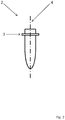
figure 1 montre une coupe d'un tel dispositif et le positionnement de deux préformes ; - la
figure 2 schématise une préforme à traiter, et - la
figure 3 montre une coupe le long de l'axe de rotation.
- the
figure 1 shows a section of such a device and the positioning of two preforms; - the
figure 2 schematizes a preform to be treated, and - the
figure 3 shows a section along the axis of rotation.
L'invention a donc tout d'abord comme objet un dispositif de convoyage 1 sélectif de produits 2 qui comprennent une collerette 3 saillante et présentent une symétrie de rotation autour d'un axe produit 4, ledit dispositif comprenant un moyen de convoyage 5 mobile entraînant les produits 2 depuis une zone de prise 6 jusqu'à une zone de sortie 7.The invention therefore firstly as a device for conveying 1
Ce dispositif de convoyage 1 est sélectif en ce sens que les produits 2 qu'il délivre en sortie sont tous orientés de la même façon, les uns à la suite des autres. Il fonctionne donc comme un dispositif qui déplace les produits 2 d'une zone de prise 6 à une zone de sortie 7, dans la mesure où ces produits 2 présentent une orientation prédéfinie, compatibles pour une alimentation de la machine en aval du dispositif de convoyage 1. Le moyen de convoyage 5 amène donc les produits 2, initialement en zone de prise 6, jusqu'à une zone de sortie 7, dans la mesure où les produits 2 présentent une orientation dans l'espace conforme et répétée d'un produit 2 à l'autre.This
Les produits 2 traités sont du type préforme 2 pour bouteille en plastique, ce qui signifie que leur collerette 3 est leur partie la plus saillante par rapport à leur axe produit 4. La collerette 3 sert, comme décrit plus loin, comme surface d'appui contre le moyen de convoyage 5, et, pour un produit 2 normalement engagé, s'étend dans le plan tangent à la trajectoire que suit le moyen de convoyage 5 le long de la boucle fermée.The treated
On notera que la zone de sortie 7 est munie d'au moins une embouchure dimensionnée pour le passage d'un seul produit 2 à la fois, dans le but de garantir un bon maintien en position des produits 2, lors de ce dégagement. Les couloirs qui s'étendent, chacun, à partir d'une embouchure, dimensionnés pour un seul produit 2 de front, peuvent éventuellement ensuite se rejoindre dans une jonction au niveau de laquelle les flux de chaque embouchure sont combinés en un seul flux.It will be noted that the
Selon l'invention, le moyen de convoyage 5 s'étend le long d'une boucle fermée définissant son mouvement le long d'une direction de convoyage 8 et présente une succession de butées transversales 9 d'entraînement des produits 2, ledit moyen de convoyage 5 étant ouvert de son côté intérieur 10 pour permettre la réception de produits 2 se trouvant à l'intérieur de ladite boucle. Comme il sera encore décrit plus loin, le moyen de convoyage 5 est ouvert du côté intérieur entre deux butées 9 successives, sous la forme de plusieurs entrefers successifs, où les produits 2 peuvent se loger. Les butées 9 forment des surfaces d'appui pour les collerettes 3 des produits 2 préformes. Ces surfaces d'appui se succèdent pour délimiter la partie intérieure du moyen de convoyage 5 par rapport à la partie extérieure. Ces entrefers sont donc plus larges que le corps des préformes 2 mais plus petits que les collerettes 3. Un des avantages d'une telle construction est qu'en ancrant mécaniquement les butées 9 dans des supports correspondants, l'entrefer entre elles est précis. En outre, la coopération se fait au niveau de la collerette 3, qui est un élément dont le dimensionnement change peu d'un type de produit 2 à l'autre.According to the invention, the conveying means 5 extends along a closed loop defining its movement along a conveying
Le moyen de convoyage 5 est préférablement sous forme de bande sans fin, fermée sur elle-même. Le moyen de convoyage 5 est donc mobile le long d'une boucle fermée qu'il suit. Le moyen de convoyage 5 présente ainsi un côté intérieur, du côté intérieur de la boucle fermée, et, à l'opposée, un côté extérieur. Les produits 2 sont saisis pas le moyen de convoyage 5 au niveau de son côté intérieur, grâce aux ouvertures créées entre deux butées 9 successives, et se trouvent donc initialement, en zone de prise 6, à l'intérieur de la boucle fermée.The
Le moyen de convoyage 5 suit donc une direction de convoyage 8, qui correspond, pour le point considéré, à la direction du mouvement duquel il est animé. A chaque point considéré, la direction de convoyage 8 s'étend donc sensiblement dans un plan tangent à la boucle fermée à ce point particulier. Comme il sera décrit, ce mouvement peut être circulaire. Le moyen de convoyage 5 a aussi une largeur, qui est perpendiculaire à la direction de convoyage 8, et le long de laquelle s'étendent des butées 9 transversales. Les butées transversales 9 sont donc perpendiculaires à l'avance du moyen de convoyage 5. Le moyen de convoyage 5 présente ainsi une succession de butées 9 transversales, qui forment une surface d'appui parallèle tant à la direction de convoyage 8 qu'à ladite largeur. Ces butées 9 sont espacées les unes des autres de façon régulière le long de la direction de convoyage 8.The conveying means 5 therefore follows a conveying
Ces butées 9 sont suffisamment éloignées l'une de l'autre pour laisser passer le corps d'un produit 2 mais non la collerette 3, de sorte que la partie d'extrémité des butées 9 du côté intérieur forme une surface d'appui pour les collerettes 3.These
Les butées 9 sont éloignées les unes des autres au moins au niveau de la circonférence intérieure du moyen de convoyage 5, ce qui permet aux produits 2, grâce aux ouvertures débouchantes ainsi créées, d'être reçus au sein du moyen de convoyage 5 dans les entrefers formés entre deux butées 9 successives. L'ancrage mécanique des butées 9 contribue notamment à une bonne précision de l'entrefer qui les sépare, et garantit ainsi que tout type de produit 2 soit correctement en appui sur elles.The
En zone de prise 6, la direction de convoyage 8 est sensiblement horizontale. Ainsi, un produit 2 préforme, avec une collerette 3 décalée axialement par rapport au centre de gravité de la préforme, s'il se trouve dans une position avec la tranche de la collerette 3 en appui sur les butées 9, peut pivoter en appui sur les butées 9 grâce à ce porte à faux et finalement aboutir en extension perpendiculaire tant à la direction de convoyage 8 qu'à la largeur du moyen de convoyage 5.In
Préférablement, la zone de prise 6 se trouve à l'intérieur de la boucle fermée, pour que les produits 2 puissent, sous l'effet de la pesanteur, se réorienter ou simplement s'engager dans les ouvertures du moyen de convoyage 5, côté intérieur. Comme les produits 2 sont du côté intérieur du moyen de convoyage 5, ceux mal engagés retombent dans la zone de prise 6, ce qui évite le recours à un moyen de recirculation forcée.Preferably, the
Le réglage de l'entrefer entre deux butées 9 successives peut se faire avec, pour chaque paire de butées 9 entre lesquelles se trouve un entrefer d'accueil, au moins l'une d'elle mobile par rapport à l'autre, voire les deux. Il est aussi envisageable qu'une butée 9 soit construite avec, d'une part, un support de structure, et, d'autre part, fixée de façon démontable sur ledit support, une pièce dont la dimension correspond à l'entrefer souhaité.The adjustment of the air gap between two
Selon une caractéristique additionnelle possible, le dispositif de convoyage 1 comprend, en outre, un moyen de blocage qui retient les produits 2 dans le moyen de convoyage 5. Le moyen de blocage permet d'éviter que les produits 2 pris dans le moyen de convoyage 5 et correctement engagés n'en retombent lorsqu'ils sont orientés tête en bas, et que la collerette 3 se trouve alors sous les butées 9. Le moyen de blocage peut être contrôlé, en ce sens que le passage entre un état actif, dans lequel il bloque les produits 2, et un état inactif, dans lequel il ne les retient pas, peut être piloté. Il peut aussi s'agir d'une simple peau en vis-à-vis des têtes des préformes 2 sur au moins une partie du parcours.According to an additional possible feature, the conveying
Ainsi, les produits 2 préformes peuvent facilement entrer dans le moyen de convoyage 5 entre deux butées 9 successives, le moyen de blocage n'empêchant pas cette insertion. Une fois que les produits 2 sont correctement engagés et insérés dans le moyen de convoyage 5, le moyen de blocage entre en fonctionnement et verrouille les produits 2 en position pour les maintenir correctement positionnés dans le moyen de convoyage 5Thus, the
Le moyen de blocage peut agir à n'importe quel endroit de la préforme 2 le long de son axe produit 4. Il peut saisir le produit 2 au niveau de son extrémité proche de la collerette 3, au niveau de la collerette 3 elle-même, au niveau de l'extrémité opposée, etc. L'avantage d'agir au niveau de l'extrémité ouverte, proche de la collerette 3, est que cette portion a des dimensions qui sont relativement les mêmes pour tous les produits 2 à traiter.The locking means may act at any point in the
Préférablement le moyen de blocage agit sur une portion du trajet entre la zone de prise 6 et la zone de sortie 7. Avantageusement, le moyen de blocage peut comprendre une contre plaque 11 qui agit au moins au niveau de la zone de sortie 7, pour garantir le positionnement des produits 2. Une telle contre plaque 11 peut être complétée par un moyen de serrage des produits 2 dans l'entrefer, du type à volet ou à guillotine, etc., qui est alors déverrouillé lorsque les produits 2 doivent être éjectés ou sortis.Preferably the blocking means acts on a portion of the path between the
Ainsi, selon une caractéristique additionnelle possible, le moyen de blocage comprend une plaque 11 située en vis-à-vis du moyen de convoyage 5, du côté intérieur de la boucle fermée, et s'étendant au moins le long d'une partie de ladite boucle. Cette plaque 11 suit la forme de la boucle fermée, du côté intérieur, à distance, et évite que les produits 2 ne retombent en zone de prise 6, leur éventuel dégagement radial des butées 9 les amenant contre cette plaque 11. Les produits 2 sont alors pris entre, d'une part, la plaque 11, et, d'autre part, les butées 9 contre lesquelles repose leur collerette 3.Thus, according to a possible additional feature, the locking means comprises a
Dans des réalisations possibles, le moyen de blocage comprend des volets 12, embarqués sur le moyen de convoyage 5 du côté extérieur de la boucle fermée et mobiles pour limiter l'espace entre deux butées 9 dans lequel les produits 2 s'étendent. Ces volets 12 sont mobiles en rotation et/ou en translation, pour limiter l'espace disponible aux produits 2 et ainsi les bloquer en position dans un état actif.In possible embodiments, the locking means comprises
Les volets 12 sont montés du côté extérieur ou du côté intérieur par rapport au profil circulaire défini par les surfaces d'appui des butées 9 successives. Ils peuvent donc venir contre les produits 2 à différents endroits le long de l'axe produit 2.The
Dans les cas utilisant tant une plaque 11 que des volets, la plaque 11 s'étendant préférablement au niveau de la zone de sortie 7 de sorte à éviter que les produits 2 ne se dégagent du moyen de convoyage 5 alors que les volets 12 n'agissent plus mais libèrent alors les produits 2.In the cases using both a
Selon une caractéristique additionnelle possible, les volets 12 sont déplacés sous l'effet de la gravité. En effet, comme ils sont montés sur les butées 9 qui circulent en boucle fermée autour d'un axe environ horizontal, les volets changent progressivement d'orientation par rapport à la verticale, ce qui permet d'utiliser leur propre poids pour les faire se déplacer vers une position de fermeture, ou vers une position d'ouverture. Ces volets 12 s'étendent parallèlement aux butées 9. Ils peuvent être montés grâce à des pions circulant dans des ouvertures oblongues correspondantes, le mouvement relatif étant provoqué par la mise en mouvement du moyen de convoyage 5 et le changement d'orientation conséquent.According to an additional possible feature, the
Selon une autre caractéristique additionnelle possible, les volets 12 sont déplacés par engagement mécanique avec une came fixe, en particulier fixe en rotation, et qui ne suit donc pas ce mouvement du moyen de convoyage 5. Cette came peut être réglable voire contrôlable pour faire passer les volets 12 d'un état à l'autre. Ainsi, il est par exemple envisageable de piloter cette came pour qu'elle change de position et ouvre alors les volets 12 lorsque le ou les produits 2 qu'ils maintiennent sont détectés au moins partiellement défectueux et passent par une zone de rejet 13. Cela permet d'utiliser l'état ouvert ou fermé des volets pour rejeter avant éjection des produits 2 éventuellement non tous conformes le long d'une paire de butées 9.According to another possible additional characteristic, the
Ainsi, selon une caractéristique additionnelle possible, le moyen de blocage est piloté pour libérer, le cas échéant, les produits 2 au niveau d'une zone de rejet 13 se trouvant avant la zone de sortie 7 et à partir de laquelle ils peuvent alors quitter le moyen de convoyage 5, et retomber notamment en zone de prise 6 en cas de non-conformité d'orientation ou être expulsés du dispositif de convoyage 1 en cas de non-conformité structurelle des produits 2.Thus, according to an additional possible feature, the blocking means is controlled to release, where appropriate, the
Le dispositif de convoyage 1 comprend notamment, en outre, d'une part, un moyen de vérification des produits 2 dans une zone amont à la zone de rejet 13, et, d'autre part, une unité de pilotage reliée au moyen de contrôle et qui actionne le moyen de blocage en cas de détection d'une anomalie.The conveying
Selon une autre caractéristique additionnelle possible du dispositif de convoyage 1, il comprend, en outre, un dispositif d'éjection qui agit en zone de sortie 7 pour pousser les produits 2 le long des butées 9 transversales et les éjecter du moyen de convoyage 5 transversalement à la direction de convoyage 8. Comme il a déjà été précisé, la zone de sortie 7 présente une embouchure, voire plusieurs, chacune étant dédiée à un canal de circulation en aval, dimensionné pour un seul produit 2 de front.According to another possible additional feature of the conveying
Le dispositif d'éjection agit alors par poussée mécanique depuis le côté du moyen de convoyage 5 qui est opposé à celui où se trouve la zone de sortie 7, et agit sur l'ensemble des produits 2 qui se trouvent entre une paire de butées 9 pour les pousser vers l'embouchure.The ejection device then acts by mechanical pushing from the side of the conveying
Dans certaines réalisations possibles, le moyen de convoyage 5 prend la forme d'un tambour cylindrique creux présentant une symétrie de rotation autour d'un axe de tambour 14 s'étendant sensiblement horizontalement, les butées transversales 9 s'étendant le long de génératrices et étant maintenues espacées les unes des autres par une paire de flasques 15 auxquelles elles sont fixées par leurs extrémités, ledit tambour étant mobile en rotation autour de l'axe de tambour 14.In some possible embodiments, the conveying
La zone de prise 6 se trouve notamment au coeur du tambour, en partie inférieure, la zone de sortie 7 se trouve notamment en partie haute ou encore sur un côté, par exemple après une rotation de trois quarts de tour, la zone de rejet 13 se trouvant notamment au-dessus de la zone de prise 6, en amont de la zone de sortie 7.The gripping
Les butées 9 sous forme de poutrelles peuvent être montées dans une flasque 15 avec possibilité de déplacement par exemple radial, par exemple avec une ouverture oblongue, ce qui permet alors d'ajuster par réglage l'écartement entre deux butées 9 successives, et donc la taille de l'entrefer qui doit accueillir le corps des préformes 2. Dans l'absolu, seule l'une des butées 9 définissant l'entrefer peut être avec possibilité de réglage dans les flasques 15, l'autre n'ayant qu'une seule position de montage.The
Un tel déplacement de butées 9 qui n'ont pas de fonction structurelle essentielle peut par exemple être effectué par un actionneur, du type moteur électrique avec jeu d'engrenage et/ou bielles, cardans, etc.Such displacement of
Il est aussi envisageable de monter des butées 9 qui sont dédiées au support des produits 2 et qui n'ont pas de fonction structurelle dans le moyen de convoyage 5 en tambour, cette fonction étant assurée par des poutrelles de structure dédiées à cela, et n'ayant alors, quant à elles, pas d'interaction prévue avec les produits 2. Le réglage des butées 9 en position, et donc le réglage de l'entrefer entre elles est davantage simplifié.It is also conceivable to mount
L'invention a aussi pour objet un procédé mettant en oeuvre le dispositif tel que décrit ci-dessus, à savoir un procédé de convoyage de produits 2 qui ont une forme cylindrique et qui présentent, d'une part, une symétrie de rotation autour d'un axe produit 4, et, d'autre part, une collerette 3 circonférentielle saillante, ledit procédé comprenant, d'une part, une étape consistant essentiellement à élever les produits 2 au cours de leur déplacement, depuis une zone de prise 6 où les produits 2 se trouvent en vrac, jusqu'à une zone de sortie 7, et ce à l'aide d'un moyen de convoyage 5 mobile formant une boucle fermée, et, d'autre part, une étape consistant essentiellement à éjecter les produits 2 au niveau de la zone de sortie 7.The subject of the invention is also a method implementing the device as described above, namely a method of conveying
Les produits 2 éjectés en zone de sortie 7 sont tous orientés de la même manière, et l'intérêt de l'élévation sur le trajet entre la zone de prise 6 et la zone de sortie 7 est de contribuer à éliminer les produits 2 qui ne présenteront pas l'orientation souhaitée dans la zone de sortie 7.The
Les produits 2 qui arrivent en zone de sortie 7 sont donc normalement tous conformes, et tous les produits 2 qui y arrivent sont alors éjectés.The
Selon l'invention, l'élévation est sélective, le moyen de convoyage 5 entraînant les produits 2 situés à l'intérieur de la boucle fermée, orientés avec leur axe produit 4 traversant le moyen de convoyage 5 du côté intérieur vers le côté extérieur, notamment essentiellement perpendiculaire à ladite boucle fermée.According to the invention, the elevation is selective, the conveying
Le moyen de convoyage 5 n'entraîne donc pas les produits 2 qui s'étendent parallèlement à l'axe fixe autour duquel il circule, mais il n'amène jusqu'en zone de sortie 7 que les produits 2 qui s'étendent avec un axe produit 4 qui traverse la boucle fermée. Une extrémité d'un tel produit 2 va donc vers le côté intérieur du moyen de convoyage 5, alors que l'autre extrémité va vers le côté extérieur. Les produits 2 non entraînés jusqu'en zone de sortie 7 retombent en zone de prise 6. Plus précisément, les produits 2 orientés de cette manière avec en outre leur plus petite partie depuis la collerette 3 dirigée vers l'extérieur de la boucle fermée, et leur plus grande partie dirigée vers l'intérieur, sont eux aussi renvoyés en zone de prise 6.The conveying means 5 does not therefore cause the
Les produits 2 s'engagent donc dans le moyen de convoyage 5 depuis le côté intérieur jusqu'à ce que leur collerette 3 vienne en appui sur des butées 9. La partie des produits 2 en appui dans le moyen de convoyage 5 se trouve donc du côté intérieur de la boucle fermée qu'il suit. Comme il sera encore décrit plus loin, une telle configuration facilite l'insertion des produits 2, mais aussi leur chute vers la zone de prise 6 en cas de non-conformité. L'avantage de retomber en zone de prise 6 en cas de mauvaise orientation est qu'il n'est alors pas nécessaire d'intégrer un appareil de recirculation des préformes éjectées pour défaut d'orientation.The
L'élévation est donc sélective en ce sens que c'est lorsque les produits 2 sont élevés que ceux qui ne sont pas correctement engagés ont tendance à quitter le moyen de convoyage 5, et ce grâce au changement d'orientation par rapport à la pesanteur que subit pendant cette élévation la surface d'appui sur laquelle vient la collerette 3 et qui est portée par les butées 9, ce changement d'orientation étant provoqué par la configuration en boucle fermée.Elevation is therefore selective in that it is when
Selon une caractéristique additionnelle possible du procédé, il comprend une étape consistant essentiellement à bloquer en position les produits 2 entraînés par le moyen de convoyage 5, en particulier uniquement ceux correctement engagés contre les butées 9. Ce blocage évite alors aux produits 2 de se dégager des butées 9, notamment par un mouvement le long de leur axe produit 4, qui aurait tendance à faire se décoller la collerette 3 des butées 9.According to a possible additional feature of the method, it comprises a step consisting essentially of blocking in position the
Selon une autre caractéristique additionnelle possible, en cas de non-conformité, les produits 2 sont relâchés, avant leur passage par la zone de sortie 7, lorsqu'ils passent par une zone de rejet 13, notamment une zone de rejet 13 située en hauteur pour provoquer une chute des produits 2. La non-conformité peut être une non-conformité d'orientation dans le moyen de convoyage, ou encore un défaut structurel intrinsèque du ou des produits 2.According to another possible additional characteristic, in the event of non-conformity, the
Selon une caractéristique additionnelle possible du procédé, il comprend une étape d'éjection, au cours de laquelle les produits 2, dans la zone de sortie 7, sont dégagés du moyen de convoyage 5 transversalement au mouvement de ce dernier, le moyen de convoyage 5 comprenant notamment une succession de butées transversales 9 espacées, accueillant entre deux telles butées 9 une rangée de produits 2, les produits 2 étant éjectés une rangée après l'autre, l'éjection créant ainsi un flux de sortie de produits 2 large d'un seul produit 2. Bien entendu, les produits 2 sont normalement débloqués avant leur éjection.According to a possible additional feature of the method, it comprises an ejection step, during which the
Après cette éjection, les produits 2 sont délivrés par le dispositif de convoyage 1. Les produits 2 éjectés à ce stade présentent donc tous la même orientation, les uns derrière les autres.After this ejection, the
Enfin, dans des modes de réalisation possibles, entre la zone de prise 6 et la zone de sortie 7, le moyen de convoyage 5 fait passer les produits 2 par au moins une zone de traitement située sur le trajet des produits 2 entre lesdites zones, tel qu'une ionisation ou une séparation de produits 2 emboîtés l'un dans l'autre. Un des avantages de disposer diverses zones de traitement au fil du trajet des produits 2 sous l'effet du moyen de convoyage 5 est bien entendu qu'une même architecture peut alors être utilisée pour l'exécution de différents processus de traitement sur les produits 2, comme par exemple aussi une détection optique, et ce sans augmenter le gabarit du dispositif de convoyage 1 puisque ces appareils peuvent se trouver à l'intérieur de la boucle fermée.Finally, in possible embodiments, between the gripping
Dans le mode de réalisation illustré aux figures annexées, le dispositif de convoyage 1 se présente essentiellement sous la forme d'un tambour rotatif, au coeur duquel les produits 2 préformes sont déposées en partie inférieure.In the embodiment illustrated in the accompanying figures, the conveying
Ce dispositif de convoyage 1 est donc destiné à alimenter en préformes une machine en aval, ayant une fonction de soufflage. Ces préformes sont chauffées et étirées jusqu'à obtenir la forme finale du contenant. Le dispositif de convoyage 1 sert à fournir à une telle machine des produits 2 sous forme de préformes qui ont toutes la même orientation dans l'espace. Le dispositif de convoyage 1 génère donc un flux de préformes formant produits 2 qui représente une colonne large d'un tel produit 2. Les préformes sont initialement déposées sous forme d'un vrac, et donc d'un ensemble de produits 2 dont l'orientation n'est pas maîtrisée. Dans cet amas les préformes ont une orientation quelconque et l'une des fonctions du dispositif de convoyage 1 est alors de transformer un tel ensemble de produits 2 d'agencement libre en une colonne unifilaire de produits 2 tous orientés de la même manière.This conveying
Pour ce faire, le dispositif de convoyage 1 est muni d'un tambour creux tournant. La paroi périphérique de ce tambour est formée par un moyen de convoyage 5, qui est donc agencé en boucle fermée. Ce moyen de convoyage 5 suit une boucle fermée dans un plan vertical de sorte que les préformes qu'il entraîne sont au moins temporairement élevées. C'est au cours de cette élévation que seules les préformes correctement orientées sont entraînées par le moyen de convoyage 5, alors que celles ayant une orientation différente ne sont pas entraînées vers le haut par le moyen de convoyage 5. Ce convoyage sélectif en fonction de l'orientation des préformes contribue à assurer que le dispositif de convoyage 1 fournit bien des préformes toujours orientées de la même manière.To do this, the conveying
Plus précisément, le moyen de convoyage 5, qui définit la circonférence du tambour du dispositif de convoyage 1, se présente sous la forme d'une succession de butées transversales 9 qui permettent d'engager et d'entraîner les préformes.More precisely, the conveying
Le moyen de convoyage 5 forme ainsi un profil circulaire autour d'un axe de tambour 14, qui est normalement horizontal. Le moyen de convoyage 5 se déplace en suivant une rotation autour de cet axe de tambour 14, définissant ainsi une direction de convoyage 8 le long de laquelle il entraîne avec lui les préformes qu'il engage. L'axe de tambour 14 est donc perpendiculaire à la direction de convoyage 8.The conveying means 5 thus forms a circular profile around a
La dimension du tambour le long de l'axe de tambour 14, c'est-à-dire sa largeur, impacte le nombre maximum de préformes que le dispositif de convoyage 1 peut emporter le long d'une butée transversale 9.The dimension of the drum along the
Les butées 9 s'étendent parallèlement à l'axe de tambour 14 et sont les unes à côté des autres le long de la direction de convoyage 8. Les butées 9 sont décalées les unes des autres pour que des préformes puissent être reçues entre deux butées 9 successives. Une paire de butées 9 adjacentes définit donc un entrefer dans lequel les préformes peuvent s'insérer.The
Les préformes présentent une forme de cylindre avec symétrie de rotation autour d'un axe produit 4. Une préforme présente ainsi un corps, à partir duquel s'étend, en saillie, une collerette 3 circonférentielle. La collerette 3 représente la zone de la préforme la plus éloignée de l'axe produit 4. La préforme a deux extrémités opposées le long de l'axe produit 4 : l'une d'elle, ouverte, formera le buvant du contenant final et est généralement pourvue d'un filetage pour coopérer avec un bouchon à visser, l'autre extrémité, fermée, à l'opposée, formera le fond du contenant final. La collerette 3 est plus proche de l'extrémité ouverte, avec une dimension similaire à la hauteur d'un bouchon, que de l'extrémité fermée.The preforms have a cylinder shape with symmetry of rotation about a
Deux butées 9 successives du moyen de convoyage 5 sont alors éloignées le long de la direction de convoyage 8, perpendiculairement à l'axe de tambour 14, d'une distance qui est supérieure au diamètre du corps des préformes, ce diamètre étant en tout point plus faible que le diamètre de la collerette 3. Cet entrefer est cependant plus petit que le diamètre de la collerette 3. Ainsi, le corps d'une préforme 2 peut s'insérer entre deux butées 9, et le mouvement d'insertion sera stoppée lorsque la collerette 3 viendra en appui contre les butées 9.Two
Le moyen de convoyage 5 emmène donc, depuis la zone de prise 6 où elles sont en vrac, les préformes 2 qui sont insérées entre deux butées 9 successives, reposant sur ces butées 9 avec leur collerette 3. Compte tenu du trajet d'élévation qui suit la zone de prise 6, les préformes 2 mal orientées dans le moyen de convoyage 5, qui les entraîne sans pour autant qu'elles soient réellement engagées comme décrit plus haut, retombent le long du moyen de convoyage 5 et retournent en zone de prise 6.The conveyor means 5 thus takes, from the gripping
Ces préformes 2 mal orientées sont notamment celles dont l'axe produit 4 s'étend le long de l'axe de tambour 14 et qui reposent donc sur les butées 9 parallèlement à elles. De la même manière, les préformes 2 qui sont orientées vers l'intérieur avec leur axe produit 4 le long d'un rayon du moyen de convoyage 5, ce dernier étant circulaire autour de l'axe de tambour 14, retombent sous l'effet de la gravité. En effet, ces préformes 2 ont une partie en porte à faux significative, à savoir celle entre la collerette 3 et l'extrémité de fond de la préforme 2, alors que la partie complémentaire de la préforme, entre la collerette 3 et l'extrémité ouverte, est engagée entre deux butées 9 et ne peut pas empêcher le basculement de la préforme 2 sous l'effet de son poids lors de l'élévation et pivotement associé. L'espace entre deux butées 9 successives est donc légèrement plus grand que le diamètre du corps de la préforme 2, pour permettre un jeu suffisant menant à la chute de la préforme, le cas échéant.These poorly oriented preforms 2 are in particular those whose
Ainsi, grâce à l'élévation des préformes 2 qu'il provoque, le moyen de convoyage 5 n'entraîne normalement vers la zone de sortie 7 que les préformes 2 qui sont engagées entre deux butées 9 avec leur axe produit 4 le long d'un rayon, perpendiculaire à l'axe de tambour 14, et donc perpendiculaire à la boucle fermée que suit le moyen de convoyage 5, orientées de sorte que l'extrémité ouverte de la préforme 2 se trouve, par rapport à l'extrémité fermée, du côté intérieur du moyen de convoyage 5 et donc de la boucle fermée qu'il suit.Thus, by virtue of the elevation of the
Les préformes 2 s'engagent donc dans le moyen de convoyage 5 depuis l'intérieur de ce dernier. Les préformes 2 se trouvent initialement à l'intérieur du moyen de convoyage 5 et s'insèrent entre deux butées 9 pour un engagement et un entraînement par le moyen de convoyage 5 en se dirigeant vers la périphérie extérieure du moyen de convoyage 5, s'arrêtant dans ce mouvement dès que les collerettes 3 arrivent contre les butées 9.The
La zone de prise 6 se trouve ainsi en partie basse du cylindre creux définissant la boucle fermée que suit le moyen de convoyage 5 dans son mouvement. En zone de prise 6, les préformes 2 se trouvent alors en vrac au-dessus du moyen de convoyage 5 qui se déplace sous elles. C'est donc la gravité qui a tendance à faire bouger les préformes 2 pour qu'elles s'insèrent entre deux butées 9 avec leur axe produit 4 le long d'un rayon. On notera que la pesanteur peut avoir pour effet de faire pivoter la préforme dont la collerette 3 est en appui sur les butées 9 mais pas encore correctement alignées le long d'un rayon.The gripping
Les préformes 2 s'engagent donc dans le moyen de convoyage 5 depuis son côté intérieur avec un mouvement d'insertion depuis l'intérieur vers l'extérieur. Plusieurs préformes 2 s'engagent entre deux butées 9 successives. Ainsi, entre deux butées 9 successives, le moyen de convoyage 5 entraîne une pluralité de préformes 2 sous forme de lot, les produits 2 préformes étant alignées dans l'entrefer séparant deux butées 9 et donc alignés le long de l'axe de tambour 14. On comprend qu'il peut exister un écart entre deux produits 2 successifs dans la direction de l'axe de tambour 14, puisque les produits 2 s'insèrent dans le moyen de convoyage 5 à partir de leur position initiale en zone de prise 6, qui peut être variée le long de l'axe de tambour 14. Le vrac peut en effet s'étendre sur toute la largeur du moyen de convoyage 5, c'est-à-dire sa dimension intérieure le long de l'axe de tambour 14, ce dernier étant par ailleurs préférablement sensiblement horizontal.The
Les préformes correctement engagées dans le moyen de convoyage 5 suivent ensuite son mouvement de rotation circulaire autour de l'axe de tambour 14, jusqu'à une zone de sortie 7. Comme le moyen de convoyage 5 a un mouvement circulaire et que la zone de prise 6 est en partie basse de ce cercle, la zone de sortie 7 est généralement plus haute que la zone de prise 6.The preforms properly engaged in the conveying
En zone de sortie 7, les préformes 2 sont dégagées pour être alimentées à la machine en aval. Cette sortie se fait en poussant les préformes 2 parallèlement à l'axe de tambour 14 pour qu'elles passent par une embouchure de dimension adaptée. En aval de cette embouchure, les préformes 2 continuent leur circulation dans un canal de dimensions adaptées, sous forme d'un flux monocolonne, c'est-à-dire large d'un seul produit 2, les préformes étant l'une derrière l'autre.In
Le dispositif de convoyage 1 fait passer l'une après l'autre à travers cette embouchure les préformes 2 qui formeront le flux de sortie. Afin d'éviter les risques de coincement, la circulation à travers cette embouchure se fait avec une seule préforme 2 à la fois, de sorte qu'il n'est pas nécessaire d'organiser une convergence de plusieurs flux parallèles. L'embouchure a une dimension adaptée et une géométrie correspondante aux préformes 2, puisqu'il reste nécessaire de les y maintenir en position lors de l'évacuation.The conveying
Il est bien entendu envisageable d'aménager plusieurs telles embouchures. Dans ce cas, une colonne large d'un seul produit 2 passe par chaque embouchure, et les colonnes sont ensuite mises l'une derrière l'autre en aval, pour former une seule et même colonne.It is of course conceivable to arrange several such mouths. In this case, a wide column of a
Ainsi, les préformes 2 sont dégagées du moyen de convoyage 5 de la façon suivante. L'ensemble des préformes 2 qui se trouvent dans l'entrefer créé par une même paire de butées 9 est poussé transversalement, le long de l'axe de tambour 14, lorsqu'elles sont en vis-à-vis de la zone de sortie 7. Une fois cet entrefer vidé, le suivant est traité et les préformes 2 qui sont engagées dans cet entrefer sont donc à leur tour poussées à travers l'embouchure de la zone de sortie 7. Le lot formé par l'ensemble des préformes qui se trouvent prises dans l'entrefer entre deux butées 9 successives est donc dégagé une fois que le lot précédent a été entièrement dégagé.Thus, the
Grâce à son mouvement de rotation continu, le moyen de convoyage 5 amène en permanence en vis-à-vis de la zone de sortie 7 un nouvel entrefer et donc l'ensemble des préformes 2 qu'il contient et qui sont engagées dans cet entrefer.Due to its continuous rotational movement, the conveying
L'embouchure en zone de sortie 7 est dimensionnée pour une colonne large d'un seul produit 2, et le contenu d'un seul entrefer est dégagé simultanément. Ainsi, à chaque instant, une colonne ou rangée large d'un seul produit 2 passe par la zone de sortie 7 ce qui évite l'agencement d'une zone de convergence de plusieurs flux parallèles devant aboutir à un flux monocolonne en sortie de dispositif de convoyage 1, et les risques de coincement associés à une telle convergence.The mouth in
Le moyen de convoyage 5 prend préférablement la forme d'un tambour rotatif circulaire autour de son axe de symétrie, à savoir l'axe de tambour 14. Ce tambour est défini par des butées 9 successives, maintenues à leurs extrémités dans des flasques 15 planes, disposées perpendiculairement à l'axe de tambour 14. Les préformes 2 sont préférablement alimentées à l'intérieur de la boucle fermée que suit le moyen de convoyage 5 depuis un côté du moyen de convoyage 5, à savoir depuis une extrémité le long de l'axe de tambour 14. La flasque 15 correspondante est donc évidée et prend la forme d'une couronne pour fournir un accès à l'intérieur du tambour. La zone de sortie 7 est aménagée à une extrémité axiale du moyen de convoyage 5, préférablement l'extrémité opposée à celle d'où les produits 2 sont amenées au coeur du tambour. La flasque 15 correspondante est munie de passages dimensionnés pour que les préformes puissent circuler à travers elle au niveau de ces passages et rejoindre l'embouchure de la zone de sortie 7.The conveying means 5 preferably takes the form of a circular rotating drum about its axis of symmetry, namely the
Préférablement, les préformes 2 sont dégagées transversalement vers la zone de sortie 7 grâce à un poussoir qui se déplace essentiellement le long de l'axe de tambour 14, en face de la zone de sortie 7. Ce poussoir agit donc contre la préforme la plus éloignée de la zone de sortie 7 le long de la butée 9 et la pousse vers la suivante et ainsi de suite jusqu'à ce que toutes les préformes 2 alignées soient aussi compactées, les unes contre les autres, au moment du passage en zone de sortie 7. L'embouchure de la zone de sortie 7 voit donc circuler des trains compacts de préformes 2, dans lesquels elles sont les unes contre les autres, sous l'effet de l'action d'un poussoir sur la première d'entre elles.Preferably, the
Le poussoir agit à proximité de la collerette 3 plutôt qu'au niveau de l'extrémité de fond du produit 2, afin d'éviter que les produits 2 ne s'arcboutent et se bloquent, la collerette 3 formant point d'appui pour une rotation en cas de poussée mécanique trop éloignée d'elle. Le poussoir peut agir du côté extérieur ou du côté intérieur par rapport au moyen de convoyage 5, la frontière entre le côté extérieur et le côté intérieur étant éventuellement définie par la succession des surfaces de butées sur lesquelles les collerettes 3 peuvent venir.The pusher acts near the
Comme expliqué plus haut, les préformes 2 s'engagent dans le moyen de convoyage 5 depuis une zone de prise 6 située à l'intérieur de la boucle fermée qu'il forme. Une fois correctement engagée, et donc dans une orientation prédéfinie pour une fourniture de préformes 2 toujours orientées de la même façon, les préformes 2 arrivent en zone de sortie 7. Les surfaces d'appui que forment les butées 9 sont essentiellement horizontales en zone de prise 6 et, sous l'effet du déplacement du moyen de convoyage 5 le long d'une boucle fermée circulaire, elles changent peu à peu d'orientation jusqu'à devenir verticale. Ce changement d'orientation des surfaces d'appui permet en particulier de faire retomber les préformes 2 qui ne sont pas correctement engagées dans l'entrefer et donc de ne convoyer plus en aval que les préformes qui sont effectivement engagées avec leur corps dans l'entrefer entre deux butées 9.As explained above, the
En zone de prise 6, les surfaces d'appui se trouvent donc normalement dans la partie haute des butées 9. Compte tenu du mouvement en boucle fermée, on comprend qu'au cours du cycle de déplacement, les surfaces d'appui se trouvent au moins temporairement en partie basse des butées 9. Autrement dit, en zone de prise 6, les collerettes 3 arrivent au-dessus des butées 9, alors qu'elles se retrouvent à un moment du cycle, au-dessous des butées 9, et les préformes 2 ne reposent alors plus sur ces supports 9 pour compenser la gravité.In gripping
En fonction de la localisation de la zone de sortie 7 sur le trajet des préformes 2 depuis la zone de prise 6, il peut donc être nécessaire de prévoir une solution du type moyen de blocage pour éviter la chute des préformes, ne reposant alors plus sur les butées 9.Depending on the location of the
Ainsi, un contre guide peut être prévu en vis-à-vis du moyen de convoyage 5 au moins pour la partie où le profil du circuit fermé fait que les préformes 2 ne reposent plus sur les butées 9. Ce contre guide peut prendre la forme d'une plaque 11 qui épouse la géométrie du trajet du moyen de convoyage 5 à cet endroit. Par exemple, il peut s'agir d'une plaque 11 présentant une base sous forme d'arc de cercle, s'étendant parallèlement à l'axe de tambour 14.Thus, a counter-guide may be provided opposite the conveying
Cette plaque 11 se trouve à distance des surfaces de contact que forment les butées 9. Cette distance est légèrement supérieure à la longueur de la préforme entre la collerette 3 et l'extrémité ouverte. Cette plaque 11 évite que les préformes 2 ne se retirent de l'entrefer et crée une zone d'accueil jusqu'aux surfaces d'appui que portent les butées 9.This
Les préformes 2 peuvent être retenues dans le moyen de convoyage 5 grâce à une solution de verrouillage qui agit au niveau de la tête des produits 2, c'est-à-dire de leur extrémité proche de la collerette 3, ce qui présente l'avantage d'une coopération mécanique avec une portion des préformes 2 dont le dimensionnement change peu en fonction des produits 2, ce qui assure une certaine flexibilité et adaptabilité du dispositif de convoyage 1.The
Il est aussi envisageable de retenir les préformes dans les entrefers en les resserrant au moment opportun, par exemple avec un volet 12 qui vient plaquer les préformes 2 contre l'une des butées 9. Dans certains cas particuliers, les butées 9 forment un entrefer qui est moins profond que la longueur des préformes entre leur collerette 3 et leur extrémité de fond. Dans ces cas, les préformes 2 dépassent du fond des butées 9. Il est alors possible de prévoir, au niveau du fond d'une des deux butées 9 formant une paire définissant un entrefer dans lequel les préformes 2 sont reçues, un volet 12 qui se déplace contre ce fond. Ce volet 12 forme pour l'essentiel une paroi qui s'étend le long de l'axe de tambour 14 et contre le fond de la butée 9, c'est-à-dire contre la surface périphérique extérieure de la butée 9.It is also conceivable to hold the preforms in the air gaps by tightening them at the appropriate moment, for example with a
Dans une première position de ce volet 12, ou position escamotée, le volet 12 ne s'étend pas en vis-à-vis de l'entrefer et est donc entièrement contre la butée 9. Dans une deuxième position, il s'étend en vis-à-vis de cet entrefer et l'obture donc au moins partiellement. Ainsi, dans cette position, le volet 12 vient contre une préforme 2 qui déborde des butées 9 vers l'extérieur. Il forme alors une guillotine qui plaque la préforme 2 contre la butée 9 sur laquelle ledit volet 12 n'est pas monté.In a first position of this
Préférablement, chaque paire de butée 9 présente alors un tel volet 12, qui a pour fonction de retenir dans l'entrefer les préformes 2 qui y sont engagées.Preferably, each pair of
Ces volets 12 peuvent donc passer d'une position active, où ils serrent les préformes 2 dans l'entrefer, à une position inactive, où ils n'agissent pas sur les préformes 2. On comprend que les préformes 2 doivent pouvoir facilement s'engager entre les butées 9 notamment en zone de prise 6 et que les volets 12 doivent alors se trouver en position inactive. Lorsque les butées 9 sont au-dessus des collerettes 3, il faut que les volets 12 soient en position active. Lorsque les préformes 2 sont en zone de sortie 7, les volets 12 doivent permettre le mouvement des préformes 2 et donc se trouver en position inactive. Le passage d'une position à l'autre peut se faire sous l'effet de la gravité par exemple, puisque le poids du volet 12 lui-même peut l'attirer vers l'autre butée 9 à certains endroits et aux orientations correspondantes, alors qu'il l'en éloignera à d'autres endroits et orientations correspondantes.These
Alternativement, un mécanisme actif peut être prévu, qui vient agir sur les volets 12 pour les déplacer et les faire passer d'une position l'autre. Un tel mécanisme peut par exemple utiliser un principe de cames fixes, contre lesquelles viennent les volets 12 au cours de leur circulation et qui les font passer d'une position à l'autre et inversement.Alternatively, an active mechanism may be provided, which acts on the
La combinaison d'un jeu de volets 12 et d'une plaque 11 formant contre guide est bien sûr envisageable.The combination of a set of
En outre, les volets 12 peuvent être coulissants ou pivotants avec le même effet.In addition, the
Dans certaines réalisations avantageuses, le dispositif de convoyage 1 est muni d'un moyen de contrôle des préformes 2 avant fourniture en zone de sortie 7. Un tel moyen de contrôle est préférablement basé sur un principe de vision et scanne une zone fixe dans laquelle le moyen de convoyage 5 fait passer successivement les préformes 2 maintenues entre deux butées 9 successives. Cette zone de détection se trouve en amont de la zone de sortie 7. En cas de détection d'un défaut dans le lot de préformes 2 engagés dans une paire de butées 9, il est alors envisageable d'éjecter l'ensemble de ce lot. En cas de défaut majeur, cette éjection peut amener les préformes 2 à être dégagées et traitées comme des rebuts. S'il s'agit d'un simple défaut d'orientation, les préformes 2 peuvent alors simplement relâchées depuis une zone au-dessus de la zone de prise 6, ce qui a pour effet de les faire retomber en zone de prise 6.In certain advantageous embodiments, the conveying
Dans ces cas, les préformes 2 détectées comme mal orientées sont simplement lâchées par le moyen de verrouillage précités, du type à volets 12 et/ou à contre plaque 11, pour un recyclage.In these cases, the
Le dispositif de convoyage 1 est alors muni d'une unité de détection, qui est préférablement placée à l'intérieur du moyen de convoyage 5, et détecte en amont de la zone de sortie 7. Le dispositif de convoyage 1 est aussi muni d'un moyen de blocage contrôlé des préformes 2 bloquant ces dernières dans le moyen de convoyage 5, ainsi que d'une unité de contrôle, qui reçoit le signal de l'unité de détection et pilote le moyen de blocage contrôlé pour relâcher le lot de produits 2 détecté comme comprenant un produit 2 non satisfaisant.The conveying
Les préformes 2 subissent donc un mouvement, créé par le moyen de convoyage 5 qui engage celles bien orientées, entre une zone de prise 6, où le moyen de convoyage 5 évolue sous les préformes 2, et une zone de sortie 7 où les préformes 2 sont dégagées dans un mouvement le long de l'axe de tambour 14. Ce mouvement suit la boucle fermée le long de laquelle se déplace le moyen de convoyage 5. Dans certaines réalisations avantageuses, le dispositif de convoyage 1 est muni de divers équipements répartis sur le trajet des préformes et qui les traitent successivement au cours de ce trajet. La zone de sortie 7 peut se trouver à divers endroits après l'élévation et changement d'orientation des butées 9, notamment dans une partie supérieure, diamétralement opposée à la zone de prise 6, ou encore sur un côté, après une rotation de trois quarts de tour du moyen de convoyage 5 depuis la zone de prise 6.The
De tels équipement sont préférablement disposés à l'intérieur du tambour ou de la boucle fermée que forme le moyen de convoyage 1 et agissent sur les produits 2 dans une zone de traitement qui leur est propre, le cas échéant. Ainsi, le dispositif de convoyage 1 peut être muni d'un ioniseur, qui traite les rangées successives de produits 2 qui défilent devant lui. Le dispositif de convoyage 1 peut aussi être muni d'un démêleur, sous forme de brosse rotative qui se trouve en vis-à-vis du moyen de convoyage 5 et qui fait sortir les préformes 2 enchâssées dans une autre préforme 2, qui est, elle, correctement orientée et maintenue entre les butées 9. Des solutions à base de lames flexibles sont aussi envisageables.Such equipment is preferably arranged inside the drum or the closed loop formed by the conveying
Préférablement, le dispositif de convoyage 1 est aussi muni d'un convoyeur d'entrée, du type convoyeur à bande sans fin. Ce convoyeur s'étend essentiellement horizontalement pour amener des préformes 2 à l'intérieur du moyen de convoyage 5, c'est-à-dire pour les déposer dans la zone de prise 6. Ce convoyeur d'entrée reçoit les préformes 2 en vrac sur sa surface supérieure et s'étend jusqu'à l'intérieur de la boucle fermée que forme le moyen de convoyage 5. Les produits 2 tombent alors du convoyeur d'entrée dans le moyen de convoyage 5.Preferably, the conveying
Ainsi, dans les configurations selon l'invention, avec une zone de prise 6 en bas, les préformes 2 mal orientées retournent directement en zone de prise 6 pour être éventuellement traitées plus tard, ce qui aboutit à un fonctionnement en boucle fermée. Directement après la zone de prise 6, le moyen de convoyage 5 assure une élévation et un pivotement des préformes 2 jusqu'à environ une position horizontale, de sorte que seules celles bien orientées, et donc bien engagées, sont amenées plus loin par lui. Les autres, qui ne sont pas correctement maintenues, retombent en zone de prise 6 jusqu'à être finalement correctement orientées et entraînées.Thus, in the configurations according to the invention, with a gripping
Grâce à la configuration en boucle fermée à l'intérieur de laquelle les produits 2 sont disposés et engagés par le moyen de convoyage 5, le moyen de convoyage 5 se trouve initialement sous les produits 2, pour leur engagement, puis horizontalement à côté d'eux, puis se trouve au-dessus d'eux, préférablement au droit de la zone de prise 6.Thanks to the closed-loop configuration in which the
L'avantage est alors qu'une fois le moyen de convoyage 5 au-dessus des préformes 2, celles qui sont mal orientées et qui auraient été entraînées malgré tout ne résistent pas à la force créée par leur poids et retombent verticalement en zone de prise 6. Cela contribue donc à assurer qu'un produit 2 mal orienté n'arrive pas en zone de sortie 7 mais est renvoyé en zone de prise 6. Changer progressivement l'orientation des préformes 2 par rapport à l'horizontal jusqu'à les mettre tête en bas, grâce à un changement progressif d'orientation des butées 9 le long de la boucle fermée, permet alors d'assurer que seules les préformes 2 correctement engagées et retenues dans le moyen de convoyage 5 arrivent finalement en zone de sortie 7. Prévoir un moyen de convoyage 5 en boucle fermée, à l'intérieur de laquelle se trouve le vrac de produits 2, aboutit à une configuration simple du moyen de convoyage 5.The advantage is that once the conveying
Le moyen de convoyage 5 circule donc le long de la boucle fermée pour que ses butées 9 forment des surfaces d'appui qui se trouvent initialement sous les produits 2 en zone de prise 6 puis, après rotation progressive, au-dessus des produits 2.The conveying means 5 thus circulates along the closed loop so that its
Dans certaines réalisations possibles, les butées 9 sont déplaçables le long d'un rayon perpendiculaire à l'axe de tambour 14, pour un réglage de l'entrefer entre deux butées 9 successives. On comprend en effet que deux butées 9 sont d'autant plus éloignées l'une de l'autre qu'elles sont éloignées de l'axe de tambour 14. Ainsi, les déplacer radialement permet d'ajuster l'espace entre les butées 9. Le moyen de convoyage 5 présente alors préférablement des piliers fixes dont les extrémités sont prises dans les flasque 15 et assurant la tenue mécanique structurelle du tambour rotatif que forme le moyen de convoyage 5. Les butées 9 peuvent ainsi, par exemple, être fixées dans les flasques 15 dans des rainures radiales. Leur réglage en position peut être fait à l'aide d'un actionneur motorisé.In some possible embodiments, the
Grâce à l'invention, il est ainsi possible de proposer un principe d'orientation de préformes et de livraison à un poste en aval de préformes toutes orientées de façon homogène, le tout dans un empattement limité. Le débit de produits correctement orientés en sortie est aussi relativement élevé.Thanks to the invention, it is thus possible to provide a principle of orientation of preforms and delivery to a post downstream of preforms all oriented homogeneously, all in a limited wheelbase. The flow of correctly oriented output products is also relatively high.
Bien que la description ci-dessus se base sur des modes de réalisations particuliers, elle n'est nullement limitative de la portée de l'invention, et des modifications peuvent être apportées, notamment par substitution d'équivalents techniques ou par combinaison différente de tout ou partie des caractéristiques développées ci-dessus.Although the above description is based on particular embodiments, it is in no way limiting to the scope of the invention, and modifications may be made, in particular by substitution of technical equivalents or by a different combination of all or part of the characteristics developed above.
Claims (14)
dispositif caractérisé en ce que
le moyen de convoyage (5) s'étend le long d'une boucle fermée définissant son mouvement le long d'une direction de convoyage (8) et présente une succession de butées transversales (9) d'entraînement des produits (2), ledit moyen de convoyage (5) étant ouvert de son côté intérieur (10) pour permettre la réception de produits (2) se trouvant à l'intérieur de ladite boucle.Device for conveying (1) selective products (2) which comprise a projecting flange (3) and have a symmetry of rotation about a product axis (4), said device comprising a conveying means (5) movable driving the products (2) from a gripping zone (6) to an exit zone (7),
device characterized in that
the conveying means (5) extends along a closed loop defining its movement along a conveying direction (8) and has a succession of transverse stops (9) for driving the products (2), said conveying means (5) being open on its inner side (10) to allow the reception of products (2) located inside said loop.
il comprend, en outre, un moyen de blocage qui retient les produits (2) dans le moyen de convoyage (5).Device according to claim 1, characterized in that
it further comprises a locking means which holds the products (2) in the conveying means (5).
le moyen de blocage comprend une plaque (11) située en vis-à-vis du moyen de convoyage (5), du côté intérieur de la boucle fermée, et s'étendant au moins le long d'une partie de ladite boucle.Device according to claim 2, wherein
the blocking means comprises a plate (11) facing the conveying means (5), on the inside of the closed loop, and extending at least along a portion of said loop.
le moyen de blocage comprend des volets (12), embarqués sur le moyen de convoyage (5) du côté extérieur de la boucle fermée et mobiles pour limiter l'espace entre deux butées (9) dans lequel les produits (2) s'étendent.Apparatus according to any one of claims 2 or 3, wherein
the blocking means comprises flaps (12), embedded on the conveying means (5) on the outer side of the closed loop and movable to limit the space between two stops (9) in which the products (2) extend .
le moyen de blocage est piloté pour libérer, le cas échéant, les produits (2) au niveau d'une zone de rejet (13) se trouvant avant la zone de sortie (7) et à partir de laquelle ils peuvent alors quitter le moyen de convoyage (5).Device according to any one of claims 2 to 6, wherein
the locking means is controlled to release, if appropriate, the products (2) at a rejection zone (13) located before the exit zone (7) and from which they can then leave the means conveying (5).
il comprend, en outre, un dispositif d'éjection qui agit en zone de sortie (7) pour pousser les produits (2) le long des butées (9) transversales et les éjecter du moyen de convoyage (5) transversalement à la direction de convoyage (8).Device according to one of Claims 1 to 7, characterized in that
it further comprises an ejection device which acts in an exit zone (7) to push the products (2) along the transverse stops (9) and eject them from the conveying means (5) transversely to the direction of conveying (8).
le moyen de convoyage (5) prend la forme d'un tambour cylindrique creux présentant une symétrie de rotation autour d'un axe de tambour (14) s'étendant sensiblement horizontalement, les butées transversales (9) s'étendant le long de génératrices et étant maintenues espacées les unes des autres par une paire de flasques (15) auxquelles elles sont fixées par leurs extrémités, ledit tambour étant mobile en rotation autour de l'axe de tambour (14).Device according to any one of claims 1 to 8, wherein
the conveying means (5) takes the form of a hollow cylindrical drum having rotational symmetry about a drum axis (14) extending substantially horizontally, the transverse stops (9) extending along generatrices and being spaced from each other by a pair of flanges (15) to which they are attached at their ends, said drum being rotatable about the drum axis (14).
procédé caractérisé en ce que
l'élévation est sélective, le moyen de convoyage (5) entraînant les produits (2) situés à l'intérieur de la boucle fermée, orientés avec leur axe produit (4) traversant le moyen de convoyage (5) du côté intérieur vers le côté extérieur.Process for conveying products (2) which have a cylindrical shape and which have, on the one hand, a symmetry of rotation about a product axis (4), and, on the other hand, a protruding circumferential collar (3) , said method comprising, on the one hand, a step consisting essentially of raising the products (2) during their displacement, from a setting zone (6) where the products (2) are in bulk, up to a outlet zone (7), and this with the aid of a conveying means (5) mobile forming a closed loop, and, secondly, a step consisting essentially of ejecting the products (2) at the level of the output area (7),
characterized in that
the elevation is selective, the conveying means (5) driving the products (2) situated inside the closed loop, oriented with their product axis (4) passing through the conveying means (5) from the inner side towards the outer side.
il comprend une étape consistant essentiellement à bloquer en position les produits (2) entraînés par le moyen de convoyage (5).Process according to claim 10, characterized in that
it comprises a step consisting essentially of blocking in position the products (2) driven by the conveying means (5).
en cas de non-conformité, les produits (2) sont relâchés, avant leur passage par la zone de sortie (7), lorsqu'ils passent par une zone de rejet (13).A method according to claim 11, characterized in that
in case of non-compliance, the products (2) are released, before they pass through the exit zone (7), when they pass through a discharge zone (13).
il comprend une étape d'éjection, au cours de laquelle les produits (2), dans la zone de sortie (7), sont dégagés du moyen de convoyage (5) transversalement au mouvement de ce dernier.Process according to one of Claims 10 to 12, characterized in that
it comprises an ejection step, during which the products (2), in the exit zone (7), are disengaged from the conveying means (5) transversely to the movement of the latter.
entre la zone de prise (6) et la zone de sortie (7), le moyen de convoyage (5) fait passer les produits (2) par au moins une zone de traitement située sur le trajet des produits (2) entre lesdites zones.A process according to any one of claims 10 to 13, wherein
between the gripping zone (6) and the exit zone (7), the conveying means (5) passes the products (2) through at least one treatment zone located in the path of the products (2) between said zones .
Applications Claiming Priority (1)
| Application Number | Priority Date | Filing Date | Title |
|---|---|---|---|
| FR1650581A FR3046998A1 (en) | 2016-01-26 | 2016-01-26 | DEVICE AND METHOD FOR CONVEYING CONTROL |
Publications (1)
| Publication Number | Publication Date |
|---|---|
| EP3199478A1 true EP3199478A1 (en) | 2017-08-02 |
Family
ID=55759806
Family Applications (1)
| Application Number | Title | Priority Date | Filing Date |
|---|---|---|---|
| EP17152284.0A Withdrawn EP3199478A1 (en) | 2016-01-26 | 2017-01-19 | Device and method for controlled conveyance |
Country Status (3)
| Country | Link |
|---|---|
| EP (1) | EP3199478A1 (en) |
| CN (1) | CN106995126A (en) |
| FR (1) | FR3046998A1 (en) |
Citations (17)
| Publication number | Priority date | Publication date | Assignee | Title |
|---|---|---|---|---|
| US233062A (en) * | 1880-10-12 | Assig-noe to the | ||
| US2932377A (en) * | 1958-04-28 | 1960-04-12 | Remington Arms Co Inc | Cartridge orienting apparatus |
| US3338373A (en) * | 1966-11-28 | 1967-08-29 | Samuel S Aidlin | Automatic apparatus for orienting and feeding bottles, and the like |
| JPS4422675Y1 (en) * | 1965-03-25 | 1969-09-25 | ||
| US3517796A (en) * | 1968-08-14 | 1970-06-30 | Samuel S Aidlin | Automatic apparatus for orienting and feeding bottles and the like |
| US4223778A (en) | 1978-05-12 | 1980-09-23 | Owens-Illinois, Inc. | Parison handling assemblies and methods for handling parisons |
| FR2456060A1 (en) * | 1979-05-10 | 1980-12-05 | Mammoliti Rene | Bottle distributor with revolving feed drum - has cradles on drum and delivery chute feeding transporter conveyor |
| WO2005070793A1 (en) | 2003-12-23 | 2005-08-04 | Sidel Participations | Preform-supply device comprising a device for the selective removal of incorrectly-positioned longitudinal preforms |
| US20050236421A9 (en) * | 2003-01-23 | 2005-10-27 | Vasilios Vasiadis | Device for handling and orienting pills or tablets in a precise manner |
| FR2882739A1 (en) | 2005-03-02 | 2006-09-08 | Sidel Sas | DEVICE FOR ORIENTING TUBULAR PREFORMS SUPPLIED IN BULK |
| FR2899882A1 (en) | 2006-04-12 | 2007-10-19 | Sidel Participations | Orienting preforms, especially for supply at high speed to blow molding machine, by forming stream of preforms in horizontal conduit then tilting to give vertically aligned preform stream |
| EP1866223A1 (en) | 2005-02-09 | 2007-12-19 | Nov Hau AG Engineering | Device and method for orienting preforms used to produce plastics containers by blow moulding |
| US20090095598A1 (en) | 2007-10-11 | 2009-04-16 | Krones Ag | Apparatus for sorting preforms |
| US20090155036A1 (en) | 2007-12-17 | 2009-06-18 | Krones Ag | Apparatus for sorting piece goods |
| EP2295350A1 (en) | 2009-09-14 | 2011-03-16 | Lanfranchi S.R.L. | Apparatus for unscrambling and aligning preforms |
| EP2554356A1 (en) | 2011-08-05 | 2013-02-06 | Krones AG | Apparatus and method for conveying and sorting plastic preforms |
| US20140109747A1 (en) | 2011-03-25 | 2014-04-24 | Pocket Strings, Llc | Stringed instrument practice device |
Family Cites Families (4)
| Publication number | Priority date | Publication date | Assignee | Title |
|---|---|---|---|---|
| IT1305277B1 (en) * | 1998-10-20 | 2001-04-19 | Sipa Spa | DEVICE FOR THE IDENTIFICATION AND ELIMINATION OF PREFORMS HOOKED BY A CONTINUOUS TRANSFER LINE. |
| FR2864051B1 (en) * | 2003-12-23 | 2007-04-06 | Sidel Sa | SYSTEM FOR SUPPLYING PREFORMS, IN PARTICULAR A MACHINE FOR BLOWING CONTAINERS, COMPRISING MEANS FOR EJECTING PREFORMS NOT POSITIONED |
| FR2908401B1 (en) * | 2006-11-10 | 2009-01-23 | Sidel Participations | CENTRIFUGAL SUPPLY DEVICE IN PREFORMS LAYERED AND ALIGNED ONE AFTER THE OTHER |
| FR2974076B1 (en) * | 2011-04-12 | 2014-03-07 | Sidel Participations | DEVICE FOR ALIGNING BULK OBJECTS OF THE TYPE PREFORMED WITH A FLANGE. |
-
2016
- 2016-01-26 FR FR1650581A patent/FR3046998A1/en active Pending
-
2017
- 2017-01-19 EP EP17152284.0A patent/EP3199478A1/en not_active Withdrawn
- 2017-01-24 CN CN201710062679.0A patent/CN106995126A/en active Pending
Patent Citations (17)
| Publication number | Priority date | Publication date | Assignee | Title |
|---|---|---|---|---|
| US233062A (en) * | 1880-10-12 | Assig-noe to the | ||
| US2932377A (en) * | 1958-04-28 | 1960-04-12 | Remington Arms Co Inc | Cartridge orienting apparatus |
| JPS4422675Y1 (en) * | 1965-03-25 | 1969-09-25 | ||
| US3338373A (en) * | 1966-11-28 | 1967-08-29 | Samuel S Aidlin | Automatic apparatus for orienting and feeding bottles, and the like |
| US3517796A (en) * | 1968-08-14 | 1970-06-30 | Samuel S Aidlin | Automatic apparatus for orienting and feeding bottles and the like |
| US4223778A (en) | 1978-05-12 | 1980-09-23 | Owens-Illinois, Inc. | Parison handling assemblies and methods for handling parisons |
| FR2456060A1 (en) * | 1979-05-10 | 1980-12-05 | Mammoliti Rene | Bottle distributor with revolving feed drum - has cradles on drum and delivery chute feeding transporter conveyor |
| US20050236421A9 (en) * | 2003-01-23 | 2005-10-27 | Vasilios Vasiadis | Device for handling and orienting pills or tablets in a precise manner |
| WO2005070793A1 (en) | 2003-12-23 | 2005-08-04 | Sidel Participations | Preform-supply device comprising a device for the selective removal of incorrectly-positioned longitudinal preforms |
| EP1866223A1 (en) | 2005-02-09 | 2007-12-19 | Nov Hau AG Engineering | Device and method for orienting preforms used to produce plastics containers by blow moulding |
| FR2882739A1 (en) | 2005-03-02 | 2006-09-08 | Sidel Sas | DEVICE FOR ORIENTING TUBULAR PREFORMS SUPPLIED IN BULK |
| FR2899882A1 (en) | 2006-04-12 | 2007-10-19 | Sidel Participations | Orienting preforms, especially for supply at high speed to blow molding machine, by forming stream of preforms in horizontal conduit then tilting to give vertically aligned preform stream |
| US20090095598A1 (en) | 2007-10-11 | 2009-04-16 | Krones Ag | Apparatus for sorting preforms |
| US20090155036A1 (en) | 2007-12-17 | 2009-06-18 | Krones Ag | Apparatus for sorting piece goods |
| EP2295350A1 (en) | 2009-09-14 | 2011-03-16 | Lanfranchi S.R.L. | Apparatus for unscrambling and aligning preforms |
| US20140109747A1 (en) | 2011-03-25 | 2014-04-24 | Pocket Strings, Llc | Stringed instrument practice device |
| EP2554356A1 (en) | 2011-08-05 | 2013-02-06 | Krones AG | Apparatus and method for conveying and sorting plastic preforms |
Also Published As
| Publication number | Publication date |
|---|---|
| CN106995126A (en) | 2017-08-01 |
| FR3046998A1 (en) | 2017-07-28 |
Similar Documents
| Publication | Publication Date | Title |
|---|---|---|
| EP3240743B1 (en) | Device and method for delivering oriented elements | |
| EP1805092B1 (en) | Conveyor for a finishing machine used to orient objects | |
| EP3529182B1 (en) | Product transfer | |
| WO2006045927A1 (en) | Improvement to finishing machines used to orient objects | |
| EP2845651B1 (en) | Machine for treating the side surface of items, especially glass items | |
| BE1005526A3 (en) | Method and device for forming the edge of containers open up and ending by curved leg up. | |
| EP2978697A1 (en) | Method and system for transporting objects | |
| CA2971367C (en) | Device and method for the reliable delivery of shaped stopper elements | |
| WO2007080327A2 (en) | Recalibrator of plastic bottles after sterilization treatment | |
| EP2196293B1 (en) | Cutter for decor for tappered support and device for forming tappered support and laying a decor comprising such a cutter | |
| EP3199478A1 (en) | Device and method for controlled conveyance | |
| EP3781381B1 (en) | Process and device for rotationally conveying preforms made of thermoplastic materials | |
| CH391577A (en) | Process for transferring a hollow body and device for its implementation | |
| CH632701A5 (en) | PARTS FEEDING SYSTEM FOR A BLOW MOLDING MACHINE FOR CONTAINERS. | |
| EP3532389B1 (en) | Methods and devices for filling pots, pot-packing lines | |
| EP1886945B1 (en) | Method and device for controlled distribution of objects in bulk | |
| EP3166877B1 (en) | Device for feeding preforms comprising a transport slide provided with side abutments for halting non-upright preforms | |
| EP2835184A1 (en) | Device for separating films from a mass of waste and sorting facility comprising same | |
| EP2291506B1 (en) | Method for the removal of sediment from sparkling wines | |
| FR3064173A1 (en) | ANIMAL SEMEN CONDITIONING STRAIN TREATMENT PLANT, COMPRISING A DEVICE FOR FEEDING AND POSITIONING THESE FLAKES | |
| FR3044301A1 (en) | DEVICE AND METHOD FOR CONVEYING CONTROL | |
| EP4115997A1 (en) | Device for controlling conformity of longitudinal parts | |
| WO2004051368A1 (en) | Device for storing and dispensing objects | |
| BE825703A (en) | OBJECTS TRANSPORT DEVICE | |
| CH515152A (en) | Method and device for handling container closure parts |
Legal Events
| Date | Code | Title | Description |
|---|---|---|---|
| PUAI | Public reference made under article 153(3) epc to a published international application that has entered the european phase |
Free format text: ORIGINAL CODE: 0009012 |
|
| STAA | Information on the status of an ep patent application or granted ep patent |
Free format text: STATUS: THE APPLICATION HAS BEEN PUBLISHED |
|
| AK | Designated contracting states |
Kind code of ref document: A1 Designated state(s): AL AT BE BG CH CY CZ DE DK EE ES FI FR GB GR HR HU IE IS IT LI LT LU LV MC MK MT NL NO PL PT RO RS SE SI SK SM TR |
|
| AX | Request for extension of the european patent |
Extension state: BA ME |
|
| STAA | Information on the status of an ep patent application or granted ep patent |
Free format text: STATUS: REQUEST FOR EXAMINATION WAS MADE |
|
| 17P | Request for examination filed |
Effective date: 20180130 |
|
| RBV | Designated contracting states (corrected) |
Designated state(s): AL AT BE BG CH CY CZ DE DK EE ES FI FR GB GR HR HU IE IS IT LI LT LU LV MC MK MT NL NO PL PT RO RS SE SI SK SM TR |
|
| STAA | Information on the status of an ep patent application or granted ep patent |
Free format text: STATUS: EXAMINATION IS IN PROGRESS |
|
| 17Q | First examination report despatched |
Effective date: 20180516 |
|
| GRAP | Despatch of communication of intention to grant a patent |
Free format text: ORIGINAL CODE: EPIDOSNIGR1 |
|
| STAA | Information on the status of an ep patent application or granted ep patent |
Free format text: STATUS: GRANT OF PATENT IS INTENDED |
|
| RIC1 | Information provided on ipc code assigned before grant |
Ipc: B65G 29/00 20060101AFI20200814BHEP Ipc: B65G 29/02 20060101ALI20200814BHEP Ipc: B65G 47/14 20060101ALI20200814BHEP Ipc: B65G 43/08 20060101ALN20200814BHEP Ipc: B29C 49/42 20060101ALN20200814BHEP |
|
| INTG | Intention to grant announced |
Effective date: 20200914 |
|
| STAA | Information on the status of an ep patent application or granted ep patent |
Free format text: STATUS: THE APPLICATION IS DEEMED TO BE WITHDRAWN |
|
| 18D | Application deemed to be withdrawn |
Effective date: 20210126 |