EP3199291A1 - Ausrichtungseinheit für eine profilierungsanlage - Google Patents
Ausrichtungseinheit für eine profilierungsanlage Download PDFInfo
- Publication number
- EP3199291A1 EP3199291A1 EP17152783.1A EP17152783A EP3199291A1 EP 3199291 A1 EP3199291 A1 EP 3199291A1 EP 17152783 A EP17152783 A EP 17152783A EP 3199291 A1 EP3199291 A1 EP 3199291A1
- Authority
- EP
- European Patent Office
- Prior art keywords
- alignment unit
- unit according
- profile
- cursors
- structured
- Prior art date
- Legal status (The legal status is an assumption and is not a legal conclusion. Google has not performed a legal analysis and makes no representation as to the accuracy of the status listed.)
- Withdrawn
Links
Images



Classifications
-
- B—PERFORMING OPERATIONS; TRANSPORTING
- B21—MECHANICAL METAL-WORKING WITHOUT ESSENTIALLY REMOVING MATERIAL; PUNCHING METAL
- B21C—MANUFACTURE OF METAL SHEETS, WIRE, RODS, TUBES, PROFILES OR LIKE SEMI-MANUFACTURED PRODUCTS OTHERWISE THAN BY ROLLING; AUXILIARY OPERATIONS USED IN CONNECTION WITH METAL-WORKING WITHOUT ESSENTIALLY REMOVING MATERIAL
- B21C37/00—Manufacture of metal sheets, rods, wire, tubes, profiles or like semi-manufactured products, not otherwise provided for; Manufacture of tubes of special shape
- B21C37/06—Manufacture of metal sheets, rods, wire, tubes, profiles or like semi-manufactured products, not otherwise provided for; Manufacture of tubes of special shape of tubes or metal hoses; Combined procedures for making tubes, e.g. for making multi-wall tubes
- B21C37/08—Making tubes with welded or soldered seams
- B21C37/0822—Guiding or aligning the edges of the bent sheet
-
- B—PERFORMING OPERATIONS; TRANSPORTING
- B21—MECHANICAL METAL-WORKING WITHOUT ESSENTIALLY REMOVING MATERIAL; PUNCHING METAL
- B21C—MANUFACTURE OF METAL SHEETS, WIRE, RODS, TUBES, PROFILES OR LIKE SEMI-MANUFACTURED PRODUCTS OTHERWISE THAN BY ROLLING; AUXILIARY OPERATIONS USED IN CONNECTION WITH METAL-WORKING WITHOUT ESSENTIALLY REMOVING MATERIAL
- B21C37/00—Manufacture of metal sheets, rods, wire, tubes, profiles or like semi-manufactured products, not otherwise provided for; Manufacture of tubes of special shape
- B21C37/06—Manufacture of metal sheets, rods, wire, tubes, profiles or like semi-manufactured products, not otherwise provided for; Manufacture of tubes of special shape of tubes or metal hoses; Combined procedures for making tubes, e.g. for making multi-wall tubes
- B21C37/08—Making tubes with welded or soldered seams
-
- B—PERFORMING OPERATIONS; TRANSPORTING
- B23—MACHINE TOOLS; METAL-WORKING NOT OTHERWISE PROVIDED FOR
- B23K—SOLDERING OR UNSOLDERING; WELDING; CLADDING OR PLATING BY SOLDERING OR WELDING; CUTTING BY APPLYING HEAT LOCALLY, e.g. FLAME CUTTING; WORKING BY LASER BEAM
- B23K31/00—Processes relevant to this subclass, specially adapted for particular articles or purposes, but not covered by any single one of main groups B23K1/00 - B23K28/00
- B23K31/02—Processes relevant to this subclass, specially adapted for particular articles or purposes, but not covered by any single one of main groups B23K1/00 - B23K28/00 relating to soldering or welding
- B23K31/027—Making tubes by soldering or welding
-
- B—PERFORMING OPERATIONS; TRANSPORTING
- B23—MACHINE TOOLS; METAL-WORKING NOT OTHERWISE PROVIDED FOR
- B23K—SOLDERING OR UNSOLDERING; WELDING; CLADDING OR PLATING BY SOLDERING OR WELDING; CUTTING BY APPLYING HEAT LOCALLY, e.g. FLAME CUTTING; WORKING BY LASER BEAM
- B23K37/00—Auxiliary devices or processes, not specially adapted for a procedure covered by only one of the other main groups of this subclass
- B23K37/04—Auxiliary devices or processes, not specially adapted for a procedure covered by only one of the other main groups of this subclass for holding or positioning work
- B23K37/0426—Fixtures for other work
- B23K37/0435—Clamps
-
- B—PERFORMING OPERATIONS; TRANSPORTING
- B23—MACHINE TOOLS; METAL-WORKING NOT OTHERWISE PROVIDED FOR
- B23K—SOLDERING OR UNSOLDERING; WELDING; CLADDING OR PLATING BY SOLDERING OR WELDING; CUTTING BY APPLYING HEAT LOCALLY, e.g. FLAME CUTTING; WORKING BY LASER BEAM
- B23K37/00—Auxiliary devices or processes, not specially adapted for a procedure covered by only one of the other main groups of this subclass
- B23K37/04—Auxiliary devices or processes, not specially adapted for a procedure covered by only one of the other main groups of this subclass for holding or positioning work
- B23K37/053—Auxiliary devices or processes, not specially adapted for a procedure covered by only one of the other main groups of this subclass for holding or positioning work aligning cylindrical work; Clamping devices therefor
-
- B—PERFORMING OPERATIONS; TRANSPORTING
- B23—MACHINE TOOLS; METAL-WORKING NOT OTHERWISE PROVIDED FOR
- B23K—SOLDERING OR UNSOLDERING; WELDING; CLADDING OR PLATING BY SOLDERING OR WELDING; CUTTING BY APPLYING HEAT LOCALLY, e.g. FLAME CUTTING; WORKING BY LASER BEAM
- B23K2101/00—Articles made by soldering, welding or cutting
- B23K2101/04—Tubular or hollow articles
- B23K2101/06—Tubes
Definitions
- the present invention relates to an alignment unit for a profiling line.
- a profiling line allows a tubular profile to be produced starting from a steel strip which, in line, is progressively bent back about its own longitudinal axis until it assumes a tubular conformation wherein the longitudinal edges of the strip are arranged alongside one another in the upper zone of the profile.
- a profiling line substantially comprises a series of bending units, arranged in succession, each of which comprises at least two profiling rollers. The progressive bending of the profile takes place by making the strip pass through the various bending units which, by contact, progressively deform it. The strip slides continuously through the bending units, being progressively deformed.
- the longitudinal edges are welded together.
- the profile is subsequently cut into portions of a pre-established length, according to known processes.
- the whole production is performed in a continuous line, i.e. while the profile advances.
- the welding of the longitudinal edges of the starting strip is performed at the exit from the last bending unit of the line, at a station equipped with a welding head that remains stationary above the joining zone of the longitudinal edges.
- the longitudinal edges are substantially free, i.e. they are placed alongside each other only due to the effect of the bending undergone by the initial strip. Therefore, it is not infrequent that the longitudinal edges have undulations or zones in which they are at a higher mutual distance than other zones.
- the welding bead is not formed in a continuous and constant way, but may have discontinuities in terms of thickness and width which may compromise the structural strength of the final profile and substantially complicate any subsequent reduction operations of the bead itself.
- the instability of the longitudinal edges, and the consequent welding problems are more accentuated for profiles that have a high ratio between diameter and thickness.
- the object of the present invention is to offer an alignment device which allows the drawbacks summarized above to be overcome.
- An advantage of the alignment unit according to the present invention is that it allows a uniform and continuous welding bead to be achieved.
- Another advantage of the alignment unit according to the present invention is that it can be adopted in profiling lines that are already operating, with limited adaptation interventions.
- the profiling line leads the starting strip in advancement along a generally horizontal advancement direction (Y).
- the starting strip is progressively curved upwards about its own longitudinal axis, assuming a tubular conformation in which the two longitudinal edges (E1, E2) are placed alongside one another and welded.
- the starting strip is for convenience purposes indicated as "profile” as of when it starts to be deformed, curving upwards about its own longitudinal axis.
- profile the longitudinal edges (E1,E2) of the starting strip are, welded together, in the upper part of the profile (P).
- the starting strip advances along the advancement direction (Y) changing its conformation from substantially flat to tubular, due to the effect of the deforming action exerted along the line by the operating units (10,2a,2b,2c,3a,3b,3c).
- the advancement direction (Y) substantially coincides with the longitudinal direction or axis of the profile (P).
- the progressive curving of the strip about its own longitudinal axis takes place preferably upwards, i.e. by lifting the longitudinal edges (E1,E2) and placing them alongside one another in the upper part of the profile (P). This allows the simplification of the welding operations and subsequent removal of the welding bead, which can take place, still in line, substantially above the profile (P) itself.
- the profiling line comprises a plurality of operating units (10,2a,2b,2c,3a,3b,3c,...) each of which is provided with two or more rollers shaped and arranged so as to produce on the profile (P) a certain curvature about its own longitudinal axis.
- the operating principle of the various operating units and the way in which they produce the overall curvature of the profile (P) are widely known to a person skilled in the art.
- the profiling line comprises a guide portion (3) that comprises a plurality of guide units (3a,3b,3c,). Such guide units lead the strip, now closed in a tubular configuration, to welding means (4), provided to perform a welding of the longitudinal edges of the strip.
- the alignment unit (6) can be placed downstream of the guide portion (3), substantially at the welding means (4).
- the alignment unit comprises alignment means (60), which is structured for aligning two longitudinal edges (E1,E2) of the profile (P) on which a welding must be performed by welding means (4).
- the alignment means (60) has the function of making the edges of the profile (P) rectilinear and stable. This allows the welding of the edges to be facilitated and the characteristics of the welding bead to be improved.
- the alignment means (60) comprises a pair of guide elements (61,62) generally rectilinear, structured and arranged for entering into contact with at least one zone of the edges (E1,E2) of the profile (P).
- the guide elements (61,62) are structured for coming into contact with a longitudinal portion of the edges (E1,E2).
- the guide elements (61,62) are parallel to one another or converging along the advancement direction and are predisposed for operating on a respective edge of the profile (P). Arranging the guide elements (61,62) converging between one another along the advancement direction allows the edges (E1,E2) to be mutually accompanied towards one another.
- the guide elements (61,62) could be in the form of static surfaces, located so as to come into contact with the zones of the edges (E1,E2) of the profile (P).
- the guide elements could be solidly constrained to one another.
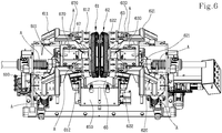
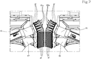
- each guide element (61,62) comprises a plurality of cursors (61 a,62a) movable along a path closed in a loop.
- the paths of the cursors (61a,62a) could be converging to one another or directed parallel to the longitudinal direction (Y).
- the cursors (61 a,62a) may be associated for example with an articulated chain, which is closed in a loop and movable by gears in a way that is known to a person skilled in the art.
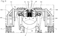
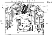
- Figures 2 , 3 , 4 schematically show two rotary actuators (M1,M2) each of which is associated with a motor gear (G1,G2) of an articulated chain with which the cursors (61 a,62a) are associated.
- At least an active portion of the path followed by the cursors (61 a,62a) is arranged in proximity to the edges (E1,E2) of the profile (P) itself, so that along such active portion the cursors (61a,62a) may be arranged in contact with the profile (P) following it in a synchronous way as it advances.
- the cursors (61 a,62a) are activated in advancement along the active portion of their own path at the same speed as the profile (P). This allows any sliding or slithering on the surface of the profile (P) to be prevented, even in presence of a determined pressure exerted by the cursors (61 a,62a) on the surface itself.
- Each cursor (61 a,62a) has an active face (Af) which is intended to come into contact with the profile (P) along the active portion of the path.
- Such face has, on a vertical sectional plane perpendicular to the longitudinal axis of the profile (P), a profile counter-shaped to the outline of the profile (P).
- each cursor (61 a,62a) has an active face that has the same curvature as the profile (P) at least in the zone of the edges (E1,E2).
- each cursor (61a,62a) exhibits a generally prismatic conformation comprising the active face (Af).
- the cursors (61a,62a) are distributed into two distinct groups.
- a first group of cursors (61 a) is intended to be positioned in contact with a first edge (E1) of the profile (P).
- a second group of cursors (61 b) is intended to be positioned in contact with a second edge (E2) of the profile (P).
- each group of cursors (61 a,62a), associated with its own chain or drive belt takes the form of a track, in which the active portion is activated in synchronous sliding with the profile (P).
- the alignment unit comprises vertical adjustment means for allowing the vertical position of each guide element (61,62) to be adjusted.
- such vertical adjustment means is structured for allowing the inclination of each guide element (61,62) to be adjusted on a vertical plane.
- the alignment unit comprises horizontal adjustment means for allowing the horizontal position of each guide element (61,62) to be adjusted.
- such horizontal adjustment means is structured for allowing the inclination of each guide element (61,62) to be adjusted on a horizontal plane.
- each guide element (61,62) may be advantageously associated with a respective support (610,620).
- Such supports (610,620) may be connected to a frame bearing the alignment unit.
- each support (610,620) is movable along a vertical direction, by actuators (A) known to a person skilled in the art, to allow the adjustment of the vertical position of the guide elements (61,62).
- each support (610,620) comprises a pair of arms (611,621) movable independently from one another and arranged at opposite ends of the respective guide element (61,62) In this way the position of the guide elements (61,62) may also be adjusted by inclination on a vertical plane.
- the arms (611,621) have an L-shaped conformation, with an upper cross portion connected to the respective guide element (61,62).
- each arm (611,621) and the respective guide element (61,62) is performed through a shaped body (612,622) whose position can be adjusted along a horizontal direction.
- each shaped body (612,622) is provided with slots arranged horizontally through which it can be coupled to the respective arm (612,622), for example through screws.
- each shaped body (612,622) is provided with an actuator (A), for example a worm screw, structured for producing a movement directed vertically.
- the position of the guide elements (61,62) can therefore be adjusted on a vertical plane with the possibility to adjust also the inclination on a vertical plane.
- the welding means (4) could however be positioned downstream of the alignment means. In the embodiment shown the two groups of cursors (61 a,62a) are separated by the longitudinal slit (7).
- the alignment unit according to the present invention further comprises a plurality of shaped rollers (63,64,65,66,67).
- the projection of the shaped rollers (63,64,65,66,67) on a plane perpendicular to the longitudinal axis of the profile (P) generally envelops a circular outline.
- the shaped rollers comprise a lower roller (65), a first lateral roller (64), a second lateral roller (66), a first upper roller (63) and a second upper roller (67).
- the two lateral rollers and the two upper rollers are arranged symmetrically with respect to a vertical medium plane containing the longitudinal direction (Y).
- the shaped rollers have axes of rotation which, preferably, lie on the same vertical plane. This allows the overall dimensions of the structure along the longitudinal direction (Y) to be reduced.
- each shaped roller is movable in an interrelated or independent way with respect to one another so as to change the position in space of their axis of rotation. This allows the outline enveloped by the shaped rollers to be changed.
- each shaped roller is associated with a support that is movable with respect to the frame bearing the alignment unit.
- the lateral rollers are movable simultaneously and symmetrically with respect to a vertical plane containing the longitudinal axis (Y) of the profile (P).
- bracket support (650) whose position can be adjusted vertically.
- the movement of the bracket support (650) may be obtained by actuator means known to a person skilled in the art.
- the two lateral rollers (64,66) are each mounted on a respective bracket support (640,660) whose position can be adjusted horizontally.
- the movement and adjustment of the bracket supports (640,660) may be obtained by actuator means known to a person skilled in the art.
- the two upper rollers (63,67) are each mounted on a respective bracket support (630,670) whose position can be adjusted horizontally.
- the movement and adjustment of the bracket supports (630,670) may also be obtained by actuator means known to a person skilled in the art.
- the figures show a plurality of actuators, all indicated with the letter A, to be used for adjusting the position of the brackets mentioned above.
- actuators may for example be oil dynamic cylinders, screw mechanisms, rack mechanisms or the like.
- the alignment unit provides important advantages. Above all, it allows the longitudinal edges of the profile to be perfectly aligned, which edges assume a rectilinear and parallel configuration. This allows optimal welding to be achieved. Furthermore, the alignment unit may also be adopted in profiling lines that are already operating, with limited adaptation interventions.
Landscapes
- Engineering & Computer Science (AREA)
- Mechanical Engineering (AREA)
- Physics & Mathematics (AREA)
- Optics & Photonics (AREA)
- Butt Welding And Welding Of Specific Article (AREA)
- Bending Of Plates, Rods, And Pipes (AREA)
Applications Claiming Priority (1)
| Application Number | Priority Date | Filing Date | Title |
|---|---|---|---|
| ITUB2016A000289A ITUB20160289A1 (it) | 2016-01-27 | 2016-01-27 | Gruppo di allineamento per una linea profilatrice |
Publications (1)
| Publication Number | Publication Date |
|---|---|
| EP3199291A1 true EP3199291A1 (de) | 2017-08-02 |
Family
ID=55919868
Family Applications (1)
| Application Number | Title | Priority Date | Filing Date |
|---|---|---|---|
| EP17152783.1A Withdrawn EP3199291A1 (de) | 2016-01-27 | 2017-01-24 | Ausrichtungseinheit für eine profilierungsanlage |
Country Status (4)
| Country | Link |
|---|---|
| US (1) | US20170209911A1 (de) |
| EP (1) | EP3199291A1 (de) |
| JP (1) | JP2017131967A (de) |
| IT (1) | ITUB20160289A1 (de) |
Cited By (1)
| Publication number | Priority date | Publication date | Assignee | Title |
|---|---|---|---|---|
| CN113560805A (zh) * | 2021-07-29 | 2021-10-29 | 泰安隆泰金属制品有限公司 | 一种金属制品加工用弯管焊接装置 |
Citations (3)
| Publication number | Priority date | Publication date | Assignee | Title |
|---|---|---|---|---|
| US2792799A (en) * | 1949-06-09 | 1957-05-21 | United States Steel Corp | Seam welding apparatus |
| US3056535A (en) * | 1960-05-24 | 1962-10-02 | Continental Can Co | Tube pulling mechanism for continuous welding machines |
| US3145758A (en) * | 1961-01-23 | 1964-08-25 | Mobile Pipe Corp | Apparatus for continuous forming of metal shapes |
Family Cites Families (7)
| Publication number | Priority date | Publication date | Assignee | Title |
|---|---|---|---|---|
| US2845038A (en) * | 1954-08-09 | 1958-07-29 | Thomas J Crawford | Seam guide assembly |
| JPS55139182A (en) * | 1979-04-16 | 1980-10-30 | Nisshin Steel Co Ltd | Pipe making method and apparatus by melting and welding |
| JPH0353825Y2 (de) * | 1986-04-28 | 1991-11-26 | ||
| US5865053A (en) * | 1996-02-20 | 1999-02-02 | Abbey Etna Machine Company | Transition beam forming section for tube mill |
| JP3986979B2 (ja) * | 2003-02-19 | 2007-10-03 | 彰久 村田 | 単管連続自動溶接装置 |
| RU2551722C2 (ru) * | 2010-11-04 | 2015-05-27 | Наката Мэньюфэкчеринг Ко., Лтд. | Способ формования и формовочная машина |
| US9399895B2 (en) * | 2011-09-02 | 2016-07-26 | National Oilwell Varco L.P. | Coiled tubing injector head with chain guides |
-
2016
- 2016-01-27 IT ITUB2016A000289A patent/ITUB20160289A1/it unknown
-
2017
- 2017-01-24 EP EP17152783.1A patent/EP3199291A1/de not_active Withdrawn
- 2017-01-26 US US15/416,003 patent/US20170209911A1/en not_active Abandoned
- 2017-01-26 JP JP2017012189A patent/JP2017131967A/ja active Pending
Patent Citations (3)
| Publication number | Priority date | Publication date | Assignee | Title |
|---|---|---|---|---|
| US2792799A (en) * | 1949-06-09 | 1957-05-21 | United States Steel Corp | Seam welding apparatus |
| US3056535A (en) * | 1960-05-24 | 1962-10-02 | Continental Can Co | Tube pulling mechanism for continuous welding machines |
| US3145758A (en) * | 1961-01-23 | 1964-08-25 | Mobile Pipe Corp | Apparatus for continuous forming of metal shapes |
Cited By (1)
| Publication number | Priority date | Publication date | Assignee | Title |
|---|---|---|---|---|
| CN113560805A (zh) * | 2021-07-29 | 2021-10-29 | 泰安隆泰金属制品有限公司 | 一种金属制品加工用弯管焊接装置 |
Also Published As
| Publication number | Publication date |
|---|---|
| JP2017131967A (ja) | 2017-08-03 |
| ITUB20160289A1 (it) | 2017-07-27 |
| US20170209911A1 (en) | 2017-07-27 |
Similar Documents
| Publication | Publication Date | Title |
|---|---|---|
| JP5033120B2 (ja) | 形材を成形加工する生産ラインおよび方法 | |
| RU2010145269A (ru) | Изогнутая во множестве направлений балка, устройство роликового формования и способ | |
| CN102170979A (zh) | 用于将横截面可变化的型材冷轧成型的系统 | |
| US9192972B2 (en) | Forming method and forming device | |
| US20110017804A1 (en) | Variable linear geometry machine for continuously forming square tubes | |
| JP2008539083A5 (de) | ||
| PL200194B1 (pl) | Sposób i urządzenie do wytwarzania wygiętych odcinków taśmy sprężynowej | |
| SE528078C2 (sv) | Sätt att i en produktionslinje forma profiler | |
| KR101260867B1 (ko) | 모자형 프로파일을 롤 성형하기 위한 방법 및 롤 성형기 | |
| CN112845715A (zh) | 一种数控四轴一次滚弯等曲率成形装备 | |
| US20170209911A1 (en) | Alignment unit for a profiling line | |
| US4487046A (en) | Transition forming section for tube mill | |
| JP3501482B2 (ja) | ロール成形方法、ロール成形装置のロール姿勢制御装置およびロール姿勢制御方法ならびにモールの製造方法 | |
| EP2520170B1 (de) | Vorrichtung zum Herstellen von Teigformlingen, insbesondere zum Formen von Croissants | |
| EP2165779B1 (de) | Maschine mit variabler linearer Struktur zur Formung von Rohren | |
| US1710262A (en) | Method for forming fashioned molding | |
| EP3243577B1 (de) | Umformeinheit für eine profilierungsanlage | |
| US2164836A (en) | Production of profiled sections from sheet metal by rolling | |
| CN216072426U (zh) | 一种模切辊浮动机构 | |
| KR20140105565A (ko) | 롤 포밍기 및 롤 포밍 방법 | |
| KR20150079304A (ko) | 가변 롤 포밍 유닛 | |
| CN113633470A (zh) | 一种卫生用品折叠装置及该装置的实施方法 | |
| US8522589B2 (en) | Machine of variable linear structure for the formation of tubes | |
| US11878337B2 (en) | Roll-forming machine and method for roll-forming | |
| KR101444179B1 (ko) | 가변 롤 포밍 유닛 |
Legal Events
| Date | Code | Title | Description |
|---|---|---|---|
| PUAI | Public reference made under article 153(3) epc to a published international application that has entered the european phase |
Free format text: ORIGINAL CODE: 0009012 |
|
| AK | Designated contracting states |
Kind code of ref document: A1 Designated state(s): AL AT BE BG CH CY CZ DE DK EE ES FI FR GB GR HR HU IE IS IT LI LT LU LV MC MK MT NL NO PL PT RO RS SE SI SK SM TR |
|
| AX | Request for extension of the european patent |
Extension state: BA ME |
|
| 17P | Request for examination filed |
Effective date: 20180111 |
|
| RBV | Designated contracting states (corrected) |
Designated state(s): AL AT BE BG CH CY CZ DE DK EE ES FI FR GB GR HR HU IE IS IT LI LT LU LV MC MK MT NL NO PL PT RO RS SE SI SK SM TR |
|
| 17Q | First examination report despatched |
Effective date: 20180621 |
|
| STAA | Information on the status of an ep patent application or granted ep patent |
Free format text: STATUS: THE APPLICATION IS DEEMED TO BE WITHDRAWN |
|
| 18D | Application deemed to be withdrawn |
Effective date: 20190813 |