EP3199230A1 - Device for continuously mixing at least two substances - Google Patents
Device for continuously mixing at least two substances Download PDFInfo
- Publication number
- EP3199230A1 EP3199230A1 EP16153557.0A EP16153557A EP3199230A1 EP 3199230 A1 EP3199230 A1 EP 3199230A1 EP 16153557 A EP16153557 A EP 16153557A EP 3199230 A1 EP3199230 A1 EP 3199230A1
- Authority
- EP
- European Patent Office
- Prior art keywords
- mixing
- substances
- mixing chamber
- rotor
- magnetic
- Prior art date
- Legal status (The legal status is an assumption and is not a legal conclusion. Google has not performed a legal analysis and makes no representation as to the accuracy of the status listed.)
- Withdrawn
Links
Images

Classifications
-
- B—PERFORMING OPERATIONS; TRANSPORTING
- B01—PHYSICAL OR CHEMICAL PROCESSES OR APPARATUS IN GENERAL
- B01F—MIXING, e.g. DISSOLVING, EMULSIFYING OR DISPERSING
- B01F23/00—Mixing according to the phases to be mixed, e.g. dispersing or emulsifying
- B01F23/10—Mixing gases with gases
- B01F23/14—Mixing gases with gases with moving mixing elements, e.g. with liquid seal
-
- B—PERFORMING OPERATIONS; TRANSPORTING
- B01—PHYSICAL OR CHEMICAL PROCESSES OR APPARATUS IN GENERAL
- B01F—MIXING, e.g. DISSOLVING, EMULSIFYING OR DISPERSING
- B01F25/00—Flow mixers; Mixers for falling materials, e.g. solid particles
- B01F25/40—Static mixers
- B01F25/45—Mixers in which the materials to be mixed are pressed together through orifices or interstitial spaces, e.g. between beads
- B01F25/451—Mixers in which the materials to be mixed are pressed together through orifices or interstitial spaces, e.g. between beads characterised by means for moving the materials to be mixed or the mixture
-
- B—PERFORMING OPERATIONS; TRANSPORTING
- B01—PHYSICAL OR CHEMICAL PROCESSES OR APPARATUS IN GENERAL
- B01F—MIXING, e.g. DISSOLVING, EMULSIFYING OR DISPERSING
- B01F27/00—Mixers with rotary stirring devices in fixed receptacles; Kneaders
- B01F27/27—Mixers with stator-rotor systems, e.g. with intermeshing teeth or cylinders or having orifices
- B01F27/271—Mixers with stator-rotor systems, e.g. with intermeshing teeth or cylinders or having orifices with means for moving the materials to be mixed radially between the surfaces of the rotor and the stator
-
- B—PERFORMING OPERATIONS; TRANSPORTING
- B01—PHYSICAL OR CHEMICAL PROCESSES OR APPARATUS IN GENERAL
- B01F—MIXING, e.g. DISSOLVING, EMULSIFYING OR DISPERSING
- B01F33/00—Other mixers; Mixing plants; Combinations of mixers
- B01F33/45—Magnetic mixers; Mixers with magnetically driven stirrers
- B01F33/453—Magnetic mixers; Mixers with magnetically driven stirrers using supported or suspended stirring elements
- B01F33/4531—Magnetic mixers; Mixers with magnetically driven stirrers using supported or suspended stirring elements using an axis supported in several points for mounting the stirring element
-
- B—PERFORMING OPERATIONS; TRANSPORTING
- B01—PHYSICAL OR CHEMICAL PROCESSES OR APPARATUS IN GENERAL
- B01F—MIXING, e.g. DISSOLVING, EMULSIFYING OR DISPERSING
- B01F33/00—Other mixers; Mixing plants; Combinations of mixers
- B01F33/45—Magnetic mixers; Mixers with magnetically driven stirrers
- B01F33/453—Magnetic mixers; Mixers with magnetically driven stirrers using supported or suspended stirring elements
- B01F33/4532—Magnetic mixers; Mixers with magnetically driven stirrers using supported or suspended stirring elements using a bearing, tube, opening or gap for internally supporting the stirring element
Definitions
- the invention relates to a device for continuously mixing at least two substances.
- this device is used for mixing di- and polyamines of the diphenylmethane series (hereafter MDA total) with carbon monoxide (phosgene) for the preparation of di- and polyisocyanates of the diphenylmethane series (henceforth MDI).
- MDI polyurethanes
- MDA carbon dioxide dichloride
- the phosgene should be used in hermetically closed circuits.
- the mixing devices used must be hermetically sealed; Sealing rings on rotating components can not adequately provide this hermetic seal according to the required safety.
- Phosgene is added to the reaction in proportion to MDA in excess of the stoichiometrically exact amount.
- the supplied MDA should be fully implemented, while a certain amount of phosgene remains unreacted in the starting material. The excess should be adjusted as low as possible for economic reasons, so that the amount of recirculated phosgene is minimized.
- the input materials MDA and phosgene are dissolved in the preparation of MDI in a solvent such as monochlorobenzene (MCB) or ortho-dichlorobenzene, which promotes viscosity and miscibility.
- a solvent such as monochlorobenzene (MCB) or ortho-dichlorobenzene, which promotes viscosity and miscibility.
- MBB monochlorobenzene
- ortho-dichlorobenzene which promotes viscosity and miscibility.
- the solvent in the purchase and disposal is quite expensive; therefore it is processed by distillation and used several times. This distillation is associated with an energy input and is therefore costly. For economic reasons, therefore, efforts are always made to keep the proportion of solvent as low as possible.
- the reaction of MDA and phosgene is an exothermic reaction. Due to the reactivity, local temperature peaks arise, which have to be reduced; the local temperatures in the mixing room should not exceed about 145 ° C, in order to produce no unwanted by-products.
- the cooling is usually provided by the solvent. However, if you reduce the proportion of the solvent, so the cooling agent is also saved to cool the reaction.
- MDA * HCl solid MDA hydrochloride
- MDA * HCl solid MDA hydrochloride
- MDA * HCl solid MDA hydrochloride
- This reaction is undesirable in itself, but can not be completely avoided.
- the more critical the formation of MDA * HCl the finer the MDA * HCl.
- the MDA * HCl can in turn be converted to the MDI with phosgene, so it is not lost for the target reaction. This reaction proceeds the better, the finer the MDA * HCl.
- Another factor that influences this reaction is the solubility of MDA * HCl in the solvent, which increases with increasing temperature.
- phosgene tends to outgas at too high a temperature. This can be counteracted by increasing the pressure in the mixing chamber to at least 20 bar, preferably more than 30 bar.
- Such a mixer comprises a rotor with a plurality of radially aligned bolts.
- the mixing takes place here on an outer circumference of the mixer (see also EP 2 077 150 A1 ).
- rotational speeds of more than 1000 U / min are set.
- rotational speeds of the rotor-stator mixer of at least 3000 U / min are desired.
- the device according to the invention for continuously mixing at least two substances comprises a mixing space in which a mixing element, in particular a rotor-stator mixer is arranged, at least two inlets through which the substances to be mixed are introduced separately and continuously into the mixing space, at least one drain for the continuous filling of the mixing chamber produced product from the mixing chamber and also a drive arrangement for driving the mixing element.
- the device is suitable and is especially used for mixing MDA with carbon monoxide (phosgene) to produce MDI.
- the solvent used is in particular MCB (chlorobenzene).
- the mixing chamber is hermetically enclosed by a housing. Rotating members rotatably connected to the mixing element are disposed entirely within the hermetic enclosure. This means in particular that no rotating parts penetrate the hermetically enclosing housing, which is a prerequisite for a high level of safety against undesired escape of highly toxic substances.
- the invention is characterized in that the drive arrangement comprises an arrangement for generating a rotating magnetic field, which is arranged completely outside the hermetically enclosing housing.
- This arrangement may comprise a motor and a first magnet element rotatably driven therewith, and is disposed entirely outside the hermetically enclosing housing.
- the drive arrangement comprises a second magnetic element, which is arranged completely within the hermetically enclosing housing and is in magnetic drive connection with the arrangement, in particular the first magnetic element.
- the second magnetic element is rotatably connected to the mixing element.
- the second magnetic element in this case represents a kind of stirring fish, which is arranged in the mixing chamber, and causes by its rotation a mixing of the introduced substances.
- the second magnetic element may be formed integrally with the mixing element.
- the second magnetic element is a spiked ring, which is associated with a rotor-stator mixer.
- the second magnetic element is mounted in contrast to known magnetic stirrers in the mixing chamber, in particular based on magnetic bearings.
- the device comprises a rotor-stator mixer arrangement with a spiked ring.
- a spiked ring is rotatably supported in the mixing space about an axis of rotation.
- a plurality of circular and coaxial arranged around the axis of rotation of the spiked inflows is provided for the separate introduction of the substances into the mixing chamber.
- Continuous mixing is understood in particular to mean that the substances undergo a largely constant flow during the mixing process, and that in the mixing chamber produced product is constantly discharged.
- static mixing operations are understood as those in which first all the substances to be mixed are introduced in a mixing chamber in a chord, then the inflow is stopped and mixing takes place and after complete mixing the end product is removed from the mixing chamber; only then refilling with substances to be mixed. Such static mixing operations are not encompassed by the term continuous introduction.
- the spiked ring is arranged directly axially adjacent to the tributaries.
- Axially adjacent means that in the axial direction (ie in a direction parallel to the axis of rotation) a maximum of a narrow gap, in particular less than 2 mm, is provided between the outlet of the inflows and the spiked ring.
- the mixing element is supported by magnetic bearings.
- Such magnetic bearings may be formed without contact; that is, there is no contact between relative moving parts at these bearings.
- high rotational speeds can be realized without friction and thus heat exposure between the elements involved occurs.
- the device described above is used for the continuous mixing of at least two substances, in particular diaminodiphenylmethane MDA and carbon dioxide dichloride (phosgene).
- the pressure in the mixing chamber is preferably at least 19 bar, preferably at least 20 bar, more preferably at least 30 bar.
- the mixing element is operated at a rotational speed of at least 3000 revolutions per minute.
- the temperature in the mixing chamber is in particular a maximum of 135 ° C, preferably 85 ° C.
- a magnetic coupling is essentially designed such that the interior of the magnetic coupling becomes the mixing and reaction space.
- the second magnetic element can be embodied as an anchor stirrer or stirring fish with, for example, Teflon-coated permanent magnets, which are driven by the first magnetic element arranged outside the housing. So can be very high Torques in the range of a few Nm achieve in small gap cans, which allows the required mechanical power inputs in the range of several kW. Similarly, very high speeds are possible, so that the peripheral speeds (20-30 m / s) of the production mixers are achieved, which is an important parameter for scale-up investigations.
- the required high speeds can be made possible with magnetic and / or hydraulic storage of the inner rotor. Since the question of the need for purge and cooling flows also applies to larger magnetically driven intensive mixers (eg rotor-stator mixers in the production of MDI), an application of the invention on a larger scale, in particular in the production of MDI, advantageous because so inert side streams can be avoided in particular by solvent, which is beneficial to a reduction of cycle streams.
- larger magnetically driven intensive mixers eg rotor-stator mixers in the production of MDI
- the excess of phosgene at given target NCO levels can be reduced if free MDA is no longer available for side reactions to ureas. In this case, the excess can be reduced to almost zero, so that a use of phosgene is possible quite close to or exactly at the stoichiometric ratio.
- the phosgene holdup in the plant part can significantly reduce, which is seen as increasingly critical safety aspect.
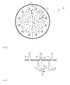
- FIG. 1 to FIG. 3 show a mixing device 1 with a rotor-stator mixer assembly of the conventional type.
- a mixing chamber 4 two substances X, Y are supplied separately and continuously via inlets 3.
- the substances X, Y are dissolved in a solvent L.
- a mixing device 6 is provided in the form of a rotor-stator mixer.
- This rotor-stator mixer 6 comprises a plurality of spiked rings 7. At each spiked ring 7 protrude radially single spikes 8.
- the spiked rings 7 are held on a common rotary shaft 14 and rotatably connected to each other.
- the motor 9 includes a stator 10 and a rotor 11.
- An electrical lead 12 is connected to the stator.
- the rotor 11 is rotatably connected to the shaft 14.
- the mixing device 1 comprises a hermetically sealed housing 2, in which all rotating parts of the mixing device 1 are located, in particular the spiked ring 7, the rotor 11 and the shaft 14. Also bearings 13 for supporting the shaft 14 are held within the hermetically sealed housing 2 , The stators 10 of the motor are held outside the housing 2.
- a partition 22 separates the interior of the housing 2 in two different spaces, to one the mixing chamber 4, on the other hand, the rotor chamber 21. In the last is the rotor 12 is received. Essentially, it is prevented by the partition 22 that fluid can flow from the mixing chamber 4 into the rotor chamber 21, only individual slots 23 in the region of the partition or the bearings are provided to allow a solvent flow L from the rotor chamber 21 into the mixing chamber 4. This solvent flow serves for a cooling of the rotor 11; On the other hand, this solvent flow L should ensure that none of the substances X, Y or the final product Z reaches the rotor space 21.
- the two substances X and Y are mixed to the final product Z.
- the substances X and Y are dissolved in the solvent L before.
- the final product Z is dissolved in the solvent L.
- the end product Z flows in dissolved form completely from the mixing chamber 4 and enters a solvent separator 18, in which the solvent L is separated from the end product X.
- the separated solvent L passes into a solvent treatment 19, and from there the solvent passes again into the Rotor space 21 for cooling and purging the rotor; Further, the solvent L is used again for dissolving the substances X, Y (not shown).
- FIG. 2 and FIG. 3 Details of the rotor-stator mixer are shown.
- the spiked ring 7 rotates in the direction of rotation D about the axis of rotation A.
- the spiked ring 7 also has twelve spikes, the inlets are arranged adjacent to each other in the circumferential direction.
- the number of spikes 8 on a spiked ring 7 coincides with the number of circumferentially distributed inlets 3.
- the spikes 8 are shown in cross-section. It can be seen that the spikes 8 are only spaced from the tributaries 3 by an axial gap of a few millimeters. In the radially outer region, which is in overlap with the tributaries 3, the spike 8 has a bevel 15. This chamfer 15 serves to entrain the flow S of the inflowing substances from the axial direction, as it first flows out of the inflows 3, in the direction of rotation D. First, an acceleration of the substances in the circumferential direction is thus effected by the rotor-stator mixer.
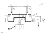
- FIG. 4 is now a modification of the mixing device according to FIG. 1 shown, wherein the described details of the mixing device according to the figures FIG. 1 to FIG. 3 largely on the mixing devices according to the invention according to the figures FIG. 4 and FIG. 5 are applicable.
- FIG. 4 shows a mixing device 1 with a rotor-stator mixer 6, comprising a significantly smaller hermetically sealed housing 2 as the mixing device according to FIG. 1 ,
- the motor 9 is a commercial motor, which is supplied via a power line 12 with electrical energy.
- a magnetic disk 16 (first magnetic element) is driven via a shaft 14 "The motor 9, the shaft 14 and the magnetic disk 16 are arranged outside the housing 2.
- Within of the housing 16 is a magnetic stirring fish 17 (second magnetic element) is arranged, which is integrally formed with a spiked ring 7.
- the spiked ring 7 rotates and causes a mixture, as it already has FIG. 1 was shown.
- the separate solvent flow for cooling and purging parts of the engine can be omitted.
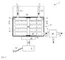
- FIG. 5 shows a modification of the device according to FIG. 4 ,
- the rotor-stator mixer 17 which is integrally formed with a spiked ring 7 more spiked rings 7 are provided, which are arranged axially adjacent to the stirring fish 17 and are connected to each other via a shaft 14 '.
- the shaft 14 ' is mounted in the housing 2.
Abstract
Vorrichtung (1) zum kontinuierlichen Vermischen zumindest zweier Substanzen (X, Y), insbesondere von Diaminodiphenylmethan (MDA) mit Kohlenoxiddichlorid (Phosgen), umfassend - einen Mischraum (4), in dem ein Mischelement (6), insbesondere ein Rotor-Stator-Mischer, (6) angeordnet ist, - zumindest zwei Zuläufe (3), durch welche die zu mischenden Substanzen separat und kontinuierlich in den Mischraum (4) einführbar sind, - zumindest einen Ablauf (5) zum kontinuierlichen Abführen des im Mischraum (4) erzeugten Produkts (Z) aus dem Mischraum (4) hinaus, - eine Antriebsanordnung (9, 16, 17) zum Antreiben des Mischelements (6), wobei der Mischraum (4) durch ein Gehäuse (2) hermetisch umschlossen ist, wobei Teile (17) der Antriebsanordnung, die drehfest mit dem Mischelement (6) verbunden sind, vollständig innerhalb des hermetisch umschließenden Gehäuses (2) angeordnet sind, wobei die Antriebsanordnung (9, 16, 17) eine Anordnung (9, 16) zur Erzeugung eines rotierenden Magnetfeldes umfasst, welche vollständig außerhalb des hermetisch umschließenden Gehäuses (2) angeordnet ist, und dass die Antriebsanordnung (9, 16, 17) ein zweites Magnetelement (17) umfasst, welches vollständig innerhalb des hermetisch umschließenden Gehäuses (2) angeordnet ist und mit der Anordnung, insbesondere dem ersten Magnetelement (16), in magnetischer Antriebsverbindung steht und mit dem Mischelement (6) drehfest verbunden ist.Device (1) for continuously mixing at least two substances (X, Y), in particular diaminodiphenylmethane (MDA) with carbon dioxide dichloride (phosgene) a mixing space (4) in which a mixing element (6), in particular a rotor-stator mixer (6), is arranged, - At least two inlets (3) through which the substances to be mixed separately and continuously inserted into the mixing chamber (4), at least one outlet (5) for continuously discharging the product (Z) produced in the mixing chamber (4) out of the mixing chamber (4), a drive arrangement (9, 16, 17) for driving the mixing element (6), wherein the mixing chamber (4) is hermetically enclosed by a housing (2), wherein parts (17) of the drive assembly which are non-rotatably connected to the mixing element (6) are arranged completely inside the hermetically enclosing housing (2), the drive arrangement (9, 16, 17) comprising an arrangement (9, 16) for generating a rotating magnetic field which is arranged completely outside the hermetically enclosing housing (2), and the drive arrangement (9, 16, 17) comprises a second magnet element (17) which is arranged completely inside the hermetically enclosing housing (2) and is in magnetic drive connection with the arrangement, in particular the first magnet element (16), and with the magnet Mixing element (6) is rotatably connected.
Description
Die Erfindung betrifft eine Vorrichtung zum kontinuierlichen Vermischen zumindest zweier Substanzen. Insbesondere wird diese Vorrichtung verwendet zum Vermischen von Di- und Polyaminen der Diphenylmethanreihe (fortan summarisch MDA) mit Kohlenoxiddichlorid (Phosgen) zur Herstellung von Di- und Polyisocyanaten der Diphenylmethanreihe (fortan MDI).The invention relates to a device for continuously mixing at least two substances. In particular, this device is used for mixing di- and polyamines of the diphenylmethane series (hereafter MDA total) with carbon monoxide (phosgene) for the preparation of di- and polyisocyanates of the diphenylmethane series (henceforth MDI).
Für die Herstellung von zahlreichen Polyurethanen (PUR) wird MDI benötigt. MDI wird großtechnisch durch eine Phosgenierung von MDA erzeugt. Aufgrund der überaus hohen Reaktivität des Kohlenoxiddichlorids (Phosgens) findet die Reaktion zwischen MDA und Phosgen unmittelbar nach einer Vermischung der beiden Stoffe miteinander statt.For the production of numerous polyurethanes (PUR) MDI is required. MDI is produced industrially by a phosgenation of MDA. Due to the extremely high reactivity of the carbon dioxide dichloride (phosgene), the reaction between MDA and phosgene takes place immediately after mixing the two substances together.
Bei der großtechnischen Durchführung dieser Phosgenierung sind einige Rahmenbedingungen zu berücksichtigen. Zunächst sind sämtliche der beteiligten Stoffe giftig. Ein Austritt der Stoffe ist daher zu vermeiden. Insbesondere sollte das Phosgen in hermetisch geschlossenen Kreisläufen eingesetzt werden. Die eingesetzten Mischvorrichtungen müssen hermetisch dicht sein; Dichtringe an sich drehenden Bauteilen können diese hermetische Dichtheit entsprechend der geforderten Sicherheit nicht ausreichend bereitstellen.In the large-scale implementation of this phosgenation some framework conditions are taken into account. First, all the substances involved are toxic. An escape of the substances is therefore to be avoided. In particular, the phosgene should be used in hermetically closed circuits. The mixing devices used must be hermetically sealed; Sealing rings on rotating components can not adequately provide this hermetic seal according to the required safety.
Phosgen wird der Reaktion im Verhältnis zu MDA im Überschuss gegenüber der stöchiometrisch exakten Menge zugeführt. Dabei soll das zugeführte MDA vollständig umgesetzt werden, während eine gewisse Menge an Phosgen unreagiert im Ausgangsprodukt verbleibt. Der Überschuss sollte aus wirtschaftlichen Gründen möglichst gering eingestellt werden, damit die Menge an zurückgeführtem Phosgen möglichst gering ist.Phosgene is added to the reaction in proportion to MDA in excess of the stoichiometrically exact amount. The supplied MDA should be fully implemented, while a certain amount of phosgene remains unreacted in the starting material. The excess should be adjusted as low as possible for economic reasons, so that the amount of recirculated phosgene is minimized.
Die Eingangsstoffe MDA und Phosgen werden für die Herstellung von MDI in einem Lösungsmittel wie beispielsweise Monochlorbenzol (MCB) oder ortho-Dichlorbenzol gelöst, was die Viskosität und die Vermischbarkeit begünstigt. Allerdings ist das Lösungsmittel in der Anschaffung und der Entsorgung recht kostenaufwändig; daher wird es durch Destillation aufbereitet und mehrfach verwendet. Diese Destillation geht mit einem Energieeintrag einher und ist daher kostenaufwändig. Daher ist man aus wirtschaftlichen Überlegungen stets bestrebt, den Anteil an Lösungsmittel möglichst gering zu halten.The input materials MDA and phosgene are dissolved in the preparation of MDI in a solvent such as monochlorobenzene (MCB) or ortho-dichlorobenzene, which promotes viscosity and miscibility. However, the solvent in the purchase and disposal is quite expensive; therefore it is processed by distillation and used several times. This distillation is associated with an energy input and is therefore costly. For economic reasons, therefore, efforts are always made to keep the proportion of solvent as low as possible.
Die Reaktion aus MDA und Phosgen ist eine exotherme Reaktion. Aufgrund der Reaktivität ergeben sich lokale Temperaturspitzen, die abzubauen sind; die lokalen Temperaturen im Mischraum sollten ca. 145°C nicht überschreiten, um keine unerwünschten Nebenprodukte zu erzeugen. Die Kühlung wird üblicherweise durch das Lösungsmittel bereitgestellt. Reduziert man allerdings den Anteil des Lösungsmittels, so wird folglich auch das Kühlmittel zur Kühlung der Reaktion eingespart.The reaction of MDA and phosgene is an exothermic reaction. Due to the reactivity, local temperature peaks arise, which have to be reduced; the local temperatures in the mixing room should not exceed about 145 ° C, in order to produce no unwanted by-products. The cooling is usually provided by the solvent. However, if you reduce the proportion of the solvent, so the cooling agent is also saved to cool the reaction.
Des Weiteren neigt der als Koppelprodukt gebildete Chlorwasserstoff dazu, mit MDA zu festem MDA-Hydrochlorid (MDA*HCl) zu reagieren. Diese Reaktion ist an sich unerwünscht, lässt sich aber nicht vollständig vermeiden. Die Bildung von MDA*HCl ist umso unkritischer, desto feinkörniger das MDA*HCl ist. Das MDA*HCl kann wiederum mit Phosgen letztendlich zum MDI umgesetzt werden, ist also für die Zielreaktion nicht verloren. Diese Umsetzung verläuft umso besser, je feinkörniger das MDA*HCl ist. Ein weiterer Faktor, der diese Reaktion beeinflusst, ist die Löslichkeit des MDA*HCl im Lösungsmittel, die mit steigender Temperatur steigt. Andererseits neigt Phosgen dazu, bei zu hoher Temperatur auszugasen. Dem kann durch eine Erhöhung des Drucks in der Mischkammer auf zumindest 20 bar, vorzugsweise mehr als 30 bar entgegengetreten werden.Furthermore, the by-product hydrogen chloride tends to react with MDA to form solid MDA hydrochloride (MDA * HCl). This reaction is undesirable in itself, but can not be completely avoided. The more critical the formation of MDA * HCl, the finer the MDA * HCl. The MDA * HCl can in turn be converted to the MDI with phosgene, so it is not lost for the target reaction. This reaction proceeds the better, the finer the MDA * HCl. Another factor that influences this reaction is the solubility of MDA * HCl in the solvent, which increases with increasing temperature. On the other hand, phosgene tends to outgas at too high a temperature. This can be counteracted by increasing the pressure in the mixing chamber to at least 20 bar, preferably more than 30 bar.
Eine Erhöhung des Drucks im Reaktionsraum auf zumindest 20 bar setzt allerdings massiv höhere Sicherheitsanforderung an die Mischeinrichtung voraus, da, wie bereits ausgeführt, es sich bei den Ausgangsstoffen um giftige Stoffe handelt. Ein Austritt der Stoffe auch in kleinen Mengen muss ausgeschlossen sein.Increasing the pressure in the reaction space to at least 20 bar, however, requires massively higher safety requirements for the mixing device, since, as already stated, the starting materials are toxic substances. A leakage of substances even in small quantities must be excluded.
Bislang werden beispielsweise für die Vermischung von MDA und Phosgen Aggregate eingesetzt, die auf Rotoren und Statoren beruhen. Ein solcher Mischer umfasst einen Rotor mit einer Mehrzahl von radial ausgerichteten Bolzen. Die Vermischung erfolgt hier an einem Außenumfang des Mischers (siehe auch
Um bei hohem Druck und erhöhter Temperatur dennoch eine gute Vermischung bereitzustellen und auch die Ausgangsstoffe schnell zu vermischen, und um insbesondere die lokalen Temperaturspitzen zu vermeiden, sind Umdrehungsgeschwindigkeiten des Rotor-Stator-Mischers von zumindest 3000 U/min erwünscht.In order to still provide a good mixing at high pressure and elevated temperature and also to mix the starting materials quickly, and in particular to avoid the local temperature peaks, rotational speeds of the rotor-stator mixer of at least 3000 U / min are desired.
Bisherige hermetisch dichte Antriebssysteme können dies aber bislang nicht bereitstellen, da in der hermetisch abgedichteten Antriebseinheit keine ausreichende Kühlung anhand eines Kühlmittelstroms realisierbar ist. Auch stößt die mechanische Lagerung bei Drehzahlen von 3000 U/min an ihre Grenzen. Der maximal zulässige Betriebsdruck liegt meist deutlich unter 20 bar. Bekannte Mischer können daher nicht eingesetzt werden. Sonderanfertigungen ermöglichen eine Drehzahl von max. 3000 U/min an.Hitherto hermetically sealed drive systems, however, have not been able to provide this so far, since in the hermetically sealed drive unit it is not possible to realize sufficient cooling on the basis of a coolant flow. The mechanical storage at speeds of 3000 rev / min reaches its limits. The maximum permissible operating pressure is usually well below 20 bar. Known mixers can therefore not be used. Special designs allow a speed of max. 3000 rpm.
Beim Beispiel der Phosgenierung wird der einzige zur Kühlung in Frage kommende Fluss durch inerte Komponenten, z.B. Lösemittel wie Orthodichlorbenzol (ODB) oder MCB bereitgestellt. Dieser Fluss steht der Reaktion als kühlende Inertkomponente für die Reaktion dann nicht zur Verfügung. Da im kleinen Maßstab die Massenströme aber im Bereich von ml/s liegen, die Spalte in den Spalttöpfen der Magnetkupplungen aber wie im Großmaßstab im mm-Bereichliegen, müsste der gesamte Lösungsmittelstrom für die Spülung des Spaltes eingesetzt werden.In the example of phosgenation, the only flow of interest for cooling is by inert components, e.g. Solvents such as orthodichlorobenzene (ODB) or MCB provided. This flow is then unavailable to the reaction as a cooling inert component for the reaction. However, since the mass flows are in the range of ml / s on a small scale, but the gaps in the gap pockets of the magnetic couplings are in the mm range, like on a large scale, the entire solvent flow would have to be used for purging the gap.
Trotz all dieser Widrigkeiten scheint die Phosgenierung von MDA zu MDI bei hohem Druck und geringem Lösungsmitteleinsatz theoretisch ein erhebliches Einsparpotential zu versprechen, es scheiterte aber bisher an der mangelnden Verfügbarkeit der Apparate für Labor und Technikum sowie an den Sicherheitsbedenken und ist deswegen nicht umgesetzt worden.Despite all these adversities, the phosgenation of MDA to MDI at high pressure and low solvent use theoretically seems to promise a considerable potential for savings, but it has failed so far due to the lack of availability of the apparatus for laboratory and technical center as well as the safety concerns and has therefore not been implemented.
Insofern ist es Aufgabe der vorliegenden Erfindung, eine technische Umsetzung bereitzustellen, mit der die Phosgenierung von MDA zu MDI bei verbesserten Rahmenbedingungen, insbesondere höherem Druck und geringerem Lösungsmittelanteil, ermöglicht wird.In this respect, it is an object of the present invention to provide a technical implementation, with which the phosgenation of MDA to MDI under improved conditions, in particular higher pressure and lower solvent content, is made possible.
Die der Erfindung zugrundeliegende Aufgabe wird gelöst durch eine Vorrichtung nach Anspruch 1 und eine Verwendung einer solchen nach Anspruch 6; bevorzugte Ausgestaltungen ergeben sich aus den Unteransprüchen.The object underlying the invention is achieved by a device according to
Die erfindungsgemäße Vorrichtung zum kontinuierlichen Vermischen zumindest zweier Substanzen umfasst einen Mischraum, in dem ein Mischelement, insbesondere ein Rotor-Stator-Mischer angeordnet ist, zumindest zwei Zuläufe, durch welche die zu mischenden Substanzen separat und kontinuierlich in den Mischraum einführbar sind, zumindest ein Ablauf zum kontinuierlichen Abfüllen des Mischraum erzeugten Produkts aus dem Mischraum hinaus sowie eine Antriebsanordnung zum Antreiben des Mischelements. Die Vorrichtung ist geeignet und wird insbesondere verwendet zum Mischen von MDA mit Kohlenoxiddichlorid (Phosgen) zum Erzeugen von MDI. Als Lösungsmittel wird insbesondere MCB (Chlorbenzol) verwendet. Der Mischraum wird durch ein Gehäuse hermetisch umschlossen. Rotierende Teile, die drehfest mit dem Mischelement verbunden sind, sind vollständig innerhalb des hermetischen umschließenden Gehäuses angeordnet. Das bedeutet insbesondere, dass keine rotierenden Teile das hermetisch umschließende Gehäuse durchdringen, was eine Voraussetzung für eine hohe Sicherheit gegen unerwünschten Austritt von hochgiftigen Substanzen ist.The device according to the invention for continuously mixing at least two substances comprises a mixing space in which a mixing element, in particular a rotor-stator mixer is arranged, at least two inlets through which the substances to be mixed are introduced separately and continuously into the mixing space, at least one drain for the continuous filling of the mixing chamber produced product from the mixing chamber and also a drive arrangement for driving the mixing element. The device is suitable and is especially used for mixing MDA with carbon monoxide (phosgene) to produce MDI. The solvent used is in particular MCB (chlorobenzene). The mixing chamber is hermetically enclosed by a housing. Rotating members rotatably connected to the mixing element are disposed entirely within the hermetic enclosure. This means in particular that no rotating parts penetrate the hermetically enclosing housing, which is a prerequisite for a high level of safety against undesired escape of highly toxic substances.
Die Erfindung ist dadurch gekennzeichnet, dass die Antriebsanordnung eine Anordnung zur Erzeugung eines rotierenden Magnetfeldes umfasst, die vollständig außerhalb des hermetisch umschließenden Gehäuses angeordnet ist. Diese Anordnung kann einen Motor sowie ein damit drehbar angetriebenes erstes Magnetelement umfassen, und ist vollständig außerhalb des hermetisch umschließenden Gehäuses angeordnet. Die Antriebsanordnung umfasst ein zweites Magnetelement, welches vollständig innerhalb des hermetisch umschließenden Gehäuses angeordnet ist und mit der Anordnung, insbesondere dem ersten Magnetelement, in magnetischer Antriebsverbindung steht. Das zweite Magnetelement ist mit dem Mischelement drehfest verbunden.The invention is characterized in that the drive arrangement comprises an arrangement for generating a rotating magnetic field, which is arranged completely outside the hermetically enclosing housing. This arrangement may comprise a motor and a first magnet element rotatably driven therewith, and is disposed entirely outside the hermetically enclosing housing. The drive arrangement comprises a second magnetic element, which is arranged completely within the hermetically enclosing housing and is in magnetic drive connection with the arrangement, in particular the first magnetic element. The second magnetic element is rotatably connected to the mixing element.
Im Wesentlichen wird hier das Prinzip eines Magnetrührers verwendet. Das zweite Magnetelement stellt dabei Art einen Rührfisch dar, der im Mischraum angeordnet ist, und durch seine Drehung eine Vermischung der eingeführten Substanzen bewirkt. Dabei kann das zweite Magnetelement einstückig mit dem Mischelement ausgebildet sein. Insbesondere eignet es sich, dass das zweite Magnetelement ein Stachelkranz darstellt, der einem Rotor-Stator-Mischer zugehörig ist. Das zweite Magnetelement ist im Gegensatz zu bekannten Magnetrührern im Mischraum gelagert, insbesondere anhand von Magnetlagern.In essence, the principle of a magnetic stirrer is used here. The second magnetic element in this case represents a kind of stirring fish, which is arranged in the mixing chamber, and causes by its rotation a mixing of the introduced substances. In this case, the second magnetic element may be formed integrally with the mixing element. In particular, it is suitable that the second magnetic element is a spiked ring, which is associated with a rotor-stator mixer. The second magnetic element is mounted in contrast to known magnetic stirrers in the mixing chamber, in particular based on magnetic bearings.
Bevorzugt umfasst die Vorrichtung eine Rotor-Stator-Mischeranordnung mit einem Stachelkranz. Ein solcher Stachelkranz ist im Mischraum drehbar um eine Drehachse gehalten. Eine Mehrzahl kreisförmig und koaxial um die Drehachse des Stachelkranzes angeordneter Zuflüsse ist zur separaten Einleitung der Substanzen in den Mischraum vorgesehen.Preferably, the device comprises a rotor-stator mixer arrangement with a spiked ring. Such a spiked ring is rotatably supported in the mixing space about an axis of rotation. A plurality of circular and coaxial arranged around the axis of rotation of the spiked inflows is provided for the separate introduction of the substances into the mixing chamber.
Unter kontinuierlichem Vermischen wird insbesondere verstanden, dass die Substanzen während des Mischvorgangs einem weitgehend konstanten Fluss unterliegen und das im Mischraum erzeugte Produkt konstant abgeführt wird. Im Gegensatz dazu werden als statische Mischvorgänge solche verstanden, bei denen zunächst akkordartig alle zu mischenden Substanzen in einem Mischraum eingeführt werden, anschließend der Zufluss gestoppt wird und das Mischen erfolgt und nach dem vollständigen Mischen das Endprodukt aus dem Mischraum entnommen wird; erst anschließend das erneute Befüllen mit zu mischenden Substanzen. Solche statischen Mischvorgänge sind von dem Begriff kontinuierlichen Einleiten nicht umfasst.Continuous mixing is understood in particular to mean that the substances undergo a largely constant flow during the mixing process, and that in the mixing chamber produced product is constantly discharged. In contrast, static mixing operations are understood as those in which first all the substances to be mixed are introduced in a mixing chamber in a chord, then the inflow is stopped and mixing takes place and after complete mixing the end product is removed from the mixing chamber; only then refilling with substances to be mixed. Such static mixing operations are not encompassed by the term continuous introduction.
Der Stachelkranz ist unmittelbar axial benachbart zu den Zuflüssen angeordnet. Axial benachbart bedeutet, dass die in axialer Richtung (also in einer Richtung parallel zur Drehachse) maximal ein schmaler Spalt, insbesondere weniger als 2 mm, zwischen dem Austritt der Zuflüsse und dem Stachelkranz vorgesehen ist.The spiked ring is arranged directly axially adjacent to the tributaries. Axially adjacent means that in the axial direction (ie in a direction parallel to the axis of rotation) a maximum of a narrow gap, in particular less than 2 mm, is provided between the outlet of the inflows and the spiked ring.
Vorzugsweise wird das Mischelement über Magnetlager gelagert. Solche Magnetlager können berührungslos ausgebildet sein; das heißt, an diesen Lagern findet kein Kontakt zwischen sich relative zueinander bewegenden Teilen statt. Hierdurch lassen sich hohe Drehgeschwindigkeiten realisieren, ohne dass Reibung und damit Hitzebeaufschlagung zwischen den beteiligten Elementen auftritt.Preferably, the mixing element is supported by magnetic bearings. Such magnetic bearings may be formed without contact; that is, there is no contact between relative moving parts at these bearings. As a result, high rotational speeds can be realized without friction and thus heat exposure between the elements involved occurs.
Bevorzugt wird die vorbeschriebene Vorrichtung verwendet zum kontinuierlichen Vermischen von zumindest zwei Substanzen, insbesondere Diaminodiphenylmethan MDA und Kohlenoxiddichlorid (Phosgen). Der Druck im Mischraum beträgt vorzugsweise zumindest 19 bar, vorzugsweise zumindest 20 bar, weiter vorzugsweise zumindest 30 bar.Preferably, the device described above is used for the continuous mixing of at least two substances, in particular diaminodiphenylmethane MDA and carbon dioxide dichloride (phosgene). The pressure in the mixing chamber is preferably at least 19 bar, preferably at least 20 bar, more preferably at least 30 bar.
Das Mischelement wird mit einer Drehgeschwindigkeit von zumindest 3000 Umdrehungen pro Minute betrieben. Die Temperatur im Mischraum beträgt insbesondere maximal 135°C, bevorzugt 85°C.The mixing element is operated at a rotational speed of at least 3000 revolutions per minute. The temperature in the mixing chamber is in particular a maximum of 135 ° C, preferably 85 ° C.
Durch die Erfindung wird eine Möglichkeit zur Vermischung der Substanzen geschaffen, die bei Drücken deutlich über 20 bar bedenkenlos einzusetzen ist; dabei wird im Wesentlichen eine Magnetkupplung so gestaltet, dass der Innenraum der Magnetkupplung zum Misch- und Reaktionsraum wird. Das zweite Magnetelement kann als Ankerrührer bzw. Rührfisch mit zum Beispiel Teflon ummantelten Permanentmagneten ausgeführt sein, die vom außerhalb des Gehäuses angeordneten ersten Magnetelement angetrieben werden. So lassen sich sehr hohe Drehmomente im Bereich von einigen Nm in kleinen Spalttöpfen erzielen, was die geforderten mechanischen Leistungseinträge im Bereich von mehreren kW ermöglicht. Ebenso sind sehr hohe Drehzahlen möglich, so dass die Umfangsgeschwindigkeiten (20-30 m/s) der Produktionsmischer erreicht werden, was für Scale-up-Untersuchungen ein wichtiger Parameter ist. Die hierfür erforderlichen hohen Drehzahlen (10.000 1/min) können mit magnetisch und/oder hydraulischer Lagerung des Innenrotors ermöglicht werden. Da sich die Frage der Notwendigkeit von Spül- und Kühlströmen auch bei größeren magnetangetriebenen Intensivmischern (z. B. Rotor-Stator-Mischer in der Herstellung von MDI) stellt, ist eine Anwendung der Erfindung im größeren Maßstab, insbesondere in der Herstellung von MDI, vorteilhaft, weil so inerte Seitenströme insbesondere durch von Lösungsmittel vermieden werden können, was einer Reduktion von Kreislaufströmen zugute kommt.By means of the invention, a possibility for mixing the substances is created, which can be used without hesitation at pressures well above 20 bar; In this case, a magnetic coupling is essentially designed such that the interior of the magnetic coupling becomes the mixing and reaction space. The second magnetic element can be embodied as an anchor stirrer or stirring fish with, for example, Teflon-coated permanent magnets, which are driven by the first magnetic element arranged outside the housing. So can be very high Torques in the range of a few Nm achieve in small gap cans, which allows the required mechanical power inputs in the range of several kW. Similarly, very high speeds are possible, so that the peripheral speeds (20-30 m / s) of the production mixers are achieved, which is an important parameter for scale-up investigations. The required high speeds (10,000 1 / min) can be made possible with magnetic and / or hydraulic storage of the inner rotor. Since the question of the need for purge and cooling flows also applies to larger magnetically driven intensive mixers (eg rotor-stator mixers in the production of MDI), an application of the invention on a larger scale, in particular in the production of MDI, advantageous because so inert side streams can be avoided in particular by solvent, which is beneficial to a reduction of cycle streams.
Bei der Phosgenierung von MDA lässt sich der Überschuss an Phosgen bei vorgegebenen Ziel-NCO-Gehalten reduzieren, wenn kein freies MDA mehr für Nebenreaktionen zu Harnstoffen zu Verfügung steht. Dabei lässt sich der Überschuss nahezu auf Null reduzieren, so dass ein Einsatz von Phosgen recht nahe oder exakt am stöchiometrischen Verhältnis möglich wird. Neben den großen wirtschaftlichen Vorteilen (Phosgenvernichtung, Anlagengröße), kann auch der Phosgen-Holdup im Anlagenteil signifikant reduzieren, was als zunehmend kritischer Sicherheitsaspekt gesehen wird.In the phosgenation of MDA, the excess of phosgene at given target NCO levels can be reduced if free MDA is no longer available for side reactions to ureas. In this case, the excess can be reduced to almost zero, so that a use of phosgene is possible quite close to or exactly at the stoichiometric ratio. In addition to the great economic advantages (phosgene destruction, plant size), the phosgene holdup in the plant part can significantly reduce, which is seen as increasingly critical safety aspect.
Durch den hohen Druck bleibt das zwangsläufig gebildete HCI in der flüssigen Phase und steht zur Maskierung des MDA zum Hydrochlorid zur Verfügung.Due to the high pressure, the inevitably formed HCI remains in the liquid phase and is available for masking the MDA to the hydrochloride available.
Die Erfindung wird anhand der Zeichnungen nachfolgend näher erläutert; hierin zeigt:
- FIG. 1
- eine Vorrichtung umfassend eine Stachelmischanordnung in herkömmlicher Bauweise;
- FIG. 2
- die Rotor-Stator-Mischervorrichtung nach
FIG. 1 Schnittdarstellung gemäß der Schnittlinie I-I ausFIG. 1 ; - FIG. 3
- eine Schnittdarstellung aus der Rotor-Stator-Mischeranordnung nach
FIG. 2 entlang der Schnittlinie III-III ausFIG. 2 ; - FIG. 4
- eine erfindungsgemäße Abwandlung der Vorrichtung nach
FIG. 1 in einer ersten Ausgestaltung; - FIG. 5
- eine erfindungsgemäße Abwandlung der Vorrichtung nach
FIG. 1 in einer zweiten Ausgestaltung.
- FIG. 1
- a device comprising a spiked mixing assembly of conventional construction;
- FIG. 2
- the rotor-stator mixer device after
FIG. 1 Sectional view according to the section line IIFIG. 1 ; - FIG. 3
- a sectional view of the rotor-stator mixer assembly according to
FIG. 2 along the section line III-IIIFIG. 2 ; - FIG. 4
- a modification of the invention according to the invention
FIG. 1 in a first embodiment; - FIG. 5
- a modification of the invention according to the invention
FIG. 1 in a second embodiment.
Die Abbildungen
Die Mischvorrichtung 1 umfasst ein hermetisch abgedichtetes Gehäuse 2, in dem sich sämtliche rotierende Teile der Mischvorrichtung 1 befinden, insbesondere der Stachelkranz 7, der Rotor 11 und die Welle 14. Auch sind Lager 13 zur Lagerung der Welle 14 innerhalb des hermetisch abgedichteten Gehäuses 2 gehalten. Die Statoren 10 des Motors sind außerhalb des Gehäuses 2 gehalten. Eine Trennwand 22 trennt den Innenraum des Gehäuses 2 in zwei unterschiedliche Räume auf, zu einen den Mischraum 4, zum anderen den Rotorraum 21. Im letzter ist der der Rotor 12 aufgenommen ist. Im Wesentlichen ist durch die Trennwand 22 verhindert, dass Fluid vom Mischraum 4 in den Rotorraum 21 fließen kann, lediglich einzelne Schlitze 23 im Bereich der Trennwand oder der Lager sind vorhanden, um einen Lösungsmittelstrom L vom Rotorraum 21 in den Mischraum 4 zu ermöglichen. Dieser Lösungsmittelstrom dient zum einen der Kühlung des Rotors 11; zum anderen soll dieser Lösungsmittelstrom L sicherstellen soll, dass keine der Substanzen X, Y oder des Endprodukts Z in den Rotorraum 21 gelangt.The
Im Mischraum 4 werden die beiden Substanzen X und Y zum Endprodukt Z vermischt. Die Substanzen X und Y liegen gelöster im Lösungsmittel L vor. Gleichermaßen ist auch das Endprodukt Z im Lösungsmittel L gelöst. Über einen Abfluss 5 fließt das Endprodukt Z in gelöster Form vollständig aus dem Mischraum 4 ab und gelangt in einen Lösungsmittelabscheider 18, in dem das Lösungsmittel L vom Endprodukt X separiert wird. Das getrennte Lösungsmittel L gelangt in eine Lösungsmittelaufbereitung 19, und von dort gelangt das Lösungsmittel erneut in den Rotorraum 21 zur Kühlung und Spülung des Rotors; ferner wird das Lösungsmittel L erneut zum Lösen der Substanzen X, Y verwendet (nicht dargestellt).In the mixing
In
In
Die Anordnung nach
- 11
- Mischvorrichtungmixing device
- 22
- hermetisch abgedichtetes Gehäusehermetically sealed housing
- 33
- Zuflüsseinflows
- 44
- Mischraummixing room
- 55
- Abflussoutflow
- 66
- Rotor-Stator-MischerRotor-stator mixer
- 77
- Stachelkranzthorn crown
- 88th
- Stachelsting
- 99
- Motorengine
- 1010
- Statorstator
- 1111
- Rotorrotor
- 1212
- elektrische ZuleitungElectrical supply
- 1313
- Lagercamp
- 1414
- Wellewave
- 1515
- Abschrägungbevel
- 1616
- Magnetscheibemagnetic disk
- 1717
- Rührfischstir bar
- 1818
- Lösungsmittelabscheidersolvent separator
- 1919
- LösungsmittelaufbereiterSolvent applicator maker
- 2020
- Magnetlagermagnetic bearings
- 2121
- Rotorraumrotor chamber
- 2222
- Trennwandpartition wall
- 2323
- Schlitzeslots
- SS
- Strömungflow
- DD
- Drehrichtungdirection of rotation
- XX
- erste Substanzfirst substance
- YY
- zweite Substanzsecond substance
- ZZ
- Endproduktend product
- LL
- LösungsmittelstromSolvent stream
Claims (9)
wobei Teile (17) der Antriebsanordnung, die drehfest mit dem Mischelement (6) verbunden sind, vollständig innerhalb des hermetisch umschließenden Gehäuses (2) angeordnet sind,
dadurch gekennzeichnet,
dass die Antriebsanordnung (9, 16, 17) eine Anordnung (9, 16) zur Erzeugung eines rotierenden Magnetfeldes, insbesondere umfassend einen Motor (9) sowie ein damit drehbar angetriebenes erstes Magnetelement (16), umfasst, welche vollständig außerhalb des hermetisch umschließenden Gehäuses (2) angeordnet ist, und
dass die Antriebsanordnung (9, 16, 17) ein zweites Magnetelement (17) umfasst, welches vollständig innerhalb des hermetisch umschließenden Gehäuses (2) angeordnet ist und mit der Anordnung, insbesondere dem ersten Magnetelement (16), in magnetischer Antriebsverbindung steht und mit dem Mischelement (6) drehfest verbunden ist.Device (1) for continuously mixing at least two substances (X, Y), in particular diaminodiphenylmethane (MDA) with carbon dioxide dichloride (phosgene)
wherein parts (17) of the drive assembly which are non-rotatably connected to the mixing element (6) are arranged completely inside the hermetically enclosing housing (2),
characterized,
that the drive arrangement (9, 16, 17) comprises an arrangement (9, 16) for generating a rotating magnetic field, in particular comprising a motor (9), and a thus rotatably driven first magnetic element (16) which is entirely outside of the hermetic housing enclosing (2) is arranged, and
that the drive arrangement (9, 16, 17) comprises a second magnetic element (17) which is arranged completely inside the hermetically enclosing housing (2) and with the arrangement, in particular the first magnetic element (16) is in magnetic drive connection and to the Mixing element (6) is rotatably connected.
dadurch gekennzeichnet,
dass das zweite Magnetelement (17) einstückig mit dem Mischelement (6) ausgebildet ist.Device (1) according to the previous claim,
characterized,
that the second magnetic element (17) is formed integrally with the mixing element (6).
dadurch gekennzeichnet,
dass das zweite Magnetelement (17) als Stachelkranz (7) eines Rotor-Stator-Mischers (6) ausgebildet ist.Device (1) according to the previous claim,
characterized,
in that the second magnet element (17) is designed as a spiked ring (7) of a rotor-stator mixer (6).
dadurch gekennzeichnet,
dass die Vorrichtung eine Rotor-Stator-Mischeranordnung mit einem Stachelkranz (7) umfasst,
wobei der Stachelkranz (7) drehbar um eine Drehachse (A) innerhalb des Mischraums (4) gehalten ist,
wobei eine Mehrzahl kreisförmig und koaxial um die Drehachse des Stachelkranzes (7) angeordneter Zuflüsse (3) zur separaten und kontinuierlichen Einleitung der Substanzen in den Mischraum (4) vorgesehen sind,
wobei der Stachelkranz (7) unmittelbar axial benachbart zu den Zuflüssen (3) angeordnet ist.Device (1) according to one of the preceding claims,
characterized,
in that the device comprises a rotor-stator mixer arrangement with a spiked rim (7),
wherein the spiked rim (7) is held rotatably about an axis of rotation (A) within the mixing space (4),
wherein a plurality of circular and coaxial about the axis of rotation of the spiked ring (7) arranged inflows (3) for separate and continuous introduction of the substances are provided in the mixing chamber (4),
wherein the spiked ring (7) is arranged directly axially adjacent to the tributaries (3).
dadurch gekennzeichnet,
dass das Mischelement (6) über Magnetlager (20) gelagert ist.Device (1) according to one of the preceding claims,
characterized,
that the mixing element (6) is mounted by magnetic bearings (20).
Priority Applications (1)
| Application Number | Priority Date | Filing Date | Title |
|---|---|---|---|
| EP16153557.0A EP3199230A1 (en) | 2016-02-01 | 2016-02-01 | Device for continuously mixing at least two substances |
Applications Claiming Priority (1)
| Application Number | Priority Date | Filing Date | Title |
|---|---|---|---|
| EP16153557.0A EP3199230A1 (en) | 2016-02-01 | 2016-02-01 | Device for continuously mixing at least two substances |
Publications (1)
| Publication Number | Publication Date |
|---|---|
| EP3199230A1 true EP3199230A1 (en) | 2017-08-02 |
Family
ID=55299290
Family Applications (1)
| Application Number | Title | Priority Date | Filing Date |
|---|---|---|---|
| EP16153557.0A Withdrawn EP3199230A1 (en) | 2016-02-01 | 2016-02-01 | Device for continuously mixing at least two substances |
Country Status (1)
| Country | Link |
|---|---|
| EP (1) | EP3199230A1 (en) |
Cited By (1)
| Publication number | Priority date | Publication date | Assignee | Title |
|---|---|---|---|---|
| EP4303384A1 (en) | 2022-06-22 | 2024-01-10 | ASSA ABLOY Sicherheitstechnik GmbH | Electric door opener |
Citations (3)
| Publication number | Priority date | Publication date | Assignee | Title |
|---|---|---|---|---|
| EP0291820A1 (en) * | 1987-05-21 | 1988-11-23 | Bayer Ag | Mixer for mixing two or more fluids, especially for starting or carrying out a reaction during mixing |
| DE102007054233A1 (en) * | 2007-11-12 | 2009-05-20 | Ika-Werke Gmbh & Co. Kg | Device for dispersing or homogenizing |
| EP2077150A1 (en) | 2007-12-19 | 2009-07-08 | Bayer MaterialScience AG | Method and mixing unit for manufacturing isocyanates by phosgenesis of primary amines |
-
2016
- 2016-02-01 EP EP16153557.0A patent/EP3199230A1/en not_active Withdrawn
Patent Citations (3)
| Publication number | Priority date | Publication date | Assignee | Title |
|---|---|---|---|---|
| EP0291820A1 (en) * | 1987-05-21 | 1988-11-23 | Bayer Ag | Mixer for mixing two or more fluids, especially for starting or carrying out a reaction during mixing |
| DE102007054233A1 (en) * | 2007-11-12 | 2009-05-20 | Ika-Werke Gmbh & Co. Kg | Device for dispersing or homogenizing |
| EP2077150A1 (en) | 2007-12-19 | 2009-07-08 | Bayer MaterialScience AG | Method and mixing unit for manufacturing isocyanates by phosgenesis of primary amines |
Cited By (1)
| Publication number | Priority date | Publication date | Assignee | Title |
|---|---|---|---|---|
| EP4303384A1 (en) | 2022-06-22 | 2024-01-10 | ASSA ABLOY Sicherheitstechnik GmbH | Electric door opener |
Similar Documents
| Publication | Publication Date | Title |
|---|---|---|
| EP2077150B1 (en) | Method and mixing unit for manufacturing isocyanates by phosgenesis of primary amines | |
| DE3717057C2 (en) | ||
| EP0291820B1 (en) | Mixer for mixing two or more fluids, especially for starting or carrying out a reaction during mixing | |
| US4253771A (en) | Mixing apparatus | |
| EP2328677B1 (en) | Device for carrying out mechanical, chemical and/or thermal processes | |
| EP1792643B1 (en) | High volume reactor and/or thin film evaporator employing a premixing device | |
| DE1158480B (en) | Rotary cone mixer | |
| EP1436073A1 (en) | Kneader | |
| EP2178643B1 (en) | Stirrer mill | |
| WO2000047314A1 (en) | Device for mixing and reacting multiphase gaseous and liquid mixtures and use of this device | |
| EP3202489A2 (en) | Pumping and/or mixing device for conveying, homogenizing and/or dispersing flowable products | |
| EP3199230A1 (en) | Device for continuously mixing at least two substances | |
| EP2796189B1 (en) | Two-shaft reactor/mixer | |
| WO2001087474A2 (en) | Device for mixing materials | |
| EP0930141B1 (en) | Mixer | |
| EP2558367B1 (en) | Apparatus for conveying material by means of a horizontal cellular wheel sluice. | |
| EP3856405B1 (en) | Reactor for the degassing of a polymer melt and for polycondensation | |
| EP1025289A1 (en) | Device for mixing and transporting a polymer melt | |
| EP0158358A2 (en) | Device for dispersing and/or emulsification of a mixture consisting of at least two materials | |
| EP1964604A2 (en) | Method and device for continuous production of a mixture composed of at least two different flow-capable phases | |
| DE2260870A1 (en) | PROCESS FOR THE CONTINUOUS PREPARATION OF Aqueous SOLID DISPERSIONS | |
| CH353724A (en) | Machine for the production of mixtures that contain at least one liquid phase | |
| EP1768770B1 (en) | Method for mixing, device for the same and use thereof | |
| EP0125465A2 (en) | Stirring device | |
| EP0475015B1 (en) | Method and apparatus for continuously grinding and dispersing solids in fluids |
Legal Events
| Date | Code | Title | Description |
|---|---|---|---|
| PUAI | Public reference made under article 153(3) epc to a published international application that has entered the european phase |
Free format text: ORIGINAL CODE: 0009012 |
|
| AK | Designated contracting states |
Kind code of ref document: A1 Designated state(s): AL AT BE BG CH CY CZ DE DK EE ES FI FR GB GR HR HU IE IS IT LI LT LU LV MC MK MT NL NO PL PT RO RS SE SI SK SM TR |
|
| AX | Request for extension of the european patent |
Extension state: BA ME |
|
| STAA | Information on the status of an ep patent application or granted ep patent |
Free format text: STATUS: THE APPLICATION IS DEEMED TO BE WITHDRAWN |
|
| 18D | Application deemed to be withdrawn |
Effective date: 20180203 |