EP3199198A1 - Guide wire - Google Patents
Guide wire Download PDFInfo
- Publication number
- EP3199198A1 EP3199198A1 EP15843923.2A EP15843923A EP3199198A1 EP 3199198 A1 EP3199198 A1 EP 3199198A1 EP 15843923 A EP15843923 A EP 15843923A EP 3199198 A1 EP3199198 A1 EP 3199198A1
- Authority
- EP
- European Patent Office
- Prior art keywords
- guide wire
- groove
- flat plate
- distal side
- distal
- Prior art date
- Legal status (The legal status is an assumption and is not a legal conclusion. Google has not performed a legal analysis and makes no representation as to the accuracy of the status listed.)
- Granted
Links
Images




Classifications
-
- A—HUMAN NECESSITIES
- A61—MEDICAL OR VETERINARY SCIENCE; HYGIENE
- A61M—DEVICES FOR INTRODUCING MEDIA INTO, OR ONTO, THE BODY; DEVICES FOR TRANSDUCING BODY MEDIA OR FOR TAKING MEDIA FROM THE BODY; DEVICES FOR PRODUCING OR ENDING SLEEP OR STUPOR
- A61M25/00—Catheters; Hollow probes
- A61M25/01—Introducing, guiding, advancing, emplacing or holding catheters
- A61M25/09—Guide wires
-
- A—HUMAN NECESSITIES
- A61—MEDICAL OR VETERINARY SCIENCE; HYGIENE
- A61M—DEVICES FOR INTRODUCING MEDIA INTO, OR ONTO, THE BODY; DEVICES FOR TRANSDUCING BODY MEDIA OR FOR TAKING MEDIA FROM THE BODY; DEVICES FOR PRODUCING OR ENDING SLEEP OR STUPOR
- A61M25/00—Catheters; Hollow probes
- A61M25/01—Introducing, guiding, advancing, emplacing or holding catheters
- A61M25/09—Guide wires
- A61M2025/09058—Basic structures of guide wires
- A61M2025/09083—Basic structures of guide wires having a coil around a core
-
- A—HUMAN NECESSITIES
- A61—MEDICAL OR VETERINARY SCIENCE; HYGIENE
- A61M—DEVICES FOR INTRODUCING MEDIA INTO, OR ONTO, THE BODY; DEVICES FOR TRANSDUCING BODY MEDIA OR FOR TAKING MEDIA FROM THE BODY; DEVICES FOR PRODUCING OR ENDING SLEEP OR STUPOR
- A61M25/00—Catheters; Hollow probes
- A61M25/01—Introducing, guiding, advancing, emplacing or holding catheters
- A61M25/09—Guide wires
- A61M2025/09133—Guide wires having specific material compositions or coatings; Materials with specific mechanical behaviours, e.g. stiffness, strength to transmit torque
-
- A—HUMAN NECESSITIES
- A61—MEDICAL OR VETERINARY SCIENCE; HYGIENE
- A61M—DEVICES FOR INTRODUCING MEDIA INTO, OR ONTO, THE BODY; DEVICES FOR TRANSDUCING BODY MEDIA OR FOR TAKING MEDIA FROM THE BODY; DEVICES FOR PRODUCING OR ENDING SLEEP OR STUPOR
- A61M25/00—Catheters; Hollow probes
- A61M25/01—Introducing, guiding, advancing, emplacing or holding catheters
- A61M25/09—Guide wires
- A61M2025/09175—Guide wires having specific characteristics at the distal tip
-
- A—HUMAN NECESSITIES
- A61—MEDICAL OR VETERINARY SCIENCE; HYGIENE
- A61M—DEVICES FOR INTRODUCING MEDIA INTO, OR ONTO, THE BODY; DEVICES FOR TRANSDUCING BODY MEDIA OR FOR TAKING MEDIA FROM THE BODY; DEVICES FOR PRODUCING OR ENDING SLEEP OR STUPOR
- A61M25/00—Catheters; Hollow probes
- A61M25/01—Introducing, guiding, advancing, emplacing or holding catheters
- A61M25/09—Guide wires
- A61M2025/09191—Guide wires made of twisted wires
Definitions
- the present invention relates to a guide wire used when guiding a catheter into a lumen in a living body, in particular, a blood vessel.
- the guidewire is used when guiding a catheter which is used for treatment of a site in which it is difficult to perform a surgical operation, for example, percutaneous transluminal coronary angioplasty (PTCA) or treatment which is aimed to be less invasive to the human body, or used in tests such as cardioangiography, into a blood vessel.
- PTCA is a treatment method for dilating a stenosed site of a coronary artery with a balloon or the like to secure a blood flow path.
- a balloon catheter In PTCA, a balloon catheter is guided to a stenosed site by inserting a guide wire into the vicinity of the stenosed site of a blood vessel in a state in which a distal portion of the guide wire protrudes from a distal portion of the balloon catheter. At that time, it is necessary for the guide wire to select and pass through a meandering or bifurcated blood vessel, a stenosed blood vessel, or the like. In addition, it is necessary to widen or penetrate deposits such as cholesterol constituting the stenosed site using a pushing force of the guide wire in the stenosed site.
- reshaping at a distal end is performed before inserting the guide wire into the blood vessel in order to make the guide wire follow the bent and bifurcated blood vessel.
- a surgeon performs the reshaping by bending the distal portion of the guide wire into a predetermined shape (for example, J shape) using fingers in accordance with the shape of the bifurcated blood vessel or the like. Accordingly, it is necessary for the guide wire to easily perform such reshaping at a distal end.
- Patent Literature 1 a guide wire including the following configuration has been proposed in Patent Literature 1 as a guide wire used for PTCA.
- the guide wire in Patent Literature 1 includes a core portion formed of an elongated object; and a coil which is provided so as to cover a distal side of the core portion.
- the core portion has a flat plate portion, which is formed to have a plate width equal to or more than twice the plate height (plate thickness), on the distal side.
- Patent Literature 1 International Publication No. 2009/126656
- the distal portion of the guide wire becomes flexible because a flat plate portion with a thin plate thickness is provided on the distal side of the core portion, and it is expected to improve safety and blood vessel followability to some degree.
- the guide wire in Patent Literature 1 includes a round rod-like main body portion which is formed on a proximal side and has a circular shape in transverse cross section; a flat plate portion which is formed on a distal side and has a rectangular shape in transverse cross section; and a transition portion which connects the main body portion and the flat plate portion. Accordingly, in the guide wire of Patent Literature 1, the transverse cross sectional shape greatly changes from the transition portion over the flat plate portion. Therefore, the physical properties (in particular, rigidity) also greatly change from the transition portion over the flat plate portion.
- torquability is decreased due to twisting of the flat plate portion when the proximal portion of the guide wire is rotated in order to advance the guide wire in a stenosed site, or that pushability and trackability (properties of transmitting a rotational force, which is applied to the guide wire at the proximal portion, to the distal portion) of the guide wire without effective transmission of a pushing force of the proximal portion of the guide wire to the distal portion due to buckling of the flat plate portion in the vicinity of a boundary between the transition portion and the flat plate portion.
- an object of the present invention is to provide a guide wire having excellent blood vessel followability, pushability, and trackability.
- a guide wire which includes a core portion formed of an elongated object having flexibility, in which the core portion includes a main body portion formed on a proximal side, a flat plate portion formed on a distal side, and a transition portion which connects the main body portion and the flat plate portion, and in which at least one groove portion extending in a direction different from a length direction is formed on a slope of the transition portion in the length direction.
- the guide wire according to the present invention includes a coil portion which is disposed so as to cover the distal side of the core portion and is obtained by forming strands in a spiral shape, and the core portion and the coil portion are fixed to each other on the distal side.
- the guide wire according to the present invention includes a resin covering portion which is formed so as to cover the distal side of the core portion and is made of a resin material.
- a portion with a thin plate thickness is disposed on the distal side of the guide wire because the flat plate portion is provided on the distal side of the core portion. Therefore, rigidity at a distal portion of the guide wire is decreased and flexibility of the guide wire at the distal portion is improved.
- the rigidity at the distal portion of the guide wire is decreased, reshaping of the distal portion of the guide wire is easily performed in accordance with the shape of a bifurcated blood vessel or the like.
- significant change in the transverse cross sectional shape and significant change in the rigidity from the transition portion over the flat plate portion are prevented because at least one groove portion is formed in the transition portion which connects the main body portion and the flat plate portion of the core portion.
- twisting of the flat plate portion or buckling in the vicinity of a boundary between the transition portion and the flat plate portion is suppressed when the guide wire passes a meandering or bifurcated blood vessel or when the guide wire advances in a stenosed site.
- it is possible to effectively transmit rotary torque of a proximal portion of the guide wire to the distal portion and therefore, it is possible to make the distal portion of the guide wire face an intended direction.
- At least one groove portion extending in the direction different from the length direction is formed on at least an upper surface or a lower surface of the flat plate portion in the length direction.
- the rigidity of the flat plate portion is further decreased because the groove portion is formed in the flat plate portion. Therefore, the rigidity at the distal portion of the guide wire at which the flat plate portion is disposed is decreased and the flexibility of the guide wire at the distal portion is further improved.
- the flexibility of the guide wire on the distal side is improved and the change in the rigidity of a distal flexible portion is decreased. Therefore blood vessel followability of the guide wire becomes excellent.
- the buckling of the core portion or the like is suppressed, it is possible to effectively transmit rotary torque or pushing force at the proximal portion of the guide wire to the distal portion. Therefore, blood vessel followability, pushability, and trackability of the guide wire become excellent.
- a distal side refers to a side on which a guide wire is inserted into a blood vessel
- a proximal side refers to a side on which a surgeon or the like operates the guide wire.
- a guide wire (hereinafter, referred to as a wire) 1 is an elongated object including a core portion 2A which includes a main body portion 3, a transition portion 4, and a flat plate portion 5. Groove portions 41 and 42 are formed in the transition portion 4.
- the total length of the wire 1 is not particularly limited, and is preferably, for example, 200 to 5000 mm.
- the wire 1 includes a coil portion 6 disposed so as to cover a distal side of the core portion 2A, and in which the core portion 2A and the coil portion 6 are fixed to each other on the distal side.
- a fixation material (fixation portion) 72 such as solder (brazing material) or an adhesive material is preferably used for the fixing, and the fixation portion 72 may be formed through welding.
- the core portion 2A is formed of an elongated object having flexibility.
- the core portion 2A is preferably made of an elastic metal material such as Ni-Ti alloy or stainless steel in consideration of the flexibility and the strength of the wire 1.
- the core portion 2A sequentially includes the main body portion 3, the transition portion 4, and the flat plate portion 5 from a proximal side to the distal side, and at least one of the groove portion 41 or the groove portion 42 is formed in the transition portion 4. Note that the groove portion 42 may not be formed.
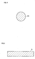
- the main body portion 3 is formed of an elongated object with a bar shape (non-plate shape). It is preferable that the transverse cross sectional shape (which is a YZ-axis plane and a cross section perpendicular to a length direction) of the main body portion 3 is substantially a circular shape (refer to Fig. 4 ).
- the main body portion 3 includes a large-diameter portion 31 having a constant outer diameter from the proximal side to the distal side; a first tapered portion 32 of which the outer diameter is decreased toward the distal side; a middle-diameter portion 33 having a constant outer diameter; a second tapered portion 34 of which the outer diameter is decreased toward the distal side; and a small-diameter portion 35 having a constant outer diameter.
- Two tapered portions of the first tapered portion 32 and the second tapered portion 34 are described above as tapered portions formed between portions (between the large-diameter portion 31 and the middle-diameter portion 33, and between the middle-diameter portion 33 and the small-diameter portion 35) which have a constant diameter.
- the number of the tapered portions is not limited to two, and at least one tapered portion may be formed.
- a large-diameter portion 36 which has the same outer diameter as that of the large-diameter portion 31 and has a constituent material different from that of the large-diameter portion 31 may be joined to the large-diameter portion 31 in a joint portion (welded portion) 37.
- the joining method is not particularly limited, but examples thereof include butt resistance welding such as friction pressure welding, spot welding using a laser, or upset welding, and joining using a tubular joint member.
- the flat plate portion 5 provides flexibility to the wire 1 (core portion 2A) and is formed of an elongated plate-shaped flat plate having a rectangular shape in transverse cross section (refer to Fig. 5 ) so as to facilitate reshaping of a distal portion of the wire at the distal end.
- the flat plate portion 5 preferably has a plate length of 1 to 30 mm, a plate width of 0.1 to 0.5 mm, and a plate width of 0.01 to 0.06 mm.
- the plate width of the flat plate portion 5 may be increased or decreased toward the distal side, and the plate thickness may also be increased or decreased toward the distal side.
- the distal side of the flat plate portion 5 is fixed to the coil portion 6 using the fixation material (fixation portion) 72 or the like.
- the flat plate portion 5 is preferably produced together with the transition portion 4 to be described below by pressing the distal side of the bar-shaped main body portion 3, preferably the distal side of which the diameter is reduced, using a mold or the like. Note that since the transverse cross sectional shape of the flat plate portion 5 is produced through the pressing, both ends thereof are slightly rounded and have an approximately rectangular shape in transverse cross section. However, the roundness of the both ends are omitted in Fig. 5 for the convenience of description.
- the transition portion 4 is a portion which connects the main body portion 3 and the flat plate portion 5 and which is gradually changed from a circular shape in transverse cross section (refer to Fig. 4 ) to the rectangular shape in transverse cross section (refer to Fig. 5 ) from the proximal side toward the distal side.
- the length of the transition portion 4 is preferably 1 to 10 mm.
- the transition portion 4 has four slopes 4a, 4b, 4c, and 4d which are connected to surfaces of the flat plate portion 5. At least one of the groove portion 41 or the groove portion 42 extending in a direction different from the length direction is formed on at least one slope in the length direction. Note that the groove portion 42 may not be formed.
- the groove portions 41 and 42 are preferably produced by pressing a mold having a surface of a mold, in which convex portions with a shape similar to the groove portions 41 and 42 are formed, on the slope of the transition portion 4.
- the groove portion 41 is formed on the slope 4a on the same surface side as an upper surface 5a of the flat plate portion 5.
- the groove portion 41 may be formed on the slope 4b or the slopes 4c and 4d on the same surface sides as a lower surface 5b or side surfaces 5c and 5d of the flat plate portion 5.
- the groove portion 41 may be continuously formed on at least two slopes out of peripheral surfaces consisting of the slope 4a to the slope 4d.
- the direction in which the groove portion 41 is formed is not particularly limited, but is preferably a direction orthogonal to the length direction as shown in Fig. 3 .
- the groove portion 41 may be formed in a direction inclined to the direction orthogonal to the length direction at a predetermined angle.
- the planar shape of the groove portion 41 is preferably a linear shape as shown in Fig. 3 , but may be a polygonal line shape or a curved shape.
- the transverse cross sectional shape of the groove portion 41 formed in the transition portion 4 is an approximately semi-circular shape.
- the transverse cross sectional shape of the groove portion 41 may be other shapes, for example, an approximately U-shape, an approximately V-shape, or an approximately rectangular shape.
- the number of groove portions 41 is preferably 1 to 100.
- the groove width W1 of the groove portion 41 is preferably 0.001 to 3 mm.
- the groove depth D1 of the groove portion 41 is preferably 0.005 to 0.05 mm.
- the groove width W1 is preferably formed to be constant, but may be formed so as to be increased or decreased toward the distal side.
- the groove depth D1 is also preferably formed to be constant, but may be formed so as to be increased or decreased toward the distal side.
- An interval T1 of adjacent groove portions 41 is preferably 0.005 to 3 mm.
- the plurality of groove portions 41 are preferably formed at even intervals, but may be formed so that the interval T1 increases or decreases toward the distal side.
- the plurality of groove portions 41 may have an interval T1 of 0 mm, that is, may be continuously formed.
- the groove portions 41 which have been continuously formed may be formed in a part or all of the slopes 4a, 4b, 4c, and 4d of the transition portion 4.
- the groove portion 41 is formed on the slope 4a and the groove portion 42 is formed on the slope 4b on the same surface side as the lower surface 5b of the flat plate portion 5.
- the groove portion 41 and the groove portion 42 are mutually alternately disposed in the length direction of the transition portion 4.
- the groove portion 41 and the groove portion 42 may be disposed at the same position as each other.
- the groove portion 42 is formed on the slope 4a.
- the groove portion 41 is formed on one of the slopes 4c and 4d
- the groove portion 42 is formed on one of the slopes 4d or 4c which is on a side opposite to the slope on which the groove portion 41 is formed.
- the groove portions 41 are continuously formed on at least two slopes on the peripheral surface consisting of the slopes 4a to 4d
- the groove portions 42 may be disposed and formed alternately with the groove portion 41 on slopes on which the groove portion 41 has not been formed.
- the formation direction, the planar shape, the transverse cross-sectional shape, the number of grooves, the groove width, and the groove depth of the groove portion 42, and the interval between adjacent groove portions 42 are the same as those of the groove portion 41, and therefore, the description thereof will not be repeated.
- the formation direction or the like of the groove portion 42 is preferably the same as that of the groove portion 41, but may be different from that of the groove portion 41.
- the wire 1 of the present invention forming of the groove portions 41 and 42 suppresses great change in the transverse cross sectional shape from the transition portion 4 over the flat plate portion 5, and therefore, great change in the rigidity is also suppressed.
- the flat plate portion 5 is twisted when using the wire 1 or is buckled in the vicinity of a boundary between the transition portion 4 and the flat plate portion 5. Therefore, rotary torque of the main body portion 3 is effectively transmitted to the flat plate portion 5. Accordingly, it is possible to make the distal portion of the wire 1 face in intended direction. In addition, a pushing force of the main body portion 3 is effectively transmitted to the flat plate portion 5. As a result, excellent blood vessel followability, pushability, and trackability of the wire 1 are improved.
- the coil portion 6 is a coil which is disposed so as to cover the distal side of the core portion 2A and is obtained by forming strands in a spiral shape.
- the coil may be either a so-called densely wound coil in which adjacent strands are in contact with each other or a coil in which adjacent strands are separated from each other.
- the distal side of the coil portion 6 is fixed to the core portion 2A (flat plate portion 5) using the fixation material (fixation portion) 72 or the like.
- the materials constituting the strands are not particularly limited, but are preferably metal materials such as stainless steel or Pt-Ni alloy.
- the size of the coil portion 6 is not particularly limited, and varies depending on use purpose of the wire 1. In the wire 1 used for PTCA, it is preferable that the coil outer diameter of the coil portion 6 is 0.2 to 0.5 mm and the coil length is 10 to 1000 mm. The coil outer diameter is preferably constant in the length direction of the wire 1, but may be decreased toward the distal side of the wire 1.
- the coil portion 6 may be obtained by combining two or more metal materials.
- the coil portion 6 may include a first coil portion 61 formed of stainless steel strands on the proximal side; and a second coil portion 62 formed of Pt-Ni alloy strands as radiopaque materials on the distal side, and both coil portions 61 and 62 may be joined through welding, adhering, or the like in a boundary portion 63 between the first coil portion 61 and the second coil portion 62. Accordingly, it is easy for the distal side of the wire 1 to be visually checked under X-ray fluoroscopy.
- the core portion 2A and the coil portion 6 are fixed to each other in one site on the distal side, but the core portion 2A and the coil portion 6 are preferably fixed to each other in a plurality of sites.
- the distal side of the core portion 2A (flat plate portion 5) and the distal side of the coil portion 6 (second coil portion 62) are fixed to each other using the fixation material (fixation portion) 72; a site (the proximal side of the transition portion 4, the small-diameter portion 35, and the distal side of the second tapered portion 34) in the middle of the core portion 2A and a site (boundary portion 63) in the middle of the coil portion 6 are fixed to each other using a fixation material (fixation portion) 73; and a site (the proximal side of the middle-diameter portion 33 and the distal side of the first tapered portion 32) in the middle of the core portion 2A and the proximal side of the coil portion 6 (first coil portion 61) are fixed to each other using a fixation material (fixation portion) 71.
- fixation materials (fixation portions) 71, 72, and 73 are solder (brazing materials), adhesives, or the like. Note that, in the fixation method of the core portion 2A and the coil portion 6, it is not limited to use the fixation materials 71, 72, and 73, and the fixation portions 71, 72, and 73 may be formed through welding.
- the wire 1 preferably includes a resin covering portion 8 which is formed so as to cover at least the surface of the coil portion 6 on the distal side.
- the resin covering portion 8 preferably covers a part of the surface of the wire or the entirety of the surface of the wire, that is, the entire surface of the second coil portion 62, the entire surface of the coil portion 6 (the first coil portion 61, the boundary portion 63, and the second coil portion 62), or the entire surface of a site on the proximal side of the coil portion 6 and the core portion 2A.
- the resin covering portion 8 is preferably made of resin materials such as a fluorine resin, a maleic anhydride polymeric material, and polyurethane.
- the thickness of the resin covering portion 8 is preferably 0.001 to 0.05 mm. Since the wire 1 is covered by such a resin covering portion 8, the frictional resistance (sliding resistance) of the wire 1 is decreased, and the operability in a blood vessel is improved.
- a core portion 2B (refer to Figs. 6 and 7 ) is used instead of the core portion 2A (refer to Fig. 1 ) of the first embodiment. Therefore, at least one of a groove portion 51 or a groove portion 52 extending in a direction different from a length direction is formed in a flat plate portion 5 in the length direction in addition to forming the groove portion 41 or the groove portion 41 and the groove portion 42 in the transition portion 4. In addition, the groove portion 52 may not be formed.
- the groove portions 51 and 52 are preferably formed by pressing a mold having a surface of a mold, in which convex portions with a shape similar to the groove portions 51 and 52 are formed, on the surface of the flat plate portion 5. Note that the configuration of the first embodiment other than the groove portions 51 and 52 are the same as described above, and therefore, only the groove portions 51 and 52 will be described and the description of other portions will not be repeated.
- the groove portion 51 is formed on an upper surface 5a of the flat plate portion 5.
- the groove portion 51 may be formed on a lower surface 5b of the flat plate portion 5.
- the upper surface 5a and the lower surface 5b are surfaces which become an inner peripheral surface and an outer peripheral surface when a distal portion of the wire is curved.
- the direction in which the groove portion 51 is formed is not particularly limited, but is preferably a plate width direction (a direction orthogonal to the length direction) as shown in Fig. 7 .
- the groove portion 51 may be formed in an oblique line shape in a direction inclined to the plate width direction at a predetermined angle.
- the oblique line-shaped groove portion 51 is formed in this manner, transmission of rotary torque from a proximal side to a distal side varies depending on the rotational direction of the wire 1 (core portion 2B), and the rotary torque is easily transmitted in the rotational direction opposite to the inclination direction of the oblique line-shaped groove portion 51. As a result, the blood vessel followability of the wire 1 is further improved.
- the planar shape of the groove portion 51 is preferably a linear shape as shown in Fig. 7 , but may be a polygonal line shape or a curved shape.
- the transverse cross sectional shape of the groove portion 51 formed in the flat plate portion 5 is an approximately semi-circular shape.
- the transverse cross sectional shape of the groove portion 51 may be other shapes, for example, an approximately U-shape, an approximately V-shape, or an approximately rectangular shape.
- the number of groove portions 51 is preferably 1 to 500.
- the groove width W2 of the groove portion 51 is preferably 0.06 to 0.5 mm.
- the groove depth D2 of the groove portion 51 is preferably 0.001 to 0.03 mm.
- the groove width W2 is preferably formed to be constant, but may be formed so as to be increased or decreased toward the distal side.
- the groove depth D2 is also preferably formed to be constant, but may be formed so as to be increased or decreased toward the distal side.
- An interval T2 of adjacent groove portions 51 is preferably 0.1 to 2 mm.
- the plurality of groove portions 51 are preferably formed at even intervals, but may be formed so that the interval T2 increases or decreases toward the distal side.
- the plurality of groove portions 51 may have an interval T2 of 0 mm, that is, may be continuously formed.
- the groove portions 51 which have been continuously formed may be formed in a part or all of the upper surface 5a or the lower surface 5b of the flat plate portion 5.
- the groove portion 51 is formed on the upper surface 5a and the groove portion 52 is formed on the lower surface 5b of the flat plate portion 5.
- the groove portion 51 and the groove portion 52 are mutually alternately disposed in the length direction of the flat plate portion 5.
- the groove portion 51 and the groove portion 52 may be disposed at the same position as each other.
- the groove portion 52 is formed on the upper surface 5a.
- the formation direction, the planar shape, the transverse cross-sectional shape, the number of grooves, the groove width, and the groove depth of the groove portion 52, and the interval between adjacent groove portions 52 are the same as those of the groove portion 51, and therefore, the description thereof will not be repeated.
- the formation direction or the like of the groove portion 52 is preferably the same as that of the groove portion 51, but may be different from that of the groove portion 51.
- the rigidity of the flat plate portion 5 is further decreased by forming the groove portions 51 and 52. Therefore, the flexibility of the distal portion of the guide wire is further improved and the risk of perforating a blood vessel is reduced. Thus, the safety is improved. Accordingly, the blood vessel followability of the guide wire is further improved.
- Modification examples of the second embodiment of the guide wire of the present invention include an example in which the core portion 2B and the coil portion 6 are fixed to each other in a plurality of sites and an example in which the surface of the wire is covered with the resin covering portion 8, similarly to the first embodiment.
- a guide wire 1 includes a resin covering portion 9 instead of the coil portion 6 in the first embodiment which includes the core portion 2A.
- the guide wire 1 may include the resin covering portion 9 instead of the coil portion 6 in the second embodiment which includes the core portion 2B (refer to Fig. 6 ).
- the resin covering portion 9 is formed so as to cover a distal side of the core portion 2A or the core portion 2B and is made of a resin material.
- the resin material include a fluorine resin or polyurethane, and polyurethane is preferable. It is preferable that the resin covering portion 9 is formed such that the thickness thereof on the distal side is thicker than that on the proximal side. The thickness thereof is preferably 10 to 400 ⁇ m. In addition, the resin covering portion 9 is preferably formed such that the distal side thereof is rounded.
- a distal end of the guide wire is inserted into a femoral artery in a state protruding from a distal end of a guiding catheter, through a Seldinger technique, and is inserted into a right coronary artery via an aorta, an aortic arch, and a right coronary artery orifice. Only the guide wire is made to pass a stenosed site of a blood vessel by being further advanced within the right coronary artery while leaving the guiding catheter at a position of the right coronary artery orifice. Then, the distal end of the guide wire stops at a position beyond the stenosed site of the blood vessel. Accordingly, the passage of a balloon catheter for widening the stenosed site is secured.
- a distal end of the balloon catheter which has been inserted from a proximal side of the guide wire, is made to protrude from the distal end of the guiding catheter, and is inserted into the right coronary artery from the right coronary artery orifice by being further advanced along the guide wire.
- the distal end of the balloon catheter stops at a position at which a balloon of the balloon catheter reaches a position of the stenosed site of the blood vessel.
- the stenosed site of the blood vessel is widened by dilating the balloon after injecting a fluid for dilating a balloon into the balloon catheter from the proximal side thereof.
- deposits such as cholesterol which have been adhered to and deposited in the stenosed site of the blood vessel are physically widened, and therefore, interruption of blood flow is resolved.
- the fluid for dilating a balloon is removed from the balloon to deflate the balloon.
- the balloon catheter, the guide wire, and the guiding catheter are removed from the blood vessel by moving the balloon catheter in the proximal direction along with the guide wire. Accordingly, the procedure of PTCA finishes.
Landscapes
- Health & Medical Sciences (AREA)
- Life Sciences & Earth Sciences (AREA)
- Biophysics (AREA)
- Pulmonology (AREA)
- Engineering & Computer Science (AREA)
- Anesthesiology (AREA)
- Biomedical Technology (AREA)
- Heart & Thoracic Surgery (AREA)
- Hematology (AREA)
- Animal Behavior & Ethology (AREA)
- General Health & Medical Sciences (AREA)
- Public Health (AREA)
- Veterinary Medicine (AREA)
- Media Introduction/Drainage Providing Device (AREA)
Abstract
Description
- The present invention relates to a guide wire used when guiding a catheter into a lumen in a living body, in particular, a blood vessel.
- The guidewire is used when guiding a catheter which is used for treatment of a site in which it is difficult to perform a surgical operation, for example, percutaneous transluminal coronary angioplasty (PTCA) or treatment which is aimed to be less invasive to the human body, or used in tests such as cardioangiography, into a blood vessel. PTCA is a treatment method for dilating a stenosed site of a coronary artery with a balloon or the like to secure a blood flow path.
- In PTCA, a balloon catheter is guided to a stenosed site by inserting a guide wire into the vicinity of the stenosed site of a blood vessel in a state in which a distal portion of the guide wire protrudes from a distal portion of the balloon catheter. At that time, it is necessary for the guide wire to select and pass through a meandering or bifurcated blood vessel, a stenosed blood vessel, or the like. In addition, it is necessary to widen or penetrate deposits such as cholesterol constituting the stenosed site using a pushing force of the guide wire in the stenosed site. Accordingly, excellent flexibility (blood vessel followability) for following the shape of a blood vessel and for preventing damage to a blood vessel wall, and excellent pushing performance (pushability) which ensure effective transmission of a pushing force from the operator's hand side (proximal portion) to a distal portion are required for the guide wire used for PTCA.
- In addition, in PTCA, in some cases, reshaping at a distal end is performed before inserting the guide wire into the blood vessel in order to make the guide wire follow the bent and bifurcated blood vessel. Specifically, a surgeon performs the reshaping by bending the distal portion of the guide wire into a predetermined shape (for example, J shape) using fingers in accordance with the shape of the bifurcated blood vessel or the like. Accordingly, it is necessary for the guide wire to easily perform such reshaping at a distal end.
- In the related art, a guide wire including the following configuration has been proposed in Patent Literature 1 as a guide wire used for PTCA. The guide wire in Patent Literature 1 includes a core portion formed of an elongated object; and a coil which is provided so as to cover a distal side of the core portion. The core portion has a flat plate portion, which is formed to have a plate width equal to or more than twice the plate height (plate thickness), on the distal side.
- Patent Literature 1: International Publication No.
2009/126656 - In the guide wire of Patent Literature 1, the distal portion of the guide wire becomes flexible because a flat plate portion with a thin plate thickness is provided on the distal side of the core portion, and it is expected to improve safety and blood vessel followability to some degree. However, the guide wire in Patent Literature 1 includes a round rod-like main body portion which is formed on a proximal side and has a circular shape in transverse cross section; a flat plate portion which is formed on a distal side and has a rectangular shape in transverse cross section; and a transition portion which connects the main body portion and the flat plate portion. Accordingly, in the guide wire of Patent Literature 1, the transverse cross sectional shape greatly changes from the transition portion over the flat plate portion. Therefore, the physical properties (in particular, rigidity) also greatly change from the transition portion over the flat plate portion.
- In such a guide wire, when the proximal portion of the guide wire is rotated in order to make the guide wire pass a meandering or bifurcated blood vessel, the flat plate portion is twisted or is buckled in the vicinity of a boundary between the transition portion and the flat plate portion. As a result, rotary torque at the proximal portion of the guide wire is not effectively transmitted from the proximal portion to the distal portion. Therefore, there is a problem in that the distal portion of the guide wire does not face an intended direction and blood vessel followability of the guide wire is decreased. In addition, there is a problem in that torquability is decreased due to twisting of the flat plate portion when the proximal portion of the guide wire is rotated in order to advance the guide wire in a stenosed site, or that pushability and trackability (properties of transmitting a rotational force, which is applied to the guide wire at the proximal portion, to the distal portion) of the guide wire without effective transmission of a pushing force of the proximal portion of the guide wire to the distal portion due to buckling of the flat plate portion in the vicinity of a boundary between the transition portion and the flat plate portion.
- The present invention has been devised in order to solve such problems. Therefore, an object of the present invention is to provide a guide wire having excellent blood vessel followability, pushability, and trackability.
- In order to solve the problems, there is provided a guide wire according to the present invention which includes a core portion formed of an elongated object having flexibility, in which the core portion includes a main body portion formed on a proximal side, a flat plate portion formed on a distal side, and a transition portion which connects the main body portion and the flat plate portion, and in which at least one groove portion extending in a direction different from a length direction is formed on a slope of the transition portion in the length direction.
- In addition, it is preferable that the guide wire according to the present invention includes a coil portion which is disposed so as to cover the distal side of the core portion and is obtained by forming strands in a spiral shape, and the core portion and the coil portion are fixed to each other on the distal side. In addition, it is preferable that the guide wire according to the present invention includes a resin covering portion which is formed so as to cover the distal side of the core portion and is made of a resin material.
- According to the configuration, a portion with a thin plate thickness is disposed on the distal side of the guide wire because the flat plate portion is provided on the distal side of the core portion. Therefore, rigidity at a distal portion of the guide wire is decreased and flexibility of the guide wire at the distal portion is improved. In addition, since the rigidity at the distal portion of the guide wire is decreased, reshaping of the distal portion of the guide wire is easily performed in accordance with the shape of a bifurcated blood vessel or the like. In addition, significant change in the transverse cross sectional shape and significant change in the rigidity from the transition portion over the flat plate portion are prevented because at least one groove portion is formed in the transition portion which connects the main body portion and the flat plate portion of the core portion. Accordingly, twisting of the flat plate portion or buckling in the vicinity of a boundary between the transition portion and the flat plate portion is suppressed when the guide wire passes a meandering or bifurcated blood vessel or when the guide wire advances in a stenosed site. As a result, it is possible to effectively transmit rotary torque of a proximal portion of the guide wire to the distal portion, and therefore, it is possible to make the distal portion of the guide wire face an intended direction. In addition, it is possible to effectively transmit pushing force of the proximal portion of the guide wire to the distal portion.
- In addition, in the guide wire according to the present invention, it is preferable that at least one groove portion extending in the direction different from the length direction is formed on at least an upper surface or a lower surface of the flat plate portion in the length direction.
- According to the configuration, the rigidity of the flat plate portion is further decreased because the groove portion is formed in the flat plate portion. Therefore, the rigidity at the distal portion of the guide wire at which the flat plate portion is disposed is decreased and the flexibility of the guide wire at the distal portion is further improved.
- According to the guide wire of the present invention, the flexibility of the guide wire on the distal side is improved and the change in the rigidity of a distal flexible portion is decreased. Therefore blood vessel followability of the guide wire becomes excellent. In addition, since the buckling of the core portion or the like is suppressed, it is possible to effectively transmit rotary torque or pushing force at the proximal portion of the guide wire to the distal portion. Therefore, blood vessel followability, pushability, and trackability of the guide wire become excellent.
-
- [
Fig. 1] Fig. 1 is a partial longitudinal sectional view showing a first embodiment of a guide wire of the present invention. - [
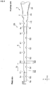
Fig. 2] Fig. 2 is a side view of a core portion of the guide wire on a distal side shown inFig. 1 . - [
Fig. 3] Fig. 3 is a plan view of the core portion of the guide wire on the distal side shown inFig. 1 . - [
Fig. 4] Fig. 4 is an end surface view of the core portion taken along line A-A shown inFig. 3 . - [
Fig. 5] Fig. 5 is an end surface view of the core portion taken along line B-B shown inFig. 3 . - [
Fig. 6] Fig. 6 is a side view of a core portion on a distal side which shows a second embodiment of a guide wire of the present invention. - [
Fig. 7] Fig. 7 is a plan view of the core portion on the distal side shown inFig. 6 . - [
Fig. 8] Fig. 8 is a partial longitudinal sectional view showing a third embodiment of a guide wire of the present invention on a distal side of the wire. - A first embodiment of a guide wire according to the present invention will be described in detail while referring to drawings. Note that, in the present invention, a distal side refers to a side on which a guide wire is inserted into a blood vessel, and a proximal side refers to a side on which a surgeon or the like operates the guide wire.
- As shown in
Fig. 1 , a guide wire (hereinafter, referred to as a wire) 1 is an elongated object including acore portion 2A which includes amain body portion 3, atransition portion 4, and aflat plate portion 5.Groove portions transition portion 4. The total length of the wire 1 is not particularly limited, and is preferably, for example, 200 to 5000 mm. In addition, it is preferable that the wire 1 includes acoil portion 6 disposed so as to cover a distal side of thecore portion 2A, and in which thecore portion 2A and thecoil portion 6 are fixed to each other on the distal side. As the fixing method, a fixation material (fixation portion) 72 such as solder (brazing material) or an adhesive material is preferably used for the fixing, and thefixation portion 72 may be formed through welding. Hereinafter, each configuration will be described. - As shown in
Figs. 1 to 3 , thecore portion 2A is formed of an elongated object having flexibility. Thecore portion 2A is preferably made of an elastic metal material such as Ni-Ti alloy or stainless steel in consideration of the flexibility and the strength of the wire 1. Thecore portion 2A sequentially includes themain body portion 3, thetransition portion 4, and theflat plate portion 5 from a proximal side to the distal side, and at least one of thegroove portion 41 or thegroove portion 42 is formed in thetransition portion 4. Note that thegroove portion 42 may not be formed. - As shown in
Figs. 1 to 3 , themain body portion 3 is formed of an elongated object with a bar shape (non-plate shape). It is preferable that the transverse cross sectional shape (which is a YZ-axis plane and a cross section perpendicular to a length direction) of themain body portion 3 is substantially a circular shape (refer toFig. 4 ). In addition, it is preferable that themain body portion 3 includes a large-diameter portion 31 having a constant outer diameter from the proximal side to the distal side; a first taperedportion 32 of which the outer diameter is decreased toward the distal side; a middle-diameter portion 33 having a constant outer diameter; a second taperedportion 34 of which the outer diameter is decreased toward the distal side; and a small-diameter portion 35 having a constant outer diameter. - Two tapered portions of the first tapered
portion 32 and the second taperedportion 34 are described above as tapered portions formed between portions (between the large-diameter portion 31 and the middle-diameter portion 33, and between the middle-diameter portion 33 and the small-diameter portion 35) which have a constant diameter. However, the number of the tapered portions is not limited to two, and at least one tapered portion may be formed. In addition, a large-diameter portion 36 which has the same outer diameter as that of the large-diameter portion 31 and has a constituent material different from that of the large-diameter portion 31 may be joined to the large-diameter portion 31 in a joint portion (welded portion) 37. The joining method is not particularly limited, but examples thereof include butt resistance welding such as friction pressure welding, spot welding using a laser, or upset welding, and joining using a tubular joint member. - As shown in
Figs. 1 to 3 , theflat plate portion 5 provides flexibility to the wire 1 (core portion 2A) and is formed of an elongated plate-shaped flat plate having a rectangular shape in transverse cross section (refer toFig. 5 ) so as to facilitate reshaping of a distal portion of the wire at the distal end. Theflat plate portion 5 preferably has a plate length of 1 to 30 mm, a plate width of 0.1 to 0.5 mm, and a plate width of 0.01 to 0.06 mm. In addition, the plate width of theflat plate portion 5 may be increased or decreased toward the distal side, and the plate thickness may also be increased or decreased toward the distal side. - In addition, the distal side of the
flat plate portion 5 is fixed to thecoil portion 6 using the fixation material (fixation portion) 72 or the like. In addition, theflat plate portion 5 is preferably produced together with thetransition portion 4 to be described below by pressing the distal side of the bar-shapedmain body portion 3, preferably the distal side of which the diameter is reduced, using a mold or the like. Note that since the transverse cross sectional shape of theflat plate portion 5 is produced through the pressing, both ends thereof are slightly rounded and have an approximately rectangular shape in transverse cross section. However, the roundness of the both ends are omitted inFig. 5 for the convenience of description. - As shown in
Figs. 2 and3 , thetransition portion 4 is a portion which connects themain body portion 3 and theflat plate portion 5 and which is gradually changed from a circular shape in transverse cross section (refer toFig. 4 ) to the rectangular shape in transverse cross section (refer toFig. 5 ) from the proximal side toward the distal side. The length of thetransition portion 4 is preferably 1 to 10 mm. In addition, thetransition portion 4 has fourslopes flat plate portion 5. At least one of thegroove portion 41 or thegroove portion 42 extending in a direction different from the length direction is formed on at least one slope in the length direction. Note that thegroove portion 42 may not be formed. Thegroove portions groove portions transition portion 4. - As shown in
Figs. 2 and3 , thegroove portion 41 is formed on theslope 4a on the same surface side as anupper surface 5a of theflat plate portion 5. Note that, although not shown in the drawing, thegroove portion 41 may be formed on theslope 4b or theslopes lower surface 5b orside surfaces flat plate portion 5. Although not shown in the drawing, thegroove portion 41 may be continuously formed on at least two slopes out of peripheral surfaces consisting of theslope 4a to theslope 4d. - The direction in which the
groove portion 41 is formed is not particularly limited, but is preferably a direction orthogonal to the length direction as shown inFig. 3 . Note that, although not shown in the drawing, thegroove portion 41 may be formed in a direction inclined to the direction orthogonal to the length direction at a predetermined angle. Furthermore, the planar shape of thegroove portion 41 is preferably a linear shape as shown inFig. 3 , but may be a polygonal line shape or a curved shape. - It is preferable that the transverse cross sectional shape of the
groove portion 41 formed in thetransition portion 4 is an approximately semi-circular shape. However, the transverse cross sectional shape of thegroove portion 41 may be other shapes, for example, an approximately U-shape, an approximately V-shape, or an approximately rectangular shape. The number ofgroove portions 41 is preferably 1 to 100. The groove width W1 of thegroove portion 41 is preferably 0.001 to 3 mm. The groove depth D1 of thegroove portion 41 is preferably 0.005 to 0.05 mm. In addition, in a case of forming a plurality ofgroove portions 41, the groove width W1 is preferably formed to be constant, but may be formed so as to be increased or decreased toward the distal side. The groove depth D1 is also preferably formed to be constant, but may be formed so as to be increased or decreased toward the distal side. - An interval T1 of
adjacent groove portions 41 is preferably 0.005 to 3 mm. The plurality ofgroove portions 41 are preferably formed at even intervals, but may be formed so that the interval T1 increases or decreases toward the distal side. In addition, the plurality ofgroove portions 41 may have an interval T1 of 0 mm, that is, may be continuously formed. Furthermore, thegroove portions 41 which have been continuously formed may be formed in a part or all of theslopes transition portion 4. - As shown in
Figs. 2 and3 , in thetransition portion 4, it is preferable that thegroove portion 41 is formed on theslope 4a and thegroove portion 42 is formed on theslope 4b on the same surface side as thelower surface 5b of theflat plate portion 5. In addition, it is preferable that thegroove portion 41 and thegroove portion 42 are mutually alternately disposed in the length direction of thetransition portion 4. However, thegroove portion 41 and thegroove portion 42 may be disposed at the same position as each other. In addition, although not shown in the drawing, in a case where thegroove portion 41 is formed on theslope 4b, thegroove portion 42 is formed on theslope 4a. In addition, although not shown in the drawing, in a case where thegroove portion 41 is formed on one of theslopes groove portion 42 is formed on one of theslopes groove portion 41 is formed. - Although not shown in the drawing, in a case where the
groove portions 41 are continuously formed on at least two slopes on the peripheral surface consisting of theslopes 4a to 4d, thegroove portions 42 may be disposed and formed alternately with thegroove portion 41 on slopes on which thegroove portion 41 has not been formed. - The formation direction, the planar shape, the transverse cross-sectional shape, the number of grooves, the groove width, and the groove depth of the
groove portion 42, and the interval betweenadjacent groove portions 42 are the same as those of thegroove portion 41, and therefore, the description thereof will not be repeated. In addition, the formation direction or the like of thegroove portion 42 is preferably the same as that of thegroove portion 41, but may be different from that of thegroove portion 41. - Although not shown in the drawing, in a case where a plurality of
groove portions 41 are formed, other groove portions which communicate with two or morearbitrary groove portions 41 in the length direction of thetransition portion 4 may be formed. In addition, even in a case where a plurality ofgroove portions 42 are formed, other groove portions which communicate with two or morearbitrary groove portions 42 in the length direction of thetransition portion 4 may also be formed. - In the wire 1 of the present invention, forming of the
groove portions transition portion 4 over theflat plate portion 5, and therefore, great change in the rigidity is also suppressed. As a result, there is no case where theflat plate portion 5 is twisted when using the wire 1 or is buckled in the vicinity of a boundary between thetransition portion 4 and theflat plate portion 5. Therefore, rotary torque of themain body portion 3 is effectively transmitted to theflat plate portion 5. Accordingly, it is possible to make the distal portion of the wire 1 face in intended direction. In addition, a pushing force of themain body portion 3 is effectively transmitted to theflat plate portion 5. As a result, excellent blood vessel followability, pushability, and trackability of the wire 1 are improved. - As shown in
Fig. 1 , thecoil portion 6 is a coil which is disposed so as to cover the distal side of thecore portion 2A and is obtained by forming strands in a spiral shape. The coil may be either a so-called densely wound coil in which adjacent strands are in contact with each other or a coil in which adjacent strands are separated from each other. In addition, the distal side of thecoil portion 6 is fixed to thecore portion 2A (flat plate portion 5) using the fixation material (fixation portion) 72 or the like. - The materials constituting the strands are not particularly limited, but are preferably metal materials such as stainless steel or Pt-Ni alloy. In addition, the size of the
coil portion 6 is not particularly limited, and varies depending on use purpose of the wire 1. In the wire 1 used for PTCA, it is preferable that the coil outer diameter of thecoil portion 6 is 0.2 to 0.5 mm and the coil length is 10 to 1000 mm. The coil outer diameter is preferably constant in the length direction of the wire 1, but may be decreased toward the distal side of the wire 1. - The
coil portion 6 may be obtained by combining two or more metal materials. For example, thecoil portion 6 may include afirst coil portion 61 formed of stainless steel strands on the proximal side; and asecond coil portion 62 formed of Pt-Ni alloy strands as radiopaque materials on the distal side, and bothcoil portions boundary portion 63 between thefirst coil portion 61 and thesecond coil portion 62. Accordingly, it is easy for the distal side of the wire 1 to be visually checked under X-ray fluoroscopy. - Next, a modification example of the first embodiment of the wire 1 of the present invention will be described.
- As shown in
Fig. 1 , in the wire 1, it is sufficient for thecore portion 2A and thecoil portion 6 to be fixed to each other in one site on the distal side, but thecore portion 2A and thecoil portion 6 are preferably fixed to each other in a plurality of sites. - For example, as shown in
Fig. 1 , in the wire 1, the distal side of thecore portion 2A (flat plate portion 5) and the distal side of the coil portion 6 (second coil portion 62) are fixed to each other using the fixation material (fixation portion) 72; a site (the proximal side of thetransition portion 4, the small-diameter portion 35, and the distal side of the second tapered portion 34) in the middle of thecore portion 2A and a site (boundary portion 63) in the middle of thecoil portion 6 are fixed to each other using a fixation material (fixation portion) 73; and a site (the proximal side of the middle-diameter portion 33 and the distal side of the first tapered portion 32) in the middle of thecore portion 2A and the proximal side of the coil portion 6 (first coil portion 61) are fixed to each other using a fixation material (fixation portion) 71. - Here, the fixation materials (fixation portions) 71, 72, and 73 are solder (brazing materials), adhesives, or the like. Note that, in the fixation method of the
core portion 2A and thecoil portion 6, it is not limited to use thefixation materials fixation portions - As shown in
Fig. 1 , the wire 1 preferably includes aresin covering portion 8 which is formed so as to cover at least the surface of thecoil portion 6 on the distal side. - Specifically, the
resin covering portion 8 preferably covers a part of the surface of the wire or the entirety of the surface of the wire, that is, the entire surface of thesecond coil portion 62, the entire surface of the coil portion 6 (thefirst coil portion 61, theboundary portion 63, and the second coil portion 62), or the entire surface of a site on the proximal side of thecoil portion 6 and thecore portion 2A. - The
resin covering portion 8 is preferably made of resin materials such as a fluorine resin, a maleic anhydride polymeric material, and polyurethane. In addition, the thickness of theresin covering portion 8 is preferably 0.001 to 0.05 mm. Since the wire 1 is covered by such aresin covering portion 8, the frictional resistance (sliding resistance) of the wire 1 is decreased, and the operability in a blood vessel is improved. - Next, a second embodiment of a guide wire according to the present invention will be described.
- In the guide wire, a
core portion 2B (refer toFigs. 6 and7 ) is used instead of thecore portion 2A (refer toFig. 1 ) of the first embodiment. Therefore, at least one of agroove portion 51 or agroove portion 52 extending in a direction different from a length direction is formed in aflat plate portion 5 in the length direction in addition to forming thegroove portion 41 or thegroove portion 41 and thegroove portion 42 in thetransition portion 4. In addition, thegroove portion 52 may not be formed. Thegroove portions groove portions flat plate portion 5. Note that the configuration of the first embodiment other than thegroove portions groove portions - As shown in
Figs. 6 and7 , thegroove portion 51 is formed on anupper surface 5a of theflat plate portion 5. Note that, although not shown in the drawing, thegroove portion 51 may be formed on alower surface 5b of theflat plate portion 5. Here, theupper surface 5a and thelower surface 5b are surfaces which become an inner peripheral surface and an outer peripheral surface when a distal portion of the wire is curved. In addition, the direction in which thegroove portion 51 is formed is not particularly limited, but is preferably a plate width direction (a direction orthogonal to the length direction) as shown inFig. 7 . Note that, although not shown in the drawing, thegroove portion 51 may be formed in an oblique line shape in a direction inclined to the plate width direction at a predetermined angle. Since the oblique line-shapedgroove portion 51 is formed in this manner, transmission of rotary torque from a proximal side to a distal side varies depending on the rotational direction of the wire 1 (core portion 2B), and the rotary torque is easily transmitted in the rotational direction opposite to the inclination direction of the oblique line-shapedgroove portion 51. As a result, the blood vessel followability of the wire 1 is further improved. Furthermore, the planar shape of thegroove portion 51 is preferably a linear shape as shown inFig. 7 , but may be a polygonal line shape or a curved shape. - It is preferable that the transverse cross sectional shape of the
groove portion 51 formed in theflat plate portion 5 is an approximately semi-circular shape. However, the transverse cross sectional shape of thegroove portion 51 may be other shapes, for example, an approximately U-shape, an approximately V-shape, or an approximately rectangular shape. The number ofgroove portions 51 is preferably 1 to 500. The groove width W2 of thegroove portion 51 is preferably 0.06 to 0.5 mm. The groove depth D2 of thegroove portion 51 is preferably 0.001 to 0.03 mm. In addition, in a case of forming a plurality ofgroove portions 51, the groove width W2 is preferably formed to be constant, but may be formed so as to be increased or decreased toward the distal side. The groove depth D2 is also preferably formed to be constant, but may be formed so as to be increased or decreased toward the distal side. - An interval T2 of
adjacent groove portions 51 is preferably 0.1 to 2 mm. The plurality ofgroove portions 51 are preferably formed at even intervals, but may be formed so that the interval T2 increases or decreases toward the distal side. In addition, the plurality ofgroove portions 51 may have an interval T2 of 0 mm, that is, may be continuously formed. Furthermore, thegroove portions 51 which have been continuously formed may be formed in a part or all of theupper surface 5a or thelower surface 5b of theflat plate portion 5. - As shown in
Figs. 6 and7 , in theflat plate portion 5, it is preferable that thegroove portion 51 is formed on theupper surface 5a and thegroove portion 52 is formed on thelower surface 5b of theflat plate portion 5. In addition, it is preferable that thegroove portion 51 and thegroove portion 52 are mutually alternately disposed in the length direction of theflat plate portion 5. However, thegroove portion 51 and thegroove portion 52 may be disposed at the same position as each other. In addition, although not shown in the drawing, in a case where thegroove portion 51 is formed on thelower surface 5b, thegroove portion 52 is formed on theupper surface 5a. - The formation direction, the planar shape, the transverse cross-sectional shape, the number of grooves, the groove width, and the groove depth of the
groove portion 52, and the interval betweenadjacent groove portions 52 are the same as those of thegroove portion 51, and therefore, the description thereof will not be repeated. In addition, the formation direction or the like of thegroove portion 52 is preferably the same as that of thegroove portion 51, but may be different from that of thegroove portion 51. - Although not shown in the drawing, in a case where a plurality of
groove portions 51 are formed, other groove portions which communicate with two or morearbitrary groove portions 51 in the length direction of theflat plate portion 5 may be formed. In addition, even in a case where a plurality ofgroove portions 52 are formed, other groove portions which communicate with two or morearbitrary groove portions 52 in the length direction of theflat plate portion 5 may also be formed. - In the guide wire of the present invention, the rigidity of the
flat plate portion 5 is further decreased by forming thegroove portions - Modification examples of the second embodiment of the guide wire of the present invention include an example in which the
core portion 2B and thecoil portion 6 are fixed to each other in a plurality of sites and an example in which the surface of the wire is covered with theresin covering portion 8, similarly to the first embodiment. - Next, a third embodiment of a guide wire of the present invention will be described.
- As shown in
Fig. 8 , a guide wire 1 includes aresin covering portion 9 instead of thecoil portion 6 in the first embodiment which includes thecore portion 2A. In addition, although not shown in the drawing, the guide wire 1 may include theresin covering portion 9 instead of thecoil portion 6 in the second embodiment which includes thecore portion 2B (refer toFig. 6 ). - Note that the configuration of the first embodiment or the second embodiment other than the
resin covering portion 9 is the same as described above. Therefore, only theresin covering portion 9 will be described and the description of other portions will not be repeated. - The
resin covering portion 9 is formed so as to cover a distal side of thecore portion 2A or thecore portion 2B and is made of a resin material. Examples of the resin material include a fluorine resin or polyurethane, and polyurethane is preferable. It is preferable that theresin covering portion 9 is formed such that the thickness thereof on the distal side is thicker than that on the proximal side. The thickness thereof is preferably 10 to 400 µm. In addition, theresin covering portion 9 is preferably formed such that the distal side thereof is rounded. - Since such a
resin covering portion 9 is provided, it is prevented that thecore portion 2A or thecore portion 2B damage a blood vessel wall when using the guide wire 1. Therefore, the safety is improved. In addition, the frictional resistance (sliding resistance) is decreased in the guide wire 1, and therefore, the operability within a blood vessel is also improved. - Next, a method for using the guide wire of the present invention will be described by taking PTCA for an example.
- A distal end of the guide wire is inserted into a femoral artery in a state protruding from a distal end of a guiding catheter, through a Seldinger technique, and is inserted into a right coronary artery via an aorta, an aortic arch, and a right coronary artery orifice. Only the guide wire is made to pass a stenosed site of a blood vessel by being further advanced within the right coronary artery while leaving the guiding catheter at a position of the right coronary artery orifice. Then, the distal end of the guide wire stops at a position beyond the stenosed site of the blood vessel. Accordingly, the passage of a balloon catheter for widening the stenosed site is secured.
- Next, a distal end of the balloon catheter, which has been inserted from a proximal side of the guide wire, is made to protrude from the distal end of the guiding catheter, and is inserted into the right coronary artery from the right coronary artery orifice by being further advanced along the guide wire. The distal end of the balloon catheter stops at a position at which a balloon of the balloon catheter reaches a position of the stenosed site of the blood vessel.
- Next, the stenosed site of the blood vessel is widened by dilating the balloon after injecting a fluid for dilating a balloon into the balloon catheter from the proximal side thereof. By doing this, deposits such as cholesterol which have been adhered to and deposited in the stenosed site of the blood vessel are physically widened, and therefore, interruption of blood flow is resolved.
- The fluid for dilating a balloon is removed from the balloon to deflate the balloon. Next, the balloon catheter, the guide wire, and the guiding catheter are removed from the blood vessel by moving the balloon catheter in the proximal direction along with the guide wire. Accordingly, the procedure of PTCA finishes.
-
- 1: guide wire (wire)
- 2A, 2B: core portion
- 3: main body portion
- 4: transition portion
- 41, 42: groove portion
- 5: flat plate portion
- 51, 52: groove portion
- 6: coil portion
- 8, 9: resin covering portion
Claims (4)
- A guide wire comprising a core portion formed of an elongated object having flexibility,
wherein the core portion includes a main body portion formed on a proximal side, a flat plate portion formed on a distal side, and a transition portion which connects the main body portion and the flat plate portion, and
wherein at least one groove portion extending in a direction different from a length direction is formed on a slope of the transition portion in the length direction. - The guide wire according to claim 1,
wherein the guide wire includes a coil portion which is disposed so as to cover the distal side of the core portion and is obtained by forming strands in a spiral shape, and the core portion and the coil portion are fixed to each other on the distal side. - The guide wire according to claim 1,
wherein the guide wire includes a resin covering portion which is formed so as to cover the distal side of the core portion and is made of a resin material. - The guide wire according to any one of claims 1 to 3,
wherein at least one groove portion extending in the direction different from the length direction is formed on at least an upper surface or a lower surface of the flat plate portion in the length direction.
Applications Claiming Priority (2)
| Application Number | Priority Date | Filing Date | Title |
|---|---|---|---|
| JP2014196648 | 2014-09-26 | ||
| PCT/JP2015/074302 WO2016047364A1 (en) | 2014-09-26 | 2015-08-27 | Guide wire |
Publications (3)
| Publication Number | Publication Date |
|---|---|
| EP3199198A1 true EP3199198A1 (en) | 2017-08-02 |
| EP3199198A4 EP3199198A4 (en) | 2018-05-23 |
| EP3199198B1 EP3199198B1 (en) | 2022-12-14 |
Family
ID=55580893
Family Applications (1)
| Application Number | Title | Priority Date | Filing Date |
|---|---|---|---|
| EP15843923.2A Active EP3199198B1 (en) | 2014-09-26 | 2015-08-27 | Guide wire |
Country Status (5)
| Country | Link |
|---|---|
| US (1) | US20170106172A1 (en) |
| EP (1) | EP3199198B1 (en) |
| JP (1) | JP6560686B2 (en) |
| CN (1) | CN106794330A (en) |
| WO (1) | WO2016047364A1 (en) |
Cited By (5)
| Publication number | Priority date | Publication date | Assignee | Title |
|---|---|---|---|---|
| US12403296B2 (en) | 2018-05-30 | 2025-09-02 | Kardion Gmbh | Apparatus for anchoring a ventricular assist system in a blood vessel, operating method, production method for producing an apparatus and ventricular assist system |
| US12478775B2 (en) | 2018-07-09 | 2025-11-25 | Kardion Gmbh | Cardiac assist system, and method for monitoring the integrity of a retaining structure of a cardiac assist system |
| US12576263B2 (en) | 2018-05-30 | 2026-03-17 | Kardion Gmbh | Device for attaching a heart support system to an insertion device, and method for producing same |
| US12589237B2 (en) | 2020-11-20 | 2026-03-31 | Kardion Gmbh | Mechanical circulatory support system with guidewire aid |
| US12599749B2 (en) | 2018-05-30 | 2026-04-14 | Kardion Gmbh | Controllable insertion sleeve |
Families Citing this family (8)
| Publication number | Priority date | Publication date | Assignee | Title |
|---|---|---|---|---|
| WO2018034072A1 (en) * | 2016-08-17 | 2018-02-22 | テルモ株式会社 | Guidewire |
| CN110193132B (en) * | 2019-05-17 | 2021-11-23 | 业聚医疗器械(深圳)有限公司 | Balloon catheter |
| JP7231735B2 (en) * | 2019-06-21 | 2023-03-01 | 朝日インテック株式会社 | guide wire |
| EP4023280B1 (en) * | 2019-08-28 | 2026-03-04 | Asahi Intecc Co., Ltd. | Guide wire |
| US12005205B2 (en) * | 2019-12-16 | 2024-06-11 | Stryker Corporation | Guidewires for medical devices |
| EP4223351B1 (en) * | 2020-10-30 | 2024-12-18 | TERUMO Kabushiki Kaisha | Guide wire and method of manufacturing guide wire |
| CN115887870A (en) * | 2022-11-10 | 2023-04-04 | 杭州拓脉医疗科技有限公司 | micro guide wire |
| JP2024104874A (en) * | 2023-01-25 | 2024-08-06 | 朝日インテック株式会社 | Guidewires |
Family Cites Families (9)
| Publication number | Priority date | Publication date | Assignee | Title |
|---|---|---|---|---|
| US5406960A (en) * | 1994-04-13 | 1995-04-18 | Cordis Corporation | Guidewire with integral core and marker bands |
| US5497785A (en) * | 1994-07-27 | 1996-03-12 | Cordis Corporation | Catheter advancing guidewire and method for making same |
| US20030069522A1 (en) * | 1995-12-07 | 2003-04-10 | Jacobsen Stephen J. | Slotted medical device |
| US5833632A (en) * | 1995-12-07 | 1998-11-10 | Sarcos, Inc. | Hollow guide wire apparatus catheters |
| US8613712B1 (en) * | 2003-09-16 | 2013-12-24 | Abbott Cardiovascular Systems Inc. | Textured polymer coated guide wire and method of manufacture |
| CN101384293B (en) * | 2006-03-06 | 2013-04-24 | 泰尔茂株式会社 | Guide wire |
| US8728010B2 (en) * | 2006-08-24 | 2014-05-20 | Boston Scientific Scimed, Inc. | Elongate medical device including deformable distal end |
| JP2008245852A (en) * | 2007-03-29 | 2008-10-16 | Terumo Corp | Guide wire |
| JP2011110384A (en) * | 2009-11-30 | 2011-06-09 | Patentstra Co Ltd | Medical guide wire, method of manufacturing the same, and assembly of medical guide wire and microcatheter or balloon catheter and guiding catheter |
-
2015
- 2015-08-27 WO PCT/JP2015/074302 patent/WO2016047364A1/en not_active Ceased
- 2015-08-27 CN CN201580041025.9A patent/CN106794330A/en active Pending
- 2015-08-27 JP JP2016550063A patent/JP6560686B2/en active Active
- 2015-08-27 EP EP15843923.2A patent/EP3199198B1/en active Active
-
2016
- 2016-12-30 US US15/395,447 patent/US20170106172A1/en not_active Abandoned
Cited By (5)
| Publication number | Priority date | Publication date | Assignee | Title |
|---|---|---|---|---|
| US12403296B2 (en) | 2018-05-30 | 2025-09-02 | Kardion Gmbh | Apparatus for anchoring a ventricular assist system in a blood vessel, operating method, production method for producing an apparatus and ventricular assist system |
| US12576263B2 (en) | 2018-05-30 | 2026-03-17 | Kardion Gmbh | Device for attaching a heart support system to an insertion device, and method for producing same |
| US12599749B2 (en) | 2018-05-30 | 2026-04-14 | Kardion Gmbh | Controllable insertion sleeve |
| US12478775B2 (en) | 2018-07-09 | 2025-11-25 | Kardion Gmbh | Cardiac assist system, and method for monitoring the integrity of a retaining structure of a cardiac assist system |
| US12589237B2 (en) | 2020-11-20 | 2026-03-31 | Kardion Gmbh | Mechanical circulatory support system with guidewire aid |
Also Published As
| Publication number | Publication date |
|---|---|
| EP3199198B1 (en) | 2022-12-14 |
| JPWO2016047364A1 (en) | 2017-07-06 |
| US20170106172A1 (en) | 2017-04-20 |
| CN106794330A (en) | 2017-05-31 |
| WO2016047364A1 (en) | 2016-03-31 |
| JP6560686B2 (en) | 2019-08-14 |
| EP3199198A4 (en) | 2018-05-23 |
Similar Documents
| Publication | Publication Date | Title |
|---|---|---|
| EP3199198B1 (en) | Guide wire | |
| EP3332830B1 (en) | Guide extension catheter | |
| EP3034126B1 (en) | Subintimal crossing wire guide | |
| US20240261542A1 (en) | Catheter Structure with Improved Support and Related Systems, Methods, and Devices | |
| US12623049B2 (en) | Intravascular device with enhanced one-beam cut pattern | |
| EP1985244B1 (en) | Interventional medical device system having a slotted section and radiopaque marker and method of making the same | |
| EP2421591B1 (en) | Guidewire support system and guidewire | |
| US8128580B2 (en) | Guide wire | |
| US9968762B2 (en) | Wire guide with multiple tips | |
| US20090036834A1 (en) | Elongate medical device having enhanced torque and methods thereof | |
| JP2024532494A (en) | Intravascular Guidewire and Microcatheter Systems | |
| EP2962718A1 (en) | Guidewire | |
| EP3484569A1 (en) | Guidewire devices having shapeable tips and bypass cuts | |
| HK1243663A1 (en) | Vascular re-entry catheter | |
| EP3799917B1 (en) | Bendable guidewire | |
| US20160303353A1 (en) | Mechanisms for improving the stiffness transition across a dissimilar metal weld joint | |
| WO2016047499A1 (en) | Guide wire | |
| US20100087780A1 (en) | Wire Guide having Variable Flexibility and Method of Use Thereof | |
| CA3084876A1 (en) | Guide extension catheter | |
| JP6302810B2 (en) | Guide wire | |
| US20170120018A1 (en) | Guidewire | |
| JP6155199B2 (en) | Guide wire | |
| US8827927B2 (en) | Hub for loop tip devices | |
| WO2016047555A1 (en) | Guide wire and guide wire manufacturing method | |
| JP6844000B2 (en) | catheter |
Legal Events
| Date | Code | Title | Description |
|---|---|---|---|
| STAA | Information on the status of an ep patent application or granted ep patent |
Free format text: STATUS: THE INTERNATIONAL PUBLICATION HAS BEEN MADE |
|
| PUAI | Public reference made under article 153(3) epc to a published international application that has entered the european phase |
Free format text: ORIGINAL CODE: 0009012 |
|
| STAA | Information on the status of an ep patent application or granted ep patent |
Free format text: STATUS: REQUEST FOR EXAMINATION WAS MADE |
|
| 17P | Request for examination filed |
Effective date: 20161125 |
|
| AK | Designated contracting states |
Kind code of ref document: A1 Designated state(s): AL AT BE BG CH CY CZ DE DK EE ES FI FR GB GR HR HU IE IS IT LI LT LU LV MC MK MT NL NO PL PT RO RS SE SI SK SM TR |
|
| AX | Request for extension of the european patent |
Extension state: BA ME |
|
| DAV | Request for validation of the european patent (deleted) | ||
| DAX | Request for extension of the european patent (deleted) | ||
| A4 | Supplementary search report drawn up and despatched |
Effective date: 20180424 |
|
| RIC1 | Information provided on ipc code assigned before grant |
Ipc: A61M 25/09 20060101AFI20180419BHEP |
|
| GRAP | Despatch of communication of intention to grant a patent |
Free format text: ORIGINAL CODE: EPIDOSNIGR1 |
|
| STAA | Information on the status of an ep patent application or granted ep patent |
Free format text: STATUS: GRANT OF PATENT IS INTENDED |
|
| INTG | Intention to grant announced |
Effective date: 20220707 |
|
| GRAS | Grant fee paid |
Free format text: ORIGINAL CODE: EPIDOSNIGR3 |
|
| GRAA | (expected) grant |
Free format text: ORIGINAL CODE: 0009210 |
|
| STAA | Information on the status of an ep patent application or granted ep patent |
Free format text: STATUS: THE PATENT HAS BEEN GRANTED |
|
| AK | Designated contracting states |
Kind code of ref document: B1 Designated state(s): AL AT BE BG CH CY CZ DE DK EE ES FI FR GB GR HR HU IE IS IT LI LT LU LV MC MK MT NL NO PL PT RO RS SE SI SK SM TR |
|
| REG | Reference to a national code |
Ref country code: GB Ref legal event code: FG4D |
|
| REG | Reference to a national code |
Ref country code: CH Ref legal event code: EP |
|
| REG | Reference to a national code |
Ref country code: DE Ref legal event code: R096 Ref document number: 602015081968 Country of ref document: DE |
|
| REG | Reference to a national code |
Ref country code: IE Ref legal event code: FG4D |
|
| REG | Reference to a national code |
Ref country code: AT Ref legal event code: REF Ref document number: 1537308 Country of ref document: AT Kind code of ref document: T Effective date: 20230115 |
|
| REG | Reference to a national code |
Ref country code: LT Ref legal event code: MG9D |
|
| REG | Reference to a national code |
Ref country code: NL Ref legal event code: MP Effective date: 20221214 |
|
| PG25 | Lapsed in a contracting state [announced via postgrant information from national office to epo] |
Ref country code: SE Free format text: LAPSE BECAUSE OF FAILURE TO SUBMIT A TRANSLATION OF THE DESCRIPTION OR TO PAY THE FEE WITHIN THE PRESCRIBED TIME-LIMIT Effective date: 20221214 Ref country code: NO Free format text: LAPSE BECAUSE OF FAILURE TO SUBMIT A TRANSLATION OF THE DESCRIPTION OR TO PAY THE FEE WITHIN THE PRESCRIBED TIME-LIMIT Effective date: 20230314 Ref country code: LT Free format text: LAPSE BECAUSE OF FAILURE TO SUBMIT A TRANSLATION OF THE DESCRIPTION OR TO PAY THE FEE WITHIN THE PRESCRIBED TIME-LIMIT Effective date: 20221214 Ref country code: FI Free format text: LAPSE BECAUSE OF FAILURE TO SUBMIT A TRANSLATION OF THE DESCRIPTION OR TO PAY THE FEE WITHIN THE PRESCRIBED TIME-LIMIT Effective date: 20221214 |
|
| REG | Reference to a national code |
Ref country code: AT Ref legal event code: MK05 Ref document number: 1537308 Country of ref document: AT Kind code of ref document: T Effective date: 20221214 |
|
| PG25 | Lapsed in a contracting state [announced via postgrant information from national office to epo] |
Ref country code: RS Free format text: LAPSE BECAUSE OF FAILURE TO SUBMIT A TRANSLATION OF THE DESCRIPTION OR TO PAY THE FEE WITHIN THE PRESCRIBED TIME-LIMIT Effective date: 20221214 Ref country code: LV Free format text: LAPSE BECAUSE OF FAILURE TO SUBMIT A TRANSLATION OF THE DESCRIPTION OR TO PAY THE FEE WITHIN THE PRESCRIBED TIME-LIMIT Effective date: 20221214 Ref country code: HR Free format text: LAPSE BECAUSE OF FAILURE TO SUBMIT A TRANSLATION OF THE DESCRIPTION OR TO PAY THE FEE WITHIN THE PRESCRIBED TIME-LIMIT Effective date: 20221214 Ref country code: GR Free format text: LAPSE BECAUSE OF FAILURE TO SUBMIT A TRANSLATION OF THE DESCRIPTION OR TO PAY THE FEE WITHIN THE PRESCRIBED TIME-LIMIT Effective date: 20230315 |
|
| PG25 | Lapsed in a contracting state [announced via postgrant information from national office to epo] |
Ref country code: NL Free format text: LAPSE BECAUSE OF FAILURE TO SUBMIT A TRANSLATION OF THE DESCRIPTION OR TO PAY THE FEE WITHIN THE PRESCRIBED TIME-LIMIT Effective date: 20221214 |
|
| PG25 | Lapsed in a contracting state [announced via postgrant information from national office to epo] |
Ref country code: SM Free format text: LAPSE BECAUSE OF FAILURE TO SUBMIT A TRANSLATION OF THE DESCRIPTION OR TO PAY THE FEE WITHIN THE PRESCRIBED TIME-LIMIT Effective date: 20221214 Ref country code: RO Free format text: LAPSE BECAUSE OF FAILURE TO SUBMIT A TRANSLATION OF THE DESCRIPTION OR TO PAY THE FEE WITHIN THE PRESCRIBED TIME-LIMIT Effective date: 20221214 Ref country code: PT Free format text: LAPSE BECAUSE OF FAILURE TO SUBMIT A TRANSLATION OF THE DESCRIPTION OR TO PAY THE FEE WITHIN THE PRESCRIBED TIME-LIMIT Effective date: 20230414 Ref country code: ES Free format text: LAPSE BECAUSE OF FAILURE TO SUBMIT A TRANSLATION OF THE DESCRIPTION OR TO PAY THE FEE WITHIN THE PRESCRIBED TIME-LIMIT Effective date: 20221214 Ref country code: EE Free format text: LAPSE BECAUSE OF FAILURE TO SUBMIT A TRANSLATION OF THE DESCRIPTION OR TO PAY THE FEE WITHIN THE PRESCRIBED TIME-LIMIT Effective date: 20221214 Ref country code: CZ Free format text: LAPSE BECAUSE OF FAILURE TO SUBMIT A TRANSLATION OF THE DESCRIPTION OR TO PAY THE FEE WITHIN THE PRESCRIBED TIME-LIMIT Effective date: 20221214 Ref country code: AT Free format text: LAPSE BECAUSE OF FAILURE TO SUBMIT A TRANSLATION OF THE DESCRIPTION OR TO PAY THE FEE WITHIN THE PRESCRIBED TIME-LIMIT Effective date: 20221214 |
|
| PG25 | Lapsed in a contracting state [announced via postgrant information from national office to epo] |
Ref country code: SK Free format text: LAPSE BECAUSE OF FAILURE TO SUBMIT A TRANSLATION OF THE DESCRIPTION OR TO PAY THE FEE WITHIN THE PRESCRIBED TIME-LIMIT Effective date: 20221214 Ref country code: PL Free format text: LAPSE BECAUSE OF FAILURE TO SUBMIT A TRANSLATION OF THE DESCRIPTION OR TO PAY THE FEE WITHIN THE PRESCRIBED TIME-LIMIT Effective date: 20221214 Ref country code: IS Free format text: LAPSE BECAUSE OF FAILURE TO SUBMIT A TRANSLATION OF THE DESCRIPTION OR TO PAY THE FEE WITHIN THE PRESCRIBED TIME-LIMIT Effective date: 20230414 Ref country code: AL Free format text: LAPSE BECAUSE OF FAILURE TO SUBMIT A TRANSLATION OF THE DESCRIPTION OR TO PAY THE FEE WITHIN THE PRESCRIBED TIME-LIMIT Effective date: 20221214 |
|
| REG | Reference to a national code |
Ref country code: DE Ref legal event code: R097 Ref document number: 602015081968 Country of ref document: DE |
|
| PLBE | No opposition filed within time limit |
Free format text: ORIGINAL CODE: 0009261 |
|
| STAA | Information on the status of an ep patent application or granted ep patent |
Free format text: STATUS: NO OPPOSITION FILED WITHIN TIME LIMIT |
|
| PG25 | Lapsed in a contracting state [announced via postgrant information from national office to epo] |
Ref country code: DK Free format text: LAPSE BECAUSE OF FAILURE TO SUBMIT A TRANSLATION OF THE DESCRIPTION OR TO PAY THE FEE WITHIN THE PRESCRIBED TIME-LIMIT Effective date: 20221214 |
|
| 26N | No opposition filed |
Effective date: 20230915 |
|
| PG25 | Lapsed in a contracting state [announced via postgrant information from national office to epo] |
Ref country code: SI Free format text: LAPSE BECAUSE OF FAILURE TO SUBMIT A TRANSLATION OF THE DESCRIPTION OR TO PAY THE FEE WITHIN THE PRESCRIBED TIME-LIMIT Effective date: 20221214 |
|
| PG25 | Lapsed in a contracting state [announced via postgrant information from national office to epo] |
Ref country code: MC Free format text: LAPSE BECAUSE OF FAILURE TO SUBMIT A TRANSLATION OF THE DESCRIPTION OR TO PAY THE FEE WITHIN THE PRESCRIBED TIME-LIMIT Effective date: 20221214 |
|
| REG | Reference to a national code |
Ref country code: CH Ref legal event code: PL |
|
| PG25 | Lapsed in a contracting state [announced via postgrant information from national office to epo] |
Ref country code: MC Free format text: LAPSE BECAUSE OF FAILURE TO SUBMIT A TRANSLATION OF THE DESCRIPTION OR TO PAY THE FEE WITHIN THE PRESCRIBED TIME-LIMIT Effective date: 20221214 |
|
| PG25 | Lapsed in a contracting state [announced via postgrant information from national office to epo] |
Ref country code: LU Free format text: LAPSE BECAUSE OF NON-PAYMENT OF DUE FEES Effective date: 20230827 |
|
| GBPC | Gb: european patent ceased through non-payment of renewal fee |
Effective date: 20230827 |
|
| PG25 | Lapsed in a contracting state [announced via postgrant information from national office to epo] |
Ref country code: LU Free format text: LAPSE BECAUSE OF NON-PAYMENT OF DUE FEES Effective date: 20230827 Ref country code: CH Free format text: LAPSE BECAUSE OF NON-PAYMENT OF DUE FEES Effective date: 20230831 |
|
| REG | Reference to a national code |
Ref country code: BE Ref legal event code: MM Effective date: 20230831 |
|
| REG | Reference to a national code |
Ref country code: IE Ref legal event code: MM4A |
|
| PG25 | Lapsed in a contracting state [announced via postgrant information from national office to epo] |
Ref country code: IT Free format text: LAPSE BECAUSE OF FAILURE TO SUBMIT A TRANSLATION OF THE DESCRIPTION OR TO PAY THE FEE WITHIN THE PRESCRIBED TIME-LIMIT Effective date: 20221214 |
|
| PG25 | Lapsed in a contracting state [announced via postgrant information from national office to epo] |
Ref country code: IE Free format text: LAPSE BECAUSE OF NON-PAYMENT OF DUE FEES Effective date: 20230827 |
|
| PG25 | Lapsed in a contracting state [announced via postgrant information from national office to epo] |
Ref country code: GB Free format text: LAPSE BECAUSE OF NON-PAYMENT OF DUE FEES Effective date: 20230827 |
|
| PG25 | Lapsed in a contracting state [announced via postgrant information from national office to epo] |
Ref country code: IE Free format text: LAPSE BECAUSE OF NON-PAYMENT OF DUE FEES Effective date: 20230827 Ref country code: GB Free format text: LAPSE BECAUSE OF NON-PAYMENT OF DUE FEES Effective date: 20230827 Ref country code: FR Free format text: LAPSE BECAUSE OF NON-PAYMENT OF DUE FEES Effective date: 20230831 |
|
| PG25 | Lapsed in a contracting state [announced via postgrant information from national office to epo] |
Ref country code: BE Free format text: LAPSE BECAUSE OF NON-PAYMENT OF DUE FEES Effective date: 20230831 |
|
| PG25 | Lapsed in a contracting state [announced via postgrant information from national office to epo] |
Ref country code: BG Free format text: LAPSE BECAUSE OF FAILURE TO SUBMIT A TRANSLATION OF THE DESCRIPTION OR TO PAY THE FEE WITHIN THE PRESCRIBED TIME-LIMIT Effective date: 20221214 |
|
| PG25 | Lapsed in a contracting state [announced via postgrant information from national office to epo] |
Ref country code: BG Free format text: LAPSE BECAUSE OF FAILURE TO SUBMIT A TRANSLATION OF THE DESCRIPTION OR TO PAY THE FEE WITHIN THE PRESCRIBED TIME-LIMIT Effective date: 20221214 |
|
| PG25 | Lapsed in a contracting state [announced via postgrant information from national office to epo] |
Ref country code: CY Free format text: LAPSE BECAUSE OF FAILURE TO SUBMIT A TRANSLATION OF THE DESCRIPTION OR TO PAY THE FEE WITHIN THE PRESCRIBED TIME-LIMIT; INVALID AB INITIO Effective date: 20150827 |
|
| PG25 | Lapsed in a contracting state [announced via postgrant information from national office to epo] |
Ref country code: HU Free format text: LAPSE BECAUSE OF FAILURE TO SUBMIT A TRANSLATION OF THE DESCRIPTION OR TO PAY THE FEE WITHIN THE PRESCRIBED TIME-LIMIT; INVALID AB INITIO Effective date: 20150827 |
|
| PGFP | Annual fee paid to national office [announced via postgrant information from national office to epo] |
Ref country code: DE Payment date: 20250702 Year of fee payment: 11 |
|
| PG25 | Lapsed in a contracting state [announced via postgrant information from national office to epo] |
Ref country code: TR Free format text: LAPSE BECAUSE OF FAILURE TO SUBMIT A TRANSLATION OF THE DESCRIPTION OR TO PAY THE FEE WITHIN THE PRESCRIBED TIME-LIMIT Effective date: 20221214 |