JP6155199B2 - Guide wire - Google Patents
Guide wire Download PDFInfo
- Publication number
- JP6155199B2 JP6155199B2 JP2013555121A JP2013555121A JP6155199B2 JP 6155199 B2 JP6155199 B2 JP 6155199B2 JP 2013555121 A JP2013555121 A JP 2013555121A JP 2013555121 A JP2013555121 A JP 2013555121A JP 6155199 B2 JP6155199 B2 JP 6155199B2
- Authority
- JP
- Japan
- Prior art keywords
- guide wire
- wire
- outer diameter
- protruding
- tip
- Prior art date
- Legal status (The legal status is an assumption and is not a legal conclusion. Google has not performed a legal analysis and makes no representation as to the accuracy of the status listed.)
- Active
Links
Images


Classifications
-
- A—HUMAN NECESSITIES
- A61—MEDICAL OR VETERINARY SCIENCE; HYGIENE
- A61M—DEVICES FOR INTRODUCING MEDIA INTO, OR ONTO, THE BODY; DEVICES FOR TRANSDUCING BODY MEDIA OR FOR TAKING MEDIA FROM THE BODY; DEVICES FOR PRODUCING OR ENDING SLEEP OR STUPOR
- A61M25/00—Catheters; Hollow probes
- A61M25/01—Introducing, guiding, advancing, emplacing or holding catheters
- A61M25/09—Guide wires
- A61M2025/09133—Guide wires having specific material compositions or coatings; Materials with specific mechanical behaviours, e.g. stiffness, strength to transmit torque
-
- A—HUMAN NECESSITIES
- A61—MEDICAL OR VETERINARY SCIENCE; HYGIENE
- A61M—DEVICES FOR INTRODUCING MEDIA INTO, OR ONTO, THE BODY; DEVICES FOR TRANSDUCING BODY MEDIA OR FOR TAKING MEDIA FROM THE BODY; DEVICES FOR PRODUCING OR ENDING SLEEP OR STUPOR
- A61M25/00—Catheters; Hollow probes
- A61M25/01—Introducing, guiding, advancing, emplacing or holding catheters
- A61M25/09—Guide wires
- A61M2025/09166—Guide wires having radio-opaque features
-
- A—HUMAN NECESSITIES
- A61—MEDICAL OR VETERINARY SCIENCE; HYGIENE
- A61M—DEVICES FOR INTRODUCING MEDIA INTO, OR ONTO, THE BODY; DEVICES FOR TRANSDUCING BODY MEDIA OR FOR TAKING MEDIA FROM THE BODY; DEVICES FOR PRODUCING OR ENDING SLEEP OR STUPOR
- A61M25/00—Catheters; Hollow probes
- A61M25/0043—Catheters; Hollow probes characterised by structural features
- A61M25/0045—Catheters; Hollow probes characterised by structural features multi-layered, e.g. coated
Description
本発明は、ガイドワイヤに関する。 The present invention relates to a guide wire.
ガイドワイヤは、外科的手術が困難な部位の治療、または人体への低侵襲を目的とした治療や、心臓血管造影などの検査に用いられるカテーテルを誘導するのに使用される。例えばPCI(Percutaneous Coronary Intervention:経皮的冠状動脈インターベンション)を行なう際、X線透視下で、ガイドワイヤの先端をバルーンカテーテルの先端より突出させた状態で、バルーンカテーテルと共に目的部位である冠状動脈の狭窄部付近まで挿入され、バルーンカテーテルの先端部を血管狭窄部付近まで誘導する。 The guide wire is used for guiding a catheter used for treatment of a site where surgical operation is difficult, treatment for the purpose of minimally invasive to the human body, or examination such as cardiac angiography. For example, when PCI (Percutaneous Coronary Intervention) is performed, the tip of the guide wire protrudes from the tip of the balloon catheter under fluoroscopy, and the coronary artery that is the target site together with the balloon catheter. The tip of the balloon catheter is guided to the vicinity of the blood vessel stenosis.
このような治療に用いられるガイドワイヤとしては、可撓性を有するワイヤ本体(芯線)と、ワイヤ本体の先端部に装着され、造影性を有し、横断面形状が円形をなす金属製の筒体で構成された1つの造影用チップと、ワイヤ本体を造影用チップごと被覆する被覆層とを有するガイドワイヤが知られている(例えば、特許文献1参照)。 As a guide wire used for such treatment, a flexible wire main body (core wire) and a metal tube attached to the distal end portion of the wire main body and having a contrast property and having a circular cross-sectional shape. There is known a guide wire having a single imaging tip composed of a body and a coating layer that covers the wire body together with the imaging tip (for example, see Patent Document 1).
特許文献1に記載のガイドワイヤは、その外径が中心軸方向(長手方向)に沿って一定のものとなっている。そして、このガイドワイヤを、比較的細い、すなわち、ガイドワイヤの外径とほぼ同じ内径の血管内に挿入した際には、当該ガイドワイヤの血管内に挿入された部分は、そのほとんどが血管の形状にならって、例えば直線状に近い状態に矯正されてしまう。このような状態で、血管にその途中から分岐した側枝があり、当該側枝にガイドワイヤを挿入したい場合がある。 The guide wire described in Patent Document 1 has a constant outer diameter along the central axis direction (longitudinal direction). When the guide wire is inserted into a blood vessel that is relatively thin, that is, approximately the same inner diameter as the outer diameter of the guide wire, most of the portion of the guide wire inserted into the blood vessel is a blood vessel. For example, the shape is corrected to a state close to a straight line. In such a state, there is a case where the blood vessel has a side branch branched from the middle thereof, and a guide wire is desired to be inserted into the side branch.
しかしながら、この場合、ガイドワイヤは、前述したように直線状態となっているため、その先端部を側枝に向かわせるのは、実際上困難である。その結果、ガイドワイヤを側枝に挿入することができないという問題があった。 However, in this case, since the guide wire is in a straight line state as described above, it is practically difficult to have its tip end directed to the side branch. As a result, there is a problem that the guide wire cannot be inserted into the side branch.
本発明の目的は、例えば分岐部を有する管腔内に挿入して押し込んだ際に、その管腔に対し進ませたい方向に確実に進ませることができるガイドワイヤを提供することにある。 An object of the present invention is to provide a guide wire that can be surely advanced in a direction desired to be advanced with respect to the lumen when the tube is inserted and pushed into a lumen having a branch portion, for example.
このような目的は、下記(1)〜(8)の本発明により達成される。
(1) 本発明のガイドワイヤは、可撓性を有する長尺体で構成されたワイヤ本体と、
前記ワイヤ本体の先端部に設けられ、該ワイヤ本体の中心軸に対して偏心した位置に、その偏心方向に向かって突出した突出部と、
前記ワイヤ本体を前記突出部ごと覆って外層となる被覆層とを備え、
前記被覆層には、前記突出部の突出形状にならって突出した先端突出部が形成されていることを特徴とするガイドワイヤである。
(2) また、本発明のガイドワイヤでは、当該ガイドワイヤは、血管内に挿入して用いられるものであり、
前記先端突出部は、前記血管の分岐部に係合して、当該ガイドワイヤを前記分岐部の分岐方向に導く部分であるのが好ましい。
Such an object is achieved by the present inventions (1) to (8) below.
(1) The guide wire of the present invention includes a wire body composed of a flexible elongated body,
A protrusion provided at the tip of the wire main body and protruding toward the eccentric direction at a position eccentric with respect to the central axis of the wire main body ;
A covering layer that covers the wire body together with the protruding portion and serves as an outer layer ;
The guide wire is characterized in that a tip protruding portion protruding in accordance with the protruding shape of the protruding portion is formed on the covering layer .
(2) In the guide wire of the present invention, the guide wire is used by being inserted into a blood vessel.
The distal protrusion is preferably a portion that engages with a branch portion of the blood vessel and guides the guide wire in the branch direction of the branch portion.
(3) また、本発明のガイドワイヤでは、前記ワイヤ本体は、その先端部に外径が先端方向に向かって漸減するテーパ部を有し、
前記突出部は、前記ワイヤ本体と別体で構成され、前記テーパ部が挿通する部材であるのが好ましい。
(3) Moreover, in the guide wire of the present invention, the wire body has a tapered portion whose outer diameter gradually decreases in the distal direction at the distal end portion thereof,
It is preferable that the protrusion is a member that is formed separately from the wire body and through which the tapered portion is inserted.
(4) また、本発明のガイドワイヤでは、前記部材は、その形状が長尺状をなしており、
前記突出部は、前記部材の長手方向に延在する溝を有し、
前記溝内に前記テーパ部の一部が位置しているのが好ましい。
(5) また、本発明のガイドワイヤでは、前記ワイヤ本体は、その長手方向に沿って外径が一定であり、最大外径となっている外径一定部を有し、
前記部材は、管状体であり、該管状体の外径は、前記外径一定部の外径よりも大きいのが好ましい。
(4) In the guide wire of the present invention, the member has a long shape.
The protrusion has a groove extending in a longitudinal direction of the member,
It is preferable that a part of the tapered portion is located in the groove.
(5) Moreover, in the guide wire of the present invention, the wire main body has a constant outer diameter that has a constant outer diameter along the longitudinal direction, and has a maximum outer diameter,
The member is a tubular body, and the outer diameter of the tubular body is preferably larger than the outer diameter of the constant outer diameter portion.
(6) また、本発明のガイドワイヤでは、前記ワイヤ本体は、その先端部に板状をなす板状部を有し、
前記突出部は、前記ワイヤ本体と別体で構成され、前記板状部の一方の面側に配置されたものであるのが好ましい。
(6) Moreover, in the guide wire of the present invention, the wire main body has a plate-like portion that forms a plate shape at the tip thereof,
The projecting portion, the is composed of a wire member and another member, it is preferred that disposed on one surface side of the plate-like portion.
(7) また、本発明のガイドワイヤでは、前記ワイヤ本体は、その先端部に、外力を付与しない自然状態で、一方向に湾曲した湾曲部を有し、
前記突出部は、前記湾曲部に対しその湾曲内側を向いているのが好ましい。
(7) Moreover, in the guide wire of the present invention, the wire main body has a curved portion that is curved in one direction in a natural state where no external force is applied to the distal end portion thereof,
It is preferable that the protruding portion is directed inward of the bending portion with respect to the bending portion.
(8) また、本発明のガイドワイヤでは、前記突出部は、造影性を有するのが好ましい。 (8) Moreover, in the guide wire of this invention, it is preferable that the said protrusion part has contrast property.
また、本発明のガイドワイヤでは、前記突出部は、その両端部が固定部材を介して前記テーパ部に対し固定されているのが好ましい。 In the guide wire of the present invention, it is preferable that both end portions of the protruding portion are fixed to the tapered portion via a fixing member.
また、本発明のガイドワイヤでは、前記突出部は、その形状が半球状をなすものであるのが好ましい。 In the guide wire of the present invention, it is preferable that the protruding portion has a hemispherical shape.
また、本発明のガイドワイヤでは、前記ワイヤ本体は、金属材料で構成され、
前記突出部は、樹脂材料で構成されているのが好ましい。In the guide wire of the present invention, the wire body is made of a metal material,
The protrusion is preferably made of a resin material.
また、本発明のガイドワイヤでは、前記ワイヤ本体の外表面を被覆する樹脂被覆層をさらに備え、
前記突出部は、前記樹脂被覆層と一体的に形成されているのが好ましい。The guide wire of the present invention further comprises a resin coating layer that covers the outer surface of the wire body,
It is preferable that the protrusion is formed integrally with the resin coating layer.
本発明によれば、例えば分岐部を有する管腔内にガイドワイヤを挿入して押し込んだ際に、当該ガイドワイヤをその管腔に対し進ませたい方向に確実に進ませることができる。 According to the present invention, for example, when a guide wire is inserted and pushed into a lumen having a branching portion, the guide wire can be surely advanced in a direction in which the guide wire is to be advanced with respect to the lumen.
例えばガイドワイヤを分岐部側に進ませたい場合、ガイドワイヤの突出部で突出した部分を、分岐部に係合させることができる。そして、この状態のままガイドワイヤを先端方向に向かって押し込むと、当該ガイドワイヤは、分岐部側に確実に向かう、すなわち、進むこととなる。 For example, when it is desired to advance the guide wire toward the branching portion, the portion protruding at the protruding portion of the guidewire can be engaged with the branching portion. When the guide wire is pushed toward the distal end in this state, the guide wire is surely directed toward the branching portion, that is, advances.
このように、本発明によれば、挿入された管腔に対し、進ませたい方向に確実に進ませることができ、よって、操作性に優れたものとなっている。 As described above, according to the present invention, the inserted lumen can be surely advanced in the direction in which it is desired to be advanced, and thus the operability is excellent.
以下、本発明のガイドワイヤを添付図面に示す好適な実施形態に基づいて詳細に説明する。 Hereinafter, the guide wire of the present invention will be described in detail based on a preferred embodiment shown in the accompanying drawings.
<第1実施形態>
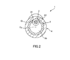
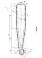
図1は、本発明のガイドワイヤの第1実施形態を示す部分縦断面側面図、図2は、図1中のA−A線断面図、図3は、図1に示すガイドワイヤの使用状態を順に示す図である。なお、以下では、説明の都合上、図1および図3中(図4、図8および図9についても同様)の右側を「基端」、左側を「先端」と言う。また、図1および図3中(図4、図8および図9についても同様)では、理解を容易にするため、ガイドワイヤの長さ方向を短縮し、ガイドワイヤの太さ方向を誇張して模式的に図示しており、長さ方向と太さ方向との比率は実際とは異なる。<First Embodiment>
1 is a partial longitudinal sectional side view showing a first embodiment of the guide wire of the present invention, FIG. 2 is a sectional view taken along line AA in FIG. 1, and FIG. 3 is a use state of the guide wire shown in FIG. FIG. In the following, for convenience of explanation, the right side in FIGS. 1 and 3 (the same applies to FIGS. 4, 8 and 9) is referred to as the “base end”, and the left side is referred to as the “tip”. Further, in FIGS. 1 and 3 (the same applies to FIGS. 4, 8 and 9), in order to facilitate understanding, the length direction of the guide wire is shortened and the thickness direction of the guide wire is exaggerated. It is schematically shown, and the ratio between the length direction and the thickness direction is different from the actual one.
図1に示すガイドワイヤ1は、本実施形態では、例えば比較的細い血管(管腔)100内に挿入して用いられるガイドワイヤである。このガイドワイヤ1は、長尺体で構成されたワイヤ本体2と、ワイヤ本体2の先端部(先端側の部分)に設置された造影マーカ(突出部)3と、ワイヤ本体2全体を造影マーカ3ごと覆う被覆層(樹脂被覆層)4とを備えている。
In the present embodiment, a guide wire 1 shown in FIG. 1 is a guide wire that is used by being inserted into a relatively thin blood vessel (lumen) 100, for example. The guide wire 1 includes a
ガイドワイヤ1の全長は、特に限定されないが、200〜5000mm程度であるのが好ましい。 The total length of the guide wire 1 is not particularly limited, but is preferably about 200 to 5000 mm.
ワイヤ本体2は、可撓性を有する、すなわち、柔軟性または弾性を有する1本の線材で構成されている。図1に示すように、ワイヤ本体2は、その先端部に設けられたテーパ部22と、テーパ部22の基端側に設けられた外径一定部23とで構成されている。
The
テーパ部22は、その外径φd3が先端方向に向かって漸減した外径漸減部である。なお、テーパ部22のテーパ角度(外径d3の減少率)は、図1に示す構成ではワイヤ長手方向(ワイヤ本体2の中心軸O1方向)に沿って一定であるが、これに限定されず、例えば、ワイヤ長手方向に沿って変化する部位があってもよい。この場合、例えば、テーパ角度が比較的大きい箇所と比較的小さい箇所とが複数回交互に繰り返して形成されているようなものでもよい。The tapered
そして、このテーパ部22が設けられていることにより、ワイヤ本体2は、全体として先細り形状をなすものとなる。これにより、ワイヤ本体2の剛性(曲げ剛性、ねじり剛性)を先端方向に向かって徐々に減少させることができ、その結果、ガイドワイヤ1は、先端部11に良好な狭窄部の通過性および柔軟性を得て、血管100等への追従性、安全性が向上するとともに、折れ曲がり等も防止することができる。また、ワイヤ本体2は、その先端側の部分では柔軟性に富み、基端側の部分では比較的剛性が高いものとなるので、先端部11の柔軟性と優れた操作性(押し込み性、トルク伝達性等)とを両立することができる。
And by providing this
外径一定部23は、その外径φd4がワイヤ本体2の中で最も大きく、ワイヤ長手方向に沿って一定となっている大径部である。なお、外径一定部23の外径φd4とテーパ部22の最大外径とは、ほぼ同等である。また、外径一定部23の基端部には、面取りを施した面取り部231が設けられている。The constant
ワイヤ本体2の構成材料としては、特に限定されず、例えば、ステンレス鋼(例えば、SUS304、SUS303、SUS316、SUS316L、SUS316J1、SUS316J1L、SUS405、SUS430、SUS434、SUS444、SUS429、SUS430F、SUS302等SUSの全品種)、ピアノ線、コバルト系合金、擬弾性を示す合金(超弾性合金を含む)などの各種金属材料を使用することができるが、そのなかでも特に、擬弾性を示す合金(超弾性合金を含む)が好ましく、より好ましくは超弾性合金である。
The constituent material of the
超弾性合金は、比較的柔軟であるとともに、復元性があり、曲がり癖が付き難いので、ワイヤ本体2を超弾性合金で構成することにより、ガイドワイヤ1は、特に、その先端側の部分に十分な柔軟性と曲げに対する復元性が得られ、複雑に湾曲・屈曲する血管等に対する追従性が向上し、より優れた操作性が得られるとともに、ワイヤ本体2が湾曲・屈曲変形を繰り返しても、ワイヤ本体2に備わる復元性により曲がり癖が付かないので、ガイドワイヤ1の使用中にワイヤ本体2に曲がり癖が付くことによる操作性の低下を防止することができる。
The superelastic alloy is relatively flexible, has a resilience, and is difficult to bend. Therefore, by configuring the
超弾性合金には、引張りによる応力−ひずみ曲線のいずれの形状も含み、As、Af、Ms、Mf等の変態点が顕著に測定できるものも、できないものも含み、応力により大きく変形(歪)し、応力の除去により元の形状にほぼ戻るものは全て含まれる。 Superelastic alloys include any shape of the stress-strain curve caused by tension, including those that can significantly measure transformation points such as As, Af, Ms, and Mf, and those that cannot be deformed. However, everything that returns to its original shape by removing stress is included.
超弾性合金の好ましい組成としては、49〜52原子%NiのNi−Ti合金等のNi−Ti系合金、38.5〜41.5重量%ZnのCu−Zn合金、1〜10重量%XのCu−Zn−X合金(Xは、Be、Si、Sn、Al、Gaのうちの少なくとも1種)、36〜38原子%AlのNi−Al合金等が挙げられる。このなかでも特に好ましいものは、上記のNi−Ti系合金である。なお、Ni−Ti系合金に代表される超弾性合金は、被覆層4の密着性にも優れている。
The preferred composition of the superelastic alloy is Ni-Ti alloy such as Ni-Ti alloy of 49-52 atomic% Ni, Cu-Zn alloy of 38.5-41.5 wt% Zn, 1-10 wt% X Cu-Zn-X alloy (X is at least one of Be, Si, Sn, Al, and Ga), 36-38 atomic% Al-Ni-Al alloy, and the like. Of these, the Ni-Ti alloy is particularly preferable. A superelastic alloy typified by a Ni—Ti alloy is also excellent in the adhesion of the
図1に示すように、ガイドワイヤ1の外表面には、その全体を被覆する被覆層4が設けられている。この被覆層4は、種々の目的で形成することができるが、その一例として、ガイドワイヤ1の摩擦(摺動抵抗)を低減し、摺動性を向上させることによってガイドワイヤ1の操作性を向上させることがある。
As shown in FIG. 1, the outer surface of the guide wire 1 is provided with a
ガイドワイヤ1の摩擦(摺動抵抗)の低減を図るためには、被覆層4は、以下に述べるような摩擦を低減し得る材料で構成されているのが好ましい。これにより、血管壁との摩擦抵抗(摺動抵抗)が低減されて摺動性が向上し、血管100内でのガイドワイヤ1の操作性がより良好なものとなる。また、ガイドワイヤ1の摺動抵抗が低くなることで、ガイドワイヤ1を血管100内で移動させたり、回転させたりした際に、ガイドワイヤ1のキンク(折れ曲がり)やねじれを確実に防止することができる。
In order to reduce the friction (sliding resistance) of the guide wire 1, the
このような摩擦を低減し得る材料としては、例えば、ポリエチレン、ポリプロピレン等のポリオレフィン、ポリ塩化ビニル、ポリエステル(PET、PBT等)、ポリアミド、ポリイミド、ポリウレタン、ポリスチレン、ポリカーボネート、シリコーン樹脂、フッ素系樹脂(PTFE、ETFE等)、またはこれらの複合材料が挙げられる。 Examples of materials that can reduce such friction include polyolefins such as polyethylene and polypropylene, polyvinyl chloride, polyesters (PET, PBT, etc.), polyamides, polyimides, polyurethanes, polystyrenes, polycarbonates, silicone resins, fluorine resins ( PTFE, ETFE, etc.) or a composite material thereof.
また、被覆層4は、ガイドワイヤ1を血管100等に挿入する際の安全性の向上を目的として設けることもできる。この目的のためには、被覆層4は柔軟性に富む材料(軟質材料、弾性材料)で構成されているのが好ましい。
The
このような柔軟性に富む材料としては、例えば、ポリエチレン、ポリプロピレン等のポリオレフィン、ポリ塩化ビニル、ポリエステル(PET、PBT等)、ポリアミド、ポリイミド、ポリウレタン、ポリスチレン、シリコーン樹脂、ポリウレタンエラストマー、ポリエステルエラストマー、ポリアミドエラストマー等の熱可塑性エラストマー、ラテックスゴム、シリコーンゴム等の各種ゴム材料、またはこれらのうちに2以上を組み合わせた複合材料が挙げられる。 Examples of such flexible materials include polyolefins such as polyethylene and polypropylene, polyvinyl chloride, polyester (PET, PBT, etc.), polyamide, polyimide, polyurethane, polystyrene, silicone resin, polyurethane elastomer, polyester elastomer, polyamide. Examples thereof include thermoplastic elastomers such as elastomers, various rubber materials such as latex rubber and silicone rubber, or composite materials in which two or more thereof are combined.
また、被覆層4は、先端41および基端42は、それぞれ、丸みを帯びている。これにより、ガイドワイヤ1を血管100等に押し込んで挿入した際に、先端41で血管を傷つけるのを確実に防止することができたり、基端42でガイドワイヤ1の操作者の指等を傷つけるのを確実に防止したりすることができる。
Moreover, the
また、被覆層4は、単層のものであってもよいし、2層以上の積層体でもよい。
The
ワイヤ本体2のテーパ部22には、当該ワイヤ本体2と別体の長尺な管状体(部材)で構成された造影マーカ3が設置されている。造影マーカ3は、その内側をテーパ部22が挿通しており、当該テーパ部22の途中、図1に示す構成ではできる限り先端側に配置され、固定部材5a、5bを介して固定されている。
On the
なお、固定部材5a、5bは、それぞれ、例えば接着剤、ろう材または半田であり、固定部材5aが造影マーカ3の先端部33を固定し、固定部材5bが造影マーカ3の基端部34を固定している。このように造影マーカ3がその両端部で固定されていることにより、当該造影マーカ3は、ワイヤ本体2に確実に固定され、よって、例えばガイドワイヤ1の使用中にワイヤ本体2から離脱するのが確実に防止される。
Each of the fixing
造影マーカ3は、例えば、金、白金、タングステン等の貴金属またはこれらを含む合金等のような金属材料で構成されている。このような金属材料は、X線不透過材料であり、造影マーカ3がX線造影性を有するものとなる。これにより、X線透視下でガイドワイヤ1の先端部11の位置を確認しつつ血管100内に挿入することができる。
The
この管状体で構成された造影マーカ3は、その外径φd5が中心軸O1方向に沿って一定であり、ワイヤ本体2の外径一定部23の外径φd4よりも大きい。The
また、造影マーカ3には、その管壁を厚さ方向に貫通し(欠損し)、中心軸O1方向に沿ったスリット(欠損部)31が形成されている。換言すれば、図2に示すように、造影マーカ3は、その横断面形状が「C」字状をなす部材で構成されている。そして、スリット31(溝)内にテーパ部22の一部が位置している。このような配置により、造影マーカ3は、ワイヤ本体2の中心軸O1に対して偏心した位置(図1中の下側)に、その偏心方向(図1中の下方)に向かって突出することとなる、すなわち、造影マーカ3の中心軸O2がワイヤ本体2の中心軸O1とズレて配置されている。Further, the
以上のような構成の造影マーカ3を備えるガイドワイヤ1を血管100に挿入して用いた場合について、図3を参照しつつ説明する。なお、血管100には、その長手方向の途中から分岐した側枝101がある。そして、ここでは、ガイドワイヤ1を側枝101に挿入させる場合について説明する。また、この手技は、X線造影下で行なわれる。
A case where the guide wire 1 including the
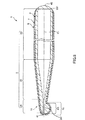
図3(a)に示す状態は、ガイドワイヤ1が血管100の奥側(末梢側)に向かって押し込まれている。また、この状態では、ガイドワイヤ1は、その最大外径φd1よりも若干大きい内径φd2の比較的細い血管100内に挿入されているため、当該挿入された部分、特に先端部11が血管の形状にならって、直線状に近い状態(直線状態)に矯正されている。In the state shown in FIG. 3A, the guide wire 1 is pushed toward the back side (peripheral side) of the
図3(a)に示す状態から、ガイドワイヤ1をさらに押し込む。この際、造影マーカ3を確認しつつ、すなわち、手掛かりとして、造影マーカ3で突出した部分(以下この部分を「先端突出部12」と言う)を図中下側に向けておく。
The guide wire 1 is further pushed in from the state shown in FIG. At this time, while confirming the
そして、ガイドワイヤ1の先端突出部12が側枝101の根元部(分岐部)102に到達したとき、図3(b)示すように、当該先端突出部12が根元部102を確実に捕える、すなわち、根元部102に係合する。
And when the front-end |
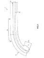
図3(b)に示す状態のままガイドワイヤ1を押し込むと、図3(c)に示すように、先端部11が湾曲しつつ、側枝101に確実に向かうこととなり、その結果、ガイドワイヤ1を側枝101に確実に挿入させることができる。
When the guide wire 1 is pushed in while being in the state shown in FIG. 3B, the
このように、ガイドワイヤ1では、側枝101を有する血管100内に挿入して用いた際に、当該血管100に対し進ませたい方向、すなわち、図3に示す状態では側枝101の方向に確実に進ませることができ、よって、操作性に優れたものとなっている。
As described above, when the guide wire 1 is used by being inserted into the
<第2実施形態>
図4は、本発明のガイドワイヤの第2実施形態を示す部分縦断面側面図、図5は、図4中のB−B線断面図である。Second Embodiment
FIG. 4 is a partial longitudinal sectional side view showing a second embodiment of the guide wire of the present invention, and FIG. 5 is a sectional view taken along the line BB in FIG.
以下、これらの図を参照して本発明のガイドワイヤの第2実施形態について説明するが、前述した実施形態との相違点を中心に説明し、同様の事項はその説明を省略する。 Hereinafter, the second embodiment of the guide wire of the present invention will be described with reference to these drawings, but the description will focus on the differences from the above-described embodiment, and the description of the same matters will be omitted.
本実施形態は、主に、造影マーカの形状およびワイヤ本体に対する固定方法が異なること以外は前記第1実施形態と同様である。 This embodiment is mainly the same as the first embodiment except that the shape of the contrast marker and the fixing method to the wire body are different.
図4に示すように、本実施形態では、ワイヤ本体2は、テーパ部22よりも先端側に、板状部(平板部)24を有している。この板状部24は、板状(リボン状)をなしている。
As shown in FIG. 4, in the present embodiment, the
造影マーカ3Aは、ワイヤ本体2と別体で構成され、板状部24の一方の面側(図4、図5中では下側の面241)に配置されている。この造影マーカ3Aの形状は、半球状をなしている。このような配置と形状により、造影マーカ3Aは、ワイヤ本体2の中心軸O1に対して偏心した位置(図4中の下側)に、その偏心方向(図4中の下方)に向かって突出することとなる。これにより、ガイドワイヤ1の先端部11には、造影マーカ3Aで突出した先端突出部12が形成される。そして、前記第1実施形態と同様に、ガイドワイヤ1を血管100内に挿入した際に、先端突出部12で側枝101の根元部102を確実に捕えることができ、ガイドワイヤ1を側枝101に確実に向かわせることとができる。The
また、造影マーカ3Aのワイヤ本体2に対する固定方法(固定構造)は、本実施形態では、次のようになっている。
Moreover, the fixing method (fixing structure) with respect to the wire
図5に示すように、板状部24には、その厚さ方向に貫通する円形の貫通孔242が形成されている。そして、貫通孔242に対し、造影マーカ3Aの図5中の上面から柱状に突出形成された柱状部36を挿入し、当該柱状部36の上部を潰して塑性変形させる。これにより、柱状部36に変形部361が形成され、よって、造影マーカ3Aがワイヤ本体2から離脱するのが確実に防止される。
As shown in FIG. 5, the plate-
また、ガイドワイヤ1の少なくとも先端部11では、被覆層4上に、さらに、親水性材料をコーティングしてなる親水性層6が、例えばポリ塩化ビニル(PVC(polyvinyl chloride))で構成された下地層7を介して形成されている。これにより、親水性層6を構成する親水性材料が湿潤して潤滑性を生じ、ガイドワイヤ1の摩擦(摺動抵抗)が低減し、摺動性が向上する。従って、ガイドワイヤ1の操作性が向上する。
Further, at least at the
親水性材料としては、例えば、セルロース系高分子物質、ポリエチレンオキサイド系高分子物質、無水マレイン酸系高分子物質(例えば、メチルビニルエーテル−無水マレイン酸共重合体のような無水マレイン酸共重合体)、アクリルアミド系高分子物質(例えば、ポリアクリルアミド、ポリグリシジルメタクリレート−ジメチルアクリルアミド(PGMA−DMAA)のブロック共重合体)、水溶性ナイロン、ポリビニルアルコール、ポリビニルピロリドン等が挙げられる。 Examples of hydrophilic materials include cellulose-based polymer materials, polyethylene oxide-based polymer materials, and maleic anhydride-based polymer materials (for example, maleic anhydride copolymers such as methyl vinyl ether-maleic anhydride copolymer). Acrylamide polymer substances (for example, polyacrylamide, polyglycidyl methacrylate-dimethylacrylamide (PGMA-DMAA) block copolymer), water-soluble nylon, polyvinyl alcohol, polyvinylpyrrolidone and the like.
<第3実施形態>
図6は、本発明のガイドワイヤ(第3実施形態)の先端部を示す横断面図である。<Third Embodiment>
FIG. 6 is a cross-sectional view showing the distal end portion of the guide wire (third embodiment) of the present invention.
以下、この図を参照して本発明のガイドワイヤの第3実施形態について説明するが、前述した実施形態との相違点を中心に説明し、同様の事項はその説明を省略する。 Hereinafter, the third embodiment of the guide wire of the present invention will be described with reference to this figure, but the description will focus on the differences from the above-described embodiment, and the description of the same matters will be omitted.
本実施形態は、造影マーカのワイヤ本体に対する固定方法が異なること以外は前記第2実施形態と同様である。 This embodiment is the same as the second embodiment except that the method of fixing the contrast marker to the wire body is different.
造影マーカ3Aのワイヤ本体2に対する固定方法(固定構造)は、本実施形態では、次のようになっている。
The fixing method (fixing structure) of the
図6に示すように、造影マーカ3Aの板状部24の下側の面241と接する面には、貫通孔242の内径それよりも若干大きい外径の嵌合部35が突出形成されている。この嵌合部35を貫通孔242に圧入して、嵌合部35が貫通孔242に嵌合することにより、造影マーカ3Aをワイヤ本体2に対し確実に固定することができる。
As shown in FIG. 6, a
<第4実施形態>
図7は、本発明のガイドワイヤ(第4実施形態)の先端部を示す横断面図である。<Fourth embodiment>
FIG. 7 is a cross-sectional view showing the distal end portion of the guide wire (fourth embodiment) of the present invention.
以下、この図を参照して本発明のガイドワイヤの第4実施形態について説明するが、前述した実施形態との相違点を中心に説明し、同様の事項はその説明を省略する。 Hereinafter, the guide wire according to the fourth embodiment of the present invention will be described with reference to the drawings. However, the difference from the above-described embodiment will be mainly described, and the description of the same matters will be omitted.
本実施形態は、造影マーカのワイヤ本体に対する固定方法が異なること以外は前記第2実施形態と同様である。 This embodiment is the same as the second embodiment except that the method of fixing the contrast marker to the wire body is different.
造影マーカ3Aのワイヤ本体2に対する固定方法(固定構造)は、本実施形態では、次のようになっている。
The fixing method (fixing structure) of the
図7に示す構成では、造影マーカ3Aは、板状部24の下側の面241に、圧着による方法、溶接による方法、接着による方法、めっきを施す方法のうちの少なくとも1つの方法を用いて、ワイヤ本体2に対し確実に固定されている。
In the configuration shown in FIG. 7, the
<第5実施形態>
図8は、本発明のガイドワイヤの第5実施形態を示す部分縦断面側面図である。<Fifth Embodiment>
FIG. 8 is a partial vertical cross-sectional side view showing a fifth embodiment of the guide wire of the present invention.
以下、この図を参照して本発明のガイドワイヤの第5実施形態について説明するが、前述した実施形態との相違点を中心に説明し、同様の事項はその説明を省略する。 Hereinafter, the fifth embodiment of the guide wire of the present invention will be described with reference to this drawing. However, the description will focus on the differences from the above-described embodiment, and the description of the same matters will be omitted.
本実施形態は、造影マーカの構成材料が異なること以外は前記第2実施形態と同様である。 The present embodiment is the same as the second embodiment except that the constituent material of the contrast marker is different.
図8に示す本実施形態では、造影マーカ3Bは、金属粉末を含有する樹脂材料で構成れている。この金属粉末は、樹脂材料全体にわたって均一に分散しており、例えば、金、白金、タングステン等の貴金属またはこれらを含む合金等のような金属材料で構成されている。このような金属材料は、X線不透過材料であり、造影マーカ3BがX線造影性を有するものとなる。 In the present embodiment shown in FIG. 8, the contrast marker 3B is made of a resin material containing metal powder. The metal powder is uniformly dispersed throughout the resin material, and is made of a metal material such as a noble metal such as gold, platinum, tungsten, or an alloy containing these metals. Such a metal material is a radiopaque material, and the contrast marker 3B has X-ray contrast properties.
また、造影マーカ3Bを構成する樹脂材料としては、被覆層4の構成材料と同様のものが用いられている。これにより、造影マーカ3Bと被覆層4とを一体的に形成することができ、よって、ガイドワイヤ1の製造が容易となる。
Further, as the resin material constituting the contrast marker 3B, the same material as that of the
<第6実施形態>
図9は、本発明のガイドワイヤの第6実施形態を示す側面図である。<Sixth Embodiment>
FIG. 9 is a side view showing a sixth embodiment of the guide wire of the present invention.
以下、この図を参照して本発明のガイドワイヤの第6実施形態について説明するが、前述した実施形態との相違点を中心に説明し、同様の事項はその説明を省略する。
本実施形態は、ワイヤ本体の形状が異なること以外は前記第1実施形態と同様である。Hereinafter, the sixth embodiment of the guide wire according to the present invention will be described with reference to this figure. However, the difference from the above-described embodiment will be mainly described, and the description of the same matters will be omitted.
This embodiment is the same as the first embodiment except that the shape of the wire body is different.
図9に示すように、本実施形態では、ワイヤ本体2は、その先端部、すなわち、テーパ部22が、外力を付与しない自然状態で、円弧状に(一方向に)湾曲した湾曲部を構成している。
As shown in FIG. 9, in the present embodiment, the
また、造影マーカ3は、円弧状に湾曲したテーパ部22に対し、その湾曲内側を向いている。これにより、ガイドワイヤ1を血管100内に挿入した際、先端突出部12で側枝101の根元部102をより確実に捕えることができる。
Further, the
<第7実施形態>
図10は、本発明のガイドワイヤ(第7実施形態)の先端部を示す横断面図である。<Seventh embodiment>
FIG. 10 is a cross-sectional view showing the distal end portion of the guide wire (seventh embodiment) of the present invention.
以下、この図を参照して本発明のガイドワイヤの第7実施形態について説明するが、前述した実施形態との相違点を中心に説明し、同様の事項はその説明を省略する。
本実施形態は、造影マーカの形状が異なること以外は前記第1実施形態と同様である。Hereinafter, the seventh embodiment of the guide wire of the present invention will be described with reference to this drawing. However, the description will focus on the differences from the above-described embodiment, and the description of the same matters will be omitted.
This embodiment is the same as the first embodiment except that the shape of the contrast marker is different.
図10に示す本実施形態では、造影マーカ3Cは、円柱状をなし、その外周部に、中心軸O2方向に延在する溝(欠損部)37が形成されている。そして、この溝37をワイヤ本体2のテーパ部22が挿通している。このような位置関係により、造影マーカ3Cは、ワイヤ本体2の中心軸O1に対して偏心した位置(図10中の下側)に、その偏心方向(図10中の下方)に向かって突出することとなる、すなわち、造影マーカ3Cの中心軸O2がワイヤ本体2の中心軸O1とズレて配置される。In the present embodiment shown in FIG. 10, the
このような構成の造影マーカ3Cを有するガイドワイヤ1でも、前記第1実施形態と同様に、ガイドワイヤ1の先端突出部12が側枝101の根元部102を確実に捕えることができる。これにより、ガイドワイヤ1の先端部11を側枝101に確実に向かわせて、ガイドワイヤ1を側枝101に確実に挿入させることができる。
Even in the guide wire 1 having the
<第8実施形態>
図11は、本発明のガイドワイヤ(第8実施形態)の先端部を示す横断面図である。<Eighth Embodiment>
FIG. 11 is a cross-sectional view showing the distal end portion of the guide wire (eighth embodiment) of the present invention.
以下、この図を参照して本発明のガイドワイヤの第8実施形態について説明するが、前述した実施形態との相違点を中心に説明し、同様の事項はその説明を省略する。
本実施形態は、造影マーカの形状が異なること以外は前記第1実施形態と同様である。Hereinafter, the eighth embodiment of the guide wire according to the present invention will be described with reference to this drawing. However, the difference from the above-described embodiment will be mainly described, and the description of the same matters will be omitted.
This embodiment is the same as the first embodiment except that the shape of the contrast marker is different.
図11に示す本実施形態では、造影マーカ3Dは、円柱状をなし、中心軸O2と偏心した位置に、当該中心軸O2方向に貫通して延在する貫通孔(欠損部)38が形成されている。そして、この貫通孔38をワイヤ本体2のテーパ部22が挿通している。これにより、造影マーカ3Cの中心軸O2がワイヤ本体2の中心軸O1とズレて配置される。In the present embodiment shown in FIG. 11, the
このような構成の造影マーカ3Dを有するガイドワイヤ1でも、前記第1実施形態と同様に、ガイドワイヤ1の先端突出部12が側枝101の根元部102を確実に捕えることができる。これにより、ガイドワイヤ1の先端部11を側枝101に確実に向かわせて、ガイドワイヤ1を側枝101に確実に挿入させることができる。
Even in the guidewire 1 having the
以上、本発明のガイドワイヤを図示の実施形態について説明したが、本発明は、これに限定されるものではなく、ガイドワイヤを構成する各部は、同様の機能を発揮し得る任意の構成のものと置換することができる。また、任意の構成物が付加されていてもよい。 As mentioned above, although the guide wire of this invention was demonstrated about embodiment of illustration, this invention is not limited to this, Each part which comprises a guide wire is a thing of arbitrary structures which can exhibit the same function. Can be substituted. Moreover, arbitrary components may be added.
また、本発明のガイドワイヤは、前記各実施形態のうちの、任意の2以上の構成(特徴)を組み合わせたものであってもよい。 In addition, the guide wire of the present invention may be a combination of any two or more configurations (features) of the above embodiments.
また、ワイヤ本体は、前記各実施形態では1本の線材で構成されているが、先端側に配置された第1ワイヤと、第1ワイヤの基端側に配置された第2ワイヤとの2本の線材で構成され、これら線材同士が溶接により接合(連結)してなるものであってもよい。この場合、第1ワイヤは、超弾性合金で構成されているのが好ましく、第2ワイヤは、ステンレス鋼で構成されているのが好ましい。 Moreover, although the wire main body is comprised by one wire in each said embodiment, 2 of the 1st wire arrange | positioned at the front end side and the 2nd wire arrange | positioned at the base end side of the 1st wire. It may be composed of a wire rod, and these wire rods may be joined (connected) by welding. In this case, the first wire is preferably made of a superelastic alloy, and the second wire is preferably made of stainless steel.
また、ワイヤ本体の先端部に設けられ、該ワイヤ本体の中心軸に対して偏心した位置に、その偏心方向に向かって突出した突出部は、前記各実施形態では造影性を有するものであったが、これに限定されず、例えば、造影性が省略されたものであってもよい。この場合、突出部の突出方向(偏心方向)を確認するためのマーカを、突出部とは別に設けるのが好ましい。このマーカとしては、特に限定されず、例えば、欠損部を有する部材、すなわち、横断面形状が「C」字状をなす部材を用いることができる。 Further, the protruding portion provided at the tip of the wire main body and protruding toward the eccentric direction at a position eccentric with respect to the central axis of the wire main body has contrast properties in each of the embodiments. However, the present invention is not limited to this, and for example, the contrast may be omitted. In this case, it is preferable that a marker for confirming the protruding direction (eccentric direction) of the protruding portion is provided separately from the protruding portion. The marker is not particularly limited, and for example, a member having a defect portion, that is, a member having a “C” shape in cross section can be used.
本発明のガイドワイヤは、撓性を有する長尺体で構成されたワイヤ本体と、前記ワイヤ本体の先端部に設けられ、該ワイヤ本体の中心軸に対して偏心した位置に、その偏心方向に向かって突出した突出部とを備える。
そのため、例えば分岐部を有する管腔内にガイドワイヤを挿入して押し込んだ際に、当該ガイドワイヤをその管腔に対し進ませたい方向に確実に進ませることができる。例えばガイドワイヤを分岐部側に進ませたい場合、ガイドワイヤの突出部で突出した部分を、分岐部に係合させることができる。そして、この状態のままガイドワイヤを先端方向に向かって押し込むと、当該ガイドワイヤは、分岐部側に確実に向かう、すなわち、進むこととなる。このように、本発明によれば、挿入された管腔に対し、進ませたい方向に確実に進ませることができ、よって、操作性に優れたものとなっている。
従って、本発明のガイドワイヤは、産業上の利用可能性を有する。A guide wire according to the present invention is provided at a distal end portion of a wire body composed of a flexible long body and the wire body, and in a position eccentric with respect to the central axis of the wire body. A projecting portion projecting toward the head.
Therefore, for example, when a guide wire is inserted and pushed into a lumen having a branching portion, the guide wire can be surely advanced in a direction in which the guide wire is to be advanced relative to the lumen. For example, when it is desired to advance the guide wire toward the branching portion, the portion protruding at the protruding portion of the guidewire can be engaged with the branching portion. When the guide wire is pushed toward the distal end in this state, the guide wire is surely directed toward the branching portion, that is, advances. As described above, according to the present invention, the inserted lumen can be surely advanced in the direction in which it is desired to be advanced, and thus the operability is excellent.
Therefore, the guide wire of the present invention has industrial applicability.
1 ガイドワイヤ
11 先端部
12 先端突出部
2 ワイヤ本体
22 テーパ部
23 外径一定部
231 面取り部
24 板状部(平板部)
241 下側の面
242 貫通孔
3、3A、3B、3C、3D 造影マーカ(突出部)
31 スリット(欠損部)
33 先端部
34 基端部
35 嵌合部
36 柱状部
361 変形部
37 溝(欠損部)
38 貫通孔(欠損部)
4 被覆層(樹脂被覆層)
41 先端
42 基端
5a、5b 固定部材
6 親水性層
7 下地層
100 血管(管腔)
101 側枝
102 根元部(分岐部)
φd1 最大外径
φd3、φd4、φd5 外径
φd2 内径
O1、O2 中心軸DESCRIPTION OF SYMBOLS 1
241
31 Slit (Deficient part)
33
38 Through hole (defect)
4 Coating layer (resin coating layer)
41
101
φd 1 maximum outer diameter φd 3 , φd 4 , φd 5 outer diameter φd 2 inner diameter O 1 , O 2 central axis
Claims (8)
前記ワイヤ本体の先端部に設けられ、該ワイヤ本体の中心軸に対して偏心した位置に、その偏心方向に向かって突出した突出部と、
前記ワイヤ本体を前記突出部ごと覆って外層となる被覆層とを備え、
前記被覆層には、前記突出部の突出形状にならって突出した先端突出部が形成されていることを特徴とするガイドワイヤ。 A wire body composed of an elongated body having flexibility;
A protrusion provided at the tip of the wire main body and protruding toward the eccentric direction at a position eccentric with respect to the central axis of the wire main body ;
A covering layer that covers the wire body together with the protruding portion and serves as an outer layer ;
The guide wire according to claim 1, wherein a tip protruding portion that protrudes in accordance with the protruding shape of the protruding portion is formed on the covering layer .
前記先端突出部は、前記血管の分岐部に係合して、当該ガイドワイヤを前記分岐部の分岐方向に導く部分である請求項1に記載のガイドワイヤ。2. The guide wire according to claim 1, wherein the tip protruding portion is a portion that engages with a branch portion of the blood vessel and guides the guide wire in a branch direction of the branch portion.
前記突出部は、前記ワイヤ本体と別体で構成され、前記テーパ部が挿通する部材である請求項1または2に記載のガイドワイヤ。 The wire body has a tapered portion whose outer diameter gradually decreases in the distal direction at the distal end thereof,
3. The guide wire according to claim 1 , wherein the protruding portion is configured separately from the wire main body and is a member through which the tapered portion is inserted.
前記突出部は、前記部材の長手方向に延在する溝を有し、
前記溝内に前記テーパ部の一部が位置している請求項3に記載のガイドワイヤ。 The member has a long shape,
The protrusion has a groove extending in a longitudinal direction of the member,
The guide wire according to claim 3 , wherein a part of the tapered portion is located in the groove.
前記部材は、管状体であり、該管状体の外径は、前記外径一定部の外径よりも大きい請求項3または4に記載のガイドワイヤ。The guide wire according to claim 3 or 4, wherein the member is a tubular body, and an outer diameter of the tubular body is larger than an outer diameter of the constant outer diameter portion.
前記突出部は、前記ワイヤ本体と別体で構成され、前記板状部の一方の面側に配置されたものである請求項1または2に記載のガイドワイヤ。 The wire body has a plate-like portion that forms a plate shape at the tip thereof,
3. The guide wire according to claim 1 , wherein the protruding portion is configured separately from the wire main body and is disposed on one surface side of the plate-like portion.
前記突出部は、前記湾曲部に対しその湾曲内側を向いている請求項1ないし6のいずれか1項に記載のガイドワイヤ。 The wire body has a curved portion that is curved in one direction in a natural state in which no external force is applied to the distal end portion thereof,
The guide wire according to any one of claims 1 to 6 , wherein the protruding portion is directed inward of the bending portion with respect to the bending portion.
Applications Claiming Priority (3)
| Application Number | Priority Date | Filing Date | Title |
|---|---|---|---|
| JP2012014661 | 2012-01-26 | ||
| JP2012014661 | 2012-01-26 | ||
| PCT/JP2012/077410 WO2013111404A1 (en) | 2012-01-26 | 2012-10-24 | Guide wire |
Publications (2)
| Publication Number | Publication Date |
|---|---|
| JPWO2013111404A1 JPWO2013111404A1 (en) | 2015-05-11 |
| JP6155199B2 true JP6155199B2 (en) | 2017-06-28 |
Family
ID=48873146
Family Applications (1)
| Application Number | Title | Priority Date | Filing Date |
|---|---|---|---|
| JP2013555121A Active JP6155199B2 (en) | 2012-01-26 | 2012-10-24 | Guide wire |
Country Status (2)
| Country | Link |
|---|---|
| JP (1) | JP6155199B2 (en) |
| WO (1) | WO2013111404A1 (en) |
Families Citing this family (2)
| Publication number | Priority date | Publication date | Assignee | Title |
|---|---|---|---|---|
| CN108175925A (en) * | 2018-02-11 | 2018-06-19 | 李梦强 | The eccentric prostate dilator of visualization |
| CN113995952B (en) * | 2021-10-25 | 2022-11-04 | 苏州心擎医疗技术有限公司 | Catheter device |
Family Cites Families (7)
| Publication number | Priority date | Publication date | Assignee | Title |
|---|---|---|---|---|
| JP4473266B2 (en) * | 2004-03-15 | 2010-06-02 | テルモ株式会社 | Guide wire assembly |
| JP5430065B2 (en) * | 2007-12-28 | 2014-02-26 | テルモ株式会社 | Guide wire |
| ATE550065T1 (en) * | 2007-12-28 | 2012-04-15 | Terumo Corp | GUIDE WIRE |
| WO2009119387A1 (en) * | 2008-03-28 | 2009-10-01 | テルモ株式会社 | Guide wire and method of manufacturing guide wire |
| JP2010207251A (en) * | 2009-03-06 | 2010-09-24 | Olympus Corp | Guide wire |
| JP2010259624A (en) * | 2009-05-07 | 2010-11-18 | Hi-Lex Corporation | Guide wire and manufacturing method thereof |
| JP5451779B2 (en) * | 2009-12-28 | 2014-03-26 | テルモ株式会社 | Guide wire |
-
2012
- 2012-10-24 WO PCT/JP2012/077410 patent/WO2013111404A1/en active Application Filing
- 2012-10-24 JP JP2013555121A patent/JP6155199B2/en active Active
Also Published As
| Publication number | Publication date |
|---|---|
| JPWO2013111404A1 (en) | 2015-05-11 |
| WO2013111404A1 (en) | 2013-08-01 |
Similar Documents
| Publication | Publication Date | Title |
|---|---|---|
| JP5020630B2 (en) | Guide wire | |
| JP6082807B2 (en) | Guide wire | |
| JP4981471B2 (en) | Guide wire | |
| JP6109749B2 (en) | Guide wire | |
| US20140336594A1 (en) | Guide wire | |
| JP2008161589A (en) | Guide wire | |
| JP6759069B2 (en) | Guide wire | |
| JP6155199B2 (en) | Guide wire | |
| JP5473677B2 (en) | Guide wire | |
| JP2011206174A (en) | Guide wire | |
| US20170072170A1 (en) | Guide wire and method for manufacturing a guide wire | |
| JP5931479B2 (en) | Guide wire | |
| JP4405252B2 (en) | Medical wire | |
| JP5953055B2 (en) | Guide wire | |
| US9808604B2 (en) | Guide wire | |
| JP5073713B2 (en) | Guide wire | |
| JP4447597B2 (en) | Guide wire | |
| JP2013154070A (en) | Guide wire | |
| JP5019868B2 (en) | Guide wire | |
| WO2014162389A1 (en) | Guide wire | |
| JP6347632B2 (en) | Guide wire | |
| JP2013135812A (en) | Guide wire | |
| JP2004065794A (en) | Guide wire | |
| JP5979879B2 (en) | Guide wire | |
| JP2008110266A (en) | Guide wire |
Legal Events
| Date | Code | Title | Description |
|---|---|---|---|
| A621 | Written request for application examination |
Free format text: JAPANESE INTERMEDIATE CODE: A621 Effective date: 20151006 |
|
| A131 | Notification of reasons for refusal |
Free format text: JAPANESE INTERMEDIATE CODE: A131 Effective date: 20161004 |
|
| A521 | Request for written amendment filed |
Free format text: JAPANESE INTERMEDIATE CODE: A523 Effective date: 20161125 |
|
| TRDD | Decision of grant or rejection written | ||
| A01 | Written decision to grant a patent or to grant a registration (utility model) |
Free format text: JAPANESE INTERMEDIATE CODE: A01 Effective date: 20170523 |
|
| A61 | First payment of annual fees (during grant procedure) |
Free format text: JAPANESE INTERMEDIATE CODE: A61 Effective date: 20170605 |
|
| R150 | Certificate of patent or registration of utility model |
Ref document number: 6155199 Country of ref document: JP Free format text: JAPANESE INTERMEDIATE CODE: R150 |
|
| R250 | Receipt of annual fees |
Free format text: JAPANESE INTERMEDIATE CODE: R250 |
|
| R250 | Receipt of annual fees |
Free format text: JAPANESE INTERMEDIATE CODE: R250 |
|
| R250 | Receipt of annual fees |
Free format text: JAPANESE INTERMEDIATE CODE: R250 |
|
| R250 | Receipt of annual fees |
Free format text: JAPANESE INTERMEDIATE CODE: R250 |