EP3199185B1 - Hohle tubusförmige medikamentenbeschichtete vorrichtungen - Google Patents
Hohle tubusförmige medikamentenbeschichtete vorrichtungen Download PDFInfo
- Publication number
- EP3199185B1 EP3199185B1 EP17157525.1A EP17157525A EP3199185B1 EP 3199185 B1 EP3199185 B1 EP 3199185B1 EP 17157525 A EP17157525 A EP 17157525A EP 3199185 B1 EP3199185 B1 EP 3199185B1
- Authority
- EP
- European Patent Office
- Prior art keywords
- tube
- etchant
- remaining
- core
- stent
- Prior art date
- Legal status (The legal status is an assumption and is not a legal conclusion. Google has not performed a legal analysis and makes no representation as to the accuracy of the status listed.)
- Active
Links
Images






Classifications
-
- A—HUMAN NECESSITIES
- A61—MEDICAL OR VETERINARY SCIENCE; HYGIENE
- A61F—FILTERS IMPLANTABLE INTO BLOOD VESSELS; PROSTHESES; DEVICES PROVIDING PATENCY TO, OR PREVENTING COLLAPSING OF, TUBULAR STRUCTURES OF THE BODY, e.g. STENTS; ORTHOPAEDIC, NURSING OR CONTRACEPTIVE DEVICES; FOMENTATION; TREATMENT OR PROTECTION OF EYES OR EARS; BANDAGES, DRESSINGS OR ABSORBENT PADS; FIRST-AID KITS
- A61F2/00—Filters implantable into blood vessels; Prostheses, i.e. artificial substitutes or replacements for parts of the body; Appliances for connecting them with the body; Devices providing patency to, or preventing collapsing of, tubular structures of the body, e.g. stents
- A61F2/82—Devices providing patency to, or preventing collapsing of, tubular structures of the body, e.g. stents
- A61F2/86—Stents in a form characterised by the wire-like elements; Stents in the form characterised by a net-like or mesh-like structure
- A61F2/90—Stents in a form characterised by the wire-like elements; Stents in the form characterised by a net-like or mesh-like structure characterised by a net-like or mesh-like structure
- A61F2/91—Stents in a form characterised by the wire-like elements; Stents in the form characterised by a net-like or mesh-like structure characterised by a net-like or mesh-like structure made from perforated sheets or tubes, e.g. perforated by laser cuts or etched holes
-
- A—HUMAN NECESSITIES
- A61—MEDICAL OR VETERINARY SCIENCE; HYGIENE
- A61L—METHODS OR APPARATUS FOR STERILISING MATERIALS OR OBJECTS IN GENERAL; DISINFECTION, STERILISATION OR DEODORISATION OF AIR; CHEMICAL ASPECTS OF BANDAGES, DRESSINGS, ABSORBENT PADS OR SURGICAL ARTICLES; MATERIALS FOR BANDAGES, DRESSINGS, ABSORBENT PADS OR SURGICAL ARTICLES
- A61L31/00—Materials for other surgical articles, e.g. stents, stent-grafts, shunts, surgical drapes, guide wires, materials for adhesion prevention, occluding devices, surgical gloves, tissue fixation devices
- A61L31/14—Materials characterised by their function or physical properties, e.g. injectable or lubricating compositions, shape-memory materials, surface modified materials
- A61L31/16—Biologically active materials, e.g. therapeutic substances
-
- A—HUMAN NECESSITIES
- A61—MEDICAL OR VETERINARY SCIENCE; HYGIENE
- A61M—DEVICES FOR INTRODUCING MEDIA INTO, OR ONTO, THE BODY; DEVICES FOR TRANSDUCING BODY MEDIA OR FOR TAKING MEDIA FROM THE BODY; DEVICES FOR PRODUCING OR ENDING SLEEP OR STUPOR
- A61M25/00—Catheters; Hollow probes
- A61M25/0009—Making of catheters or other medical or surgical tubes
- A61M25/0015—Making lateral openings in a catheter tube, e.g. holes, slits, ports, piercings of guidewire ports; Methods for processing the holes, e.g. smoothing the edges
-
- A—HUMAN NECESSITIES
- A61—MEDICAL OR VETERINARY SCIENCE; HYGIENE
- A61B—DIAGNOSIS; SURGERY; IDENTIFICATION
- A61B17/00—Surgical instruments, devices or methods
- A61B17/56—Surgical instruments or methods for treatment of bones or joints; Devices specially adapted therefor
- A61B17/58—Surgical instruments or methods for treatment of bones or joints; Devices specially adapted therefor for osteosynthesis, e.g. bone plates, screws or setting implements
- A61B17/68—Internal fixation devices, including fasteners and spinal fixators, even if a part thereof projects from the skin
- A61B17/84—Fasteners therefor or fasteners being internal fixation devices
- A61B17/86—Pins or screws or threaded wires; nuts therefor
- A61B17/8605—Heads, i.e. proximal ends projecting from bone
- A61B17/861—Heads, i.e. proximal ends projecting from bone specially shaped for gripping driver
-
- A—HUMAN NECESSITIES
- A61—MEDICAL OR VETERINARY SCIENCE; HYGIENE
- A61B—DIAGNOSIS; SURGERY; IDENTIFICATION
- A61B17/00—Surgical instruments, devices or methods
- A61B17/56—Surgical instruments or methods for treatment of bones or joints; Devices specially adapted therefor
- A61B17/58—Surgical instruments or methods for treatment of bones or joints; Devices specially adapted therefor for osteosynthesis, e.g. bone plates, screws or setting implements
- A61B17/68—Internal fixation devices, including fasteners and spinal fixators, even if a part thereof projects from the skin
- A61B17/84—Fasteners therefor or fasteners being internal fixation devices
- A61B17/86—Pins or screws or threaded wires; nuts therefor
- A61B17/864—Pins or screws or threaded wires; nuts therefor hollow, e.g. with socket or cannulated
-
- A—HUMAN NECESSITIES
- A61—MEDICAL OR VETERINARY SCIENCE; HYGIENE
- A61F—FILTERS IMPLANTABLE INTO BLOOD VESSELS; PROSTHESES; DEVICES PROVIDING PATENCY TO, OR PREVENTING COLLAPSING OF, TUBULAR STRUCTURES OF THE BODY, e.g. STENTS; ORTHOPAEDIC, NURSING OR CONTRACEPTIVE DEVICES; FOMENTATION; TREATMENT OR PROTECTION OF EYES OR EARS; BANDAGES, DRESSINGS OR ABSORBENT PADS; FIRST-AID KITS
- A61F2/00—Filters implantable into blood vessels; Prostheses, i.e. artificial substitutes or replacements for parts of the body; Appliances for connecting them with the body; Devices providing patency to, or preventing collapsing of, tubular structures of the body, e.g. stents
- A61F2/82—Devices providing patency to, or preventing collapsing of, tubular structures of the body, e.g. stents
- A61F2/86—Stents in a form characterised by the wire-like elements; Stents in the form characterised by a net-like or mesh-like structure
- A61F2/90—Stents in a form characterised by the wire-like elements; Stents in the form characterised by a net-like or mesh-like structure characterised by a net-like or mesh-like structure
- A61F2/91—Stents in a form characterised by the wire-like elements; Stents in the form characterised by a net-like or mesh-like structure characterised by a net-like or mesh-like structure made from perforated sheets or tubes, e.g. perforated by laser cuts or etched holes
- A61F2/915—Stents in a form characterised by the wire-like elements; Stents in the form characterised by a net-like or mesh-like structure characterised by a net-like or mesh-like structure made from perforated sheets or tubes, e.g. perforated by laser cuts or etched holes with bands having a meander structure, adjacent bands being connected to each other
-
- A—HUMAN NECESSITIES
- A61—MEDICAL OR VETERINARY SCIENCE; HYGIENE
- A61L—METHODS OR APPARATUS FOR STERILISING MATERIALS OR OBJECTS IN GENERAL; DISINFECTION, STERILISATION OR DEODORISATION OF AIR; CHEMICAL ASPECTS OF BANDAGES, DRESSINGS, ABSORBENT PADS OR SURGICAL ARTICLES; MATERIALS FOR BANDAGES, DRESSINGS, ABSORBENT PADS OR SURGICAL ARTICLES
- A61L31/00—Materials for other surgical articles, e.g. stents, stent-grafts, shunts, surgical drapes, guide wires, materials for adhesion prevention, occluding devices, surgical gloves, tissue fixation devices
- A61L31/02—Inorganic materials
- A61L31/022—Metals or alloys
-
- A—HUMAN NECESSITIES
- A61—MEDICAL OR VETERINARY SCIENCE; HYGIENE
- A61M—DEVICES FOR INTRODUCING MEDIA INTO, OR ONTO, THE BODY; DEVICES FOR TRANSDUCING BODY MEDIA OR FOR TAKING MEDIA FROM THE BODY; DEVICES FOR PRODUCING OR ENDING SLEEP OR STUPOR
- A61M25/00—Catheters; Hollow probes
- A61M25/0009—Making of catheters or other medical or surgical tubes
- A61M25/0012—Making of catheters or other medical or surgical tubes with embedded structures, e.g. coils, braids, meshes, strands or radiopaque coils
-
- A—HUMAN NECESSITIES
- A61—MEDICAL OR VETERINARY SCIENCE; HYGIENE
- A61N—ELECTROTHERAPY; MAGNETOTHERAPY; RADIATION THERAPY; ULTRASOUND THERAPY
- A61N1/00—Electrotherapy; Circuits therefor
- A61N1/02—Details
- A61N1/04—Electrodes
- A61N1/05—Electrodes for implantation or insertion into the body, e.g. heart electrode
- A61N1/056—Transvascular endocardial electrode systems
- A61N1/0563—Transvascular endocardial electrode systems specially adapted for defibrillation or cardioversion
-
- A—HUMAN NECESSITIES
- A61—MEDICAL OR VETERINARY SCIENCE; HYGIENE
- A61N—ELECTROTHERAPY; MAGNETOTHERAPY; RADIATION THERAPY; ULTRASOUND THERAPY
- A61N1/00—Electrotherapy; Circuits therefor
- A61N1/02—Details
- A61N1/04—Electrodes
- A61N1/05—Electrodes for implantation or insertion into the body, e.g. heart electrode
- A61N1/056—Transvascular endocardial electrode systems
- A61N1/0565—Electrode heads
- A61N1/0568—Electrode heads with drug delivery
-
- A—HUMAN NECESSITIES
- A61—MEDICAL OR VETERINARY SCIENCE; HYGIENE
- A61N—ELECTROTHERAPY; MAGNETOTHERAPY; RADIATION THERAPY; ULTRASOUND THERAPY
- A61N1/00—Electrotherapy; Circuits therefor
- A61N1/02—Details
- A61N1/04—Electrodes
- A61N1/05—Electrodes for implantation or insertion into the body, e.g. heart electrode
- A61N1/0587—Epicardial electrode systems; Endocardial electrodes piercing the pericardium
-
- A—HUMAN NECESSITIES
- A61—MEDICAL OR VETERINARY SCIENCE; HYGIENE
- A61N—ELECTROTHERAPY; MAGNETOTHERAPY; RADIATION THERAPY; ULTRASOUND THERAPY
- A61N1/00—Electrotherapy; Circuits therefor
- A61N1/18—Applying electric currents by contact electrodes
- A61N1/32—Applying electric currents by contact electrodes alternating or intermittent currents
- A61N1/38—Applying electric currents by contact electrodes alternating or intermittent currents for producing shock effects
- A61N1/39—Heart defibrillators
- A61N1/395—Heart defibrillators for treating atrial fibrillation
-
- A—HUMAN NECESSITIES
- A61—MEDICAL OR VETERINARY SCIENCE; HYGIENE
- A61N—ELECTROTHERAPY; MAGNETOTHERAPY; RADIATION THERAPY; ULTRASOUND THERAPY
- A61N1/00—Electrotherapy; Circuits therefor
- A61N1/18—Applying electric currents by contact electrodes
- A61N1/32—Applying electric currents by contact electrodes alternating or intermittent currents
- A61N1/38—Applying electric currents by contact electrodes alternating or intermittent currents for producing shock effects
- A61N1/39—Heart defibrillators
- A61N1/3956—Implantable devices for applying electric shocks to the heart, e.g. for cardioversion
-
- A—HUMAN NECESSITIES
- A61—MEDICAL OR VETERINARY SCIENCE; HYGIENE
- A61B—DIAGNOSIS; SURGERY; IDENTIFICATION
- A61B17/00—Surgical instruments, devices or methods
- A61B2017/00526—Methods of manufacturing
-
- A—HUMAN NECESSITIES
- A61—MEDICAL OR VETERINARY SCIENCE; HYGIENE
- A61F—FILTERS IMPLANTABLE INTO BLOOD VESSELS; PROSTHESES; DEVICES PROVIDING PATENCY TO, OR PREVENTING COLLAPSING OF, TUBULAR STRUCTURES OF THE BODY, e.g. STENTS; ORTHOPAEDIC, NURSING OR CONTRACEPTIVE DEVICES; FOMENTATION; TREATMENT OR PROTECTION OF EYES OR EARS; BANDAGES, DRESSINGS OR ABSORBENT PADS; FIRST-AID KITS
- A61F2/00—Filters implantable into blood vessels; Prostheses, i.e. artificial substitutes or replacements for parts of the body; Appliances for connecting them with the body; Devices providing patency to, or preventing collapsing of, tubular structures of the body, e.g. stents
- A61F2/82—Devices providing patency to, or preventing collapsing of, tubular structures of the body, e.g. stents
- A61F2002/823—Stents, different from stent-grafts, adapted to cover an aneurysm
-
- A—HUMAN NECESSITIES
- A61—MEDICAL OR VETERINARY SCIENCE; HYGIENE
- A61F—FILTERS IMPLANTABLE INTO BLOOD VESSELS; PROSTHESES; DEVICES PROVIDING PATENCY TO, OR PREVENTING COLLAPSING OF, TUBULAR STRUCTURES OF THE BODY, e.g. STENTS; ORTHOPAEDIC, NURSING OR CONTRACEPTIVE DEVICES; FOMENTATION; TREATMENT OR PROTECTION OF EYES OR EARS; BANDAGES, DRESSINGS OR ABSORBENT PADS; FIRST-AID KITS
- A61F2/00—Filters implantable into blood vessels; Prostheses, i.e. artificial substitutes or replacements for parts of the body; Appliances for connecting them with the body; Devices providing patency to, or preventing collapsing of, tubular structures of the body, e.g. stents
- A61F2/82—Devices providing patency to, or preventing collapsing of, tubular structures of the body, e.g. stents
- A61F2/86—Stents in a form characterised by the wire-like elements; Stents in the form characterised by a net-like or mesh-like structure
- A61F2/90—Stents in a form characterised by the wire-like elements; Stents in the form characterised by a net-like or mesh-like structure characterised by a net-like or mesh-like structure
- A61F2/91—Stents in a form characterised by the wire-like elements; Stents in the form characterised by a net-like or mesh-like structure characterised by a net-like or mesh-like structure made from perforated sheets or tubes, e.g. perforated by laser cuts or etched holes
- A61F2/915—Stents in a form characterised by the wire-like elements; Stents in the form characterised by a net-like or mesh-like structure characterised by a net-like or mesh-like structure made from perforated sheets or tubes, e.g. perforated by laser cuts or etched holes with bands having a meander structure, adjacent bands being connected to each other
- A61F2002/9155—Adjacent bands being connected to each other
- A61F2002/91575—Adjacent bands being connected to each other connected peak to trough
-
- A—HUMAN NECESSITIES
- A61—MEDICAL OR VETERINARY SCIENCE; HYGIENE
- A61F—FILTERS IMPLANTABLE INTO BLOOD VESSELS; PROSTHESES; DEVICES PROVIDING PATENCY TO, OR PREVENTING COLLAPSING OF, TUBULAR STRUCTURES OF THE BODY, e.g. STENTS; ORTHOPAEDIC, NURSING OR CONTRACEPTIVE DEVICES; FOMENTATION; TREATMENT OR PROTECTION OF EYES OR EARS; BANDAGES, DRESSINGS OR ABSORBENT PADS; FIRST-AID KITS
- A61F2210/00—Particular material properties of prostheses classified in groups A61F2/00 - A61F2/26 or A61F2/82 or A61F9/00 or A61F11/00 or subgroups thereof
-
- A—HUMAN NECESSITIES
- A61—MEDICAL OR VETERINARY SCIENCE; HYGIENE
- A61F—FILTERS IMPLANTABLE INTO BLOOD VESSELS; PROSTHESES; DEVICES PROVIDING PATENCY TO, OR PREVENTING COLLAPSING OF, TUBULAR STRUCTURES OF THE BODY, e.g. STENTS; ORTHOPAEDIC, NURSING OR CONTRACEPTIVE DEVICES; FOMENTATION; TREATMENT OR PROTECTION OF EYES OR EARS; BANDAGES, DRESSINGS OR ABSORBENT PADS; FIRST-AID KITS
- A61F2230/00—Geometry of prostheses classified in groups A61F2/00 - A61F2/26 or A61F2/82 or A61F9/00 or A61F11/00 or subgroups thereof
- A61F2230/0063—Three-dimensional shapes
-
- A—HUMAN NECESSITIES
- A61—MEDICAL OR VETERINARY SCIENCE; HYGIENE
- A61F—FILTERS IMPLANTABLE INTO BLOOD VESSELS; PROSTHESES; DEVICES PROVIDING PATENCY TO, OR PREVENTING COLLAPSING OF, TUBULAR STRUCTURES OF THE BODY, e.g. STENTS; ORTHOPAEDIC, NURSING OR CONTRACEPTIVE DEVICES; FOMENTATION; TREATMENT OR PROTECTION OF EYES OR EARS; BANDAGES, DRESSINGS OR ABSORBENT PADS; FIRST-AID KITS
- A61F2240/00—Manufacturing or designing of prostheses classified in groups A61F2/00 - A61F2/26 or A61F2/82 or A61F9/00 or A61F11/00 or subgroups thereof
- A61F2240/001—Designing or manufacturing processes
- A61F2240/002—Designing or making customized prostheses
Definitions
- the present invention relates to implantable medical devices such as stents that release a therapeutic substance and methods of forming such medical devices.
- Drug-eluting implantable medical devices have become popular in recent times for their ability to perform their primary function (such as structural support) and their ability to medically treat the area in which they are implanted.
- drug-eluting stents have been used to prevent restenosis in coronary arteries.
- Drug-eluting stents may administer therapeutic agents such as anti-inflammatory compounds that block local invasion/activation of monocytes, thus preventing the secretion of growth factors that may trigger VSMC proliferation and migration.
- Other potentially anti-restenotic compounds include antiproliferative agents, such as chemotherapeutics, which include rapamycin and paclitaxel.
- Other classes of drugs such as anti-thrombotics, anti-oxidants, platelet aggregation inhibitors and cytostatic agents have also been suggested for anti-restenotic use.
- therapeutic agents have been added to orthopedic devices such a joint replacement prostheses, bone screws, staples and the like. Risks that may follow the placement of such devices include infection and, in the long term with some types of devices, loss of bone tissue at the interface with the device as the bone remodels and consequent loosening of the device.
- Therapeutic agents in such orthopedic devices may promote and/or inhibit bone and/or other tissue growth, inhibit rejection of the device or of components connected to or located adjacent to the device, reduce infection, reduce inflammation, reduce pain, provide vitamins and/or minerals, promote healing of surrounding tissue, and other similar functions.
- Surgical staples have also included therapeutic agents to assist healing, prevent infections, or prevent other possible harmful effects of the surgical staple.
- Agents such as antimicrobial agents, anticoagulants, antithrombotic agents, antiplatelet agents, antiproliferative agents, anti-inflammatory agents, lipid-lowering agents, specific growth factor antagonists, antioxidants, genetic materials, angiogenic growth factors, antihypertension drugs, radioactive compounds, lymphokines, and other suitable agents have been proposed.
- Leads connected to implantable cardioverter defibrillators are positioned inside the heart or on its surface. These leads are used to deliver electrical shocks, sense the cardiac rhythm and sometimes pace the heart, as needed. At the end of the leads are spiral wound metallic electrodes that are placed into the heart tissue, and deliver the electrical stimulation to the heart. It has been found that the natural immune response to a foreign body in tissue generate chemical species (typically peroxy compounds) that greatly increase corrosion of the metallic electrode. To thwart this immune response and the associated corrosion, electrodes are coated with anti-inflammatory drugs such as steroids, antibiotics, anti-fungal materials and the like by spray or dip coating methods. However, such coatings may be damaged during delivery to and insertion into the heart tissue. Further, it is sometimes difficult to deliver precise dosages of the drug.
- the drug-eluting medical devices discussed above may be coated with a polymeric material which, in turn, is impregnated with a drug or a combination of drugs.
- a polymeric material which, in turn, is impregnated with a drug or a combination of drugs.
- the drug(s) is released from the polymer for treatment of the local tissues.
- the drug(s) is released by a process of diffusion through the polymer layer for biostable polymers, and/or as the polymer material degrades for biodegradable polymers.
- Controlling the rate of elution of a drug from the drug impregnated polymeric material is generally based on the properties of the polymer material. However, at the conclusion of the elution process, the remaining polymer material in some instances has been linked to an adverse reaction with the vessel, possibly causing a small but dangerous clot to form. Further, drug impregnated polymer coatings on exposed surfaces of medical devices may flake off or otherwise be damaged during delivery, thereby preventing the drug from reaching the target site. Still further, drug impregnated polymer coatings are limited in the quantity of the drug to be delivered by the amount of a drug that the polymer coating can carry and the size of the medical devices. Controlling the rate of elution using polymer coatings is also difficult.
- drug-eluting medical devices that enable increased quantities of a drug to be delivered by the medical device, and allow for improved control of the elution rate of the drug, and improved methods of forming such medical devices are needed.
- a method for forming a stent (240) with hollow struts is disclosed, as defined in the claims.
- the method comprises the steps of:
- hollow, drug-eluting medical devices and methods of forming hollow, drug-eluting medical devices.
- a core wire or composite member having an outer member and a core member disposed within a lumen of the outer member is shaped into the medical device. Openings are formed through the outer member of the core wire.
- the core wire is exposed to an etchant that removes the core member but does not harm the outer member, leaving a hollow tubular wire.
- the lumen of the outer member is filled with a therapeutic substance.
- Medical devices for which the method can be used include stents, bone screws, staples, and implantable cardioverter defibrillators.
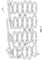
- FIGS. 1-3 A stent 100 disclosed herein is shown in FIGS. 1-3 .
- stent 100 is formed from a hollow wire 102.
- stent 100 is formed into a series of generally sinusoidal waves including generally straight segments 106 joined by bent segments or crowns 108 and form a generally tubular stent 100.
- the generally sinusoidal pattern is formed into a tube, as shown in FIG. 1 .
- selected crowns 108 of longitudinally adjacent sinusoids may be joined by, for example, welds 110.
- Stent 100 can be formed into any pattern suitable for use as a stent.
- stent 100 can be formed into patterns disclosed in U.S. Patent No. 4,800,082 to Gianturco , U.S. Patent No. 4,886,062 to Wiktor , U.S. Patent No. 5,133,732 to Wiktor , U.S. Patent No. 5,782,903 to Wiktor , U.S. Patent No. 6,136,023 to Boyle , and U.S. Patent No. 5,019,090 to Pinchuk .
- hollow wire 102 of stent 100 allows for a therapeutic substance or drug 112 to be deposited within the lumen 103 of hollow wire 102.
- hollow wire 102 is shown as generally having a circular cross-section, hollow wire 102 may be generally elliptical or rectangular in cross-section.
- Hollow wire 102 further includes cuts or openings 104 dispersed along its length to permit drug 112 to be released from lumen 103. Openings 104 may be disposed only on generally straight segments 106 of stent 100, only on crowns 108 of stent 100, or both generally straight segments 106 and crowns 108. Openings 104 may be sized and shaped as desired to control the elution rate of drug 112 from stent 100.
- Openings 104 may be varied along stent 100 in order to vary the quantity and/or rate of drug 112 being eluted from stent 100 at different portions of stent 100.
- Openings 104 may be, for example, 10-30 ⁇ m in diameter.
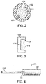
- Openings 104 may be provided only on an outwardly facing or ablumenal surface 116 of stent 100, as shown in FIG. 2 , only on the inwardly facing or lumenal surface 118 of stent 100, both surfaces, or may be provided anywhere along the circumference of wire 102.
- Ends 114 of wire 102 may be closed, as shown in FIG. 3 . Ends 114 may be closed by crimping excess material of wire 102 to close lumen 103. Closing ends 114 prevents drug 114 from prematurely releasing from ends 114. However, closing ends 114 is not required as drug 112 may be dried, provided within a polymer matrix, enclosed within a liner (not shown), or otherwise protected from premature release from ends 114. Further, ends 114 may be welded, crimped or otherwise connected to other portions of wire 102 such that the ends 114 are not free ends. Ends 114 may alternatively be provided as free ends.
- FIGS. 4-9 show a method for forming a hollow wire stent.
- step 200 is to provide a wire with an outer member and a central core member.
- These types of wire are sometimes referred to as core wires and may as be referred to as composite members.
- Core wire 170 hereof is formed of an outer member 102 and an inner or core member 120, as shown schematically in FIG. 4 .
- Outer member 102 becomes hollow wire 102 of stent 100, and thus has been labeled with the same reference number.
- Core wire 170 may be formed by any method known in the art, for example, a drawn filled tubing process, extruding the outer member over the inner member, or any other suitable method.
- core wires and methods of forming core wires can be found in U.S. Patent No. 5,630,840 to Mayer , U.S. Patent No. 6,248,190 to Stinson , U.S. Patent No. 6,497,709 to Heath , and U.S. Patent No. 7,101,392 to Heath .
- Outer member 102 can be any material that is suitable to be used as a stent. Outer member 102, as explained in more detail below, is the surviving material that will become hollow wire 102.
- outer member 102 may be a stainless steel, "MP35N,” “MP20N,” nickel titanium alloys such as Nitinol, magnesium, L605, or combinations thereof.
- MP35N and MP20N are trade names for alloys of cobalt, nickel, chromium and molybdenum available from standard Press Steel Co., Jenkintown, Pa. "MP35N” consists of 35% cobalt, 35% nickel, 20% chromium, and 10% molybdenum.
- MP20N consists of 50% cobalt, 20% nickel, 20% chromium, and 10% molybdenum.
- the requirements for the material of outer member 102 are that it be biocompatible, sufficiently resilient to be used as a stent, and that it survives the process for eliminating core member 120, as discussed in more detail below.
- Core member 120 may be a material that provides sufficient support to outer member 102 while the core wire is being bent into the stent pattern, as explained in more detail below.
- Core member 120 may be made of a material that is more ductile than the material of outer member 102 or may have a higher melting point than the material of outer member 102.
- core member 120 is made of a sacrificial material that can be removed by a process that does not damage the material of outer member 102. Examples of materials for core member 102 include tungsten (W), molybdenum (Mo), niobium (Nb), rhenium (Re), carbon (C), germanium (Ge), silicon (Si) and alloys thereof.
- Outer member 102 may have an outer diameter D 1 in the range of 0.0025 inch to 0.010 inch and wall thickness T in the range of 0.0005 inch or larger, depending on the application, for example, in what lumen or organ and for what purpose the stent is to be utilized.
- the values listed above are merely examples and other diameters and thicknesses may be used depending on, for example, the material used, the desired stent shape, and the purpose or location of the stent.
- step 210 is to shape the core wire 170 into the stent pattern.
- the stent pattern can be the pattern shown in FIG. 1 or any other suitable pattern formed from a wire. Further, although the order of all the steps is not critical, step 210 must be done prior to removing core member 120, as explained in more detail below. Shaping core wire 170 into the stent pattern while core member 120 is disposed within outer member 102 helps prevent kinking or other deformations from occurring in outer member 102. Shaping the core wire 170 into the stent pattern shown in FIG.
- core wire 170 generally includes the steps of forming core wire 170 into a two dimensional sinusoid pattern followed by wrapping the pattern around a mandrel, as known to those skilled in the art.
- the end result is a helical stent pattern formed onto a mandrel. Selected crowns 108 of the helical pattern are then welded together and the stent is removed from the mandrel.
- Step 220 shown in FIG. 9 is to provide openings 104 in outer member 102. Openings 104 may be laser cut, drilled, etched, or otherwise provided in outer member 102. Step 220 need not be performed after step 210, nor before step 230, although it is preferred to be before step 230, as explained in more detail below. If step 220 is performed after step 210, a cross-section of core wire 170 will include outer member 102, inner member 120, and an opening 104, as shown in FIG. 6 .
- Step 230 is to chemically etch away core member 120.
- Step 230 can be performed by any suitable process for removing core member 120 while preserving outer member 102.
- subjecting core wire 170 to xenon difluoride (XeF 2 ) gas at low pressure 1-6 Torr and relatively high temperature (approximately 150° C) causes the xenon difluoride (XeF 2 ) gas to react with a tantalum (Ta) core member 102 to form TaFs and Xe gases, which can be exhausted from lumen 103.
- XeF 2 xenon difluoride
- Ta tantalum
- Xenon difluoride (XeF 2 ) gas reacts similarly with a core member 120 made from tungsten, molybdenum, niobium, rhenium, carbon, germanium, and silicon. However, xenon difluoride (XeF 2 ) gas does not react with an outer member formed of MP35N. Accordingly, after step 230 is completed, outer member 102 remains and core member 120 has been removed, leaving the structure shown in FIG. 7 . As noted above, openings 104 do not need to be formed prior to the step of removing core member 120 as long as there is a way to expose core member 120 to the etchant. For example, ends 114 of the wire may be open or temporary ports may for formed through outer member 102 to expose core member 120 to the etchant.
- drug 112 may be injected into lumen 103 of outer member 102, as shown in step 240 of FIG. 10 .
- Stent 100 may be used conventionally in blood vessels of the body to support such a vessel after an angioplasty procedure. It is known that certain drugs eluted from stents may prevent restenosis or other complications associated with angioplasty or stents. Stent 100 may alternatively be used in other organs or tissues of the body for delivery of drugs to treat tumors, inflammation, nervous conditions, or other conditions that would be apparent to those skilled in the art.
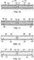
- FIGS. 10-13 show another hollow wire used to form a stent, wherein the hollow wire is formed from a first core wire 170 and a second core wire 170' coupled to each other in an end to end fashion. Only a portion of the wires are shown in FIGS. 10-13 . Further, more than two wires may be coupled to each other to form a stent.
- first core wire 170 includes a first outer member 102 and a first core member 120 disposed within a first lumen 103 of first outer member 102.
- second core wire 170' includes a second outer member 102' and a second core member 120' disposed within a second lumen 103' of outer member 102'.
- First core wire 170 and second core wire 170' may be coupled together through welding, soldering, adhesives, mechanical coupling, or other means known to those skilled in the art.
- First openings 104 are formed through first outer member 102 of first core wire 170 and second openings 104' are formed through second outer member 102' of second core wire 170', as shown in FIG. 11 .
- First and second openings 104, 104' may be the same size and shape or may be different sizes and/or shapes depending on the application. Openings 104, 104' may be formed as discussed above.
- First and second core wires 170, 170' are then exposed to a chemical etchant to remove first core member 120 and second core member 120', leaving the first and second outer members 102, 102', as shown in FIG. 12 .
- the chemical etchant can be as discussed above.
- a first drug 112 is then injected into first lumen 103 of first outer member 102 and a second drug is injected into second lumen 103' of second outer member 102', as shown in FIG. 13 .
- First drug 112 and second drug 112' may be different drugs or different concentrations of the same drug, depending on the application.
- Coupling multiple wires together to form a stent allows different drugs or different dosages of the same drug may be used for different portions of the stent.
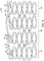
- a stent 300 shown in FIG. 14 may be used to treat a tumor wherein a greater concentration of drug 112 is required at a center portion 382 of stent 300 and lesser concentrations of drug 112 are required at proximal and distal portions 380, 384 of stent 300.
- a first core wire, a second wire, and a third wire core wire are coupled together end-to-end (114, 114', 114") as explained above with respect to FIG. 10 .
- the attached core wires are then shaped into a stent, such as the stent shown in FIG. 14 .
- the first core wire is the appropriate length to form proximal portion 380
- the second core wire is the appropriate length to form center portion 382
- the third core wire is the appropriate length to form distal portion 384.
- Holes 104, 104', 104" are formed through outer members 102, 102', 102" of the first, second, and third core wires, respectively.
- the core wires are exposed to a chemical etchant to remove the core members, as discussed above, and each outer member 102, 102', 102" is filled with a respective drug.
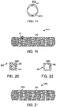
- a stent including hollow struts The method for forming a stent including hollow struts is described referring to FIGS. 15-22 .
- the previous examples, described to aid in the understanding the invention, have formed a core wire into a stent shape and then removed the core or inner member of the core wire, leaving a hollow wire shaped into a stent form.
- stents are also manufactured starting with a hollow, generally cylindrical thin-walled tube as shown, and then laser-cutting or etching away material from the tube to leave a generally cylindrical stent.
- the struts in such a method are the thickness of the wall of the tube.
- such struts are made to be hollow such that the struts can be filled with a therapeutic substance.
- a generally cylindrical, thin-walled tube 200 shown in FIG. 15 , is laser-cut, etched, or otherwise processed to remove material such that the remaining material is in the desired stent shape, as show in FIG. 16 .
- tube 200 is made of a sacrificial material similar to materials described herein for the core member of a core wire.
- struts 202 remaining from tube 200 are sized and spaced not as the final stent struts. Instead, struts 202 are sized and spaced as the inner lumen of hollow struts of the stent, as described in more detail below.
- Tubes 210 and 220 are made from a material desired for the final stent. The material also must be passive with respect to the process used to remove tube 200, as described in more detail below.
- the three-layer tube is processed so that the walls of tubes 210 and 220 surround struts 202 of tube 200, as shown in FIG. 18 .
- An example of such a process includes inserting a support rod in inner tube 210. A cylindrical press swages or compression welds the three tubes together. Other steps such as alloying can be used to remove latent stresses from the tubes.
- Struts 242 of stent 240 include an outer layer formed from the material of tubes 210 and 220, and an inner layer formed from the struts 202 of tube 200, as shown in FIG. 20 .
- Holes 244 are then laser-cut or otherwise drilled into struts 242, as shown in FIG. 21 .
- Stent 240 is then exposed to a process for removing struts 202 from struts 242.
- tube 200 and hence struts 202 may be made from tungsten, molybdenum, niobium, rhenium, carbon, germanium, or silicon and inner and outer tubes 210, 220 may be made from MP35N.
- Stent 240 may be exposed to xenon difluoride gas at low pressure and relatively high temperature such that it reacts with struts 202 to form a gas which can be exhausted through holes 244 or other ports cut into stent 240.
- Xenon difluoride does not react with MP35N. Accordingly, struts 242 remain and a lumen 246 is created in the void where struts 202 were dissolved away. Lumen 246 may then be filled with a therapeutic substance, as explained above.
- the alternative materials and processes for removing core members discussed below can be used in the process for making a stent described here to remove struts 202 from lumen 246 of struts 242.
- the therapeutic substance or drug may include, but is not limited to, antineoplastic, antimitotic, antiinflammatory, antiplatelet, anticoagulant, antifibrin, antithrombin, antiproliferative, antibiotic, antioxidant, and antiallergic substances as well as combinations thereof.
- antineoplastics and/or antimitotics include paclitaxel (e.g., TAXOL® by Bristol-Myers Squibb Co., Stamford, Conn.), docetaxel (e.g., Taxotere® from Aventis S.
- methotrexate methotrexate
- azathioprine azathioprine
- vincristine vinblastine
- fluorouracil doxorubicin hydrochloride
- doxorubicin hydrochloride e.g., Adriamycin® from Pharmacia & Upjohn, Peapack N.J.
- mitomycin e.g., Mutamycin® from Bristol-Myers Squibb Co., Stamford, Conn.
- antiplatelets examples include sodium heparin, low molecular weight heparins, heparinoids, hirudin, argatroban, forskolin, vapiprost, prostacyclin and prostacyclin analogues, dextran, D-phe-pro-arg-chloromethylketone (synthetic antithrombin), dipyridamole, glycoprotein IIb/IIIa platelet membrane receptor antagonist antibody, recombinant hirudin, and thrombin inhibitors such as AngiomaxTM (Biogen, Inc., Cambridge, Mass.).
- AngiomaxTM Biogen, Inc., Cambridge, Mass.
- cytostatic or antiproliferative agents examples include ABT-578 (a synthetic analog of rapamycin), rapamycin (sirolimus), zotarolimus, everolimus, angiopeptin, angiotensin converting enzyme inhibitors such as captopril (e.g., Capoten® and Capozide® from Bristol-Myers Squibb Co., Stamford, Conn.), cilazapril or lisinopril (e.g., Prinivil® and Prinzide® from Merck & Co., Inc., Whitehouse Station, N.J.), calcium channel blockers (such as nifedipine), colchicine, fibroblast growth factor (FGF) antagonists, fish oil (omega 3-fatty acid), histamine antagonists, lovastatin (an inhibitor of HMG-CoA reductase, a cholesterol lowering drug, brand name Mevacor® from Merck & Co., Inc., Whitehouse Station, N.J.),
- an antiallergic agent is permirolast potassium.
- Other therapeutic substances or agents that may be used include nitric oxide, alpha-interferon, genetically engineered epithelial cells, and dexamethasone.
- the therapeutic substance is a radioactive isotope for implantable device usage in radiotherapeutic procedures.
- radioactive isotopes include, but are not limited to, phosphorus (P 32 ), palladium (Pd 103 ), cesium (CS 131 ), Iridium (I 192 ) and iodine (I 125 ).
- a carrier may be used with the therapeutic substance or drug.
- suitable carriers include, but are not limited to, ethanol, acetone, tetrahydrofuran, dymethylsulfoxide, a combination thereof, or other suitable carriers known to those skilled in the art.
- a surfactant may be formulated with the drug and the solvent to aid elution of the drug.
- the hollow tubular structure is formed from a core wire or composite member including an outer member and a core member, wherein the core member is a sacrificial material that is removed after shaping the combined outer member/core member (core wire) into a desired shape.
- the outer member may be formed from a metal such as MP35N and the core member may be formed from tantalum.
- the core member is exposed to xenon difluoride gas in a vacuum which reacts with the core member material to form a gas that can be exhausted from the outer member.
- bromine trifluoride (BrF 3 ) or other interhalogen gases can be used instead of xenon difluoride to react with the core member.
- Ni nickel
- platinum iridium, titanium, or tantalum
- CO carbon monoxide
- the core member can be made from titanium or zirconium and exposed to iodine (I 2 ).
- the iodine reacts with the titanium or zirconium core member titanium iodide (TiI4) or zirconium iodide (ZrI4), which may be gases under the proper etching conditions known to those skilled in the art.
- TiI4 or zirconium iodide (ZrI4) which may be gases under the proper etching conditions known to those skilled in the art.
- outer member/core member combinations and chemical etchants include, but are not limited to: an MP35N outer member and a molybdenum core member with hydrogen peroxide (H 2 O 2 ) as the chemical etchant; a Nitinol (and other nickel alloys) or stainless steel outer member and a gold core member with potassium triiodide (KI 3 ) as the chemical etchant; and an aluminum alloy or stainless steel outer member and a copper core member with nitric acid as the chemical etchant.
- H 2 O 2 hydrogen peroxide
- KI 3 potassium triiodide
- a chemical etchant that reacts with the core member to dissolve the core member but does not react with an outer member that is suitable for use as the medical device could be used in this process.
- the core member is removed from the lumen of the outer member by solubilization.
- the core wire or composite member includes openings as discussed above. Placing the composite member in a liquid solvent in which the core member material is soluble but the outer member is not soluble will dissolve the core member material. The solvent with the core member material dissolved therein is then drained from the lumen of the outer member.
- the outer member material is a material commonly used for the medical device application and the lumen of the outer member is filled with salt or wax. After shaping the core wire into the desired shape, the shaped core wire is exposed to water or a non-polar solvent such as hexane, respectively. Core member dissolves in the solvent and is removed from the lumen.
- the outer member may be made of platinum and the core member may be made of metals that are dissolved by mercury, such as silver, gold, and copper.
- mercury such as silver, gold, and copper.
- tungsten may be used for the outer member and liquid gallium may be used as the solvent.
- the core member may be made of materials that are dissolved by liquid gallium, such as aluminum.
- sublimation is used to convert the core member from solid phase to gas phase to remove the core member material from the lumen of the outer member.
- the core member is formed from a material that when heated in a high vacuum converts from its solid phase to its gas phase.
- the outer member surrounding the core member is made from a material that does not sublimate or melt at the conditions to which the composite member (combined outer member and core member) is exposed.
- molybdenum or tungsten may be used as the outer member and chromium may be used as the core member. Heating chromium in a vacuum causes chromium to be vaporized by sublimation below its melting point temperature.
- the core member is made from a material with a lower melting point temperature than the material of the outer member. After the core wire is formed into the desired shape or otherwise processed, the core wire is heated to above the melting point temperature of the core member, but below the melting point temperature of the outer member. The core member melts into its liquid phase and is removed from the lumen of the outer member.
- the outer member should be selected such that heating the core wire above the melting point temperature of the core member does not negatively affect the physical properties of the outer member. Examples of outer members that may be used include, but are not limited to, titanium, nickel-chromium alloys such as MP35N, stainless steel, tantalum, and tungsten.
- core members that melt at lower temperatures than the outer members include, but are not limited to, magnesium, aluminum, zinc, gold, and silver.
- a magnesium core member is surrounded by an outer member formed of MP35N.
- the melting point for magnesium is approximately 650°C, while the melting point for MP35N is 1440°C.
- heating a core wire or composite member formed from an outer member formed from MP35N and a core member formed from magnesium to above 650°C, but below 1440°C melts the magnesium core member into a liquid which can be drained from the lumen of the outer member, leaving a hollow wire.
- the composite member may alternatively be heated above 1090°C, the boiling point of magnesium, but below 1440°C, such that the magnesium core member evaporates from the lumen of the MP35N outer member, leaving a hollow wire.
- FIG. 23 shows a cross-sectional view of a bone screw 300.
- Bone screw 300 includes a head 302 and a shank 304 including threads 306.
- Bone screw 300 further includes a reservoir or lumen 308 disposed within shank 304. Although reservoir 308 is shown only in shank 304, reservoir 208 can extend into head 302. Holes or openings 310 are provided in shank 304 from an outer surface of shank 304 to reservoir 308.
- a therapeutic substance or drug 312 is deposited within reservoir 308 such that therapeutic substance 312 elutes from reservoir 308 through holes 310 when bone screw 300 is implanted into a body.
- FIGS. 24-28 illustrate a method for making hollow, drug-eluting bone screw 300.
- an outer member 314 is extruded or otherwise provided over a core member 316. Ends 318 and 320 of outer member 314 may extend beyond the ends of core member 316, as shown.
- Outer member 314 may be formed of any suitable material for a bone screw. Examples of such materials include stainless steel, titanium, cobalt, chromium, tungsten, tantalum, molybedenum, and alloys thereof (e.g. MP35N).
- Core member 316 is formed of a sacrificial material such as those described above. Outer member 314 and core member 316 are selected depending on the process used to dissolve core member 316 from outer member 314, as described above.
- Ends 318, 320 of outer member 314 may then be pressed or otherwise processed such that ends 318, 320 surround core member 316, as shown in FIG. 25 .
- the outer member is then formed into the desired shape using techniques known to those skilled in the art, for example, using a four-axis CNC machine mill. Such process leaves outer member 314 in the shape of bone screw 300 with core member 316 enclosed therein, as shown in FIG. 26 .
- Holes 310 are then drilled, laser cut, or otherwise provided through outer member 314, as shown in FIG. 27 .
- Core member 316 is then exposed to a substance through holes 310 such that core member 316 dissolves and any byproduct material, such as a gas, is exhausted through holes 310, leaving reservoir 308, as shown in FIG. 28 .
- the processes discussed above for removing a core member from an outer member may be used to dissolve core member 316.
- Reservoir 308 may then be filled with therapeutic substance 312 through holes 310, thereby resulting in bone screw 300 shown in FIG
- Therapeutic substances 312 may include steroids, antibiotics, anti-inflammatory drugs, anti-proliferative compounds, antimyotic compounds, an antimitotic compounds, antimetabolite compounds, pain-relieving drugs, corticosteroids, angiostatic steroids, non-steroidal anti-inflammatory agents, bone in-growth promoting drugs such as hydroxylapatite and Simvastatin, and other substances as would be apparent to those skilled in the art. Further, carriers or controlled release agents may be added to the therapeutic substance.
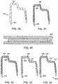
- FIG. 29 shows a schematic perspective view of a hollow, drug-eluting staple 400.
- Staple includes tips 402 and holes or openings 404 leading to a reservoir or lumen 410 (see FIGS. 33-34 ).
- a therapeutic substance or drug 412 ( FIG. 34 ) is deposited within reservoir 410 such that therapeutic substance 412 elutes from reservoir 410 through holes 404 when staple 400 is implanted into a body.
- FIGS. 30-34 illustrate a method for making hollow, drug-eluting staple 400.
- an outer member 406 is extruded or otherwise provided over a core member 408. The ends of outer member 406 may extend beyond the ends of core member 408, as shown.
- Outer member 406 may be formed of any suitable material for a staple. Examples of such materials include, but are not limited to, stainless steel, titanium, cobalt, chromium, tungsten, tantalum, molybedenum, and alloys thereof (e.g. MP35N).
- Core member 408 is formed of a sacrificial material such as those described above. Outer member 406 and core member 408 are selected depending on the process used to dissolve core member 408 from outer member 406, as described above.
- Outer member 406 and core member 408 may be pressed or otherwise processed such that the ends of outer member 406 surround core member 408, and the combination is then formed into the desired shape using techniques known to those skilled in the art. Such processes leaves outer member 406 in the shape of staple 400 with core member 408 enclosed therein, as shown in FIG. 31 . Holes 404 are then drilled, laser cut, or otherwise provided through outer member 406, as shown in FIG. 32 . Core member 408 is then exposed to a substance through holes 404 such that core member 408 dissolves and any byproduct material, such as a gas, is exhausted through holes 404, leaving reservoir 410, as shown in FIG. 33 . The processes discussed above for removing a core member from an outer member may be used to dissolve core member 408. Reservoir 410 may then be filled with therapeutic substance 412 through holes 410, thereby resulting in bone screw 300 shown in FIG. 34 .
- Therapeutic substances 412 may include steroids, antibiotics, anti-inflammatory drugs, anti-proliferative compounds, antimyotic compounds, an antimitotic compounds, antimetabolite compounds, pain-relieving drugs, corticosteroids, angiostatic steroids, non-steroidal anti-inflammatory agents, and other substances as would be apparent to those skilled in the art. Further, carriers or controlled release agents may be added to the therapeutic substance.
- FIG. 35 illustrates an example of a dual chamber, multi-programmable, implantable medical device (IMD) 500 and associated lead system for providing atrial and ventricular sensing functions, based on the programmed pacing and/or sensing mode and providing atrial or ventricular cardioversion therapies.
- IMD implantable medical device
- pacing pulses may be applied to the atrium and/or ventricle in response to the detection of the appropriate bradycardia condition by the IMD 500.
- the pacing and sensing functions may be effected through atrial and ventricular bipolar pace/sense electrode pairs at the ends of right atrial/superior vena cava (RA/SVC) and right ventricular (RV) leads 502 and 504, respectively.
- Leads 502 and 504 may be fixed in the right atrium 506 and right ventricle 508, respectively, that are electrically coupled to the circuitry of IMD 500 through a connector block 510.
- a coronary sinus (CS) lead 512 includes an elongated insulating lead body enclosing one elongated coiled wire conductor coupled to an elongated exposed coil wire CS cardioversion electrode 514.
- CS cardioversion electrode 514 illustrated in broken outline, is located within the coronary sinus of the heart 516.
- a connector end 518 having an exposed connector coupled to the coiled wire conductor and attached within the connector block 510 to connector block terminals in a manner well known in the art.
- the RA/SVC lead 502 may include an elongated insulating lead body carrying concentric, electrically isolated, coiled wire conductors separated from one another by tubular insulating sheaths.
- the lead body may be in an atrial J-shape in order to position its distal end in the right atrial appendage.
- An atrial pace/sense ring electrode 520 and an extendable helical, pace/sense electrode 522, mounted retractably within an insulating electrode head 524, are formed distally to the bend of the J-shape.
- Helical electrode 522 is extendable out of the electrode head 524 and can be screwed into the atrial appendage in a manner well known in the art.
- RA pace/sense electrodes 520, 522 are employed for atrial pacing and for near-field sensing of P-waves.
- An elongated, exposed coil, RA/SVC cardioversion electrode 526 is supported on RA lead 502 extending proximally to pace/sense ring electrode 520 and coupled to the third coiled wire conductor within the RA lead body.
- RA/SVC cardioversion electrode 526 preferably is 10 cm in length or greater and is configured to extend from within the SVC and toward the tricuspid valve 528.
- a bifurcated connector 530 which carries three exposed electrical connectors, each coupled to one of the coiled wire conductors, that are attached within the connector block 510 to connector block terminals in a manner well known in the art.
- the delivery of atrial cardioversion/ defibrillation therapies to the atria may be effected through selected combinations of intracardiac electrodes, e.g. the illustrated exemplary RA/SVC cardioversion electrode 526 and the CS cardioversion electrode 514.
- the exposed surface 532 of the outer housing or can of the IMD 500 may be selectively used as a can electrode 534.
- Can electrode 534 may serve as a subcutaneous remote cardioversion electrode in combination with one or more intracardiac cardioversion electrodes for cardioverting or defibrillating the atria.
- the RV lead 504 may include an elongated insulating lead body, enclosing at least three concentric, electrically isolated, coiled wire conductors, separated from one another by tubular insulating sheaths. Located adjacent the distal end of the RV lead 504 are a pace/sense ring electrode 536, and a helical, pace/sense electrode 538, mounted retractably within an insulating electrode head 540. Helical electrode 538 is extendable out of the electrode head 540 and can be screwed into the ventricular apex in a manner well known in the art. RV pace/sense electrodes 536, 538 are each coupled to a coiled wire conductor within the RV lead body and are employed for cardiac pacing in the ventricle and for sensing near-field R-waves.
- a distal segment of RV lead 504 also supports an elongated, exposed wire coil, cardioversion electrode 542.
- Cardioversion electrode 542 may be placed in the right ventricle 508 of heart 516 and connected to a further coiled wire conductor within the RV lead body.
- the ventricular cardioversion therapies may be delivered between further RV cardioversion electrodes in combination with cardioversion electrode 542 or between the cardioversion electrode and the can electrode 534 and/or the CS cardioversion electrode 514 or the RA/SVC cardioversion electrode 526.
- a bifurcated connector end 544 having a plurality of electrical connectors, each coupled to one of the coiled conductors in the RV lead body, that are attached within the connector block 510 to connector block terminals in a manner well known in the art.
- Helical electrodes such as helical electrode 538 are placed into the heart tissue, and deliver the electrical stimulation to the heart.
- An embodiment a helical or spiral electrode 538 is shown in FIGS. 36 and 37 .
- Electrode 538 includes a lumen 552 disposed therethrough and including a therapeutic substance 554 disposed therein. Holes or openings 550 disposed through an outer member 556 allow therapeutic substance 556 to elute to the targeted tissue.
- Electrode 538 may be formed as described above, that is: by forming a core wire formed of outer member 556 and a core member (not shown); shaping the core wire into the desired shaped; drilling or laser-cutting openings 550 through outer member 556; exposing the core member to an etchant such that the core member dissolves; and filling lumen 552 with therapeutic substance 554.
- Outer member can be any material that is commonly used for electrodes, such as stainless steel, MP35N, and platinum/iridium alloys.
- the core member is made from a sacrificial material and is selected based on the method used to dissolve the core member and the material selected for outer member 556.
- Therapeutic substance 552 may include anti-inflammatory drugs such as steroids, antibiotics, and anti-fungal materials. Further, carriers or controlled release agents may be added to the therapeutic substance.
Landscapes
- Health & Medical Sciences (AREA)
- Life Sciences & Earth Sciences (AREA)
- Heart & Thoracic Surgery (AREA)
- Engineering & Computer Science (AREA)
- Animal Behavior & Ethology (AREA)
- Veterinary Medicine (AREA)
- Public Health (AREA)
- General Health & Medical Sciences (AREA)
- Biomedical Technology (AREA)
- Cardiology (AREA)
- Vascular Medicine (AREA)
- Surgery (AREA)
- Nuclear Medicine, Radiotherapy & Molecular Imaging (AREA)
- Orthopedic Medicine & Surgery (AREA)
- Chemical & Material Sciences (AREA)
- Radiology & Medical Imaging (AREA)
- Epidemiology (AREA)
- Molecular Biology (AREA)
- Medicinal Chemistry (AREA)
- Pulmonology (AREA)
- Hematology (AREA)
- Inorganic Chemistry (AREA)
- Biophysics (AREA)
- Anesthesiology (AREA)
- Transplantation (AREA)
- Neurology (AREA)
- Optics & Photonics (AREA)
- Medical Informatics (AREA)
- Oral & Maxillofacial Surgery (AREA)
- Physics & Mathematics (AREA)
- Bioinformatics & Cheminformatics (AREA)
- Materials For Medical Uses (AREA)
- Media Introduction/Drainage Providing Device (AREA)
- Electrotherapy Devices (AREA)
- Surgical Instruments (AREA)
Claims (15)
- Verfahren zum Bilden eines Stents (240) mit hohlen Streben (242), die folgenden Schritte umfassend:Bereitstellen eines ersten Tubus (200), der aus einem ersten Material gefertigt ist, wobei der erste Tubus (200) eine Wand aufweist, die eine einen ersten inneren Durchmesser definierende Innenfläche und eine einen ersten äußeren Durchmesser definierende Außenfläche definiert;Entfernen von Abschnitten der Wand des ersten Tubus (200), sodass das übrige Material ein erstes Muster bildet;nach dem Entfernungsschritt Platzieren eines zweiten Tubus (220), der aus einem zweiten Material gefertigt ist, über dem ersten Tubus (200), wobei der zweite Tubus (220) eine Wand mit einer Innenfläche aufweist, die einen zweiten inneren Durchmesser definiert, der größer als der erste äußere Durchmesser ist;nach dem Entfernungsschritt Platzieren eines dritten Tubus (210), der aus dem zweiten Material gefertigt ist, innerhalb des ersten Tubus (200), wobei der dritte Tubus (210) eine Wand mit einer Außenfläche aufweist, die einen dritten äußeren Durchmesser definiert, der kleiner als der erste innere Durchmesser ist;Zusammendrücken des ersten, zweiten und dritten Tubus, sodass der zweite und dritte Tubus (210, 220) das übrige Material des ersten Tubus (200) umgeben;Entfernen von Abschnitten der Wände des zweiten Tubus (220) und des dritten Tubus (210) in einem zweiten Muster, das das übrige Material des ersten Tubus (200) und das Material des zweiten und dritten Tubus (210, 220), die das übrige Material des ersten Tubus (200) umgeben, erfasst;Bilden von Öffnungen (244) durch zumindest einen von dem ersten Tubus (200) und dem zweiten Tubus (220), um auf das übrige Material des ersten Tubus (200) zuzugreifen;Verarbeiten des übrigen Materials, sodass das übrige Material des ersten Tubus (200) entfernt wird, ohne das übrige Material des zweiten und dritten Tubus (210, 220) zu beschädigen, wodurch das übrige Material des zweiten und dritten Tubus (210, 220) als die hohlen Streben (242) des Stents (240) und ein Bereich, in dem das übrige Material des ersten Tubus (200) als ein Hohlraum (246) in den hohlen Streben (242) entfernt wurde, gelassen werden.
- Verfahren nach Anspruch 1, ferner umfassend den Schritt des Füllens des Hohlraums (246) mit einer therapeutischen Substanz; wobei die therapeutische Substanz optional aus der Gruppe ausgewählt ist, die aus antineoplastischen, antimitotischen, entzündungshemmenden, thrombozytenaggregationshemmenden, gerinnungshemmenden, Antifibrin-, Antithrombin-, antiproliferativen, antibiotischen, antioxidativen und antiallergenen Substanzen sowie Kombinationen davon besteht.
- Verfahren nach Anspruch 1, wobei der Schritt des Verarbeitens des übrigen Materials das Aussetzen des übrigen Materials gegenüber einem Ätzmittel umfasst, das mit dem ersten Material reagiert, um das erste Material zu entfernen, wobei das Ätzmittel nicht mit dem zweiten Material reagiert; wobei das Ätzmittel optional eine flüssige Chemikalie ist, die das erste Material auflöst.
- Verfahren nach Anspruch 3, wobei das zweite Material MP35N ist, das erste Material Molybdän ist und das Ätzmittel Wasserstoffperoxid ist.
- Verfahren nach Anspruch 3, wobei das zweite Material eine Nickel-Titan-Legierung oder Edelstahl ist, das erste Material Gold ist und das Ätzmittel Kaliumtriiodid ist.
- Verfahren nach Anspruch 3, wobei das zweite Material eine Aluminiumlegierung oder Edelstahl ist, das erste Material Kupfer ist und das Ätzmittel Salpetersäure ist.
- Verfahren nach Anspruch 3, wobei das Ätzmittel ein Gas ist.
- Verfahren nach Anspruch 7, wobei das zweite Material MP35N ist, das erste Material aus der Gruppe ausgewählt ist, die aus Tantal, Wolfram, Molybdän, Niobium, Rhenium, Kohlenstoff, Germanium und Silizium besteht und das Ätzmittel Xenondifluorid oder Bromtrifluorid ist.
- Verfahren nach Anspruch 7, wobei das zweite Material aus der Gruppe ausgewählt ist, die aus Platin, Iridium, Titan und Tantal besteht, das erste Material Nickel ist und das Ätzmittel Kohlenmonoxid ist.
- Verfahren nach Anspruch 7, wobei das zweite Material Edelstahl oder nickelbasierte Legierungen ist, das erste Material Titan oder Zirkonium ist und das Ätzmittel Jod ist.
- Verfahren nach Anspruch 3, wobei das erste Material in dem Ätzmittel löslich ist und das zweite Material nicht in dem Ätzmittel löslich ist.
- Verfahren nach Anspruch 11, wobei das zweite Material Platin ist, das erste Material aus der Gruppe ausgewählt ist, die aus Silber, Gold und Kupfer besteht und das Ätzmittel Quecksilber umfasst.
- Verfahren nach Anspruch 11, wobei das zweite Material Wolfram ist, das erste Material Aluminium ist und das Ätzmittel flüssiges Gallium umfasst.
- Verfahren nach Anspruch 1, wobei der Schritt des Verarbeitens des übrigen Materials das Erwärmen des übrigen Materials auf eine Temperatur zum Sublimieren des ersten Materials umfasst; wobei das zweite Material optional Molybdän oder Wolfram umfasst, das erste Material Chrom umfasst und der Verarbeitungsschritt das Erwärmen des übrigen Materials in einem Vakuum auf eine Temperatur, oberhalb derer Chrom sublimiert, umfasst.
- Verfahren nach Anspruch 1, wobei der Schritt des Verarbeitens des übrigen Materials das Erwärmen des übrigen Materials auf eine Temperatur zum Schmelzen des ersten Materials umfasst; wobei das zweite Material optional aus der Gruppe ausgewählt ist, die aus MP35N, Titan, Tantal und Wolfram besteht, das erste Material aus der Gruppe ausgewählt ist, die aus Magnesium, Aluminium, Zink, Gold und Silber besteht und der Verarbeitungsschritt das Erwärmen des übrigen Materials über eine Schmelzpunkttemperatur des ersten Materials und unter eine Schmelzpunkttemperatur des zweiten Materials umfasst.
Applications Claiming Priority (3)
| Application Number | Priority Date | Filing Date | Title |
|---|---|---|---|
| US12/500,359 US9283305B2 (en) | 2009-07-09 | 2009-07-09 | Hollow tubular drug eluting medical devices |
| PCT/US2010/039087 WO2011005451A2 (en) | 2009-07-09 | 2010-06-17 | Hollow tubular drug eluting medical devices |
| EP10729984.4A EP2451497B1 (de) | 2009-07-09 | 2010-06-17 | Hohle tubusförmige medikamentenbeschichtete vorrichtungen |
Related Parent Applications (1)
| Application Number | Title | Priority Date | Filing Date |
|---|---|---|---|
| EP10729984.4A Division EP2451497B1 (de) | 2009-07-09 | 2010-06-17 | Hohle tubusförmige medikamentenbeschichtete vorrichtungen |
Publications (2)
| Publication Number | Publication Date |
|---|---|
| EP3199185A1 EP3199185A1 (de) | 2017-08-02 |
| EP3199185B1 true EP3199185B1 (de) | 2018-11-14 |
Family
ID=42667935
Family Applications (2)
| Application Number | Title | Priority Date | Filing Date |
|---|---|---|---|
| EP17157525.1A Active EP3199185B1 (de) | 2009-07-09 | 2010-06-17 | Hohle tubusförmige medikamentenbeschichtete vorrichtungen |
| EP10729984.4A Active EP2451497B1 (de) | 2009-07-09 | 2010-06-17 | Hohle tubusförmige medikamentenbeschichtete vorrichtungen |
Family Applications After (1)
| Application Number | Title | Priority Date | Filing Date |
|---|---|---|---|
| EP10729984.4A Active EP2451497B1 (de) | 2009-07-09 | 2010-06-17 | Hohle tubusförmige medikamentenbeschichtete vorrichtungen |
Country Status (5)
| Country | Link |
|---|---|
| US (2) | US9283305B2 (de) |
| EP (2) | EP3199185B1 (de) |
| JP (2) | JP5978543B2 (de) |
| CN (2) | CN105726177B (de) |
| WO (1) | WO2011005451A2 (de) |
Families Citing this family (30)
| Publication number | Priority date | Publication date | Assignee | Title |
|---|---|---|---|---|
| US9119736B2 (en) | 2012-01-27 | 2015-09-01 | Medtronic Vascular, Inc. | Hollow drug-filled stent and method of forming hollow drug-filled stent |
| US9345596B2 (en) | 2012-02-23 | 2016-05-24 | Medtronic Vascular, Inc. | Method of forming a nitinol stent |
| US9649208B2 (en) | 2012-04-13 | 2017-05-16 | Medtronic Vascular, Inc. | Hollow drug-filled stent and method of forming hollow drug-filled stent |
| US8998977B2 (en) * | 2012-04-13 | 2015-04-07 | Medtronic Vascular, Inc. | Hollow drug-filled stent and method of forming hollow drug-filled stent |
| US9549832B2 (en) | 2012-04-26 | 2017-01-24 | Medtronic Vascular, Inc. | Apparatus and methods for filling a drug eluting medical device via capillary action |
| US9204982B2 (en) | 2012-04-26 | 2015-12-08 | Medtronic Vascular, Inc. | Apparatus and methods for filling a drug eluting medical device via capillary action |
| US9155645B2 (en) | 2012-06-26 | 2015-10-13 | Abbott Cardiovascular Systems Inc. | Implantable prosthesis with radiopaque particles and method of making same |
| US9149375B2 (en) | 2012-06-26 | 2015-10-06 | Abbott Cardiovascular Systems Inc. | Radiopaque drug-filled prosthesis and method of making same |
| WO2014003847A1 (en) | 2012-06-26 | 2014-01-03 | Abbott Cardiovascular Systems Inc. | Implantable prosthesis with hollow struts and passivating coating, and method of making same |
| US9681965B2 (en) * | 2012-07-31 | 2017-06-20 | Cook Medical Technologies Llc | Barbed anchors for attachment to endoluminal prosthesis |
| EP2967938B1 (de) | 2013-03-14 | 2017-03-01 | Medtronic Vascular Inc. | Verfahren zur herstellung eines stents und dadurch hergestellter stent |
| CN103315833A (zh) * | 2013-06-17 | 2013-09-25 | 苏州爱瑞德医疗科技有限公司 | 一种靶向给药管材编织血管支架 |
| US10085859B2 (en) * | 2013-07-03 | 2018-10-02 | Medtronic Vascular, Inc. | Methods of manufacturing a drug-eluting stent |
| WO2015088972A1 (en) * | 2013-12-09 | 2015-06-18 | Ryan Kendall Pierce | Devices and methods for treating cardiovascular and metabolic disease |
| EP3269010A1 (de) | 2015-03-12 | 2018-01-17 | Cardiac Pacemakers, Inc. | Elektrischer verbinder und verfahren zur herstellung eines elektrischen verbinders |
| WO2017015571A1 (en) | 2015-07-23 | 2017-01-26 | Novaflux, Inc. | Implants and constructs including hollow fibers |
| CN106955374B (zh) * | 2016-01-08 | 2019-11-08 | 先健科技(深圳)有限公司 | 植入式器械 |
| WO2017214434A1 (en) | 2016-06-10 | 2017-12-14 | Medtronic Vascular Inc. | Drug-eluting stent formed from a deformable hollow strut for a customizable elution rate |
| EP3538033B1 (de) * | 2016-11-10 | 2022-08-03 | Medtronic Vascular Inc. | Medikamentengefüllte stents zur verhinderung von gefässmikroläsionen und verfahren zur herstellung davon |
| CN109922759A (zh) | 2016-11-10 | 2019-06-21 | 美敦力瓦斯科尔勒公司 | 具有用于增加的内腔表面积的细丝的药物填充支架及其制造方法 |
| US10226367B2 (en) | 2016-12-19 | 2019-03-12 | Medtronic Vascular, Inc. | Apparatus and methods for filling a drug eluting medical device via capillary action |
| CN107095728A (zh) * | 2017-05-19 | 2017-08-29 | 东莞颠覆产品设计有限公司 | 管腔内载药支架 |
| CN111032103B (zh) * | 2017-09-21 | 2021-12-21 | 泰尔茂株式会社 | 药物涂层的形成方法及形成装置 |
| CN108125738A (zh) * | 2017-12-21 | 2018-06-08 | 潍坊医学院 | 一种心血管支架 |
| EP3810033B1 (de) * | 2018-06-19 | 2024-11-13 | Medtronic Vascular, Inc. | Modulare stentvorrichtung für mehrere gefässe |
| EP3950045B1 (de) * | 2020-08-04 | 2025-01-01 | Heraeus Medevio GmbH & Co. KG | Ringelektrode für eine medizinische vorrichtung |
| CN116546942A (zh) | 2020-09-07 | 2023-08-04 | 前沿生物公司 | 用于创建具有特定血管应用的导管的对象的系统和方法 |
| US11925544B2 (en) | 2020-10-13 | 2024-03-12 | Shanghai Tendfo Medical Technologies Co. Ltd. | Pulmonary artery stent |
| WO2022077781A1 (zh) * | 2020-10-13 | 2022-04-21 | 上海腾复医疗科技有限公司 | 注药支架及包含其的注药溶栓系统 |
| US11998192B2 (en) | 2021-05-10 | 2024-06-04 | Cilag Gmbh International | Adaptive control of surgical stapling instrument based on staple cartridge type |
Family Cites Families (133)
| Publication number | Priority date | Publication date | Assignee | Title |
|---|---|---|---|---|
| US1727574A (en) * | 1922-03-31 | 1929-09-10 | Albert D Tibbals | Staple strip and method of making same |
| US2153936A (en) | 1938-05-21 | 1939-04-11 | Gulf Research Development Co | Machine for continuously forming curved wire forms |
| US4531933A (en) | 1982-12-07 | 1985-07-30 | C. R. Bard, Inc. | Helical ureteral stent |
| US4643716A (en) | 1984-09-26 | 1987-02-17 | The Kendall Company | Multi-size ureteral stent |
| US4720384A (en) | 1985-05-03 | 1988-01-19 | E. I. Du Pont De Nemours And Company | Manufacture of hollow fine tubular drug delivery systems |
| US4763647A (en) | 1987-01-06 | 1988-08-16 | C. R. Bard, Inc. | Dual coil steerable guidewire |
| US4800882A (en) | 1987-03-13 | 1989-01-31 | Cook Incorporated | Endovascular stent and delivery system |
| US4800082A (en) * | 1987-03-23 | 1989-01-24 | The Dow Chemical Company | Sustained release microbiological control composition |
| US4813925A (en) | 1987-04-21 | 1989-03-21 | Medical Engineering Corporation | Spiral ureteral stent |
| US5154705A (en) | 1987-09-30 | 1992-10-13 | Lake Region Manufacturing Co., Inc. | Hollow lumen cable apparatus |
| US5133732A (en) * | 1987-10-19 | 1992-07-28 | Medtronic, Inc. | Intravascular stent |
| US4886062A (en) * | 1987-10-19 | 1989-12-12 | Medtronic, Inc. | Intravascular radially expandable stent and method of implant |
| US5782903A (en) * | 1987-10-19 | 1998-07-21 | Medtronic, Inc. | Intravascular stent and method |
| US4913683A (en) | 1988-07-05 | 1990-04-03 | Medical Engineering Corporation | Infusion stent system |
| US5019090A (en) * | 1988-09-01 | 1991-05-28 | Corvita Corporation | Radially expandable endoprosthesis and the like |
| US5063935A (en) | 1989-04-27 | 1991-11-12 | C. R. Bard, Inc. | Catheter guidewire with varying radiopacity |
| ATE120377T1 (de) * | 1990-02-08 | 1995-04-15 | Howmedica | Aufblasbarer dilatator. |
| US5345945A (en) | 1990-08-29 | 1994-09-13 | Baxter International Inc. | Dual coil guidewire with radiopaque distal tip |
| DE4104702C2 (de) | 1991-02-15 | 1996-01-18 | Malte Neuss | Implantate für Organwege in Wendelform |
| US5605162A (en) | 1991-10-15 | 1997-02-25 | Advanced Cardiovascular Systems, Inc. | Method for using a variable stiffness guidewire |
| US6497709B1 (en) * | 1992-03-31 | 2002-12-24 | Boston Scientific Corporation | Metal medical device |
| US7101392B2 (en) * | 1992-03-31 | 2006-09-05 | Boston Scientific Corporation | Tubular medical endoprostheses |
| US5306250A (en) * | 1992-04-02 | 1994-04-26 | Indiana University Foundation | Method and apparatus for intravascular drug delivery |
| US5630840A (en) * | 1993-01-19 | 1997-05-20 | Schneider (Usa) Inc | Clad composite stent |
| US5538735A (en) | 1993-02-19 | 1996-07-23 | Ahn; Sam S. | Method of making a drug delivery system using hollow fibers |
| US20020055710A1 (en) | 1998-04-30 | 2002-05-09 | Ronald J. Tuch | Medical device for delivering a therapeutic agent and method of preparation |
| US5716410A (en) | 1993-04-30 | 1998-02-10 | Scimed Life Systems, Inc. | Temporary stent and method of use |
| US5891108A (en) | 1994-09-12 | 1999-04-06 | Cordis Corporation | Drug delivery stent |
| US5569197A (en) | 1994-12-21 | 1996-10-29 | Schneider (Usa) Inc | Drug delivery guidewire |
| WO1996026682A1 (en) | 1995-02-27 | 1996-09-06 | Instent, Inc. | Hollow stent |
| US5843117A (en) | 1996-02-14 | 1998-12-01 | Inflow Dynamics Inc. | Implantable vascular and endoluminal stents and process of fabricating the same |
| EP0801934B1 (de) * | 1996-04-16 | 2000-06-14 | Medtronic, Inc. | Geschweisster sinuswellenförmiger Stent |
| US6783543B2 (en) | 2000-06-05 | 2004-08-31 | Scimed Life Systems, Inc. | Intravascular stent with increasing coating retaining capacity |
| US5670161A (en) | 1996-05-28 | 1997-09-23 | Healy; Kevin E. | Biodegradable stent |
| CA2213015A1 (en) | 1996-08-23 | 1998-02-23 | Arterial Vascular Engineering, Inc. | A profiled stent and method of manufacture |
| US6099561A (en) | 1996-10-21 | 2000-08-08 | Inflow Dynamics, Inc. | Vascular and endoluminal stents with improved coatings |
| US5824045A (en) | 1996-10-21 | 1998-10-20 | Inflow Dynamics Inc. | Vascular and endoluminal stents |
| ZA9710342B (en) | 1996-11-25 | 1998-06-10 | Alza Corp | Directional drug delivery stent and method of use. |
| US5980564A (en) | 1997-08-01 | 1999-11-09 | Schneider (Usa) Inc. | Bioabsorbable implantable endoprosthesis with reservoir |
| CN1244794A (zh) | 1997-11-06 | 2000-02-16 | 奥尔班公司 | 用于药物释放的稳定的干燥药物组合物及其制备方法 |
| US6022369A (en) | 1998-02-13 | 2000-02-08 | Precision Vascular Systems, Inc. | Wire device with detachable end |
| US20040254635A1 (en) | 1998-03-30 | 2004-12-16 | Shanley John F. | Expandable medical device for delivery of beneficial agent |
| US7208010B2 (en) | 2000-10-16 | 2007-04-24 | Conor Medsystems, Inc. | Expandable medical device for delivery of beneficial agent |
| US7208011B2 (en) | 2001-08-20 | 2007-04-24 | Conor Medsystems, Inc. | Implantable medical device with drug filled holes |
| US6248190B1 (en) * | 1998-06-15 | 2001-06-19 | Scimed Life Systems, Inc. | Process of making composite stents with gold alloy cores |
| US6652581B1 (en) | 1998-07-07 | 2003-11-25 | Boston Scientific Scimed, Inc. | Medical device with porous surface for controlled drug release and method of making the same |
| US6358276B1 (en) | 1998-09-30 | 2002-03-19 | Impra, Inc. | Fluid containing endoluminal stent |
| US6547814B2 (en) | 1998-09-30 | 2003-04-15 | Impra, Inc. | Selective adherence of stent-graft coverings |
| US6063101A (en) | 1998-11-20 | 2000-05-16 | Precision Vascular Systems, Inc. | Stent apparatus and method |
| US6558422B1 (en) | 1999-03-26 | 2003-05-06 | University Of Washington | Structures having coated indentations |
| US6478778B1 (en) | 1999-05-28 | 2002-11-12 | Precision Vascular Systems, Inc. | Apparatus for delivering fluids to blood vessels, body cavities, and the like |
| EP1229901B1 (de) | 1999-11-17 | 2009-03-18 | Boston Scientific Limited | Miniaturisierte vorrichtungen zur abgabe von molekülen in einer trägerflüssigkeit |
| EP1132058A1 (de) | 2000-03-06 | 2001-09-12 | Advanced Laser Applications Holding S.A. | Intravaskuläre Prothese |
| US8252044B1 (en) | 2000-11-17 | 2012-08-28 | Advanced Bio Prosthestic Surfaces, Ltd. | Device for in vivo delivery of bioactive agents and method of manufacture thereof |
| US20030021825A1 (en) | 2000-06-28 | 2003-01-30 | Pathak Chandrashekhar P. | Cleaning of medical devices with supercritical fluids |
| US6585765B1 (en) | 2000-06-29 | 2003-07-01 | Advanced Cardiovascular Systems, Inc. | Implantable device having substances impregnated therein and a method of impregnating the same |
| US7037330B1 (en) * | 2000-10-16 | 2006-05-02 | Scimed Life Systems, Inc. | Neurovascular stent and method |
| US6758859B1 (en) | 2000-10-30 | 2004-07-06 | Kenny L. Dang | Increased drug-loading and reduced stress drug delivery device |
| US9107605B2 (en) | 2000-11-17 | 2015-08-18 | Advanced Bio Prosthetic Surfaces, Ltd., A Wholly Owned Subsidiary Of Palmaz Scientific, Inc. | Device for in vivo delivery of bioactive agents and method of manufacture thereof |
| US10398830B2 (en) | 2000-11-17 | 2019-09-03 | Vactronix Scientific, Llc | Device for in vivo delivery of bioactive agents and method of manufacture thereof |
| US6641607B1 (en) | 2000-12-29 | 2003-11-04 | Advanced Cardiovascular Systems, Inc. | Double tube stent |
| US6752829B2 (en) | 2001-01-30 | 2004-06-22 | Scimed Life Systems, Inc. | Stent with channel(s) for containing and delivering a biologically active material and method for manufacturing the same |
| US20040073294A1 (en) | 2002-09-20 | 2004-04-15 | Conor Medsystems, Inc. | Method and apparatus for loading a beneficial agent into an expandable medical device |
| US9216239B2 (en) | 2001-06-08 | 2015-12-22 | Leo Rubin | Medical device for intra-lumenal delivery of pharmaceutical agents |
| ATE330564T1 (de) | 2001-07-20 | 2006-07-15 | Sorin Biomedica Cardio Srl | Stent |
| JP2005508671A (ja) | 2001-07-26 | 2005-04-07 | アバンテク バスキュラー コーポレーション | 治療に有効な薬剤の送達 |
| US20060224234A1 (en) | 2001-08-29 | 2006-10-05 | Swaminathan Jayaraman | Drug eluting structurally variable stent |
| US20060004437A1 (en) | 2001-08-29 | 2006-01-05 | Swaminathan Jayaraman | Structurally variable stents |
| TWI233811B (en) | 2001-09-25 | 2005-06-11 | Ind Tech Res Inst | Sustained release micro-porous hollow fiber and method of manufacturing the same |
| EP1310242A1 (de) | 2001-11-13 | 2003-05-14 | SORIN BIOMEDICA CARDIO S.p.A. | Träger und Kit für endoluminale Wirkstoffabgabe |
| US7014654B2 (en) | 2001-11-30 | 2006-03-21 | Scimed Life Systems, Inc. | Stent designed for the delivery of therapeutic substance or other agents |
| US20030114919A1 (en) * | 2001-12-10 | 2003-06-19 | Mcquiston Jesse | Polymeric stent with metallic rings |
| US6939374B2 (en) | 2001-12-21 | 2005-09-06 | Scimed Life Systems, Inc. | Stents, stenting systems, and related methods for agent delivery |
| US20030212449A1 (en) * | 2001-12-28 | 2003-11-13 | Cox Daniel L. | Hybrid stent |
| EP1348402A1 (de) | 2002-03-29 | 2003-10-01 | Advanced Laser Applications Holding S.A. | Intraluminale, radial ausweitbare, duchlöcherte Endoprothese zur Zufuhr von Medikamenten |
| US7122048B2 (en) | 2002-05-03 | 2006-10-17 | Scimed Life Systems, Inc. | Hypotube endoluminal device |
| AU2003250913A1 (en) | 2002-07-08 | 2004-01-23 | Abbott Laboratories Vascular Enterprises Limited | Drug eluting stent and methods of manufacture |
| AU2003303288B2 (en) | 2002-08-16 | 2006-12-07 | Microchips, Inc. | Controlled release device and method |
| EP1391184A1 (de) * | 2002-08-16 | 2004-02-25 | Endosense Sàrl | Dehnbare, mehrschichtige röhrenförmige Struktur und Verfahren zu deren Herstellung |
| US7400931B2 (en) | 2002-09-18 | 2008-07-15 | Cardiac Pacemakers, Inc. | Devices and methods to stimulate therapeutic angiogenesis for ischemia and heart failure |
| US7044965B1 (en) | 2002-12-13 | 2006-05-16 | Spielberg Theodore E | Therapeutic cellular stent |
| US20040147998A1 (en) | 2003-01-24 | 2004-07-29 | Nolting John E. | Differentially coated stent |
| US7458985B2 (en) | 2003-01-27 | 2008-12-02 | Frank Madda | Spiral stent assembly |
| US7182735B2 (en) | 2003-02-26 | 2007-02-27 | Scimed Life Systems, Inc. | Elongated intracorporal medical device |
| EP2289571B1 (de) | 2003-03-28 | 2016-08-03 | Innovational Holdings, LLC | Implantierbare medizinische vorrichtung mit kontinuerlichem gradienten einer therapeutischen substanz |
| US20050070996A1 (en) | 2003-04-08 | 2005-03-31 | Dinh Thomas Q. | Drug-eluting stent for controlled drug delivery |
| US7288084B2 (en) | 2003-04-28 | 2007-10-30 | Boston Scientific Scimed, Inc. | Drug-loaded medical device |
| WO2004110502A2 (en) | 2003-06-09 | 2004-12-23 | Macropore Biosurgery, Inc. | Helical endoluminal stent and related methods |
| CA2536961A1 (en) | 2003-08-14 | 2005-02-24 | Blue Medical Devices B.V. | Endoluminal prosthesis comprising a therapeutic agent |
| US20050055080A1 (en) | 2003-09-05 | 2005-03-10 | Naim Istephanous | Modulated stents and methods of making the stents |
| US20050060020A1 (en) | 2003-09-17 | 2005-03-17 | Scimed Life Systems, Inc. | Covered stent with biologically active material |
| US9278015B2 (en) | 2003-10-16 | 2016-03-08 | Minvasys | Catheter system for stenting and drug treatment of bifurcated vessels |
| US7744644B2 (en) | 2004-03-19 | 2010-06-29 | Boston Scientific Scimed, Inc. | Medical articles having regions with polyelectrolyte multilayer coatings for regulating drug release |
| US7989490B2 (en) | 2004-06-02 | 2011-08-02 | Cordis Corporation | Injectable formulations of taxanes for cad treatment |
| EP1600534A1 (de) | 2004-05-27 | 2005-11-30 | Shenzhen Yang Qian Material Application Technology Co., Ltd. | Verfahren zur Herstellung von Kern-Mantel-Kompositfasern |
| DE102004048991B4 (de) * | 2004-10-04 | 2010-01-28 | Biotronik Crm Patent Ag | Elektrodenleitung |
| US7419681B2 (en) | 2004-12-02 | 2008-09-02 | Bioretec, Ltd. | Method to enhance drug release from a drug-releasing material |
| US8323333B2 (en) | 2005-03-03 | 2012-12-04 | Icon Medical Corp. | Fragile structure protective coating |
| US20070043423A1 (en) | 2005-08-10 | 2007-02-22 | Med Institute Inc. | Intraluminal device with a hollow structure |
| US20070055352A1 (en) | 2005-09-07 | 2007-03-08 | Wendy Naimark | Stent with pockets for containing a therapeutic agent |
| GB0522569D0 (en) | 2005-11-04 | 2005-12-14 | Univ Bath | Biocompatible drug delivery device |
| US20070168021A1 (en) | 2006-01-17 | 2007-07-19 | Holmes David R Jr | Porous three dimensional nest scaffolding |
| US20070173923A1 (en) | 2006-01-20 | 2007-07-26 | Savage Douglas R | Drug reservoir stent |
| JP3121578U (ja) | 2006-03-02 | 2006-05-18 | 怪怪貿易有限公司 | トイガンのボルトスライド機構 |
| US8815275B2 (en) | 2006-06-28 | 2014-08-26 | Boston Scientific Scimed, Inc. | Coatings for medical devices comprising a therapeutic agent and a metallic material |
| US20080033522A1 (en) * | 2006-08-03 | 2008-02-07 | Med Institute, Inc. | Implantable Medical Device with Particulate Coating |
| US9198749B2 (en) | 2006-10-12 | 2015-12-01 | C. R. Bard, Inc. | Vascular grafts with multiple channels and methods for making |
| US20080276935A1 (en) | 2006-11-20 | 2008-11-13 | Lixiao Wang | Treatment of asthma and chronic obstructive pulmonary disease with anti-proliferate and anti-inflammatory drugs |
| US7575593B2 (en) | 2007-01-30 | 2009-08-18 | Medtronic Vascular, Inc. | Implantable device with reservoirs for increased drug loading |
| US8221496B2 (en) | 2007-02-01 | 2012-07-17 | Cordis Corporation | Antithrombotic and anti-restenotic drug eluting stent |
| WO2008098924A2 (en) * | 2007-02-13 | 2008-08-21 | Cinvention Ag | Medical devices with extended or multiple reservoirs |
| EP2111193A1 (de) | 2007-02-13 | 2009-10-28 | Cinvention Ag | Implantate und stents mit reservoir |
| US20080234809A1 (en) | 2007-03-23 | 2008-09-25 | Medtronic Vascular, Inc. | Stent Graft System With Injection Tube |
| US20080249599A1 (en) | 2007-04-05 | 2008-10-09 | Medtronic Vascular, Inc. | Stent With Therapeutic Agent Delivery Structures in Low Strain Regions |
| TW200840553A (en) | 2007-04-12 | 2008-10-16 | Jung-Tang Huang | A fabrication method for drug-eluting stent with medicine-compatible filling mechanism |
| US8328867B2 (en) | 2007-06-08 | 2012-12-11 | Medtronic Vascular, Inc. | Drug loaded implantable medical device |
| DE102007034041A1 (de) | 2007-07-20 | 2009-01-22 | Biotronik Vi Patent Ag | Medikamentendepots für medizinische Implantate |
| US20090035351A1 (en) | 2007-07-20 | 2009-02-05 | Medtronic Vascular, Inc. | Bioabsorbable Hypotubes for Intravascular Drug Delivery |
| US20090024209A1 (en) | 2007-07-20 | 2009-01-22 | Medtronic Vascular, Inc. | Hypotubes for Intravascular Drug Delivery |
| US20090157172A1 (en) | 2007-07-24 | 2009-06-18 | Boston Scientific Scrimed, Inc. | Stents with polymer-free coatings for delivering a therapeutic agent |
| US7901726B2 (en) | 2007-08-31 | 2011-03-08 | Boston Scientific Scimed, Inc. | Porous medical articles for therapeutic agent delivery |
| US20090076591A1 (en) | 2007-09-19 | 2009-03-19 | Boston Scientific Scimed, Inc. | Stent Design Allowing Extended Release of Drug and/or Enhanced Adhesion of Polymer to OD Surface |
| US20090093871A1 (en) | 2007-10-08 | 2009-04-09 | Medtronic Vascular, Inc. | Medical Implant With Internal Drug Delivery System |
| US8016880B2 (en) | 2007-11-16 | 2011-09-13 | Medtronic Vascular, Inc. | Stent having spiral channel for drug delivery |
| ATE521309T1 (de) | 2008-01-24 | 2011-09-15 | Boston Scient Scimed Inc | Stent zum ausbringen eines therapeutischen mittels von einer seitenfläche einer stentstrebe |
| US8114151B2 (en) | 2008-05-08 | 2012-02-14 | Boston Scientific Scimed, Inc. | Stent with tabs and holes for drug delivery |
| DE102008002397A1 (de) | 2008-06-12 | 2009-12-17 | Biotronik Vi Patent Ag | Implantierbare Vorrichtung |
| US20090319026A1 (en) | 2008-06-20 | 2009-12-24 | Boston Scientific Scimed, Inc. | Composite Stent with Reservoirs for Drug Delivery and Methods of Manufacturing |
| DE102008040356A1 (de) | 2008-07-11 | 2010-01-14 | Biotronik Vi Patent Ag | Stent mit biodegradierbaren Stentstreben und Wirkstoffdepots |
| US7951193B2 (en) | 2008-07-23 | 2011-05-31 | Boston Scientific Scimed, Inc. | Drug-eluting stent |
| JP2011530347A (ja) | 2008-08-07 | 2011-12-22 | エクソジェネシス コーポレーション | 薬物送達システムおよびその薬物送達システムの製造方法 |
| EP2349122A1 (de) | 2008-09-12 | 2011-08-03 | Boston Scientific Scimed, Inc. | Schichtweise stentherstellung |
| US20100082096A1 (en) | 2008-09-30 | 2010-04-01 | Boston Scientific Scimed, Inc. | Tailored Luminal & Abluminal Drug Elution |
-
2009
- 2009-07-09 US US12/500,359 patent/US9283305B2/en active Active
-
2010
- 2010-06-17 CN CN201610085534.8A patent/CN105726177B/zh active Active
- 2010-06-17 JP JP2012519561A patent/JP5978543B2/ja active Active
- 2010-06-17 EP EP17157525.1A patent/EP3199185B1/de active Active
- 2010-06-17 WO PCT/US2010/039087 patent/WO2011005451A2/en not_active Ceased
- 2010-06-17 CN CN201080031913.XA patent/CN102596277B/zh active Active
- 2010-06-17 EP EP10729984.4A patent/EP2451497B1/de active Active
-
2016
- 2016-02-04 US US15/016,081 patent/US20160166801A1/en not_active Abandoned
- 2016-05-27 JP JP2016106575A patent/JP2016147202A/ja active Pending
Non-Patent Citations (1)
| Title |
|---|
| None * |
Also Published As
| Publication number | Publication date |
|---|---|
| JP5978543B2 (ja) | 2016-08-24 |
| EP3199185A1 (de) | 2017-08-02 |
| CN102596277A (zh) | 2012-07-18 |
| CN105726177A (zh) | 2016-07-06 |
| EP2451497B1 (de) | 2017-03-01 |
| WO2011005451A9 (en) | 2011-03-17 |
| US20160166801A1 (en) | 2016-06-16 |
| JP2016147202A (ja) | 2016-08-18 |
| CN105726177B (zh) | 2017-12-29 |
| JP2012532671A (ja) | 2012-12-20 |
| CN102596277B (zh) | 2016-03-16 |
| US9283305B2 (en) | 2016-03-15 |
| WO2011005451A3 (en) | 2011-05-05 |
| EP2451497A2 (de) | 2012-05-16 |
| WO2011005451A2 (en) | 2011-01-13 |
| US20110008405A1 (en) | 2011-01-13 |
Similar Documents
| Publication | Publication Date | Title |
|---|---|---|
| EP2451497B1 (de) | Hohle tubusförmige medikamentenbeschichtete vorrichtungen | |
| EP2806833B1 (de) | Hohler medikamentengefüllter stent und verfahren zur herstellung eines hohlen medikamentengefüllten stents | |
| US10632004B2 (en) | Hollow drug-filled stent and method of forming hollow drug-filled stent | |
| US10137016B2 (en) | Hollow drug-filled stent and method of forming hollow drug-filled stent | |
| EP2816981B1 (de) | Verfahren zur formung eines nitinolstents |
Legal Events
| Date | Code | Title | Description |
|---|---|---|---|
| PUAI | Public reference made under article 153(3) epc to a published international application that has entered the european phase |
Free format text: ORIGINAL CODE: 0009012 |
|
| STAA | Information on the status of an ep patent application or granted ep patent |
Free format text: STATUS: THE APPLICATION HAS BEEN PUBLISHED |
|
| AC | Divisional application: reference to earlier application |
Ref document number: 2451497 Country of ref document: EP Kind code of ref document: P |
|
| AK | Designated contracting states |
Kind code of ref document: A1 Designated state(s): AL AT BE BG CH CY CZ DE DK EE ES FI FR GB GR HR HU IE IS IT LI LT LU LV MC MK MT NL NO PL PT RO SE SI SK SM TR |
|
| STAA | Information on the status of an ep patent application or granted ep patent |
Free format text: STATUS: REQUEST FOR EXAMINATION WAS MADE |
|
| GRAP | Despatch of communication of intention to grant a patent |
Free format text: ORIGINAL CODE: EPIDOSNIGR1 |
|
| STAA | Information on the status of an ep patent application or granted ep patent |
Free format text: STATUS: GRANT OF PATENT IS INTENDED |
|
| 17P | Request for examination filed |
Effective date: 20180125 |
|
| RBV | Designated contracting states (corrected) |
Designated state(s): AL AT BE BG CH CY CZ DE DK EE ES FI FR GB GR HR HU IE IS IT LI LT LU LV MC MK MT NL NO PL PT RO SE SI SK SM TR |
|
| INTG | Intention to grant announced |
Effective date: 20180307 |
|
| GRAJ | Information related to disapproval of communication of intention to grant by the applicant or resumption of examination proceedings by the epo deleted |
Free format text: ORIGINAL CODE: EPIDOSDIGR1 |
|
| STAA | Information on the status of an ep patent application or granted ep patent |
Free format text: STATUS: REQUEST FOR EXAMINATION WAS MADE |
|
| GRAP | Despatch of communication of intention to grant a patent |
Free format text: ORIGINAL CODE: EPIDOSNIGR1 |
|
| STAA | Information on the status of an ep patent application or granted ep patent |
Free format text: STATUS: GRANT OF PATENT IS INTENDED |
|
| INTC | Intention to grant announced (deleted) | ||
| INTG | Intention to grant announced |
Effective date: 20180605 |
|
| GRAS | Grant fee paid |
Free format text: ORIGINAL CODE: EPIDOSNIGR3 |
|
| GRAA | (expected) grant |
Free format text: ORIGINAL CODE: 0009210 |
|
| STAA | Information on the status of an ep patent application or granted ep patent |
Free format text: STATUS: THE PATENT HAS BEEN GRANTED |
|
| AC | Divisional application: reference to earlier application |
Ref document number: 2451497 Country of ref document: EP Kind code of ref document: P |
|
| AK | Designated contracting states |
Kind code of ref document: B1 Designated state(s): AL AT BE BG CH CY CZ DE DK EE ES FI FR GB GR HR HU IE IS IT LI LT LU LV MC MK MT NL NO PL PT RO SE SI SK SM TR |
|
| REG | Reference to a national code |
Ref country code: CH Ref legal event code: EP Ref country code: AT Ref legal event code: REF Ref document number: 1064052 Country of ref document: AT Kind code of ref document: T Effective date: 20181115 |
|
| REG | Reference to a national code |
Ref country code: DE Ref legal event code: R096 Ref document number: 602010055212 Country of ref document: DE |
|
| REG | Reference to a national code |
Ref country code: IE Ref legal event code: FG4D |
|
| REG | Reference to a national code |
Ref country code: NL Ref legal event code: FP |
|
| REG | Reference to a national code |
Ref country code: LT Ref legal event code: MG4D |
|
| REG | Reference to a national code |
Ref country code: AT Ref legal event code: MK05 Ref document number: 1064052 Country of ref document: AT Kind code of ref document: T Effective date: 20181114 |
|
| PG25 | Lapsed in a contracting state [announced via postgrant information from national office to epo] |
Ref country code: ES Free format text: LAPSE BECAUSE OF FAILURE TO SUBMIT A TRANSLATION OF THE DESCRIPTION OR TO PAY THE FEE WITHIN THE PRESCRIBED TIME-LIMIT Effective date: 20181114 Ref country code: LV Free format text: LAPSE BECAUSE OF FAILURE TO SUBMIT A TRANSLATION OF THE DESCRIPTION OR TO PAY THE FEE WITHIN THE PRESCRIBED TIME-LIMIT Effective date: 20181114 Ref country code: NO Free format text: LAPSE BECAUSE OF FAILURE TO SUBMIT A TRANSLATION OF THE DESCRIPTION OR TO PAY THE FEE WITHIN THE PRESCRIBED TIME-LIMIT Effective date: 20190214 Ref country code: AT Free format text: LAPSE BECAUSE OF FAILURE TO SUBMIT A TRANSLATION OF THE DESCRIPTION OR TO PAY THE FEE WITHIN THE PRESCRIBED TIME-LIMIT Effective date: 20181114 Ref country code: FI Free format text: LAPSE BECAUSE OF FAILURE TO SUBMIT A TRANSLATION OF THE DESCRIPTION OR TO PAY THE FEE WITHIN THE PRESCRIBED TIME-LIMIT Effective date: 20181114 Ref country code: IS Free format text: LAPSE BECAUSE OF FAILURE TO SUBMIT A TRANSLATION OF THE DESCRIPTION OR TO PAY THE FEE WITHIN THE PRESCRIBED TIME-LIMIT Effective date: 20190314 Ref country code: HR Free format text: LAPSE BECAUSE OF FAILURE TO SUBMIT A TRANSLATION OF THE DESCRIPTION OR TO PAY THE FEE WITHIN THE PRESCRIBED TIME-LIMIT Effective date: 20181114 Ref country code: LT Free format text: LAPSE BECAUSE OF FAILURE TO SUBMIT A TRANSLATION OF THE DESCRIPTION OR TO PAY THE FEE WITHIN THE PRESCRIBED TIME-LIMIT Effective date: 20181114 Ref country code: BG Free format text: LAPSE BECAUSE OF FAILURE TO SUBMIT A TRANSLATION OF THE DESCRIPTION OR TO PAY THE FEE WITHIN THE PRESCRIBED TIME-LIMIT Effective date: 20190214 |
|
| PG25 | Lapsed in a contracting state [announced via postgrant information from national office to epo] |
Ref country code: GR Free format text: LAPSE BECAUSE OF FAILURE TO SUBMIT A TRANSLATION OF THE DESCRIPTION OR TO PAY THE FEE WITHIN THE PRESCRIBED TIME-LIMIT Effective date: 20190215 Ref country code: SE Free format text: LAPSE BECAUSE OF FAILURE TO SUBMIT A TRANSLATION OF THE DESCRIPTION OR TO PAY THE FEE WITHIN THE PRESCRIBED TIME-LIMIT Effective date: 20181114 Ref country code: PT Free format text: LAPSE BECAUSE OF FAILURE TO SUBMIT A TRANSLATION OF THE DESCRIPTION OR TO PAY THE FEE WITHIN THE PRESCRIBED TIME-LIMIT Effective date: 20190314 Ref country code: AL Free format text: LAPSE BECAUSE OF FAILURE TO SUBMIT A TRANSLATION OF THE DESCRIPTION OR TO PAY THE FEE WITHIN THE PRESCRIBED TIME-LIMIT Effective date: 20181114 |
|
| PG25 | Lapsed in a contracting state [announced via postgrant information from national office to epo] |
Ref country code: PL Free format text: LAPSE BECAUSE OF FAILURE TO SUBMIT A TRANSLATION OF THE DESCRIPTION OR TO PAY THE FEE WITHIN THE PRESCRIBED TIME-LIMIT Effective date: 20181114 Ref country code: CZ Free format text: LAPSE BECAUSE OF FAILURE TO SUBMIT A TRANSLATION OF THE DESCRIPTION OR TO PAY THE FEE WITHIN THE PRESCRIBED TIME-LIMIT Effective date: 20181114 Ref country code: DK Free format text: LAPSE BECAUSE OF FAILURE TO SUBMIT A TRANSLATION OF THE DESCRIPTION OR TO PAY THE FEE WITHIN THE PRESCRIBED TIME-LIMIT Effective date: 20181114 Ref country code: IT Free format text: LAPSE BECAUSE OF FAILURE TO SUBMIT A TRANSLATION OF THE DESCRIPTION OR TO PAY THE FEE WITHIN THE PRESCRIBED TIME-LIMIT Effective date: 20181114 |
|
| REG | Reference to a national code |
Ref country code: DE Ref legal event code: R097 Ref document number: 602010055212 Country of ref document: DE |
|
| PG25 | Lapsed in a contracting state [announced via postgrant information from national office to epo] |
Ref country code: RO Free format text: LAPSE BECAUSE OF FAILURE TO SUBMIT A TRANSLATION OF THE DESCRIPTION OR TO PAY THE FEE WITHIN THE PRESCRIBED TIME-LIMIT Effective date: 20181114 Ref country code: SK Free format text: LAPSE BECAUSE OF FAILURE TO SUBMIT A TRANSLATION OF THE DESCRIPTION OR TO PAY THE FEE WITHIN THE PRESCRIBED TIME-LIMIT Effective date: 20181114 Ref country code: SM Free format text: LAPSE BECAUSE OF FAILURE TO SUBMIT A TRANSLATION OF THE DESCRIPTION OR TO PAY THE FEE WITHIN THE PRESCRIBED TIME-LIMIT Effective date: 20181114 Ref country code: EE Free format text: LAPSE BECAUSE OF FAILURE TO SUBMIT A TRANSLATION OF THE DESCRIPTION OR TO PAY THE FEE WITHIN THE PRESCRIBED TIME-LIMIT Effective date: 20181114 |
|
| PLBE | No opposition filed within time limit |
Free format text: ORIGINAL CODE: 0009261 |
|
| STAA | Information on the status of an ep patent application or granted ep patent |
Free format text: STATUS: NO OPPOSITION FILED WITHIN TIME LIMIT |
|
| 26N | No opposition filed |
Effective date: 20190815 |
|
| PG25 | Lapsed in a contracting state [announced via postgrant information from national office to epo] |
Ref country code: SI Free format text: LAPSE BECAUSE OF FAILURE TO SUBMIT A TRANSLATION OF THE DESCRIPTION OR TO PAY THE FEE WITHIN THE PRESCRIBED TIME-LIMIT Effective date: 20181114 |
|
| PG25 | Lapsed in a contracting state [announced via postgrant information from national office to epo] |
Ref country code: MC Free format text: LAPSE BECAUSE OF FAILURE TO SUBMIT A TRANSLATION OF THE DESCRIPTION OR TO PAY THE FEE WITHIN THE PRESCRIBED TIME-LIMIT Effective date: 20181114 |
|
| REG | Reference to a national code |
Ref country code: CH Ref legal event code: PL |
|
| GBPC | Gb: european patent ceased through non-payment of renewal fee |
Effective date: 20190617 |
|
| REG | Reference to a national code |
Ref country code: BE Ref legal event code: MM Effective date: 20190630 |
|
| PG25 | Lapsed in a contracting state [announced via postgrant information from national office to epo] |
Ref country code: TR Free format text: LAPSE BECAUSE OF FAILURE TO SUBMIT A TRANSLATION OF THE DESCRIPTION OR TO PAY THE FEE WITHIN THE PRESCRIBED TIME-LIMIT Effective date: 20181114 |
|
| PG25 | Lapsed in a contracting state [announced via postgrant information from national office to epo] |
Ref country code: GB Free format text: LAPSE BECAUSE OF NON-PAYMENT OF DUE FEES Effective date: 20190617 |
|
| PG25 | Lapsed in a contracting state [announced via postgrant information from national office to epo] |
Ref country code: LI Free format text: LAPSE BECAUSE OF NON-PAYMENT OF DUE FEES Effective date: 20190630 Ref country code: CH Free format text: LAPSE BECAUSE OF NON-PAYMENT OF DUE FEES Effective date: 20190630 Ref country code: LU Free format text: LAPSE BECAUSE OF NON-PAYMENT OF DUE FEES Effective date: 20190617 Ref country code: BE Free format text: LAPSE BECAUSE OF NON-PAYMENT OF DUE FEES Effective date: 20190630 |
|
| PGFP | Annual fee paid to national office [announced via postgrant information from national office to epo] |
Ref country code: NL Payment date: 20200525 Year of fee payment: 11 |
|
| PG25 | Lapsed in a contracting state [announced via postgrant information from national office to epo] |
Ref country code: CY Free format text: LAPSE BECAUSE OF FAILURE TO SUBMIT A TRANSLATION OF THE DESCRIPTION OR TO PAY THE FEE WITHIN THE PRESCRIBED TIME-LIMIT Effective date: 20181114 |
|
| PG25 | Lapsed in a contracting state [announced via postgrant information from national office to epo] |
Ref country code: HU Free format text: LAPSE BECAUSE OF FAILURE TO SUBMIT A TRANSLATION OF THE DESCRIPTION OR TO PAY THE FEE WITHIN THE PRESCRIBED TIME-LIMIT; INVALID AB INITIO Effective date: 20100617 Ref country code: MT Free format text: LAPSE BECAUSE OF FAILURE TO SUBMIT A TRANSLATION OF THE DESCRIPTION OR TO PAY THE FEE WITHIN THE PRESCRIBED TIME-LIMIT Effective date: 20181114 |
|
| REG | Reference to a national code |
Ref country code: NL Ref legal event code: MM Effective date: 20210701 |
|
| PG25 | Lapsed in a contracting state [announced via postgrant information from national office to epo] |
Ref country code: NL Free format text: LAPSE BECAUSE OF NON-PAYMENT OF DUE FEES Effective date: 20210701 |
|
| PG25 | Lapsed in a contracting state [announced via postgrant information from national office to epo] |
Ref country code: MK Free format text: LAPSE BECAUSE OF FAILURE TO SUBMIT A TRANSLATION OF THE DESCRIPTION OR TO PAY THE FEE WITHIN THE PRESCRIBED TIME-LIMIT Effective date: 20181114 |
|
| PGFP | Annual fee paid to national office [announced via postgrant information from national office to epo] |
Ref country code: DE Payment date: 20250520 Year of fee payment: 16 |
|
| PGFP | Annual fee paid to national office [announced via postgrant information from national office to epo] |
Ref country code: FR Payment date: 20250521 Year of fee payment: 16 |
|
| PGFP | Annual fee paid to national office [announced via postgrant information from national office to epo] |
Ref country code: IE Payment date: 20250522 Year of fee payment: 16 |