EP3199130B1 - Sammelbehälter aufweisend eine mit einer abschrägung versehene verschlussvorrichtung - Google Patents
Sammelbehälter aufweisend eine mit einer abschrägung versehene verschlussvorrichtung Download PDFInfo
- Publication number
- EP3199130B1 EP3199130B1 EP17151705.5A EP17151705A EP3199130B1 EP 3199130 B1 EP3199130 B1 EP 3199130B1 EP 17151705 A EP17151705 A EP 17151705A EP 3199130 B1 EP3199130 B1 EP 3199130B1
- Authority
- EP
- European Patent Office
- Prior art keywords
- plate member
- collecting bag
- members
- plate
- thickness
- Prior art date
- Legal status (The legal status is an assumption and is not a legal conclusion. Google has not performed a legal analysis and makes no representation as to the accuracy of the status listed.)
- Active
Links
Images

Classifications
-
- A—HUMAN NECESSITIES
- A61—MEDICAL OR VETERINARY SCIENCE; HYGIENE
- A61F—FILTERS IMPLANTABLE INTO BLOOD VESSELS; PROSTHESES; DEVICES PROVIDING PATENCY TO, OR PREVENTING COLLAPSING OF, TUBULAR STRUCTURES OF THE BODY, e.g. STENTS; ORTHOPAEDIC, NURSING OR CONTRACEPTIVE DEVICES; FOMENTATION; TREATMENT OR PROTECTION OF EYES OR EARS; BANDAGES, DRESSINGS OR ABSORBENT PADS; FIRST-AID KITS
- A61F5/00—Orthopaedic methods or devices for non-surgical treatment of bones or joints; Nursing devices ; Anti-rape devices
- A61F5/44—Devices worn by the patient for reception of urine, faeces, catamenial or other discharge; Colostomy devices
- A61F5/4404—Details or parts
- A61F5/4407—Closure means other than valves
-
- A—HUMAN NECESSITIES
- A61—MEDICAL OR VETERINARY SCIENCE; HYGIENE
- A61F—FILTERS IMPLANTABLE INTO BLOOD VESSELS; PROSTHESES; DEVICES PROVIDING PATENCY TO, OR PREVENTING COLLAPSING OF, TUBULAR STRUCTURES OF THE BODY, e.g. STENTS; ORTHOPAEDIC, NURSING OR CONTRACEPTIVE DEVICES; FOMENTATION; TREATMENT OR PROTECTION OF EYES OR EARS; BANDAGES, DRESSINGS OR ABSORBENT PADS; FIRST-AID KITS
- A61F5/00—Orthopaedic methods or devices for non-surgical treatment of bones or joints; Nursing devices ; Anti-rape devices
- A61F5/44—Devices worn by the patient for reception of urine, faeces, catamenial or other discharge; Colostomy devices
- A61F5/445—Colostomy, ileostomy or urethrostomy devices
Definitions
- This type of drainable collecting bags is often used as ostomy bags.
- the collecting bag has to be emptied rather frequently, and the closure device thus has to be easy to open and re-close after emptying and at the same time provide a reliable and tight seal in operation, i.e. between emptyings.
- WO 99/66859 discloses a collecting bag having one or more resilient seal members positioned at or near the discharge opening. The resilience of the member or members provides an efficient sealing effect at the beginning and the end, respectively, of the folding operation.
- each strap member may in principle have any suitable dimensions in the height and width directions of the discharge portion as long as they fulfil the requirements of acting as a bridge between the plate members, both during manufacture to protect the film blanks and during use.
- each strap member has a height in the longitudinal direction of the discharge portion corresponding to the distance between the facing edges.
- the strap members may be formed as extended, possibly reinforced, portions of one or both of the film blanks, as long as they are positioned to act as a bridge between the plate members.
- the thickness of each strap member be substantially larger than the thickness of each film blank, preferably in the range 0.15-1 mm.
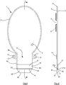
- the collecting bag shown in the drawings is designed as a reusable ostomy bag and comprises a bag member 1 and a discharge portion 8 having a discharge opening 9, through which the collecting bag may be emptied of its contents.
- the general principles relating to such an ostomy bag are well known and common.
- One example of an ostomy bag is, for instance, disclosed in Applicant's international published application No. WO 2004/030584 .
- a closure device is provided in the discharge portion 8.
- the fundamental principle underlying the closure mechanism in this kind of collecting bag kind is that two plate members are brought into contact with each other in an initial folding operation of the discharge portion 8 in its longitudinal direction. This will be described in further detail below.
- a first plate member 21 is provided on the first film blank 2, such that a distal edge 21b of the first plate member 21 is positioned near or at the distal end edge 2b of the first film blank 2.
- a second plate member 22 is provided on the extension 3e of the second film blank 3 such that a proximal edge 22a is positioned opposite the distal edge 21b of the first plate member 21 such that the proximal edge 22a and the distal edge 21b face each other.
- the first plate member 21 is positioned on the front side of the discharge portion 8, i.e. on the outer side of the first film blank 2
- the second plate member 22 is positioned on the front side of the discharge portion 8 as well, i.e. on the inner side of the extension 3e.
- the discharge opening 9 is provided as a slit-shaped opening between the two film blanks 2,3, namely as an opening between the extension 3e of the second film blank 3 and the distal end edge 2b of film blank 2.
- the discharge opening 9 is delimited in the longitudinal direction of the discharge portion 8 by the distal edge 21b of the first plate member 21 and thus extends between the distal edge 21b of the first plate member 21 and the proximal edge 22a of the second plate member 22, as the facing edges 21b, 22a are positioned on opposite sides of said discharge opening 9.
- the bag is brought from the open or discharge position, via the first position shown in Figs. 1 and 2 , via an intermediate closed position, a detail of the collecting bag being shown in a second and closed position Fig. 5 , to a position of use (not shown), in which the bag is closed and locked, by a number of folding operations and in a manner that will be described in further detail below.
- the discharge portion 8 is foldable and unfoldable by at least one folding in its longitudinal direction between the distal and proximal ends to bring the discharge portion from an open unfolded condition to a closed folded condition and vice versa.
- the collecting bag In the first position referred to in the above, and described in connection with Figs. 1 and 2 , the collecting bag is unfolded and the plate members are situated one after the other in the longitudinal direction of the discharge portion 8 and substantially parallel with each other. In this first position, the contents of the bag may in principle seep or flow out of the discharge opening.
- the plate members 21, 22 may be flexed slightly by applying opposite forces to the side edges 8c, 8d of the discharge portion 8 in the area of the plate members 21, 22 such that the side edges are moved towards each other in order to enlarge the opening area.
- the closed folded condition the first and second plate members 21, 22 are in contact with each other.
- the term "closed” is to be interpreted as meaning sealingly closed such that virtually no material (faeces) present in the collecting bag may travel from the inside of the bag to the outside. This closed condition is attained already when the discharge portion 8 has been folded once such that the plate members have been brought into contact with each other into the above-mentioned closed folded condition.
- Locked should be interpreted to describe a condition, in which there is no need for a user to keep the discharge portion 8 in its folded position manually. Consequently, the bag will have reached its closed condition before it reaches its locked condition.
- the discharge portion 8 When closing the bag, the discharge portion 8 is folded starting from the distal end by initially folding the second plate member 22 against the first plate member 21, using the distal edge 21b of the first plate member 21 as a pivot. Following this initial folding, the intermediate position, which represents a closed folded condition, shown in Fig. 5 is attained. This initial folding will have a slight stretching effect on the material of the second film blank 3. During this folding, and in the intermediate position as well as in the position of use, the strap members 23, 24 connected with the film blank 3 as well as to the plate members 21, 22 act as reinforcement of the film blank 3 An effectively sealed closure of the discharge opening 9 is thus provided.
- a locking device which in the embodiment shown comprises foldable locking strips 12 and 13 projecting from the side edges 8c and 8d of the discharge portion 8 at the proximal end 8a thereof.
- the projecting foldable locking strips 12 and 13, which may be formed integrally with one of or both the film blanks 2,3, are provided with a first set of locking means, for instance of the hook-and-loop type, which in the embodiment shown is constituted by hook elements 10,11, but which may also comprise snap fastening members, different types of adhesive members etc. and are releasably engageable with a second set of mating locking means provided on the outer side of the second film blank 3.
- a plate 14 of loop elements constitutes the second set of locking means.
- the locking device may be designed in other ways, e.g. as described in applicant's International application No. WO 99/25278 , or as a traditional locking clip.
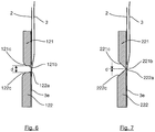
- the first and second plate members 21, 22 are positioned in such a way on the discharge portion 8 of the collecting bag that a small clearance defining a distance d, occurs between the edges facing each other, i.e. the proximal edge 22a of the second plate member 22 and the distal edge 21b of the first plate member 21.
- the distance d may be predetermined according to the materials and dimensions of, i.a., the film blanks and plate members, and corresponds to the height of the strap members 23, 24 in the longitudinal direction of the discharge portion.
- the predetermined distance d between the facing edges 21b, 22a should be smaller than the total sum ti + t 2 of the thickness ti of the first plate member 21 and the thickness t 2 of the second plate member 22.
- the distance d is in the range from 25-90%, preferably 28-70%, and most preferably 30-45%, of the total thickness ti + t 2 of the first plate member 21 and the second plate member 22.
- ti is approximately 0.7 mm and t 2 approximately 0,9 mm in the area adjacent the discharge opening 9. As the distance d is approximately 0.5 mm, this results in a ratio of approximately 31%.
- the thickness of the strap members 23, 24 is preferably chosen such that the thickness t of each strap member 23, 24 is substantially larger than the thickness of each film blank. Typical values of the thickness are 0.15-1 mm, whereas the thickness of the film blanks is approximately 75 ⁇ m (0.075 mm).
- the thickness of the strap members is also related to the thickness of the plate members and to the distance d between them in order to obtain a sealing closure of the discharge portion, it is preferable to choose the thickness t in the range 50-100%, preferably 75-85%, of the distance d between the distal edge 21b of the first plate member 21 and the proximal edge 22a of the second plate member 22. In the example corresponding to the embodiment shown, the thickness t is approximately 0.40 mm, thus resulting in a ratio of approximately 80%.
- the strap members 23, 24 are formed integrally with the plate members 21, 22 to form a single unit, but they may in principle be connected to the plate members 21, 22 in any suitable manner.
- the strap members may be formed as separate parts connected with the plate members, or as parts integral with only one of the plate members to be connected with the other plate member in any suitable manner.
- the strap members 23, 24 are connected with at least the second film blank 3, either in the same operation as the attachment of one or both of the plate members 21, 22 to the respective film blank, or in a separate operation.
- the strap members may also be made from another material than one or both of the plate members, either as co-moulded parts of another material, or as at least partly separate parts of another material, including for instance extended or folded-over portions of one or both of the film blanks of the discharge portion. It is also conceivable to form the strap members with a height, i.e. length in the longitudinal direction of the discharge portion, larger than the distance d between the facing edges to provide for an overlap of the strap members and one or both plate members. In the embodiment shown, the number of strap members is two, one at each side of the discharge opening. It is also possible to have more than one strap member in each side, e.g. two narrow strap members in a side-by-side relationship.
- the strap members serve to protect the film blanks during the joining operation.
- strap members integral with the plate member keep the plate members together during handling in the manufacturing process.
- the strap members serve to increase the strength of the hinge constituted by the film blank when folding the discharge portion.
- the distance d between the facing edges has a tendency to widen during use of the collecting bag, i.e. when a number of folding and unfolding operations have been carried out.
- the presence of the strap members makes it possible to maintain a substantially constant distance and hence secure sealing closure of the discharge portion even after a large number of folding operations.
- each plate member 21, 22 is provided with a chamfer 21c, 22c extending in the entire width of the respective plate member 21, 22.
- Each chamfer 21c, 22c extends in a part of the thickness direction of the first and second plate member 21, 22, the chamfers being situated such that the facing edges 21b, 22a are substantially perpendicular to the film blanks 2 and 3 at the connection of the plate members 21, 22 to the respective film blanks 2 and 3, whereas the outward facing edges are chamfered to form a substantially funnel-shaped cross-sectional configuration.
- the chamfer extends in a part of the facing edges in the range 30 to 70% of the thickness of the respective plate member in the area adjacent the discharge opening 9, here approximately 50%.
- the chamfer angle may vary as well, but is conveniently about 45 degrees.
Landscapes
- Health & Medical Sciences (AREA)
- Life Sciences & Earth Sciences (AREA)
- General Health & Medical Sciences (AREA)
- Orthopedic Medicine & Surgery (AREA)
- Engineering & Computer Science (AREA)
- Biomedical Technology (AREA)
- Heart & Thoracic Surgery (AREA)
- Nursing (AREA)
- Vascular Medicine (AREA)
- Animal Behavior & Ethology (AREA)
- Epidemiology (AREA)
- Public Health (AREA)
- Veterinary Medicine (AREA)
- Orthopedics, Nursing, And Contraception (AREA)
- Bag Frames (AREA)
- Refuse Receptacles (AREA)
- Sampling And Sample Adjustment (AREA)
Claims (15)
- Sammelbeutel für menschliche Ausscheidungen nach der Art umfassend ein Beutelglied (1), einen Austragabschnitt (8), der eine Austragöffnung (9) aufweist, und ein erstes Plattenglied (21; 121) mit einem distalen Rand (21b; 121b) und ein zweites Plattenglied (22; 122) mit einem proximalen Rand (22a; 122a), wobei sich die Austragöffnung (9) zwischen den Rändern (21b, 22a; 121b, 122a) erstreckt, wobei das Verschließen der Austragöffnung (9) durch Falten des Austragabschnitts (8) in einer Längsrichtung erfolgt, um das erste Plattenglied (21; 121) mit dem zweiten Plattenglied (22; 122) in Kontakt zu bringen,
wobei mindestens einer der Ränder (21b, 22a; 121b, 122a) der Plattenglieder (21, 22; 121, 122) mit einer Kehle oder Abfasung (21c, 22c; 121c, 122c) versehen ist,
wobei sich jede Kehle oder Abfasung (21c, 22c; 121c, 122c) in einen Teil der Dickerichtung des ersten und/oder des zweiten Plattenglieds (21, 22; 121, 122) erstreckt, und
dadurch gekennzeichnet, dass sich die Kehle oder Abfasung (21c, 22c; 121c, 122c) in einen Teil der sich gegenüberliegenden Ränder im Bereich von 30 bis 70% der Dicke des jeweiligen Plattenglieds in dem der Austragöffnung (9) benachbarten Bereich erstreckt. - Sammelbeutel nach Anspruch 1, wobei sich jede Kehle oder Abfasung (21c, 22c; 121c, 122c) in die gesamte Breite des ersten und/oder zweiten Plattenglieds (21, 22; 121, 122) erstreckt.
- Sammelbeutel nach Anspruch 1 oder 2, wobei der distale Rand (21b) des ersten Plattenglieds (21) und der proximale Rand (22a) des zweiten Plattenglieds (22) jeweils mit einer Abfasung von ungefähr 45 Grad versehen sind, die sich in die gesamte Breite des jeweiligen Plattenglieds und über ungefähr 50% der Dicke jedes Plattenglieds erstreckt.
- Sammelbeutel nach Anspruch 1 oder 2, wobei der distale Rand (121b) des ersten Plattenglieds (121) und der proximale Rand (122a) des zweiten Plattenglieds (122) jeweils mit einer Kehle (121c, 122c) versehen sind, die sich in die gesamte Breite des jeweiligen Plattenglieds und über ungefähr 50% der Dicke jedes Plattenglieds erstreckt.
- Sammelbeutel nach einem der vorhergehenden Ansprüche, wobei der Sammelbeutel eine erste Position hat, in der das erste und das zweite Plattenglied (21, 22) hintereinander in der Längsrichtung des Austragabschnitts (8) und im Wesentlichen parallel zueinander angeordnet sind, wobei der distale Rand (21b) in der Position dem proximalen Rand (22a) zugewandt ist und das erste und das zweite Plattenglied einen vorbestimmten Abstand (d) zwischen den sich zugewandten Rändern (21b, 22a) haben, wobei der Abstand (d) in der Position kleiner als die Gesamtdicke (t1+ t2) des ersten Plattenglieds (21) und des zweiten Plattenglieds (22) ist und wobei mindestens zwei Bandglieder (23, 24) zwischen den einander zugewandten Rändern vorgesehen sind, wobei sich die Bandglieder über den gesamten Abstand (d) erstrecken.
- Sammelbeutel nach Anspruch 5, wobei jedes Bandglied (23, 24) eine Höhe in der Längsrichtung des Austragabschnitts (8) hat, die dem Abstand (d) entspricht.
- Sammelbeutel nach Anspruch 5 oder 6, wobei der Abstand (d) im Bereich von 25 - 90% der Gesamtdicke (t1+ t2) des ersten Plattenglieds (21) und des zweiten Plattenglieds (22) liegt.
- Sammelbeutel nach Anspruch 7, wobei der Abstand (d) im Bereich von 28 - 70% der Gesamtdicke (t1+ t2) des ersten Plattenglieds (21) und des zweiten Plattenglieds (22) liegt.
- Sammelbeutel nach Anspruch 8, wobei der Abstand (d) im Bereich von 30 - 45% der Gesamtdicke (t1+ t2) des ersten Plattenglieds (21) und des zweiten Plattenglieds (22) liegt.
- Sammelbeutel nach einem der Ansprüche 5 bis 9, wobei eine Dicke (t) jedes Bandglieds (23, 24) im Bereich von 50 - 100%, vorzugsweise 75 - 85%, des Abstands (d) zwischen dem distalen Rand (21b) des ersten Plattenglieds (21) und dem proximalen Rand (22a) des zweiten Plattenglieds (22) liegt.
- Sammelbeutel nach einem der Ansprüche 5 bis 10, wobei die Dicke (t) jedes Bandglieds (23, 24) wesentlich größer als eine Dicke jeweils eines ersten Folienzuschnitts (2) und eines zweiten Folienzuschnitts (3) ist, die das Beutelglied (1) und den Austragabschnitt (8) bilden.
- Sammelbeutel nach einem der Ansprüche 5 bis 11, wobei die Dicke (t) jedes Bandglieds (23, 24) im Bereich von 0,15 - 1 mm liegt.
- Sammelbeutel nach einem der Ansprüche 5 bis 12, wobei die Bandglieder (23, 24) integral mit den Plattengliedern (21, 22) ausgebildet sind, wobei die Bandglieder und die Plattenglieder eine Einheit bilden.
- Sammelbeutel nach Anspruch 13, wobei die integrierten Bandglieder (23, 24) und Plattenglieder (21, 22) als eine geformte Einheit vorgesehen sind.
- Sammelbeutel nach einem der Ansprüche 13 oder 14, wobei die integrierten Bandglieder (23, 24) und Plattenglieder (21, 22) aus Polyethylen (PE), Polypropylen (PP), einem Copolymer aus PE und Ethylenvinylacetat (EVA), Nylon oder einem beliebigen anderen geeigneten Material oder einer Kombination aus beliebigen derartigen Materialien gebildet sind.
Applications Claiming Priority (3)
| Application Number | Priority Date | Filing Date | Title |
|---|---|---|---|
| DKPA200600524 | 2006-04-11 | ||
| PCT/DK2007/050040 WO2007115574A1 (en) | 2006-04-11 | 2007-04-04 | A collecting bag having closure provided with a chamfer |
| EP07722695.9A EP2007330B1 (de) | 2006-04-11 | 2007-04-04 | Sammelbehälter aufweisend eine mit einer abschrägung versehene verschlussvorrichtung |
Related Parent Applications (2)
| Application Number | Title | Priority Date | Filing Date |
|---|---|---|---|
| EP07722695.9A Division EP2007330B1 (de) | 2006-04-11 | 2007-04-04 | Sammelbehälter aufweisend eine mit einer abschrägung versehene verschlussvorrichtung |
| EP07722695.9A Division-Into EP2007330B1 (de) | 2006-04-11 | 2007-04-04 | Sammelbehälter aufweisend eine mit einer abschrägung versehene verschlussvorrichtung |
Publications (2)
| Publication Number | Publication Date |
|---|---|
| EP3199130A1 EP3199130A1 (de) | 2017-08-02 |
| EP3199130B1 true EP3199130B1 (de) | 2019-01-09 |
Family
ID=37697901
Family Applications (2)
| Application Number | Title | Priority Date | Filing Date |
|---|---|---|---|
| EP17151705.5A Active EP3199130B1 (de) | 2006-04-11 | 2007-04-04 | Sammelbehälter aufweisend eine mit einer abschrägung versehene verschlussvorrichtung |
| EP07722695.9A Active EP2007330B1 (de) | 2006-04-11 | 2007-04-04 | Sammelbehälter aufweisend eine mit einer abschrägung versehene verschlussvorrichtung |
Family Applications After (1)
| Application Number | Title | Priority Date | Filing Date |
|---|---|---|---|
| EP07722695.9A Active EP2007330B1 (de) | 2006-04-11 | 2007-04-04 | Sammelbehälter aufweisend eine mit einer abschrägung versehene verschlussvorrichtung |
Country Status (12)
| Country | Link |
|---|---|
| US (1) | US8377019B2 (de) |
| EP (2) | EP3199130B1 (de) |
| JP (1) | JP5357006B2 (de) |
| CN (1) | CN101466331B (de) |
| AU (1) | AU2007236403B2 (de) |
| BR (1) | BRPI0710128B8 (de) |
| CA (1) | CA2648312C (de) |
| DK (2) | DK3199130T3 (de) |
| ES (2) | ES2639106T3 (de) |
| HU (2) | HUE042834T2 (de) |
| RU (1) | RU2008144411A (de) |
| WO (1) | WO2007115574A1 (de) |
Families Citing this family (23)
| Publication number | Priority date | Publication date | Assignee | Title |
|---|---|---|---|---|
| EP2229924A1 (de) | 2009-03-17 | 2010-09-22 | Hollister Incorporated | Entwässerbarer Ostomiebeutel |
| DE102010010558B3 (de) * | 2010-03-05 | 2011-06-30 | Pricelius, Günter, 78464 | Stomabeutelsystem |
| US8672907B2 (en) | 2010-07-26 | 2014-03-18 | Hollister Incorporated | Drainable ostomy pouch |
| EP2510910A1 (de) * | 2011-04-12 | 2012-10-17 | Hollister Incorporated | Ostomiebeutel |
| EP3169284B1 (de) * | 2014-07-16 | 2018-10-17 | Coloplast A/S | Entleerbarer sammelbeutel |
| HUE063257T2 (hu) | 2015-10-14 | 2024-01-28 | Convatec Technologies Inc | Nyitórendszerrel rendelkezõ orvostechnikai eszköz |
| CA3049266A1 (en) * | 2017-01-20 | 2018-07-26 | Hollister Incorporated | Drainable ostomy pouch |
| GB2566725B (en) * | 2017-09-22 | 2022-02-23 | Salts Healthcare Ltd | A drainable ostomy appliance |
| GB2566723B (en) * | 2017-09-22 | 2022-02-23 | Salts Healthcare Ltd | A drainable ostomy appliance |
| GB2566721B (en) * | 2017-09-22 | 2020-07-15 | Salts Healthcare Ltd | An ostomy appliance |
| GB2566724B (en) * | 2017-09-22 | 2022-02-23 | Salts Healthcare Ltd | A drainable ostomy appliance |
| GB201715388D0 (en) * | 2017-09-22 | 2017-11-08 | Salts Healthcare Ltd | An ostomy appliance |
| GB2566722B (en) * | 2017-09-22 | 2022-02-23 | Salts Healthcare Ltd | A drainable ostomy appliance |
| GB2566719B (en) * | 2017-09-22 | 2022-03-16 | Salts Healthcare Ltd | A drainable ostomy appliance |
| MX2020004744A (es) | 2017-11-09 | 2020-08-13 | 11 Health And Tech Limited | Sistema y metodo de monitoreo de ostomia. |
| USD893514S1 (en) | 2018-11-08 | 2020-08-18 | 11 Health And Technologies Limited | Display screen or portion thereof with graphical user interface |
| EP3962422B1 (de) | 2019-05-03 | 2023-08-02 | Hollister Incorporated | Verfahren zur herstellung eines entleerbarer stomabeutel |
| CN111419520B (zh) * | 2020-03-31 | 2022-02-11 | 中国人民解放军陆军特色医学中心 | 一种单手操作的便捷式造口装置 |
| EP4364777B1 (de) | 2020-08-03 | 2026-05-06 | C. R. Bard, Inc. | Intermittierende katheteranordnungen und verfahren dafür |
| US12611519B2 (en) | 2020-09-11 | 2026-04-28 | C. R. Bard, Inc. | Intermittent-catheter assembly and methods thereof |
| AU2021361238A1 (en) | 2020-10-15 | 2023-05-25 | Convatec Technologies Inc. | Ostomy systems and methods |
| EP4404880A1 (de) * | 2021-09-29 | 2024-07-31 | C. R. Bard, Inc. | Harnkathetersystem |
| DK4284311T3 (da) * | 2021-12-29 | 2024-07-08 | Hollister Inc | Stomiposelukkesystem |
Family Cites Families (10)
| Publication number | Priority date | Publication date | Assignee | Title |
|---|---|---|---|---|
| US3268106A (en) * | 1964-01-20 | 1966-08-23 | Satz William | Resealable container closure |
| EP1033951B1 (de) | 1997-11-19 | 2004-03-10 | Coloplast A/S | Sammelbeutel für menschliche ausscheidungen |
| DK173411B2 (da) * | 1998-06-19 | 2007-04-16 | Coloplast As | Opsamlingspose til menneskelige legemssekreter |
| US6045542A (en) | 1999-01-13 | 2000-04-04 | Cawood Family Limited Partnership | Urine collection device |
| WO2001028470A1 (en) | 1999-10-20 | 2001-04-26 | Coloplast A/S | A drainable collection bag for human body wastes |
| JP2001139039A (ja) * | 1999-11-17 | 2001-05-22 | Kao Corp | 包装袋 |
| JP4604415B2 (ja) | 2001-07-19 | 2011-01-05 | パナソニック株式会社 | スピーカ |
| US20040129589A1 (en) * | 2002-01-10 | 2004-07-08 | Tucker Matthew W. | Shipping container and support dunnage |
| FR2839883B1 (fr) * | 2002-05-21 | 2005-02-25 | Braun Medical | Poche de recueil de fluides corporels munie d'un dispositif d'ouverture et de fermeture d'un canal d'evacuation |
| DK176289B1 (da) * | 2002-10-02 | 2007-06-11 | Coloplast As | Opsamlingspose med forbedret lukke |
-
2007
- 2007-04-04 ES ES07722695.9T patent/ES2639106T3/es active Active
- 2007-04-04 EP EP17151705.5A patent/EP3199130B1/de active Active
- 2007-04-04 WO PCT/DK2007/050040 patent/WO2007115574A1/en not_active Ceased
- 2007-04-04 DK DK17151705.5T patent/DK3199130T3/en active
- 2007-04-04 RU RU2008144411/14A patent/RU2008144411A/ru not_active Application Discontinuation
- 2007-04-04 EP EP07722695.9A patent/EP2007330B1/de active Active
- 2007-04-04 HU HUE17151705A patent/HUE042834T2/hu unknown
- 2007-04-04 BR BRPI0710128A patent/BRPI0710128B8/pt not_active IP Right Cessation
- 2007-04-04 ES ES17151705T patent/ES2718073T3/es active Active
- 2007-04-04 JP JP2009504567A patent/JP5357006B2/ja not_active Expired - Fee Related
- 2007-04-04 HU HUE07722695A patent/HUE036307T2/hu unknown
- 2007-04-04 DK DK07722695.9T patent/DK2007330T3/en active
- 2007-04-04 US US12/226,132 patent/US8377019B2/en active Active
- 2007-04-04 CA CA2648312A patent/CA2648312C/en active Active
- 2007-04-04 CN CN2007800215590A patent/CN101466331B/zh active Active
- 2007-04-04 AU AU2007236403A patent/AU2007236403B2/en not_active Ceased
Non-Patent Citations (1)
| Title |
|---|
| None * |
Also Published As
| Publication number | Publication date |
|---|---|
| AU2007236403B2 (en) | 2010-10-07 |
| AU2007236403A1 (en) | 2007-10-18 |
| WO2007115574A1 (en) | 2007-10-18 |
| HUE042834T2 (hu) | 2019-07-29 |
| DK3199130T3 (en) | 2019-04-23 |
| BRPI0710128B8 (pt) | 2021-06-22 |
| CN101466331B (zh) | 2011-06-08 |
| EP2007330B1 (de) | 2017-06-21 |
| RU2008144411A (ru) | 2010-05-20 |
| EP3199130A1 (de) | 2017-08-02 |
| CA2648312A1 (en) | 2007-10-18 |
| BRPI0710128A2 (pt) | 2012-10-09 |
| JP5357006B2 (ja) | 2013-12-04 |
| CA2648312C (en) | 2014-11-04 |
| US8377019B2 (en) | 2013-02-19 |
| BRPI0710128B1 (pt) | 2018-06-19 |
| CN101466331A (zh) | 2009-06-24 |
| US20090192479A1 (en) | 2009-07-30 |
| HUE036307T2 (hu) | 2018-06-28 |
| DK2007330T3 (en) | 2017-10-09 |
| ES2639106T3 (es) | 2017-10-25 |
| EP2007330A1 (de) | 2008-12-31 |
| JP2009533102A (ja) | 2009-09-17 |
| ES2718073T3 (es) | 2019-06-27 |
Similar Documents
| Publication | Publication Date | Title |
|---|---|---|
| EP3199130B1 (de) | Sammelbehälter aufweisend eine mit einer abschrägung versehene verschlussvorrichtung | |
| EP2007331B1 (de) | Sammelbehälter mit verbessertem verschluss und verfahren zur herstellung dieses sammelbehälters | |
| US7223260B2 (en) | Collecting bag having an improved closure | |
| EP4284311B1 (de) | Stomabeutel-verschlusssystem |
Legal Events
| Date | Code | Title | Description |
|---|---|---|---|
| PUAI | Public reference made under article 153(3) epc to a published international application that has entered the european phase |
Free format text: ORIGINAL CODE: 0009012 |
|
| STAA | Information on the status of an ep patent application or granted ep patent |
Free format text: STATUS: THE APPLICATION HAS BEEN PUBLISHED |
|
| AC | Divisional application: reference to earlier application |
Ref document number: 2007330 Country of ref document: EP Kind code of ref document: P |
|
| AK | Designated contracting states |
Kind code of ref document: A1 Designated state(s): AT BE BG CH CY CZ DE DK EE ES FI FR GB GR HU IE IS IT LI LT LU LV MC MT NL PL PT RO SE SI SK TR |
|
| STAA | Information on the status of an ep patent application or granted ep patent |
Free format text: STATUS: REQUEST FOR EXAMINATION WAS MADE |
|
| 17P | Request for examination filed |
Effective date: 20180202 |
|
| RBV | Designated contracting states (corrected) |
Designated state(s): AT BE BG CH CY CZ DE DK EE ES FI FR GB GR HU IE IS IT LI LT LU LV MC MT NL PL PT RO SE SI SK TR |
|
| GRAP | Despatch of communication of intention to grant a patent |
Free format text: ORIGINAL CODE: EPIDOSNIGR1 |
|
| STAA | Information on the status of an ep patent application or granted ep patent |
Free format text: STATUS: GRANT OF PATENT IS INTENDED |
|
| INTG | Intention to grant announced |
Effective date: 20180817 |
|
| GRAS | Grant fee paid |
Free format text: ORIGINAL CODE: EPIDOSNIGR3 |
|
| GRAA | (expected) grant |
Free format text: ORIGINAL CODE: 0009210 |
|
| STAA | Information on the status of an ep patent application or granted ep patent |
Free format text: STATUS: THE PATENT HAS BEEN GRANTED |
|
| AC | Divisional application: reference to earlier application |
Ref document number: 2007330 Country of ref document: EP Kind code of ref document: P |
|
| AK | Designated contracting states |
Kind code of ref document: B1 Designated state(s): AT BE BG CH CY CZ DE DK EE ES FI FR GB GR HU IE IS IT LI LT LU LV MC MT NL PL PT RO SE SI SK TR |
|
| REG | Reference to a national code |
Ref country code: GB Ref legal event code: FG4D |
|
| REG | Reference to a national code |
Ref country code: CH Ref legal event code: EP Ref country code: AT Ref legal event code: REF Ref document number: 1086402 Country of ref document: AT Kind code of ref document: T Effective date: 20190115 |
|
| REG | Reference to a national code |
Ref country code: IE Ref legal event code: FG4D |
|
| REG | Reference to a national code |
Ref country code: DE Ref legal event code: R096 Ref document number: 602007057416 Country of ref document: DE |
|
| REG | Reference to a national code |
Ref country code: DK Ref legal event code: T3 Effective date: 20190415 Ref country code: SE Ref legal event code: TRGR |
|
| REG | Reference to a national code |
Ref country code: NL Ref legal event code: FP |
|
| REG | Reference to a national code |
Ref country code: LT Ref legal event code: MG4D |
|
| REG | Reference to a national code |
Ref country code: ES Ref legal event code: FG2A Ref document number: 2718073 Country of ref document: ES Kind code of ref document: T3 Effective date: 20190627 |
|
| REG | Reference to a national code |
Ref country code: AT Ref legal event code: MK05 Ref document number: 1086402 Country of ref document: AT Kind code of ref document: T Effective date: 20190109 |
|
| REG | Reference to a national code |
Ref country code: HU Ref legal event code: AG4A Ref document number: E042834 Country of ref document: HU |
|
| PG25 | Lapsed in a contracting state [announced via postgrant information from national office to epo] |
Ref country code: FI Free format text: LAPSE BECAUSE OF FAILURE TO SUBMIT A TRANSLATION OF THE DESCRIPTION OR TO PAY THE FEE WITHIN THE PRESCRIBED TIME-LIMIT Effective date: 20190109 Ref country code: PL Free format text: LAPSE BECAUSE OF FAILURE TO SUBMIT A TRANSLATION OF THE DESCRIPTION OR TO PAY THE FEE WITHIN THE PRESCRIBED TIME-LIMIT Effective date: 20190109 Ref country code: PT Free format text: LAPSE BECAUSE OF FAILURE TO SUBMIT A TRANSLATION OF THE DESCRIPTION OR TO PAY THE FEE WITHIN THE PRESCRIBED TIME-LIMIT Effective date: 20190509 Ref country code: LT Free format text: LAPSE BECAUSE OF FAILURE TO SUBMIT A TRANSLATION OF THE DESCRIPTION OR TO PAY THE FEE WITHIN THE PRESCRIBED TIME-LIMIT Effective date: 20190109 |
|
| PG25 | Lapsed in a contracting state [announced via postgrant information from national office to epo] |
Ref country code: GR Free format text: LAPSE BECAUSE OF FAILURE TO SUBMIT A TRANSLATION OF THE DESCRIPTION OR TO PAY THE FEE WITHIN THE PRESCRIBED TIME-LIMIT Effective date: 20190410 Ref country code: BG Free format text: LAPSE BECAUSE OF FAILURE TO SUBMIT A TRANSLATION OF THE DESCRIPTION OR TO PAY THE FEE WITHIN THE PRESCRIBED TIME-LIMIT Effective date: 20190409 Ref country code: IS Free format text: LAPSE BECAUSE OF FAILURE TO SUBMIT A TRANSLATION OF THE DESCRIPTION OR TO PAY THE FEE WITHIN THE PRESCRIBED TIME-LIMIT Effective date: 20190509 Ref country code: LV Free format text: LAPSE BECAUSE OF FAILURE TO SUBMIT A TRANSLATION OF THE DESCRIPTION OR TO PAY THE FEE WITHIN THE PRESCRIBED TIME-LIMIT Effective date: 20190109 |
|
| REG | Reference to a national code |
Ref country code: DE Ref legal event code: R097 Ref document number: 602007057416 Country of ref document: DE |
|
| PG25 | Lapsed in a contracting state [announced via postgrant information from national office to epo] |
Ref country code: EE Free format text: LAPSE BECAUSE OF FAILURE TO SUBMIT A TRANSLATION OF THE DESCRIPTION OR TO PAY THE FEE WITHIN THE PRESCRIBED TIME-LIMIT Effective date: 20190109 Ref country code: AT Free format text: LAPSE BECAUSE OF FAILURE TO SUBMIT A TRANSLATION OF THE DESCRIPTION OR TO PAY THE FEE WITHIN THE PRESCRIBED TIME-LIMIT Effective date: 20190109 Ref country code: SK Free format text: LAPSE BECAUSE OF FAILURE TO SUBMIT A TRANSLATION OF THE DESCRIPTION OR TO PAY THE FEE WITHIN THE PRESCRIBED TIME-LIMIT Effective date: 20190109 Ref country code: CZ Free format text: LAPSE BECAUSE OF FAILURE TO SUBMIT A TRANSLATION OF THE DESCRIPTION OR TO PAY THE FEE WITHIN THE PRESCRIBED TIME-LIMIT Effective date: 20190109 Ref country code: RO Free format text: LAPSE BECAUSE OF FAILURE TO SUBMIT A TRANSLATION OF THE DESCRIPTION OR TO PAY THE FEE WITHIN THE PRESCRIBED TIME-LIMIT Effective date: 20190109 |
|
| PLBE | No opposition filed within time limit |
Free format text: ORIGINAL CODE: 0009261 |
|
| STAA | Information on the status of an ep patent application or granted ep patent |
Free format text: STATUS: NO OPPOSITION FILED WITHIN TIME LIMIT |
|
| REG | Reference to a national code |
Ref country code: CH Ref legal event code: PL |
|
| 26N | No opposition filed |
Effective date: 20191010 |
|
| REG | Reference to a national code |
Ref country code: BE Ref legal event code: MM Effective date: 20190430 |
|
| PG25 | Lapsed in a contracting state [announced via postgrant information from national office to epo] |
Ref country code: MC Free format text: LAPSE BECAUSE OF FAILURE TO SUBMIT A TRANSLATION OF THE DESCRIPTION OR TO PAY THE FEE WITHIN THE PRESCRIBED TIME-LIMIT Effective date: 20190109 Ref country code: LU Free format text: LAPSE BECAUSE OF NON-PAYMENT OF DUE FEES Effective date: 20190404 |
|
| PG25 | Lapsed in a contracting state [announced via postgrant information from national office to epo] |
Ref country code: LI Free format text: LAPSE BECAUSE OF NON-PAYMENT OF DUE FEES Effective date: 20190430 Ref country code: CH Free format text: LAPSE BECAUSE OF NON-PAYMENT OF DUE FEES Effective date: 20190430 |
|
| PG25 | Lapsed in a contracting state [announced via postgrant information from national office to epo] |
Ref country code: BE Free format text: LAPSE BECAUSE OF NON-PAYMENT OF DUE FEES Effective date: 20190430 Ref country code: SI Free format text: LAPSE BECAUSE OF FAILURE TO SUBMIT A TRANSLATION OF THE DESCRIPTION OR TO PAY THE FEE WITHIN THE PRESCRIBED TIME-LIMIT Effective date: 20190109 |
|
| PG25 | Lapsed in a contracting state [announced via postgrant information from national office to epo] |
Ref country code: TR Free format text: LAPSE BECAUSE OF FAILURE TO SUBMIT A TRANSLATION OF THE DESCRIPTION OR TO PAY THE FEE WITHIN THE PRESCRIBED TIME-LIMIT Effective date: 20190109 |
|
| PG25 | Lapsed in a contracting state [announced via postgrant information from national office to epo] |
Ref country code: CY Free format text: LAPSE BECAUSE OF FAILURE TO SUBMIT A TRANSLATION OF THE DESCRIPTION OR TO PAY THE FEE WITHIN THE PRESCRIBED TIME-LIMIT Effective date: 20190109 |
|
| PG25 | Lapsed in a contracting state [announced via postgrant information from national office to epo] |
Ref country code: MT Free format text: LAPSE BECAUSE OF FAILURE TO SUBMIT A TRANSLATION OF THE DESCRIPTION OR TO PAY THE FEE WITHIN THE PRESCRIBED TIME-LIMIT Effective date: 20190109 |
|
| PGFP | Annual fee paid to national office [announced via postgrant information from national office to epo] |
Ref country code: NL Payment date: 20230426 Year of fee payment: 17 |
|
| PGFP | Annual fee paid to national office [announced via postgrant information from national office to epo] |
Ref country code: IT Payment date: 20230419 Year of fee payment: 17 Ref country code: ES Payment date: 20230503 Year of fee payment: 17 |
|
| PGFP | Annual fee paid to national office [announced via postgrant information from national office to epo] |
Ref country code: SE Payment date: 20230427 Year of fee payment: 17 Ref country code: HU Payment date: 20230331 Year of fee payment: 17 |
|
| REG | Reference to a national code |
Ref country code: SE Ref legal event code: EUG |
|
| REG | Reference to a national code |
Ref country code: NL Ref legal event code: MM Effective date: 20240501 |
|
| PG25 | Lapsed in a contracting state [announced via postgrant information from national office to epo] |
Ref country code: HU Free format text: LAPSE BECAUSE OF NON-PAYMENT OF DUE FEES Effective date: 20240405 |
|
| PG25 | Lapsed in a contracting state [announced via postgrant information from national office to epo] |
Ref country code: NL Free format text: LAPSE BECAUSE OF NON-PAYMENT OF DUE FEES Effective date: 20240501 |
|
| PG25 | Lapsed in a contracting state [announced via postgrant information from national office to epo] |
Ref country code: NL Free format text: LAPSE BECAUSE OF NON-PAYMENT OF DUE FEES Effective date: 20240501 Ref country code: HU Free format text: LAPSE BECAUSE OF NON-PAYMENT OF DUE FEES Effective date: 20240405 |
|
| PG25 | Lapsed in a contracting state [announced via postgrant information from national office to epo] |
Ref country code: IT Free format text: LAPSE BECAUSE OF NON-PAYMENT OF DUE FEES Effective date: 20240404 |
|
| REG | Reference to a national code |
Ref country code: ES Ref legal event code: FD2A Effective date: 20250527 |
|
| PGFP | Annual fee paid to national office [announced via postgrant information from national office to epo] |
Ref country code: DE Payment date: 20250429 Year of fee payment: 19 |
|
| PG25 | Lapsed in a contracting state [announced via postgrant information from national office to epo] |
Ref country code: ES Free format text: LAPSE BECAUSE OF NON-PAYMENT OF DUE FEES Effective date: 20240405 |
|
| PGFP | Annual fee paid to national office [announced via postgrant information from national office to epo] |
Ref country code: GB Payment date: 20250428 Year of fee payment: 19 Ref country code: DK Payment date: 20250425 Year of fee payment: 19 |
|
| PGFP | Annual fee paid to national office [announced via postgrant information from national office to epo] |
Ref country code: FR Payment date: 20250425 Year of fee payment: 19 |
|
| PGFP | Annual fee paid to national office [announced via postgrant information from national office to epo] |
Ref country code: IE Payment date: 20250428 Year of fee payment: 19 |
|
| PG25 | Lapsed in a contracting state [announced via postgrant information from national office to epo] |
Ref country code: SE Free format text: LAPSE BECAUSE OF NON-PAYMENT OF DUE FEES Effective date: 20240405 |