EP3198876B1 - Generation and encoding of residual integral images - Google Patents
Generation and encoding of residual integral images Download PDFInfo
- Publication number
- EP3198876B1 EP3198876B1 EP15778371.3A EP15778371A EP3198876B1 EP 3198876 B1 EP3198876 B1 EP 3198876B1 EP 15778371 A EP15778371 A EP 15778371A EP 3198876 B1 EP3198876 B1 EP 3198876B1
- Authority
- EP
- European Patent Office
- Prior art keywords
- image
- integral image
- view
- coding
- decoding
- Prior art date
- Legal status (The legal status is an assumption and is not a legal conclusion. Google has not performed a legal analysis and makes no representation as to the accuracy of the status listed.)
- Active
Links
- 238000000034 method Methods 0.000 claims description 62
- 238000000354 decomposition reaction Methods 0.000 claims description 19
- 238000012545 processing Methods 0.000 claims description 19
- 238000011002 quantification Methods 0.000 claims description 16
- 238000004364 calculation method Methods 0.000 claims description 15
- 238000004590 computer program Methods 0.000 claims description 9
- 238000012986 modification Methods 0.000 claims description 7
- 230000004048 modification Effects 0.000 claims description 7
- 238000004458 analytical method Methods 0.000 claims description 4
- 238000010276 construction Methods 0.000 claims 2
- 230000009466 transformation Effects 0.000 description 67
- 238000013139 quantization Methods 0.000 description 36
- 230000003044 adaptive effect Effects 0.000 description 10
- 101100536354 Drosophila melanogaster tant gene Proteins 0.000 description 9
- 241001080024 Telles Species 0.000 description 9
- 239000003086 colorant Substances 0.000 description 6
- 230000006835 compression Effects 0.000 description 5
- 238000007906 compression Methods 0.000 description 5
- 229940082150 encore Drugs 0.000 description 5
- 101100382340 Arabidopsis thaliana CAM2 gene Proteins 0.000 description 4
- 101100494530 Brassica oleracea var. botrytis CAL-A gene Proteins 0.000 description 4
- 101100165913 Brassica oleracea var. italica CAL gene Proteins 0.000 description 4
- 101150118283 CAL1 gene Proteins 0.000 description 4
- 101100029577 Saccharomyces cerevisiae (strain ATCC 204508 / S288c) CDC43 gene Proteins 0.000 description 4
- 101100439683 Saccharomyces cerevisiae (strain ATCC 204508 / S288c) CHS3 gene Proteins 0.000 description 4
- 101150014174 calm gene Proteins 0.000 description 4
- 238000006073 displacement reaction Methods 0.000 description 4
- 238000009499 grossing Methods 0.000 description 4
- 238000000638 solvent extraction Methods 0.000 description 4
- 230000001131 transforming effect Effects 0.000 description 4
- 230000008901 benefit Effects 0.000 description 3
- 238000004422 calculation algorithm Methods 0.000 description 3
- 238000011161 development Methods 0.000 description 3
- 238000003384 imaging method Methods 0.000 description 3
- 230000011664 signaling Effects 0.000 description 3
- 238000012360 testing method Methods 0.000 description 3
- 102100021849 Calretinin Human genes 0.000 description 2
- 208000037170 Delayed Emergence from Anesthesia Diseases 0.000 description 2
- 101000898072 Homo sapiens Calretinin Proteins 0.000 description 2
- 238000004891 communication Methods 0.000 description 2
- 230000003628 erosive effect Effects 0.000 description 2
- 230000003287 optical effect Effects 0.000 description 2
- 230000009467 reduction Effects 0.000 description 2
- 101100006352 Saccharomyces cerevisiae (strain ATCC 204508 / S288c) CHS5 gene Proteins 0.000 description 1
- 238000005516 engineering process Methods 0.000 description 1
- 238000001914 filtration Methods 0.000 description 1
- 238000003706 image smoothing Methods 0.000 description 1
- 239000011159 matrix material Substances 0.000 description 1
- 238000004377 microelectronic Methods 0.000 description 1
- 238000005192 partition Methods 0.000 description 1
- 230000008707 rearrangement Effects 0.000 description 1
- 238000000844 transformation Methods 0.000 description 1
- 238000012800 visualization Methods 0.000 description 1
Images


Classifications
-
- H—ELECTRICITY
- H04—ELECTRIC COMMUNICATION TECHNIQUE
- H04N—PICTORIAL COMMUNICATION, e.g. TELEVISION
- H04N19/00—Methods or arrangements for coding, decoding, compressing or decompressing digital video signals
- H04N19/10—Methods or arrangements for coding, decoding, compressing or decompressing digital video signals using adaptive coding
- H04N19/102—Methods or arrangements for coding, decoding, compressing or decompressing digital video signals using adaptive coding characterised by the element, parameter or selection affected or controlled by the adaptive coding
- H04N19/124—Quantisation
-
- H—ELECTRICITY
- H04—ELECTRIC COMMUNICATION TECHNIQUE
- H04N—PICTORIAL COMMUNICATION, e.g. TELEVISION
- H04N19/00—Methods or arrangements for coding, decoding, compressing or decompressing digital video signals
- H04N19/10—Methods or arrangements for coding, decoding, compressing or decompressing digital video signals using adaptive coding
- H04N19/134—Methods or arrangements for coding, decoding, compressing or decompressing digital video signals using adaptive coding characterised by the element, parameter or criterion affecting or controlling the adaptive coding
- H04N19/146—Data rate or code amount at the encoder output
- H04N19/147—Data rate or code amount at the encoder output according to rate distortion criteria
-
- H—ELECTRICITY
- H04—ELECTRIC COMMUNICATION TECHNIQUE
- H04N—PICTORIAL COMMUNICATION, e.g. TELEVISION
- H04N19/00—Methods or arrangements for coding, decoding, compressing or decompressing digital video signals
- H04N19/10—Methods or arrangements for coding, decoding, compressing or decompressing digital video signals using adaptive coding
- H04N19/169—Methods or arrangements for coding, decoding, compressing or decompressing digital video signals using adaptive coding characterised by the coding unit, i.e. the structural portion or semantic portion of the video signal being the object or the subject of the adaptive coding
- H04N19/17—Methods or arrangements for coding, decoding, compressing or decompressing digital video signals using adaptive coding characterised by the coding unit, i.e. the structural portion or semantic portion of the video signal being the object or the subject of the adaptive coding the unit being an image region, e.g. an object
- H04N19/172—Methods or arrangements for coding, decoding, compressing or decompressing digital video signals using adaptive coding characterised by the coding unit, i.e. the structural portion or semantic portion of the video signal being the object or the subject of the adaptive coding the unit being an image region, e.g. an object the region being a picture, frame or field
-
- H—ELECTRICITY
- H04—ELECTRIC COMMUNICATION TECHNIQUE
- H04N—PICTORIAL COMMUNICATION, e.g. TELEVISION
- H04N19/00—Methods or arrangements for coding, decoding, compressing or decompressing digital video signals
- H04N19/50—Methods or arrangements for coding, decoding, compressing or decompressing digital video signals using predictive coding
- H04N19/597—Methods or arrangements for coding, decoding, compressing or decompressing digital video signals using predictive coding specially adapted for multi-view video sequence encoding
Definitions
- the present invention relates generally to the field of image processing, and more specifically to the encoding and decoding of integral images and integral image sequences.
- the invention may especially, but not exclusively, apply to video coding implemented in current AVC and HEVC video encoders and their extensions (MVC, 3D-AVC, MV-HEVC, 3D-HEVC, etc.), and to corresponding video decoding.
- Integral imaging is a technique of representing relief images. It is considered particularly promising in the development of 3D television, especially because it offers, not a stereoscopic visualization of images, but a total parallax.
- An integral image is conventionally composed of different elementary images also called micro-images that each represent different perspectives of a three-dimensional scene.
- An integral image is acquired using an image capture device that includes a camera and a lenticular array that is disposed between the three-dimensional scene and the camera.
- the first method of coding is to apply two-dimensional (2D) coding to the integral image as such.
- 2D two-dimensional
- the characteristics of a conventional 2D codec are modified to adapt to the particular structure of the integral images.
- DWT discrete wavelet transform
- the second coding method consists in breaking down the integral image into a plurality of views, each of which represents a 3D scene in a specific viewing angular position. Each pixel or zone of pixels associated with a considered view records the information relating to the light rays reflected by an object in perspective in the scene, in the same direction. 3D coding is then applied to the resulting views. For example, in documents 3D Holoscopic video coding using MVC, Dick, Almeida, Soares, Nunes, EUROCON 2011 and "Efficient compression method for integral images using multi-view video coding", S. Shi, P. Gioia, and G.
- a series of views of an integral image may be considered as a multi-view image of the scene and thereby a sequence of integral images may be decomposed into a multi-view video sequence.
- said series of views can be compressed using a standard encoding technique such as MVC (Multi-view coding).
- a disadvantage of this second coding method is that its practical application imposes a limitation of the number of views to be coded by the MVC coding technique.
- a high resolution for the views or a large number of views is necessary because these views must contain all the angular information contained in the integral image which is subsequently reconstructed at decoder.
- a third method of coding is described in the following document: CHEOL-HWA YOO AND AL: "Enhanced compression of integral images by combined residual images and MPEG-4 algorithm in three-dimensional integral imaging", OPTICS COMMUNICATIONS, NORTH-HOLLAND PUBLISHING CO. AMSTERDAM, NL, vol. 284, no. 20, June 13, 2011, pages 4884-4893, ISSN: 0030-4018, DOI: 10.1016 / J.OPTCOM.2011.06.020 .
- One of the aims of the invention is to overcome disadvantages of the state of the art mentioned above.
- the coding of an integral image according to the invention is therefore much less expensive in the number of data to be encoded than the coding methods of the prior art described above.
- the recomposition of an integral image requires the knowledge of at least one image capture parameter associated with the image capture device, such as, for example, the resolution of the micro-images constituting the image. integral image as well as the number of these micro-images.
- the number and the position of the views to be encoded of the current integral image are selected as being those which optimize a predetermined coding performance criterion.
- Such an arrangement makes it possible to test several possibilities of coding a current integral image in accordance with the coding method according to the invention, with a single view, two views, three views, etc., and then, depending on the coding context, to select the coding which satisfies the best compromise between a reduced number of data to be coded that can be obtained and a high quality of reproduction of the reconstructed integral image.
- the number and the position of the views of the current integral image are selected as those which minimize the number of data associated with the residual integral image.
- Such an arrangement makes it possible to test several possibilities of coding a current integral image in accordance with the coding method according to the invention, with a single view, two views, three views, etc., and then to select the coding for which the pixels of the residual integral image determined are the closest to a predetermined value, for example zero.
- a value of a first quantization parameter to be applied during the coding step of the said at least one view is selected and a selection of a value of a second quantization parameter to be applied during the coding step of the data associated with the residual integral image, said values being selected as optimizing a predetermined coding performance criterion.
- Such an arrangement makes it possible to test several different quantization steps during the coding of the said at least one view and the data associated with the residual integral image, and, depending on the coding context, to satisfy a compromise between the higher or lower severity. (That is to say, no quantization more or less high) with which said data will be encoded and a higher or lower quality of restitution of the reconstructed integral image.
- Such an image transformation consists, for example, in filtering, image smoothing or even in a geometrical image transformation (expansion, erosion, rotation, symmetry, etc.) that makes it possible to compensate for the loss of information. introduced by decomposing the current integral image into at least one view.
- the aforementioned image transformation step is implemented using a transformation parameter which is selected as optimizing a predetermined coding performance criterion or as minimizing the number of data associated with the residual integral image.
- Such a coding device is particularly suitable for implementing the aforementioned coding method.
- the step of recomposition of the current integral image is implemented using a position parameter of said at least one decoded view in the current integral image to be decoded, such position parameter being predetermined or read in the data signal.
- the position parameter of said at least one view is identified in the data signal, it means that such information has necessarily been optimally selected for the coding, which makes it possible to optimize the decoding performance of the data signal. the current integral image.
- the invention also relates to the computer programs defined by the independent claims 9 and 15. These programs can use any programming language, and be in the form of source code, object code, or intermediate code between source code and object code, such as in a partially compiled form, or in any other desirable form.
- An example also relates to a computer-readable recording medium on which a computer program is recorded, this program comprising instructions adapted to the implementation of one of the coding or decoding methods according to the invention, as described above.
- Another example also relates to a computer-readable recording medium on which a computer program is recorded, this program including instructions adapted to the implementation of the coding or decoding method according to the invention, as described. above.
- the recording medium may be any entity or device capable of storing the program.
- the medium may include storage means, such as a ROM, for example a CD ROM or a microelectronic circuit ROM, or a magnetic recording means, for example a USB key or a hard disk.
- the recording medium may be a transmissible medium such as an electrical or optical signal, which may be conveyed via an electrical or optical cable, by radio or by other means.
- the program according to the invention can be downloaded in particular on an Internet type network.
- the recording medium may be an integrated circuit in which the program is incorporated, the circuit being adapted to execute or to be used in the execution of the aforementioned coding or decoding method.
- the coding method according to the invention is for example implemented in a software or hardware way by modifications of such an encoder.
- the coding method according to the invention is represented in the form of an algorithm comprising steps C1 to C8 as represented in FIG. figure 1 .
- the coding method according to the invention is implemented in a coding device or coder CO shown in FIG. figure 2 .
- such an encoder comprises a memory MEM_CO comprising a buffer memory TAMP_CO, a processing unit UT_CO equipped for example with a microprocessor ⁇ P and driven by a computer program PG_CO which implements the coding method according to the invention.
- the code instructions of the computer program PG_CO are for example loaded into a RAM memory (not shown) before being executed by the processor of the processing unit UT_CO.
- the coding method represented on the figure 1 applies to any current integral image II j fixed or part of a sequence of integral images II 1 , ..., II j , ..., II M ( 1 j j ⁇ M) to be encoded.
- a current integral image II j is composed of different elementary images also called micro-images MI 1 , MI 2 , ...., MI N.
- the micro-images represented all have the same dimensions and the same resolution. It goes without saying that the invention also applies to micro-images of different dimensions and of different respective resolution.
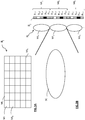
- the current full image II j is acquired conventionally using an image capture device which comprises a camera (not shown) and a lenticular network RL which is arranged between a scene SC in three dimensions and the camera .
- the lenticular network RL comprises a plurality of microlenses, of which only three microlenses ML 1 , ML 2 , ML 3 are represented on the figure 3B .
- the microlenses are all identical.
- the integral image II j is rendered on a screen (not shown) which is disposed in the focal plane of the aforementioned microlenses.
- each micro-image of the integral image II j contains several pixels of different colors, each of these pixels being representative of a given perspective of the scene SC.
- each micro-image has the same size as a microlens and therefore only three micro-images MI 1 , MI 2 and MI 3 are represented, respectively in correspondence with the three microlenses ML 1 , ML 2 , ML 3 .
- each micro-image is composed for example of five pixels of different colors. For a given micro-image MI i (1 ⁇ i ⁇ N), the latter contains five pixels P i, 1 , P i, 2 , P i, 3 , P i, 4 , P i, 5 .
- each angle of incidence corresponds to a particular viewing angle according to which an observer has the possibility of viewing the scene SC.
- the values of these angles are within the characteristic angular range of a microlens considered.
- Such an angular range corresponding, for example, to that of the microlens ML 2 , is represented in bold and solid lines on the figure 3B for illustrative purposes.
- the image capture device is configured to adapt the number of microlenses that constitute it and the resolution of the latter.
- any integral image acquired by such an image-capturing device is characterized by a given number of micro-images and a given resolution for each of these micro-images, these two numbers constituting parameters associated with the capture device. images.
- the current integral image II j is decomposed into at least one view V u from said plurality of micro-images constituting the current integral image II j and the resolution thereof.
- Step C1 is implemented by a processing software module MDCV_CO as shown in FIG. figure 2 .
- the current integral image II j is decomposed for example into a single view V 1 which contains by example the pixel placed in the center of the micro-image MI 1 , the pixel placed in the center of the micro-image MI 2 , ..., the pixel placed in the center of the micro-image MI N.
- the central pixel of each micro-image is symbolized by "x c ".
- step C2 it is proceeded to the coding of said at least one view V u .
- step C2 is implemented by a software coding module MCV_CO views as shown on the figure 2 , which module is controlled by the microprocessor .mu.P of UT_CO processing unit.
- a substep C21 for predicting said view V u is performed by known intra and / or inter prediction techniques.
- the view V u is divided into groups of pixels, for example blocks of pixels, each block being predicted with respect to at least one predictor block according to a prediction mode selected from a plurality of predetermined prediction modes. For example, in the case of HEVC encoding in the Intra prediction mode, there are thirty-five predetermined prediction modes.
- Such a predictor block is a block of pixels that has already been coded or coded and then decoded or not. Such a predictor block is stored beforehand in the buffer memory TAMP_CO of the encoder CO as represented in FIG. figure 2 .
- an optimal predictor block is obtained following a competition of said predetermined prediction modes, for example by minimizing a distortion rate criterion well known to those skilled in the art.
- the optimal predictor block is considered as an approximation of the considered block.
- Such sub-step C21 is implemented by the prediction module PRED1_CO represented on the figure 2 .
- the coding step C2 also comprises a substep C22 in which the difference between each block of the view V u and each corresponding optimal predictor block which has been selected during the sub-step is calculated. step C21.
- a plurality of residual data blocks is then obtained at the end of the substep C22, these residual blocks constituting a residual view Vr u .
- Such a sub-step C22 is implemented by the calculation module CAL1_CO represented on the figure 2 .
- the coding step C2 also comprises a substep C23 during which each block of residual data is transformed according to a conventional direct transformation operation such as, for example, a transformation of the DCT, DST or DWT type, to produce a plurality of transformed blocks which constitute the transformed view V u , designated by the reference Vt u .
- a conventional direct transformation operation such as, for example, a transformation of the DCT, DST or DWT type, to produce a plurality of transformed blocks which constitute the transformed view V u , designated by the reference Vt u .
- Such an operation is performed by the MT1_CO module represented on the figure 2 .
- the coding step C2 also comprises a sub-step C24 in which the quantization of each transformed block is carried out according to a classical quantization operation, such as, for example, scalar or vector quantization. A set Vq u of quantized coefficients is then obtained at the end of this substep.
- Such sub-step C24 is performed by means of the quantification module MQ1_CO as represented in FIG. figure 2 .
- Such a quantization sub-step is implemented using a quantization step QP 1 which is predetermined. The manner in which this parameter is determined will be described later in the description.
- Such a substep C25 entropy coding is implemented by the entropic coding module MCE1_CO shown on the figure 2 .
- the value of the quantization step QP 1 is also entropically encoded.
- the step C3 for producing such a stream is implemented by the MGF1 module for generating data streams, as represented on FIG. figure 2 .
- the signal F 1 contains the information used during the sub-step of prediction C21.
- Such information notably comprises the type of prediction (inter or intra), and if necessary, the prediction mode selected. the type of partitioning of the blocks of the view V u if the latter have been subdivided, the index of the reference view and the displacement vector used in the case where an inter prediction mode has been selected.
- Such information is coded entropically before being transmitted in the stream F 1 .
- the signal F 1 also contains the entropically coded value of the quantization step QP 1 .
- step C4 represented in FIG. figure 1 , said at least one view V u is decoded.
- step C4 is implemented by an MDV_CO views decoding software module as shown in FIG. figure 2 , which module is controlled by the microprocessor .mu.P of UT_CO processing unit.
- Such an entropy decoding sub-step C41 is implemented by the entropy decoding module MDE1_CO shown in FIG. figure 2 .
- each optimal predictor block that has been used to predict each block of the view V u is also decoded to the substep C21 of the figure 1 .
- each corresponding predictor block which is stored in the buffer memory TAMP_CO of the CO encoder of the figure 2 , is thus identified.
- Such predictor blocks are, for example, blocks of pixels which have already been decoded or not and which have been obtained in accordance with the prediction mode selected at the coding of the view V u .
- the coding step C4 also comprises a substep C42 during which the digital information obtained as a result of the substep C41 is dequantized according to a conventional dequantization operation which is the inverse operation of the quantification implemented in substep C24. A set VDq u of dequantized coefficients is then obtained at the end of this substep.
- Such substep C42 is performed by means of the dequantization module MQ1 -1 _CO as shown in FIG. figure 2 .
- Coding step C4 also comprises a substep C43 in which a transformation of the set VDq u of quantized coefficients is performed that is of type DCT -1 , DST -1 or DWT -1 .
- This transformation is the inverse operation of the transformation carried out in the substep C23.
- a plurality of decoded residual data blocks which constitute the residual decoded view V u , designated by the reference VDr u .
- Such an operation is performed by the MT1 -1 _CO module represented on the figure 2 .
- the coding step C4 also comprises a substep C44 for predicting said view V u to be decoded, by selecting the optimal predictive view consisting of the optimal predictor blocks obtained following the substep C21 mentioned above.
- Such a sub-step C44 is implemented by the prediction module PRED1 -1 _CO represented on the figure 2 .
- the coding step C4 also comprises a calculation sub-step C45, during which the decoded view VD u is constructed by adding to each of the decoded residue blocks of the decoded residual view VDr u obtained at derived from substep C43, respectively each of the corresponding predictor blocks which have been identified in substep C41 above.
- Such a sub-step C45 is implemented by the calculation module CAL1 -1 _CO represented on the figure 2 .
- a step C5 represented in FIG. figure 1 , it is proceeded to the recomposition of the current integral image II j from said at least one decoded view VD u .
- Such a step consists in applying an inverse decomposition of said decomposition of the integral image carried out in the aforementioned step C1, taking into account the resolution of said at least one view V u and its position in the current integral image II j .
- Step C5 is implemented by an MDCV -1 _CO software module for re-arrangement in views, as shown in FIG. figure 2 .
- the current recomposed integral image IIrec j consists of a single view V 1 which contains for example the pixel placed in the center of the micro-image MI 1 , the pixel placed in the center of the micro-image MI 2 , .. ., the pixel placed at the center of the micro-image MI N.
- step C6 the difference between the current integral image II j and the recomposed integral image IIrec j obtained in step C5 is calculated.
- step C6 a current residual integral image IIres j is then obtained.
- Such a step C6 is implemented by a calculation module CAL2_CO represented on the figure 2 .
- Such a current residual integral image IIres j is then considered as a two-dimensional image (2D) which undergoes 2D coding during a step C7 represented in FIG. figure 1 .
- 2D two-dimensional image
- any type of 2D coding can be applied.
- step C7 is implemented by an image coding software module MDCI, as shown in FIG. figure 2 , which module is controlled by the microprocessor .mu.P of UT_CO processing unit.
- step C7 it is proceeded to a C71 substep prediction residual of said integral image IIres j by known techniques intra prediction and / or inter.
- the residual integral image IIres j is divided into pixel groups, for instance into blocks of pixels, each block being predicted from at least one predictor block according to a prediction mode selected from a plurality of modes of predetermined prediction. For example, in the case of HEVC encoding in the Intra prediction mode, there are thirty-five predetermined prediction modes.
- Such a predictor block is a block of pixels that has already been coded or coded and then decoded or not. Such a predictor block is stored beforehand in the buffer memory TAMP_CO of the encoder CO as represented in FIG. figure 2 .
- an optimal predictor block is obtained following a competition of said predetermined prediction modes, for example by minimizing a distortion rate criterion well known to those skilled in the art.
- the optimal predictor block is considered as an approximation of the considered block.
- Such a substep C71 is implemented by the prediction module PRED2_CO represented on the figure 2 .
- the coding step C7 also comprises a substep C72 during which the difference between each block of the residual integral image IIres j is calculated and each respective optimal predictor block that has been selected during substep C71.
- a plurality of residual data blocks is then obtained at the end of the substep C72, these residual blocks constituting a residual integral image IIresr j .
- Such a substep C72 is implemented by the calculation module CAL3_CO represented on the figure 2 .
- the coding step C7 also comprises a substep C73 during which each block of residual data obtained in the substep C72 is transformed according to a conventional direct transformation operation such as, for example, a transformation of type DCT, DST or DWT, to produce a plurality of transformed blocks that constitute the transformed residual integral image, designated IIrest j .
- a conventional direct transformation operation such as, for example, a transformation of type DCT, DST or DWT, to produce a plurality of transformed blocks that constitute the transformed residual integral image, designated IIrest j .
- Such an operation is performed by the MT2_CO module represented on the figure 2 .
- the coding step C7 also comprises a substep C74 in which the quantization of each transformed block obtained in the substep C73 is performed, according to a standard quantization operation, such as for example a scalar quantization or Vector. A set IIresq u of quantized coefficients is then obtained at the end of this substep.
- Such sub-step C74 is performed by means of the quantization module MQ2_CO as represented in FIG. figure 2 .
- Such an entropy coding sub-step C75 is implemented by the entropic coding module MCE2_CO shown in FIG. figure 2 .
- the value of the quantization step QP 2 is also entropically encoded.
- the step C8 of producing such a stream is implemented by the MGF2 data flow generation module, as shown in FIG. figure 2 .
- the signal F 2 contains the information used during the prediction sub-step C71.
- Such information includes the prediction type (inter or intra), and optionally, the prediction mode selected, the type of partitioning the blocks of the residual integral image IIres j if they have been subdivided, the index of the reference integral image and the displacement vector used in the case where an inter prediction mode has been selected.
- Such information is coded entropically before being transmitted in the stream F 2 .
- the signal F 2 also contains the entropically coded value of the quantization step QP 2 .
- the data signals F 1 and F 2 are multiplexed so as to form a single signal which is transmitted to the decoder DO.
- the data signals F 1 and F 2 could be transmitted separately to the decoder DO.
- the resolution parameter of the micro-images of the current integral image II j is entropy coded either during the entropic coding sub-step C25, or during the entropy coding sub-step C75.
- the resolution parameter of the micro-images is inserted either in the data signal F 1 or in the data signal F 2 , or in another data signal (not shown) which can be transmitted separately to the decoder DO or else multiplexed with the data signals F 1 and F 2 .
- the number of views and the position of the latter are selected as those that optimize a predetermined coding performance criterion.
- the number and position of the views are selected by minimizing, for example, a distortion rate criterion well known to those skilled in the art that is applied to the coding step C2 and to the coding step C7.
- the number and position of the views are selected as those which minimize the number of data associated with the residual integral image IIres j obtained at the end of step C6 in figure 1 .
- the number and position of the views that have been selected are transmitted or not to the decoder DO.
- the value of the quantization step QP 1 used during the quantization sub-step C24 and the quantization step value QP 2 used during the quantization sub-step C74 are selected as optimizing a predetermined coding performance criterion.
- the quantization steps QP 1 and QP 2 are each selected by minimization, for example, of a distortion flow criterion well known to those skilled in the art which is applied to the coding step C2 and to the coding step C7.
- only said CI2 processing step is applied because it provides a reconstruction of the current integral image II j which is the most effective.
- transformation steps CI1, CI2 and CI3 are respectively implemented by transformation software modules TR1_CO, TR2_CO and TR3_CO, as represented in dotted line on the figure 2 .
- Each of the transformation steps CI1, CI2 and CI3 uses a corresponding transformation parameter Ptr 1 , Ptr 2 , Ptr 3 .
- the transformation parameters Ptr 1 , Ptr 2 , Ptr 3 are selected as being those which optimize a predetermined coding performance criterion.
- the latter are selected by minimizing, for example, a distortion rate criterion well known to those skilled in the art that is applied to the coding step C2 and to the coding step C7.
- the transformation parameters Ptr 1 , Ptr 2 , Ptr 3 are selected as being those which minimize the number of data associated with the residual integral image IIres j obtained at the end of step C6 in figure 1 .
- the transformation parameters Ptr 1 , Ptr 2 , Ptr 3 are transmitted or not to the decoder DO.
- An example of possible transformation is smoothing.
- the parameter associated with this transformation corresponds to the size in pixels of the smoothing filter applied to the image.
- the recomposed integral image IIrec j then contains details that do not correspond to the details of the current original integral image II j .
- a geometrical transformation (expansion, erosion, rotation, symmetry, etc.) could be applied to the said at least one view V u and / or to the said at least one reconstructed view VD u and / or to reconstituted integral image IIrec j .
- the decoding method according to the invention is represented in the form of an algorithm comprising steps D1 to D5 as represented in FIG. figure 6 .
- the decoder DO comprises a memory MEM_DO comprising a buffer memory TAMP_DO, a processing unit UT_DO equipped for example with a microprocessor ⁇ P and driven by a computer program PG_DO which implements the decoding method according to the invention.
- the code instructions of the computer program PG_DO are for example loaded into a RAM memory before being executed by the processor of the processing unit UT_DO.
- the decoding method shown in the figure 6 applies to any current integral image II j fixed to be decoded or part of a sequence of integral images II 1 , ..., II j , ..., II M ( 1 j j M M ) to be decoded .
- information representative of the current integral image decoding j II are identified in the data signal F received at the decoder, as issued following the coding method of the figure 1 .
- the identification steps D1a) and D1b) are implemented by a signal analysis module MI_DO, as represented in FIG. figure 5 , said module being driven by the microprocessor ⁇ P of the processing unit UT_DO.
- step D1a following step D1a), during a step D2 shown in FIG. figure 6 , at decoding said at least one view V u encoded entropically.
- step D2 is implemented by a view decoding software module MDV_DO as shown in FIG. figure 5 , which module is controlled by the microprocessor .mu.P of UT_DO processing unit.
- Such an entropy decoding substep D21 is implemented by the entropy decoding module MDE1_DO shown in FIG. figure 5 .
- each corresponding predictor block which is stored in the buffer TAMP_DO of the decoder DO of the figure 5 , is thus identified.
- Such predictor blocks are for example blocks of pixels which have already been decoded or not and which have been obtained according to the prediction mode selected in the coding of the view V u .
- the decoding step D2 also comprises a substep D22 during which the digital information obtained as a result of the subprocessing is decoded using the value of the quantization parameter QP 1 decoded entropically.
- step D21 according to a conventional dequantization operation which is the inverse operation of the quantization implemented during the quantization sub-step C24 of FIG. figure 1 .
- a set VDq u of dequantized coefficients is then obtained at the end of the substep D22.
- Such a sub-step D22 is performed by means of the quantization module MQ1 -1 _DO, as represented in FIG. figure 5 .
- the decoding step D2 also comprises a substep D23 during which a transformation of the set VDq u of quantized coefficients is performed which is of type DCT -1 , DST -1 or DWT -1 .
- This transformation is the inverse operation of the transformation carried out in substep C23 of the figure 1 .
- a plurality of decoded residual data blocks are obtained which constitute the residual decoded view V u , denoted by the reference VDr u .
- Such an operation is performed by the MT1 -1 _DO module represented on the figure 5 .
- the decoding step D2 also comprises a substep D24 for predicting said view V u to be decoded, by selecting the optimal predictive view consisting of the optimal predictor blocks obtained following the substep D21 mentioned above.
- Such a substep D24 is implemented by the prediction module PRED1 -1 _DO shown in FIG. figure 5 .
- the decoding step D2 also comprises a calculation sub-step D25, during which the decoded view VD u is constructed by adding to each of the decoded residue blocks of the decoded residual view VDr u obtained at the end of the decoded view. from substep D23, respectively each of the corresponding predictor blocks which have been identified in substep D21 above.
- Such a substep D25 is implemented by the calculation module CAL1 -1 _DO shown in FIG. figure 5 .
- step D3 it is proceeded to the recomposition of the current integral image II j from said at least one decoded view VD u .
- One such step is to apply a decomposition inverse of said decomposition of the integral image carried out at the coding step C1 of the figure 1 , taking into account the value of the resolution parameter p rs1 which has been decoded entropically in step D21 and the position of the said at least one view in the current integral image II j .
- step D3 a decoded reconstructed integral image is obtained which is denoted IIDrec j on the figure 6 .
- the step D3 is implemented by a software module MDCV -1 _DO of reconstruction in views, as represented on the figure 5 , said module being driven by the microprocessor ⁇ P of the processing unit UT_DO.
- the integral image II j to be decoded is then blended in one or more views, as shown in the examples of Figures 4A and 4B .
- step D1b following step D1b), during a step D4 shown in FIG. figure 6 , Decoding in two dimensions of the current residual integral image IIres j which has been coded in step C4 shown in figure 1 .
- the type of 2D decoding performed is in accordance with the type of 2D coding implemented in step C7 of FIG. figure 1 .
- step D4 is implemented by an image decoding software module MDDI, as shown in FIG. figure 5 , which module is controlled by the microprocessor .mu.P of UT_DO processing unit.
- Such an entropy decoding sub-step D41 is implemented by the entropy decoding module MDE2_DO shown in FIG. figure 5 .
- each optimal predictor block which has been used to predict each block of the current residual integral image IIres j during the substep C71 of the present invention is also decoded. figure 1 .
- each corresponding predictor block which is stored in the buffer TAMP_DO of the decoder DO of the figure 5 , is thus identified.
- Such predictor blocks are, for example, blocks of pixels which have already been decoded or not and which have been obtained in accordance with the prediction mode selected in the coding of the current residual integral image IIres j .
- the decoding step D4 also comprises a substep D42 during which dequantization, using the value of the quantization parameter QP 2 decoded entropically, the digital information obtained as a result of the sub-step D42.
- step D41 according to a conventional operation of dequantization which is the inverse operation of the quantization implemented during the quantization sub-step C74 of FIG. figure 1 .
- a set IIDresq j dequantized coefficient is then obtained after D42 sub-step.
- Such a sub-step D42 is performed by means of the quantization module MQ2 -1 _DO, as represented in FIG. figure 5 .
- the decoding step D4 also comprises a substep D43 during which a transformation of the set IIDresq j of quantized coefficients which is of type DCT -1 , DST -1 or DWT -1 is carried out .
- This transformation is the inverse operation of the transformation carried out in the substep C73 of the figure 1 .
- a plurality of decoded residual data blocks are obtained which constitute the decoded residual integral image, designated by the reference IIDresr j .
- Such an operation is performed by the MT2 -1 _DO module represented on the figure 5 .
- the D4 decoding step further comprises a substep D44 prediction residual of said integral image IIres j to be decoded, by selection of the residual integral image consisting optimal predictor optimal predictor blocks obtained as a result of the substep D41 supra.
- Such a sub-step D44 is implemented by the prediction module PRED2 -1 _DO represented on the figure 5 .
- the decoding step D4 also comprises a calculation sub-step D45, during which the decoded residual integral image IIDres j is constructed by adding to each of the decoded residue blocks of the decoded residual integral image. IIDresr j obtained at the end of substep D43, respectively each of the corresponding predictor blocks that have been identified in substep D41 supra.
- Such a sub-step D45 is implemented by the calculation module CAL2 -1 _DO shown in FIG. figure 5 .
- step D5 a current decoded integral image IID j is then obtained.
- Such a step D5 is implemented by a calculation software module CAL3 -1 _DO represented on the figure 5 .
- transformation steps DI1, DI2, DI3 are respectively implemented by transformation software modules TR1_DO, TR2_DO and TR3_DO, as represented in dashed line on the figure 5 .
- Each of the transformation steps DI1, DI2 and DI3 uses a corresponding transformation parameter Ptr 1 , Ptr 2 , Ptr 3 .
Description
La présente invention se rapporte de manière générale au domaine du traitement d'images, et plus précisément au codage et au décodage d'images intégrales et de séquences d'images intégrales.The present invention relates generally to the field of image processing, and more specifically to the encoding and decoding of integral images and integral image sequences.
L'invention peut notamment, mais non exclusivement, s'appliquer au codage vidéo mis en oeuvre dans les codeurs vidéo actuels AVC et HEVC et leurs extensions (MVC, 3D-AVC, MV-HEVC, 3D-HEVC, etc), et au décodage vidéo correspondant.The invention may especially, but not exclusively, apply to video coding implemented in current AVC and HEVC video encoders and their extensions (MVC, 3D-AVC, MV-HEVC, 3D-HEVC, etc.), and to corresponding video decoding.
L'imagerie intégrale est une technique consistant à représenter des images en relief. Elle est considérée comme particulièrement prometteuse dans le développement de la télévision 3D, notamment en raison du fait qu'elle propose, non pas une visualisation stéréoscopique des images, mais une parallaxe totale.Integral imaging is a technique of representing relief images. It is considered particularly promising in the development of 3D television, especially because it offers, not a stereoscopic visualization of images, but a total parallax.
Une image intégrale est classiquement composée de différentes images élémentaires appelées également micro-images qui représentent chacune différentes perspectives d'une scène en trois dimensions. Une image intégrale est acquise à l'aide d'un dispositif de capture d'images qui comprend une caméra et un réseau lenticulaire qui est disposé entre la scène en trois dimensions et la caméra.An integral image is conventionally composed of different elementary images also called micro-images that each represent different perspectives of a three-dimensional scene. An integral image is acquired using an image capture device that includes a camera and a lenticular array that is disposed between the three-dimensional scene and the camera.
La compression d'une image intégrale revient ainsi à compresser l'ensemble des micro-images qui la constituent.The compression of an integral image thus amounts to compressing all the micro-images that constitute it.
Malgré l'attractivité d'une telle technique, des difficultés existent pour implémenter en pratique les systèmes d'imagerie intégrale. Par exemple, dans le cas où certaines applications imposent une résolution élevée de l'image intégrale et un grand nombre de points de vue, il est nécessaire d'augmenter non seulement la taille de chaque micro-image composant cette image intégrale, mais également le nombre de micro-images de cette dernière. Il en résulte une augmentation beaucoup trop importante de la taille de l'image intégrale ainsi constituée. Ainsi, lorsque l'image intégrale doit être codée, il y a un volume élevé d'informations à comprimer et la compression de l'image intégrale est peu performante.Despite the attractiveness of such a technique, difficulties exist to implement in practice the integral imaging systems. For example, in the case where certain applications impose a high resolution of the integral image and a large number of points of view, it is necessary to increase not only the size of each micro-image composing this integral image, but also the number of micro-images of the latter. This results in a much larger increase in the size of the integral image thus formed. So when the image Integral must be encoded, there is a high volume of information to compress, and the compression of the integral image is inefficient.
Deux méthodes de codage différentes sont généralement proposées pour comprimer une image intégrale.Two different coding methods are generally proposed for compressing an integral image.
La première méthode de codage consiste à appliquer un codage en deux dimensions (2D) à l'image intégrale en tant que telle. A cet effet, les caractéristiques d'un codec 2D classique sont modifiées pour s'adapter à la structure particulière des images intégrales. Selon un premier exemple, dans les documents
L'inconvénient majeur d'une telle première méthode réside dans le fait que la résolution de l'image intégrale étant très élevée, cette dernière est difficile à coder. Cette première méthode oblige à comprimer un volume élevé d'informations, ce qui la rend peu performante.The major disadvantage of such a first method lies in the fact that the resolution of the integral image is very high, the latter is difficult to code. This first method forces to compress a high volume of information, which makes it inefficient.
La deuxième méthode de codage consiste à décomposer l'image intégrale en une pluralité de vues qui représentent chacune une scène 3D selon une position angulaire de visualisation spécifique. Chaque pixel ou zone de pixels associé à une vue considérée enregistre les informations relatives aux rayons lumineux réfléchis par un objet en perspective dans la scène, selon une même direction. Un codage 3D est ensuite appliqué aux vues ainsi obtenues. Par exemple, dans les documents
Un inconvénient de cette deuxième méthode de codage est que son application pratique impose une limitation du nombre de vues à coder par la technique de codage MVC. De plus, pour reconstruire l'image intégrale dans sa totalité, une résolution élevée pour les vues ou un nombre élevé de vues est nécessaire car ces vues doivent contenir toute l'information angulaire contenue dans l'image intégrale qui est par la suite reconstruite au décodeur.A disadvantage of this second coding method is that its practical application imposes a limitation of the number of views to be coded by the MVC coding technique. In addition, to reconstruct the whole image in its entirety, a high resolution for the views or a large number of views is necessary because these views must contain all the angular information contained in the integral image which is subsequently reconstructed at decoder.
Une troisième méthode de codage est décrite dans le document suivant:
Un des buts de l'invention est de remédier à des inconvénients de l'état de la technique précitée.One of the aims of the invention is to overcome disadvantages of the state of the art mentioned above.
A cet effet, un objet de la présente invention concerne un procédé de codage d'au moins une image intégrale courante capturée par un dispositif de capture d'images, comprenant les étapes suivantes :
- décomposer l'image intégrale courante en au moins une vue représentant une perspective donnée d'une scène et à partir d'au moins un paramètre de capture d'image associé au dispositif de capture d'images,
- coder ladite au moins une vue,
- décoder ladite au moins vue,
- recomposer l'image intégrale courante à partir de ladite au moins une vue décodée par application d'une décomposition inverse de la décomposition de l'image intégrale et à partir dudit au moins un paramètre de capture d'image associé au dispositif de capture d'images,
- déterminer une image intégrale résiduelle par comparaison de ladite au moins une image intégrale courante avec ladite image intégrale recomposée,
- coder les données associées à l'image intégrale résiduelle et ledit au moins un paramètre de capture d'image associé au dispositif de capture d'images.
- decomposing the current integral image into at least one view representing a given perspective of a scene and from at least one image capture parameter associated with the image capture device,
- coding said at least one view,
- decode said at least one view,
- recomposing the current integral image from said at least one decoded view by applying an inverse decomposition of the decomposition of the integral image and from said at least one image capture parameter associated with the capture device of pictures
- determining a residual integral image by comparing said at least one current integral image with said reconstructed integral image,
- encoding the data associated with the residual full image and said at least one image capture parameter associated with the image capture device.
Ainsi, même si la ou les vues obtenues après décomposition de l'image intégrale courante ont une faible résolution, ce qui permet de coder un nombre réduit d'informations angulaires, les données de l'image intégrale courante qui sont perdues à l'issue d'un tel codage 3D sont introduites dans l'image intégrale résiduelle qui est déterminée et dont les valeurs pixelliques sont généralement faibles, donc peu coûteuses à coder.Thus, even if the one or more views obtained after decomposition of the current integral image have a low resolution, which makes it possible to encode a reduced number of angular information, the data of the current integral image which are lost at the end of such a 3D coding are introduced into the residual integral image which is determined and whose pixellic values are generally low, therefore inexpensive to code.
Le codage d'une image intégrale selon l'invention est donc beaucoup moins coûteux en nombre de données à coder que les méthodes de codage de l'art antérieur exposées ci-dessus.The coding of an integral image according to the invention is therefore much less expensive in the number of data to be encoded than the coding methods of the prior art described above.
De façon connue en soi, la recomposition d'une image intégrale nécessite la connaissance d'au moins un paramètre de capture d'image associé au dispositif de capture d'images, tel que par exemple la résolution des micro-images constitutives de l'image intégrale ainsi que le nombre de ces micro-images.In a manner known per se, the recomposition of an integral image requires the knowledge of at least one image capture parameter associated with the image capture device, such as, for example, the resolution of the micro-images constituting the image. integral image as well as the number of these micro-images.
Selon un mode de réalisation particulier, le procédé de codage comprend :
- une étape d'élaboration d'un premier signal de données contenant des données issues du codage de la au moins une vue,
- une étape d'élaboration d'un deuxième signal de données contenant les données associées à l'image intégrale résiduelle codées,
- a step of producing a first data signal containing data from the coding of the at least one view,
- a step of producing a second data signal containing the data associated with the coded residual integral image,
Compte tenu de l'obtention d'un nombre réduit de données codées à l'issue du procédé de codage selon l'invention, une telle disposition permet avantageusement de réduire de façon notable le coût de signalisation de telles données codées à destination d'un décodeur.Given the fact that a small number of coded data are obtained at the end of the coding method according to the invention, such an arrangement advantageously makes it possible to significantly reduce the cost of signaling such coded data destined for a particular user. decoder.
Selon un autre mode de réalisation particulier, le nombre et la position des vues à coder de l'image intégrale courante sont sélectionnés comme étant ceux qui optimisent un critère de performance de codage prédéterminé.According to another particular embodiment, the number and the position of the views to be encoded of the current integral image are selected as being those which optimize a predetermined coding performance criterion.
Une telle disposition permet de tester plusieurs possibilités de coder une image intégrale courante conformément au procédé de codage selon l'invention, avec une seule vue, deux vues, trois vues, etc..., puis, selon le contexte de codage, de sélectionner le codage qui satisfait le meilleur compromis entre un nombre réduit de données à coder susceptible d'être obtenu et une qualité élevée de restitution de l'image intégrale reconstruite.Such an arrangement makes it possible to test several possibilities of coding a current integral image in accordance with the coding method according to the invention, with a single view, two views, three views, etc., and then, depending on the coding context, to select the coding which satisfies the best compromise between a reduced number of data to be coded that can be obtained and a high quality of reproduction of the reconstructed integral image.
Selon un autre mode de réalisation particulier, le nombre et la position des vues de l'image intégrale courante sont sélectionnés comme étant ceux qui minimisent le nombre de données associées à l'image intégrale résiduelle.According to another particular embodiment, the number and the position of the views of the current integral image are selected as those which minimize the number of data associated with the residual integral image.
Une telle disposition permet de tester plusieurs possibilités de coder une image intégrale courante conformément au procédé de codage selon l'invention, avec une seule vue, deux vues, trois vues, etc..., puis de sélectionner le codage pour lequel les pixels de l'image intégrale résiduelle déterminée sont les plus proches d'une valeur prédéterminée, par exemple zéro.Such an arrangement makes it possible to test several possibilities of coding a current integral image in accordance with the coding method according to the invention, with a single view, two views, three views, etc., and then to select the coding for which the pixels of the residual integral image determined are the closest to a predetermined value, for example zero.
Selon un autre mode de réalisation particulier, il est procédé à une sélection d'une valeur d'un premier paramètre de quantification à appliquer au cours de l'étape de codage de ladite au moins une vue et à une sélection d'une valeur d'un deuxième paramètre de quantification à appliquer au cours de l'étape de codage des données associées à l'image intégrale résiduelle, lesdites valeurs étant sélectionnées comme optimisant un critère de performance de codage prédéterminé.According to another particular embodiment, a value of a first quantization parameter to be applied during the coding step of the said at least one view is selected and a selection of a value of a second quantization parameter to be applied during the coding step of the data associated with the residual integral image, said values being selected as optimizing a predetermined coding performance criterion.
Une telle disposition permet de tester plusieurs pas de quantification différents lors du codage de ladite au moins une vue et des données associées à l'image intégrale résiduelle, et, selon le contexte de codage, de satisfaire un compromis entre la sévérité plus ou moins élevée (c'est-à-dire pas de quantification plus ou moins élevé) avec laquelle lesdites données vont être codées et une qualité plus ou moins élevée de restitution de l'image intégrale reconstruite.Such an arrangement makes it possible to test several different quantization steps during the coding of the said at least one view and the data associated with the residual integral image, and, depending on the coding context, to satisfy a compromise between the higher or lower severity. (That is to say, no quantization more or less high) with which said data will be encoded and a higher or lower quality of restitution of the reconstructed integral image.
Ainsi, en fonction du contexte de codage, un tel compromis sera appliqué plutôt à l'étape de codage de ladite au moins une vue, ou bien plutôt à l'étape de codage des données associées à l'image intégrale résiduelle.Thus, depending on the coding context, such a compromise will be applied rather to the coding step of the said at least one view, or rather to the coding step of the data associated with the residual integral image.
Selon un autre mode de réalisation particulier, le procédé de codage selon l'invention comprend en outre une étape de transformation d'image qui est appliquée:
- entre l'étape de décomposition de l'image intégrale courante en ladite au moins une vue et l'étape de codage de ladite au moins une vue, et/ou
- entre l'étape de décodage de ladite au moins une vue et l'étape de recomposition de l'image intégrale courante, et/ou
- entre l'étape de recomposition de l'image intégrale courante et l'étape de détermination de l'image intégrale résiduelle.
- between the step of decomposing the current integral image into said at least one view and the step of encoding said at least one view, and / or
- between the step of decoding said at least one view and the step of recomposing the current integral image, and / or
- between the step of recomposition of the current integral image and the step of determining the residual integral image.
L'avantage d'une telle transformation d'image est de réduire la quantité de données à coder de l'image intégrale résiduelle. Ce qui implique d'obtenir une image intégrale recomposée qui ressemble au mieux à l'image intégrale originale, et donc de permettre une recomposition efficace.The advantage of such an image transformation is to reduce the amount of data to be encoded of the residual integral image. This implies to obtain a reconstructed integral image that best resembles the original integral image, and thus to allow an effective recomposition.
Une telle transformation d'image consiste par exemple en un filtrage, lissage d'image ou bien encore en une transformation géométrique d'image (dilatation, érosion, rotation, symétrie, etc...) qui permet de compenser la perte d'informations introduite par la décomposition de l'image intégrale courante en au moins une vue.Such an image transformation consists, for example, in filtering, image smoothing or even in a geometrical image transformation (expansion, erosion, rotation, symmetry, etc.) that makes it possible to compensate for the loss of information. introduced by decomposing the current integral image into at least one view.
Selon un autre mode de réalisation particulier, l'étape de transformation d'image précitée est mise en oeuvre à l'aide d'un paramètre de transformation qui est sélectionné comme optimisant un critère de performance de codage prédéterminé ou bien comme minimisant le nombre de données associées à l'image intégrale résiduelle.According to another particular embodiment, the aforementioned image transformation step is implemented using a transformation parameter which is selected as optimizing a predetermined coding performance criterion or as minimizing the number of data associated with the residual integral image.
L'invention concerne également un dispositif de codage d'au moins une image intégrale courante capturée par un dispositif de capture d'images, comprenant :
- un premier module de traitement pour décomposer l'image intégrale courante en au moins une vue représentant une perspective donnée d'une scène et à partir d'au moins un paramètre de capture d'image associé au dispositif de capture d'images,
- un premier module de codage pour coder ladite au moins une vue,
- un module de décodage pour décoder ladite au moins une vue,
- un deuxième module de traitement pour recomposer l'image intégrale courante à partir de ladite vue décodée, par application d'une décomposition inverse de ladite décomposition de l'image intégrale et à partir dudit au moins un paramètre de capture d'image associé au dispositif de capture d'images,
- un module de calcul pour déterminer une image intégrale résiduelle par comparaison de ladite au moins une image intégrale courante avec ladite image intégrale recomposée,
- un deuxième module de codage pour coder les données associées à l'image intégrale résiduelle et ledit au moins un paramètre de capture d'image associé au dispositif de capture d'images.
- a first processing module for decomposing the current integral image into at least one view representing a given perspective of a scene and from at least one image capture parameter associated with the image capture device,
- a first coding module for coding said at least one view,
- a decoding module for decoding said at least one view,
- a second processing module for recomposing the current integral image from said decoded view, by applying an inverse decomposition of said decomposition of the integral image and from said at least one image capture parameter associated with the device image capture,
- a calculation module for determining a residual integral image by comparing said at least one current integral image with said reconstructed integral image,
- a second coding module for encoding the data associated with the residual integral image and said at least one image capture parameter associated with the image capture device.
Un tel dispositif de codage est notamment apte à mettre en oeuvre le procédé de codage précité.Such a coding device is particularly suitable for implementing the aforementioned coding method.
L'invention concerne aussi un procédé de décodage d'un signal de données représentatif d'au moins une image intégrale courante acquise par un dispositif de capture d'images et qui a été précédemment codée, ledit procédé comprenant les étapes suivantes :
- identifier dans le signal de données au moins un paramètre de capture d'image associé au dispositif de capture d'images,
- décoder au moins une vue de l'image intégrale courante à partir dudit au moins un paramètre de capture d'image identifié, ladite au moins une vue représentant une perspective donnée d'une scène,
- recomposer une image intégrale en tant que prédicteur de l'image intégrale courante, à partir de ladite au moins une vue décodée et à partir dudit au moins un paramètre de capture d'image associé au dispositif de capture d'images,
- décoder des données codées représentatives de la différence entre ladite au moins image intégrale courante et l'image intégrale recomposée,
- reconstruire l'image intégrale courante à partir de ladite image intégrale recomposée et des données décodées représentatives de ladite différence.
- identify in the data signal at least one image capture parameter associated with the image capture device,
- decoding at least one view of the current integral image from said at least one identified image capture parameter, said at least one view representing a given perspective of a scene,
- recomposing an integral image as a predictor of the current integral image from said at least one decoded view and from said at least one image capture parameter associated with the image capture device,
- decoding coded data representative of the difference between said at least current integral image and the reconstructed integral image,
- reconstructing the current integral image from said recomposed integral image and decoded data representative of said difference.
Compte tenu de l'obtention d'un nombre réduit de données codées à l'issue du procédé de codage selon l'invention et donc de la réduction du coût de signalisation de ces données codées au décodeur, une telle disposition permet avantageusement de décoder un nombre de données moins important que dans l'art antérieur moyennant une qualité de reconstruction de l'image intégrale qui s'avère satisfaisante. Il en résulte un décodage plus efficace.Given the fact that a small number of coded data are obtained at the end of the coding method according to the invention and therefore the reduction of the cost of signaling these coded data to the decoder, such an arrangement advantageously makes it possible to decode an less data than in the prior art with a reconstruction quality of the integral image which proves satisfactory. This results in more efficient decoding.
Selon un mode de réalisation particulier, l'étape de recomposition de l'image intégrale courante est mise en oeuvre à l'aide d'un paramètre de position de ladite au moins une vue décodée dans l'image intégrale courante à décoder, un tel paramètre de position étant prédéterminé ou bien lu dans le signal de données.According to a particular embodiment, the step of recomposition of the current integral image is implemented using a position parameter of said at least one decoded view in the current integral image to be decoded, such position parameter being predetermined or read in the data signal.
Dans le cas où le paramètre de position de ladite au moins une vue est prédéterminé, une telle information est connue à la fois au codage et au décodage. L'avantage de cette disposition est d'optimiser la réduction du coût de codage et d'éviter d'indiquer le paramètre de position dans le signal de données, ce qui permet d'optimiser le coût de signalisation.In the case where the position parameter of said at least one view is predetermined, such information is known both to the coding and the decoding. The advantage of this arrangement is to optimize the reduction of the coding cost and to avoid indicating the position parameter in the data signal, which makes it possible to optimize the cost of signaling.
Dans le cas où le paramètre de position de ladite au moins une vue est identifié dans le signal de données, cela signifie qu'une telle information a été nécessairement sélectionnée de façon optimale au codage, ce qui permet d'optimiser les performances de décodage de l'image intégrale courante.In the case where the position parameter of said at least one view is identified in the data signal, it means that such information has necessarily been optimally selected for the coding, which makes it possible to optimize the decoding performance of the data signal. the current integral image.
Selon un autre mode de réalisation particulier :
- l'étape de décodage de ladite au moins une vue comprend la mise en oeuvre d'une étape de déquantification à partir d'un premier paramètre de quantification dont la valeur est identifiée dans le signal de données,
- l'étape de décodage des données codées représentatives de la différence entre ladite au moins image intégrale courante et l'image intégrale recomposée comprend la mise en oeuvre d'une étape de déquantification à partir d'un deuxième paramètre de quantification dont la valeur est identifiée dans le signal de données.
- the step of decoding said at least one view comprises the implementation of a dequantization step from a first quantization parameter whose value is identified in the data signal,
- the step of decoding the coded data representative of the difference between said at least current integral image and the reconstructed integral image comprises the implementation of a dequantization step from a second quantization parameter whose value is identified in the data signal.
Selon un autre mode de réalisation particulier, le procédé de décodage comprend en outre une étape de transformation d'image à partir d'un paramètre de transformation prédéterminé ou bien lu dans le signal de données, une telle étape de transformation étant appliquée:
- entre l'étape de décodage de ladite au moins une vue et l'étape de recomposition de l'image intégrale courante en tant que prédicteur de l'image intégrale courante, et/ou
- entre l'étape de recomposition de l'image intégrale courante en tant que prédicteur de l'image intégrale courante et l'étape de reconstruction de l'image intégrale courante.
- between the step of decoding said at least one view and the step of recomposing the current integral image as a predictor of the current integral image, and / or
- between the step of recomposing the current integral image as a predictor of the current integral image and the step of reconstructing the current integral image.
L'invention concerne également un dispositif de décodage d'un signal de données représentatif d'au moins une image intégrale courante acquise par un dispositif de capture d'images et qui a été précédemment codée, le dispositif de décodage comprenant :
- un module d'analyse pour identifier dans le signal de données au moins un paramètre de capture d'image associé au dispositif de capture d'images,
- un premier module de décodage pour décoder au moins une vue de l'image intégrale courante à partir dudit au moins un paramètre de capture d'image identifié, ladite au moins une vue représentant une perspective donnée d'une scène,
- un module de traitement pour recomposer une image intégrale en tant que prédicteur de l'image intégrale courante, à partir de ladite vue décodée et à partir dudit au moins un paramètre de capture d'image associé au dispositif de capture d'images,
- un deuxième module de décodage pour décoder des données codées représentatives de la différence entre ladite au moins une image intégrale courante et l'image intégrale recomposée,
- un module de reconstruction pour reconstruire l'image intégrale courante à partir de ladite image intégrale recomposée et des données décodées représentatives de ladite différence.
- an analysis module for identifying in the data signal at least one image capture parameter associated with the image capture device,
- a first decoding module for decoding at least one view of the current integral image from said at least one identified image capture parameter, said at least one view representing a given perspective of a scene,
- a processing module for recomposing an integral image as a predictor of the current integral image, from said decoded view and from said at least one image capture parameter associated with the image capture device,
- a second decoding module for decoding encoded data representative of the difference between said at least one current integral image and the reconstructed integral image,
- a reconstruction module for reconstructing the current integral image from said recomposed integral image and decoded data representative of said difference.
L'invention concerne encore les programmes d'ordinateur definis par les revendications indépendantes 9 et 15. Ces programmes peuvent utiliser n'importe quel langage de programmation, et être sous la forme de code source, code objet, ou de code intermédiaire entre code source et code objet, tel que dans une forme partiellement compilée, ou dans n'importe quelle autre forme souhaitable.The invention also relates to the computer programs defined by the
Un exemple vise également un support d'enregistrement lisible par un ordinateur sur lequel est enregistré un programme d'ordinateur, ce programme comportant des instructions adaptées à la mise en oeuvre de l'un des procédés de codage ou de décodage selon l'invention, tels que décrits ci-dessus.An example also relates to a computer-readable recording medium on which a computer program is recorded, this program comprising instructions adapted to the implementation of one of the coding or decoding methods according to the invention, as described above.
Un autre exemple vise également un support d'enregistrement lisible par un ordinateur sur lequel est enregistré un programme d'ordinateur, ce programme comportant des instructions adaptées à la mise en oeuvre du procédé de codage ou de décodage selon l'invention, tels que décrits ci-dessus.Another example also relates to a computer-readable recording medium on which a computer program is recorded, this program including instructions adapted to the implementation of the coding or decoding method according to the invention, as described. above.
Le support d'enregistrement peut être n'importe quelle entité ou dispositif capable de stocker le programme. Par exemple, le support peut comporter un moyen de stockage, tel qu'une ROM, par exemple un CD ROM ou une ROM de circuit microélectronique, ou encore un moyen d'enregistrement magnétique, par exemple une clé USB ou un disque dur.The recording medium may be any entity or device capable of storing the program. For example, the medium may include storage means, such as a ROM, for example a CD ROM or a microelectronic circuit ROM, or a magnetic recording means, for example a USB key or a hard disk.
D'autre part, le support d'enregistrement peut être un support transmissible tel qu'un signal électrique ou optique, qui peut être acheminé via un câble électrique ou optique, par radio ou par d'autres moyens. Le programme selon l'invention peut être en particulier téléchargé sur un réseau de type Internet.On the other hand, the recording medium may be a transmissible medium such as an electrical or optical signal, which may be conveyed via an electrical or optical cable, by radio or by other means. The program according to the invention can be downloaded in particular on an Internet type network.
Alternativement, le support d'enregistrement peut être un circuit intégré dans lequel le programme est incorporé, le circuit étant adapté pour exécuter ou pour être utilisé dans l'exécution du procédé de codage ou de décodage précité.Alternatively, the recording medium may be an integrated circuit in which the program is incorporated, the circuit being adapted to execute or to be used in the execution of the aforementioned coding or decoding method.
D'autres caractéristiques et avantages apparaîtront à la lecture d'un mode de réalisation préféré décrit en référence aux figures dans lesquelles:
- la
figure 1 représente les étapes du procédé de codage selon un mode de réalisation de l'invention, - la
figure 2 représente un mode de réalisation d'un dispositif de codage selon l'invention, - la
figure 3A représente un exemple d'image intégrale, - la
figure 3B représente un exemple d'acquisition d'image intégrale au moyen d'un dispositif de capture d'images, - la
figure 4A représente un exemple de décomposition de l'image intégrale en une seule vue, - la
figure 4B représente un exemple de décomposition de l'image intégrale en plusieurs vues, - la
figure 5 représente un mode de réalisation d'un dispositif de décodage selon l'invention, - la
figure 6 représente les principales étapes du procédé de décodage selon l'invention.
- the
figure 1 represents the steps of the coding method according to one embodiment of the invention, - the
figure 2 represents an embodiment of a coding device according to the invention, - the
figure 3A represents an example of an integral image, - the
figure 3B represents an example of integral image acquisition by means of an image capture device, - the
Figure 4A represents an example of decomposition of the integral image into a single view, - the
Figure 4B represents an example of decomposition of the integral image into several views, - the
figure 5 represents an embodiment of a decoding device according to the invention, - the
figure 6 represents the main steps of the decoding method according to the invention.
Un mode de réalisation de l'invention va maintenant être décrit, dans lequel le procédé de codage selon l'invention est utilisé pour coder une image intégrale ou une séquence d'images intégrales selon un signal binaire proche de celui qu'on obtient par un codage mis en oeuvre dans un codeur conforme à l'une quelconque des normes de codage vidéo actuelles ou à venir.An embodiment of the invention will now be described, in which the coding method according to the invention is used to encode an integral image or a sequence of integral images according to a binary signal close to that obtained by a coding implemented in an encoder according to any one of the current or future video coding standards.
Dans ce mode de réalisation, le procédé de codage selon l'invention est par exemple implémenté de manière logicielle ou matérielle par modifications d'un tel codeur. Le procédé de codage selon l'invention est représenté sous la forme d'un algorithme comportant des étapes C1 à C8 telles que représentées à la
Selon le mode de réalisation de l'invention, le procédé de codage selon l'invention est implémenté dans un dispositif de codage ou codeur CO représenté à la
Comme illustré en
Le procédé de codage représenté sur la
Comme représenté sur la
Comme représenté sur la
Le réseau lenticulaire RL comprend une pluralité de microlentilles, dont seulement trois microlentilles ML1, ML2, ML3 sont représentées sur la
Pendant l'acquisition de l'image intégrale IIj, des rayons lumineux provenant de la scène SC traversent chaque microlentille ML1, ML2, ML3, puis viennent frapper les pixels de chaque cellule du capteur, dans le plan focal desdites microlentilles. Compte tenu de la configuration particulière du réseau lenticulaire RL et de la matrice de pixels constituant l'écran, les rayons lumineux :
- frappent selon un premier angle d'incidence les pixels P1,1, P2,1, P3,1,
- frappent selon un deuxième angle d'incidence les pixels P1,2, P2,2, P3,2,
- frappent selon un troisième angle d'incidence les pixels P1,3, P2,3, P3,3,
- frappent selon un quatrième angle d'incidence les pixels P1,4, P2,4, P3,4,
- frappent selon un cinquième angle d'incidence les pixels P1,5, P2,5, P3,5.
- striking at a first angle of incidence pixels P 1.1 , P 2.1 , P 3.1 ,
- striking at a second angle of incidence the pixels P 1,2 , P 2,2 , P 3,2 ,
- strike the pixels P 1.3 , P 2.3 , P 3.3 at a third angle of incidence,
- hit at a fourth angle of incidence pixels P 1,4 , P 2,4 , P 3,4 ,
- hit at a fifth angle of incidence pixels P 1,5 , P 2,5 , P 3,5 .
De façon connue en soi, chaque angle d'incidence correspond à un angle de visualisation particulier selon lequel un observateur a la possibilité de visualiser la scène SC. Les valeurs de ces angles sont comprises dans la plage angulaire caractéristique d'une microlentille considérée. Une telle plage angulaire, correspondant par exemple à celle de la microlentille ML2, est représentée en trait plein et gras sur la
En fonction du contexte de codage souhaité, le dispositif de capture d'images est configuré de façon à adapter le nombre de microlentilles qui le constituent ainsi que la résolution de ces dernières. Ainsi, toute image intégrale acquise par un tel dispositif de capture d'images est caractérisée par un nombre donné de micro-images et une résolution donnée pour chacune de ces micro-images, ces deux nombres constituant des paramètres associés au dispositif de capture d'images.Depending on the coding context desired, the image capture device is configured to adapt the number of microlenses that constitute it and the resolution of the latter. Thus, any integral image acquired by such an image-capturing device is characterized by a given number of micro-images and a given resolution for each of these micro-images, these two numbers constituting parameters associated with the capture device. images.
Au cours d'une étape C1 représentée sur la
L'étape C1 est mise en oeuvre par un module logiciel de traitement MDCV_CO tel que représenté sur la
Selon un premier exemple, dans le cas où chacune des micro-images de l'image intégrale courante IIj contient K pixels de couleurs différentes, l'image intégrale courante IIj est décomposée en :
- une vue qui contient le premier pixel de la micro-image MI1, le premier pixel de la micro-image MI2,...., le premier pixel de la micro-image MIN,
- et/ou une vue qui contient le deuxième pixel de la micro-image MI1, le deuxième pixel de la micro-image MI2, ..., le deuxième pixel de la micro-image MIN,
- .....,
- et/ou une vue qui contient le Kième pixel de la micro-image MI1, le Kième pixel de la micro-image MI2, ..., le Kième pixel de la micro-image MIN.
- a view which contains the first pixel of the micro-image MI 1 , the first pixel of the micro-image MI 2, .... , the first pixel of the micro-image MI N ,
- and / or a view which contains the second pixel of the micro-image MI 1 , the second pixel of the micro-image MI 2 , ..., the second pixel of the micro-image MI N ,
- .....,
- and / or a view which contains the Kth pixel of the micro-image MI 1 , the Kth pixel of the micro-image MI 2 , ..., the Kth pixel of the micro-image MI N.
Selon un deuxième exemple, dans le cas où chacune des micro-images de l'image intégrale courante IIj contient K pixels de couleurs différentes, l'image intégrale courante IIj est décomposée en :
- une vue qui contient les quatre premiers pixels de la micro-image MI1, les quatre premiers pixels de la micro-image MI2,...., les quatre premiers pixels de la micro-image MIN, ces quatre premiers pixels étant constitués, pour une micro-image considérée, par exemple par les premier et deuxième pixels de la première ligne de cette micro-image, ainsi que les premier et deuxième pixels de la deuxième ligne de cette micro-image,
- et/ou une vue qui contient les quatre deuxièmes pixels de la micro-image MI1, les quatre deuxièmes pixels de la micro-image MI2,...., les quatre deuxièmes pixels de la micro-image MIN, ces quatre deuxièmes pixels étant constitués, pour une micro-image considérée, par exemple par les troisième et quatrième pixels de la première ligne de cette micro-image, ainsi que les troisième et quatrième pixels de la deuxième ligne de cette micro-image,
- .....,
- et ou une vue qui contient les quatre derniers pixels de la micro-image MI1, les quatre derniers pixels de la micro-image MI2,...., les quatre derniers pixels de la micro-image MIN, ces quatre derniers pixels étant constitués, pour une micro-image considérée, par exemple par les avant dernier et dernier pixels de l'avant dernière ligne de cette micro-image, ainsi que les avant-dernier et dernier pixels de la dernière ligne de cette micro-image.
- a view which contains the first four pixels of the micro-image MI 1 , the first four pixels of the micro-image MI 2, .... , the first four pixels of the micro-image MI N , these first four pixels being constituted, for a micro-image considered, for example by the first and second pixels of the first line of this micro-image, as well as the first and second pixels of the second line of this micro-image,
- and / or a view which contains the four second pixels of the micro-image MI 1 , the four second pixels of the micro-image MI 2, .... , the four second pixels of the micro-image MI N , these four second pixels being constituted, for a micro-image considered, for example by the third and fourth pixels of the first line of this micro-image, as well as the third and fourth pixels of the second line of this micro-image,
- .....,
- and or a view which contains the last four pixels of the micro-image MI 1 , the last four pixels of the micro-image MI 2, .... , the last four pixels of the micro-image MI N , these last four pixels being constituted, for a micro-image considered, for example by the penultimate and last pixels of the penultimate line of this micro-image, as well as the penultimate and last pixels of the last line of this micro-image .
Selon un mode de réalisation représenté sur la
Selon un autre mode de réalisation représenté sur la
- la vue V1 est celle représentée à la
figure 4A , - la vue V2 contient par exemple le pixel placé à gauche du pixel central de la micro-image MI1, le pixel placé à gauche du pixel central de la micro-image MI2, ..., le pixel placé à gauche du pixel central de la micro-image MIN. Sur la
figure 4B , le pixel placé à gauche du pixel central de chaque micro-image est symbolisé par « xg ». - la vue V3 contient par exemple le pixel placé à droite du pixel central de la micro-image MI1, le pixel placé à droite du pixel central de la micro-image MI2, ..., le pixel placé à droite du pixel central de la micro-image MIN. Sur la
figure 4B , le pixel placé à droite du pixel central de chaque micro-image est symbolisé par « xd ».
- the view V 1 is the one represented in
Figure 4A , - the view V 2 contains for example the pixel placed to the left of the central pixel of the micro-image MI 1 , the pixel placed to the left of the central pixel of the micro-image MI 2 , ..., the pixel placed to the left of the pixel central of the micro-image MI N. On the
Figure 4B , the pixel placed to the left of the central pixel of each micro-image is symbolized by "x g ". - the view V 3 contains, for example, the pixel placed to the right of the central pixel of the micro-image MI 1 , the pixel placed to the right of the central pixel of the micro-image MI 2 , ..., the pixel placed to the right of the pixel central of the micro-image MI N. On the
Figure 4B , the pixel placed to the right of the central pixel of each micro-image is symbolized by "x d ".
Au cours d'une étape C2 représentée à la
Une telle étape C2 est mise en oeuvre par un module logiciel de codage de vues MCV_CO tel que représenté sur la
Un tel module MCV_CO de codage de vues comprend classiquement :
- un module PRED1_CO de prédiction,
- un module CAL1_CO de calcul de données résiduelles,
- un module MT1_CO de transformation de type DCT (abréviation anglaise de « Discrète Cosine Transform »), DST (abréviation anglaise de « Discrète Sine Transform »), DWT (abréviation anglaise de « Discrete Wavelet Transform »)
- un module MQ1_CO de quantification,
- un module MCE1_CO de codage entropique par exemple de type CABAC ("Context Adaptive Binary Arithmetic Coder" en anglais) ou encore un codeur de Huffman connu en tant que tel.
- a prediction module PRED1_CO,
- a module CAL1_CO of calculation of residual data,
- an MT1_CO module of DCT type (abbreviation of "Discrete Cosine Transform"), DST (abbreviation of "Discrete Sine Transform"), DWT (abbreviation of "Discrete Wavelet Transform")
- a quantification module MQ1_CO,
- a module MCE1_CO entropic coding for example CABAC type ("Context Adaptive Binary Arithmetic Coder" in English) or a Huffman encoder known as such.
De façon connue en soi, au cours de l'étape C2, il est procédé à une sous-étape C21 de prédiction de ladite vue Vu par des techniques connues de prédiction intra et/ou inter. A cet effet, la vue Vu est découpée en groupes de pixels, par exemple en blocs de pixels, chaque bloc étant prédit par rapport à au moins un bloc prédicteur conformément à un mode de prédiction sélectionné parmi une pluralité de modes de prédiction prédéterminés. Par exemple, dans le cas d'un codage HEVC en mode de prédiction Intra, il y a trente-cinq modes de prédiction prédéterminés.In a manner known per se, during step C2, a substep C21 for predicting said view V u is performed by known intra and / or inter prediction techniques. For this purpose, the view V u is divided into groups of pixels, for example blocks of pixels, each block being predicted with respect to at least one predictor block according to a prediction mode selected from a plurality of predetermined prediction modes. For example, in the case of HEVC encoding in the Intra prediction mode, there are thirty-five predetermined prediction modes.
Un tel bloc prédicteur est un bloc de pixels qui a été déjà codé ou bien codé puis décodé ou non. Un tel bloc prédicteur est préalablement stocké dans la mémoire tampon TAMP_CO du codeur CO telle que représentée à la
Pour un bloc considéré de la vue Vu, un bloc prédicteur optimal est obtenu suite à une mise en compétition desdits modes de prédiction prédéterminés, par exemple par minimisation d'un critère débit distorsion bien connu de l'homme du métier. Le bloc prédicteur optimal est considéré comme une approximation du bloc considéré.For a given block of the view V u , an optimal predictor block is obtained following a competition of said predetermined prediction modes, for example by minimizing a distortion rate criterion well known to those skilled in the art. The optimal predictor block is considered as an approximation of the considered block.
A l'issue de la sous-étape C21, une vue prédictrice Vpu est obtenue.At the end of the substep C21, a predictive view Vp u is obtained.
Une telle sous-étape C21 est mise en oeuvre par le module de prédiction PRED1_CO représenté sur la
L'étape de codage C2 comprend également une sous-étape C22 au cours de laquelle il est procédé au calcul de la différence entre chaque bloc de la vue Vu et respectivement chaque bloc prédicteur optimal correspondant qui a été sélectionné au cours de la sous-étape C21.The coding step C2 also comprises a substep C22 in which the difference between each block of the view V u and each corresponding optimal predictor block which has been selected during the sub-step is calculated. step C21.
Une pluralité de blocs de données résiduelles est alors obtenue à l'issue de la sous-étape C22, ces blocs résiduels constituant une vue résiduelle Vru.A plurality of residual data blocks is then obtained at the end of the substep C22, these residual blocks constituting a residual view Vr u .
Une telle sous-étape C22 est mise en oeuvre par le module de calcul CAL1_CO représenté sur la
L'étape de codage C2 comprend également une sous-étape C23 au cours de laquelle il est procédé à la transformation de chaque bloc de données résiduelles selon une opération classique de transformation directe telle que par exemple une transformation de type DCT, DST ou DWT, pour produire une pluralité de blocs transformés qui constituent la vue Vu transformée, désignée par la référence Vtu. Une telle opération est effectuée par le module MT1_CO représenté sur la
L'étape de codage C2 comprend également une sous-étape C24 au cours de laquelle il est procédé à la quantification de chaque bloc transformé selon une opération classique de quantification, telle que par exemple une quantification scalaire ou vectorielle. Un ensemble Vqu de coefficients quantifiés est alors obtenu à l'issue de cette sous-étape. Une telle sous-étape C24 est effectuée au moyen du module MQ1_CO de quantification tel que représenté à la
Une telle sous-étape de quantification est mise en oeuvre à l'aide d'un pas de quantification QP1 qui est prédéterminé. La manière dont ce paramètre est déterminé sera décrite plus loin dans la description.Such a quantization sub-step is implemented using a quantization step QP 1 which is predetermined. The manner in which this parameter is determined will be described later in the description.
L'étape de codage C2 comprend également une sous-étape C25 au cours de laquelle il est procédé au codage de l'ensemble Vqu de coefficients selon un ordre prédéterminé, tel que notamment l'ordre « raster scan ». Dans le mode préféré de réalisation, le codage effectué est un codage entropique de type arithmétique ou de Huffman. La sous-étape C25 consiste alors à :
- lire le ou les symboles d'un ensemble prédéterminé de symboles qui sont associés à chaque bloc de données quantifié de la vue Vu,
- associer des informations numériques, telles que des bits, au(x) symbole(s) lu(s).
- reading the symbol or symbols of a predetermined set of symbols that are associated with each quantized data block of the view V u ,
- associating digital information, such as bits, with the read symbol (s).
Une telle sous-étape C25 de codage entropique est mise en oeuvre par le module de codage entropique MCE1_CO représenté sur la
Au cours de la sous-étape C25, la valeur du pas de quantification QP1 est également codée entropiquement.During the sub-step C25, the value of the quantization step QP 1 is also entropically encoded.
A l'issue de l'étape de codage C2 de la vue Vu, il est procédé, au cours d'une étape C3 représenté sur la
L'étape C3 de production d'un tel flux est mise en oeuvre par le module MGF1 de génération de flux de données, tel que représenté sur la
De façon connue en soi, le signal F1 contient les informations utilisées au cours de la sous-étape de prédiction C21 De telles informations comprennent notamment le type de prédiction (inter ou intra), et le cas échéant, le mode de prédiction sélectionné, le type de partitionnement des blocs de la vue Vu si ces derniers ont été subdivisés, l'indice de la vue de référence et le vecteur de déplacement utilisés dans le cas où un mode de prédiction inter a été sélectionné. De telles informations sont codées entropiquement avant d'être transmises dans le flux F1.In a manner known per se, the signal F 1 contains the information used during the sub-step of prediction C21. Such information notably comprises the type of prediction (inter or intra), and if necessary, the prediction mode selected. the type of partitioning of the blocks of the view V u if the latter have been subdivided, the index of the reference view and the displacement vector used in the case where an inter prediction mode has been selected. Such information is coded entropically before being transmitted in the stream F 1 .
En particulier, le signal F1 contient également la valeur codée entropiquement du pas de quantification QP1.In particular, the signal F 1 also contains the entropically coded value of the quantization step QP 1 .
Selon l'invention, au cours d'une étape C4 représentée à la
Une telle étape C4 est mise en oeuvre par un module logiciel de décodage de vues MDV_CO tel que représenté sur la
Un tel module MDV_CO de codage de vues comprend classiquement :
- un module MDE1_CO de décodage entropique, par exemple de type CABAC ("Context Adaptive Binary Arithmetic Coder" en anglais) ou encore un décodeur de Huffman connu en tant que tel,
- un module MQ1-1_CO de déquantification,
- un module MT1-1_CO de transformation inverse de type DCT-1 (abréviation anglaise de « Discrète Cosine Transform »), DST-1 (abréviation anglaise de « Discrète Sine Transform »), DWT-1 (abréviation anglaise de « Discrete Wavelet Transform »),
- un module PRED1-1_CO de prédiction inverse,
- un module CAL1-1_CO de calcul de reconstruction de vue.
- an entropy decoding module MDE1_CO, for example of CABAC type ("Context Adaptive Binary Arithmetic Coder" in English) or a Huffman decoder known as such,
- a dequantization module MQ1 -1 _CO,
- a MT1 -1 _CO module of inverse transformation of DCT -1 type (abbreviation of "Discrete Cosine Transform"), DST -1 (abbreviation of "Discrete Sine Transform"), DWT -1 (abbreviation of "Discrete Wavelet Transform") ")
- a prediction module PRED1 -1 _CO,
- a CAL1 -1 _CO module of view reconstruction calculation.
Au cours de l'étape C4, il est procédé à une sous-étape C41 de décodage entropique des données codées entropiquement associées à la vue Vu, selon un ordre prédéterminé, tel que notamment l'ordre « raster scan ». Dans le mode préféré de réalisation, le décodage effectué est un décodage entropique de type arithmétique ou de Huffman. La sous-étape C41 consiste alors à :
- lire le ou les symboles d'un ensemble prédéterminé de symboles qui sont associés à chaque bloc quantifié de la vue Vu,
- associer des informations numériques, telles que des bits, au(x) symbole(s) lu(s).
- reading the symbol or symbols of a predetermined set of symbols that are associated with each quantized block of the view V u ,
- associating digital information, such as bits, with the read symbol (s).
A l'issue de la sous-étape C41 précitée, est obtenue une pluralité d'informations numériques associées aux données quantifiées qui ont été codées au cours de l'étape C25 précitée.At the end of the substep C41 above, is obtained a plurality of digital information associated with the quantized data that was encoded during the aforementioned step C25.
Une telle sous-étape C41 de décodage entropique est mise en oeuvre par le module de décodage entropique MDE1_CO représenté sur la
Au cours de la sous-étape C41 précitée, est également décodé l'indice de chaque bloc prédicteur optimal qui a été utilisé pour prédire chaque bloc de la vue Vu à la sous-étape C21 de la
L'étape de codage C4 comprend également une sous-étape C42 au cours de laquelle il est procédé à la déquantification des informations numériques obtenues à la suite de la sous-étape C41, selon une opération classique de déquantification qui est l'opération inverse de la quantification mise en oeuvre à la sous-étape C24. Un ensemble VDqu de coefficients déquantifiés est alors obtenu à l'issue de cette sous-étape. Une telle sous-étape C42 est effectuée au moyen du module MQ1-1_CO de déquantification tel que représenté à la
L'étape de codage C4 comprend également une sous-étape C43 au cours de laquelle il est procédé à une transformation de l'ensemble VDqu de coefficients quantifiés qui est de type DCT-1, DST-1 ou DWT-1. Cette transformation est l'opération inverse de la transformation effectuée à la sous-étape C23. A l'issue de cette sous-étape, est obtenue une pluralité de blocs de données résiduelles décodés qui constituent la vue Vu résiduelle décodée, désignée par la référence VDru. Une telle opération est effectuée par le module MT1-1_CO représenté sur la
L'étape de codage C4 comprend également une sous-étape C44 de prédiction de ladite vue Vu à décoder, par sélection de la vue prédictrice optimale constituée des blocs prédicteurs optimaux obtenus à la suite de la sous-étape C21 précitée.The coding step C4 also comprises a substep C44 for predicting said view V u to be decoded, by selecting the optimal predictive view consisting of the optimal predictor blocks obtained following the substep C21 mentioned above.
Une telle sous-étape C44 est mise en oeuvre par le module de prédiction PRED1-1_CO représenté sur la
L'étape de codage C4 comprend également une sous-étape de calcul C45, au cours de laquelle il est procédé à la construction de la vue décodée VDu en ajoutant à chacun des blocs résidus décodés de la vue résiduelle décodée VDru obtenue à l'issue de la sous-étape C43, respectivement chacun des blocs prédicteurs correspondants qui ont été identifiés à la sous-étape C41 précitée.The coding step C4 also comprises a calculation sub-step C45, during which the decoded view VD u is constructed by adding to each of the decoded residue blocks of the decoded residual view VDr u obtained at derived from substep C43, respectively each of the corresponding predictor blocks which have been identified in substep C41 above.
Une telle sous-étape C45 est mise en oeuvre par le module de calcul CAL1-1_CO représenté sur la
Selon l'invention, au cours d'une étape C5 représentée à la
L'étape C5 est mise en oeuvre par un module logiciel MDCV-1_CO de recomposition en vues, tel que représenté sur la
Selon un premier exemple, dans le cas où chacune des micro-images de l'image intégrale courante IIj contient K pixels de couleurs différentes, l'image intégrale courante IIrecj est recomposée en :
- une vue qui contient le premier pixel de la micro-image MI1, le premier pixel de la micro-image MI2,...., le premier pixel de la micro-image MIN,
- et/ou une vue qui contient le deuxième pixel de la micro-image MI1, le deuxième pixel de la micro-image MI2, ..., le deuxième pixel de la micro-image MIN,
- .....,
- et/ou une vue qui contient le Kième pixel de la micro-image MI1, le Kième pixel de la micro-image MI2, ..., le Kième pixel de la micro-image MIN.
- a view which contains the first pixel of the micro-image MI 1 , the first pixel of the micro-image MI 2, .... , the first pixel of the micro-image MI N ,
- and / or a view which contains the second pixel of the micro-image MI 1 , the second pixel of the micro-image MI 2 , ..., the second pixel of the micro-image MI N ,
- .....,
- and / or a view which contains the Kth pixel of the micro-image MI 1 , the Kth pixel of the micro-image MI 2 , ..., the Kth pixel of the micro-image MI N.
Selon un deuxième exemple, dans le cas où chacune des micro-images de l'image intégrale courante IIj contient K pixels de couleurs différentes, l'image intégrale courante IIj est recomposée en :
- une vue qui contient les quatre premiers pixels de la micro-image MI1, les quatre premiers pixels de la micro-image MI2,...., les quatre premiers pixels de la micro-image MIN, ces quatre premiers pixels étant constitués, pour une micro-image considérée, par exemple par les premier et deuxième pixels de la première ligne de cette micro-image, ainsi que les premier et deuxième pixels de la deuxième ligne de cette micro-image
- et/ou une vue qui contient les quatre deuxièmes pixels de la micro-image MI1, les quatre deuxièmes pixels de la micro-image MI2,...., les quatre deuxièmes pixels de la micro-image MIN, ces quatre deuxièmes pixels étant constitués, pour une micro-image considérée, par exemple par les troisième et quatrième pixels de la première ligne de cette micro-image, ainsi que les troisième et quatrième pixels de la deuxième ligne de cette micro-image,
- .....,
- et ou une vue qui contient les quatre derniers pixels de la micro-image MI1, les quatre derniers pixels de la micro-image MI2,...., les quatre derniers pixels de la micro-image MIN, ces quatre derniers pixels étant constitués, pour une micro-image considérée, par exemple par les avant dernier et dernier pixels de l'avant dernière ligne de cette micro-image, ainsi que les avant-dernier et dernier pixels de la dernière ligne de cette micro-image.
- a view which contains the first four pixels of the micro-image MI 1 , the first four pixels of the micro-image MI 2, .... , the first four pixels of the micro-image MI N , these first four pixels being constituted, for a micro-image considered, for example by the first and second pixels of the first line of this micro-image, as well as the first and second pixels of the second line of this micro-image
- and / or a view which contains the four second pixels of the micro-image MI 1 , the four second pixels of the micro-image MI 2, .... , the four second pixels of the micro-image MI N , these four second pixels being constituted, for a micro-image considered, for example by the third and fourth pixels of the first line of this micro-image, as well as the third and fourth pixels of the second line of this micro-image,
- .....,
- and or a view which contains the last four pixels of the micro-image MI 1 , the last four pixels of the micro-image MI 2, .... , the last four pixels of the micro-image MI N , these last four pixels being constituted, for a micro-image considered, for example by the penultimate and last pixels of the penultimate line of this micro-image, as well as the penultimate and last pixels of the last line of this micro-image .
Selon le mode de réalisation représenté sur la
Selon l'autre mode de réalisation représenté sur la
- la vue V1 est celle représentée à la
figure 4A , - la vue V2 contient par exemple le pixel placé à gauche du pixel central de la micro-image MI1, le pixel placé à gauche du pixel central de la micro-image MI2, ..., le pixel placé à gauche du pixel central de la micro-image MIN,
- la vue V3 contient par exemple le pixel placé à droite du pixel central de la micro-image MI1, le pixel placé à droite du pixel central de la micro-image MI2, ..., le pixel placé à droite du pixel central de la micro-image MIN.
- the view V 1 is the one represented in
Figure 4A , - the view V 2 contains for example the pixel placed to the left of the central pixel of the micro-image MI 1 , the pixel placed to the left of the central pixel of the micro-image MI 2 , ..., the pixel placed to the left of the pixel central of the micro-image MI N ,
- the view V 3 contains, for example, the pixel placed to the right of the central pixel of the micro-image MI 1 , the pixel placed to the right of the central pixel of the micro-image MI 2 , ..., the pixel placed to the right of the pixel central of the micro-image MI N.
Selon l'invention, au cours d'une étape C6 représentée à la
A l'issue de l'étape C6, une image intégrale résiduelle courante IIresj est alors obtenue.At the end of step C6, a current residual integral image IIres j is then obtained.
Une telle étape C6 est mise en oeuvre par un module de calcul CAL2_CO représenté sur la
Une telle image intégrale résiduelle courante IIresj est alors considérée comme une image en deux dimensions (2D) qui subit un codage 2D au cours d'une étape C7 représentée à la
Une telle étape C7 est mise en oeuvre par un module logiciel MDCI de codage d'images, tel que représenté sur la
Un tel module MDCI de codage d'images en deux dimensions peut comprendre par exemple :
- un module PRED2_CO de prédiction,
- un module CAL3_CO de calcul de données résiduelles,
- un module MT2_CO de transformation de type DCT (abréviation anglaise de « Discrète Cosine Transform »), DST (abréviation anglaise de « Discrète Sine Transform »), DWT (abréviation anglaise de « Discrete Wavelet Transform »)
- un module MQ2_CO de quantification,
- un module MCE2_CO de codage entropique par exemple de type CABAC ("Context Adaptive Binary Arithmetic Coder" en anglais) ou encore un codeur de Huffman connu en tant que tel.
- a prediction module PRED2_CO,
- a module CAL3_CO of calculation of residual data,
- an MT2_CO module of DCT type (abbreviation of "Discrete Cosine Transform"), DST (abbreviation of "Discrete Sine Transform"), DWT (abbreviation of "Discrete Wavelet Transform")
- a quantification module MQ2_CO,
- an entropy encoding module MCE2_CO for example of CABAC type ("Context Adaptive Binary Arithmetic Coder" in English) or a Huffman encoder known as such.
Au cours de l'étape C7, il est procédé à une sous-étape C71 de prédiction de ladite image intégrale résiduelle IIresj par des techniques connues de prédiction intra et/ou inter. A cet effet, l'image intégrale résiduelle IIresj est découpée en groupes de pixels, par exemple en blocs de pixels, chaque bloc étant prédit par rapport à au moins un bloc prédicteur conformément à un mode de prédiction sélectionné parmi une pluralité de modes de prédiction prédéterminés. Par exemple, dans le cas d'un codage HEVC en mode de prédiction Intra, il y a trente-cinq modes de prédiction prédéterminés.In step C7, it is proceeded to a C71 substep prediction residual of said integral image IIres j by known techniques intra prediction and / or inter. For this purpose, the residual integral image IIres j is divided into pixel groups, for instance into blocks of pixels, each block being predicted from at least one predictor block according to a prediction mode selected from a plurality of modes of predetermined prediction. For example, in the case of HEVC encoding in the Intra prediction mode, there are thirty-five predetermined prediction modes.
Un tel bloc prédicteur est un bloc de pixels qui a été déjà codé ou bien codé puis décodé ou non. Un tel bloc prédicteur est préalablement stocké dans la mémoire tampon TAMP_CO du codeur CO telle que représentée à la
Pour un bloc considéré de l'image intégrale résiduelle IIresj, un bloc prédicteur optimal est obtenu suite à une mise en compétition desdits modes de prédiction prédéterminés, par exemple par minimisation d'un critère débit distorsion bien connu de l'homme du métier. Le bloc prédicteur optimal est considéré comme une approximation du bloc considéré.For a given block of the residual integral image IIres j , an optimal predictor block is obtained following a competition of said predetermined prediction modes, for example by minimizing a distortion rate criterion well known to those skilled in the art. The optimal predictor block is considered as an approximation of the considered block.
A l'issue de la sous-étape C71, une image intégrale résiduelle prédictrice IIrespj est obtenue.At the end of the substep C71, a residual integral image predictor IIresp j is obtained.
Une telle sous-étape C71 est mise en oeuvre par le module de prédiction PRED2_CO représenté sur la
L'étape de codage C7 comprend également une sous-étape C72 au cours de laquelle il est procédé au calcul de la différence entre chaque bloc de l'image intégrale résiduelle IIresj et respectivement chaque bloc prédicteur optimal correspondant qui a été sélectionné au cours de la sous-étape C71.The coding step C7 also comprises a substep C72 during which the difference between each block of the residual integral image IIres j is calculated and each respective optimal predictor block that has been selected during substep C71.
Une pluralité de blocs de données résiduelles est alors obtenue à l'issue de la sous-étape C72, ces blocs résiduels constituant une image intégrale résiduelle IIresrj.A plurality of residual data blocks is then obtained at the end of the substep C72, these residual blocks constituting a residual integral image IIresr j .
Une telle sous-étape C72 est mise en oeuvre par le module de calcul CAL3_CO représenté sur la
L'étape de codage C7 comprend également une sous-étape C73 au cours de laquelle il est procédé à la transformation de chaque bloc de données résiduelles obtenus à la sous-étape C72 selon une opération classique de transformation directe telle que par exemple une transformation de type DCT, DST ou DWT, pour produire une pluralité de blocs transformés qui constituent l'image intégrale résiduelle transformée, désignée par la référence IIrestj. Une telle opération est effectuée par le module MT2_CO représenté sur la
L'étape de codage C7 comprend également une sous-étape C74 au cours de laquelle il est procédé à la quantification de chaque bloc transformé obtenu à la sous-étape C73, selon une opération classique de quantification, telle que par exemple une quantification scalaire ou vectorielle. Un ensemble IIresqu de coefficients quantifiés est alors obtenu à l'issue de cette sous-étape. Une telle sous-étape C74 est effectuée au moyen du module MQ2_CO de quantification tel que représenté à la
En outre, une telle sous-étape de quantification est mise en oeuvre à l'aide d'un pas de quantification QP2 qui est prédéterminé. La manière dont ce paramètre est déterminé sera décrite plus loin dans la description.In addition, such a substep of quantization is implemented using a quantization step QP 2 which is predetermined. The manner in which this parameter is determined will be described later in the description.
L'étape de codage C7 comprend également une sous-étape C75 au cours de laquelle il est procédé au codage de l'ensemble IIresqu de coefficients selon un ordre prédéterminé, tel que notamment l'ordre « raster scan ». Dans le mode préféré de réalisation, le codage effectué est un codage entropique de type arithmétique ou de Huffman. La sous-étape C75 consiste alors à :
- lire le ou les symboles d'un ensemble prédéterminé de symboles qui sont associés à chaque bloc de données quantifié de l'Image intégrale résiduelle courante IIresj,
- associer des informations numériques, telles que des bits, au(x) symbole(s) lu(s).
- reading the symbol or symbols of a predetermined set of symbols that are associated with each quantized data block of the current residual integral image IIres j ,
- associating digital information, such as bits, with the read symbol (s).
Une telle sous-étape C75 de codage entropique est mise en oeuvre par le module de codage entropique MCE2_CO représenté sur la
Au cours de la sous-étape C75, la valeur du pas de quantification QP2 est également codée entropiquement.During the substep C75, the value of the quantization step QP 2 is also entropically encoded.
A l'issue de l'étape de codage C7 de l'image intégrale résiduelle IIresj, il est procédé, au cours d'une étape C8 représenté sur la
L'étape C8 de production d'un tel flux est mise en oeuvre par le module MGF2 de génération de flux de données, tel que représenté sur la
De façon connue en soi, le signal F2 contient les informations utilisées au cours de la sous-étape de prédiction C71. De telles informations comprennent notamment le type de prédiction (inter ou intra), et le cas échéant, le mode de prédiction sélectionné, le type de partitionnement des blocs de l'image intégrale résiduelle IIresj si ces derniers ont été subdivisés, l'indice de l'image intégrale de référence et le vecteur de déplacement utilisés dans le cas où un mode de prédiction inter a été sélectionné. De telles informations sont codées entropiquement avant d'être transmises dans le flux F2.In a manner known per se, the signal F 2 contains the information used during the prediction sub-step C71. Such information includes the prediction type (inter or intra), and optionally, the prediction mode selected, the type of partitioning the blocks of the residual integral image IIres j if they have been subdivided, the index of the reference integral image and the displacement vector used in the case where an inter prediction mode has been selected. Such information is coded entropically before being transmitted in the stream F 2 .
En particulier, le signal F2 contient également la valeur codée entropiquement du pas de quantification QP2.In particular, the signal F 2 also contains the entropically coded value of the quantization step QP 2 .
Dans l'exemple de réalisation représenté sur les
En variante, les signaux de données F1 et F2 pourraient être transmis séparément au décodeur DO.As a variant, the data signals F 1 and F 2 could be transmitted separately to the decoder DO.
Le paramètre de résolution des micro-images de l'image intégrale courante IIj, noté prsl sur les
Préalablement à l'étape C1 de décomposition en au moins une vue Vu, le nombre de vues et la position de ces dernières sont sélectionnés comme étant ceux qui optimisent un critère de performance de codage prédéterminé. Par exemple, le nombre et la position des vues sont sélectionnés par minimisation par exemple d'un critère débit distorsion bien connu de l'homme du métier qui est appliqué à l'étape de codage C2 et à l'étape de codage C7.Prior to step C1 decomposing at least one view V u , the number of views and the position of the latter are selected as those that optimize a predetermined coding performance criterion. For example, the number and position of the views are selected by minimizing, for example, a distortion rate criterion well known to those skilled in the art that is applied to the coding step C2 and to the coding step C7.
Selon un deuxième mode de réalisation, le nombre et la position des vues sont sélectionnés comme étant ceux qui minimisent le nombre de données associées à l'image intégrale résiduelle IIresj obtenue à l'issue de l'étape C6 de la
Selon le contexte de codage souhaité, le nombre et la position des vues qui ont ainsi été sélectionnés sont transmis ou non au décodeur DO.Depending on the desired coding context, the number and position of the views that have been selected are transmitted or not to the decoder DO.
La valeur du pas de quantification QP1 utilisé lors de la sous-étape de quantification C24 et la valeur du pas de quantification QP2 utilisé lors de la sous-étape de quantification C74 sont sélectionnées comme optimisant un critère de performance de codage prédéterminé.The value of the quantization step QP 1 used during the quantization sub-step C24 and the quantization step value QP 2 used during the quantization sub-step C74 are selected as optimizing a predetermined coding performance criterion.
Selon un mode de réalisation, les pas de quantification QP1 et QP2 sont sélectionnés chacun par minimisation par exemple d'un critère débit distorsion bien connu de l'homme du métier qui est appliqué à l'étape de codage C2 et à l'étape de codage C7.According to one embodiment, the quantization steps QP 1 and QP 2 are each selected by minimization, for example, of a distortion flow criterion well known to those skilled in the art which is applied to the coding step C2 and to the coding step C7.
En variante au mode de réalisation qui vient d'être décrit ci-dessus, comme illustré sur la
- directement à la suite de l'étape C1, à une étape CI1 de transformation de l'image intégrale courante IIj décomposée en au moins ladite vue Vu, et/ou
- directement à la suite de l'étape C4 de décodage de ladite au moins une vue, à une étape CI2 de transformation de ladite vue reconstruite VDu obtenue à la suite de la sous-étape C45, et/ou
- directement à la suite de l'étape C5 de recomposition de l'image intégrale courante, à une étape CI3 de transformation de l'image intégrale courante recomposée IIrecj.
- directly following the step C1, at a step CI1 transforming the current integral image II j decomposed into at least said view V u , and / or
- directly following the step C4 of decoding said at least one view, at a step CI2 of transforming said reconstructed view VD u obtained as a result of the substep C45, and / or
- directly following step C5 of recomposition of the current integral image, to a step CI3 of transforming the current integral image recomposed IIrec j .
Le but de cette ou ces transformations est de réduire la quantité de données à coder dans l'image intégrale résiduelle IIresj obtenue à la suite de l'étape C6 de la
Dans une variante préférée, seule ladite étape de transformation CI2 est appliquée car elle permet d'obtenir une recomposition de l'image intégrale courante IIj qui est la plus efficace.In a preferred embodiment, only said CI2 processing step is applied because it provides a reconstruction of the current integral image II j which is the most effective.
Lesdites étapes de transformation étant optionnelles, elles sont représentées en pointillé sur la
Les étapes de transformation CI1, CI2 et CI3 sont respectivement mises en oeuvre par des modules logiciels de transformation TR1_CO, TR2_CO et TR3_CO, tels que représentés en pointillé sur la
Chacune des étapes de transformation CI1, CI2 et CI3 utilise un paramètre de transformation correspondant Ptr1, Ptr2, Ptr3.Each of the transformation steps CI1, CI2 and CI3 uses a corresponding transformation parameter Ptr 1 , Ptr 2 , Ptr 3 .
Selon un premier mode de réalisation, les paramètres de transformation Ptr1, Ptr2, Ptr3 sont sélectionnés comme étant ceux qui optimisent un critère de performance de codage prédéterminé. Par exemple, ces derniers sont sélectionnés par minimisation par exemple d'un critère débit distorsion bien connu de l'homme du métier qui est appliqué à l'étape de codage C2 et à l'étape de codage C7.According to a first embodiment, the transformation parameters Ptr 1 , Ptr 2 , Ptr 3 are selected as being those which optimize a predetermined coding performance criterion. For example, the latter are selected by minimizing, for example, a distortion rate criterion well known to those skilled in the art that is applied to the coding step C2 and to the coding step C7.
Selon un deuxième mode de réalisation, les paramètres de transformation Ptr1, Ptr2, Ptr3 sont sélectionnés comme étant ceux qui minimisent le nombre de données associées à l'image intégrale résiduelle IIresj obtenue à l'issue de l'étape C6 de la
Selon le contexte de codage souhaité, le paramètres de transformation Ptr1, Ptr2, Ptr3 sont transmis ou non au décodeur DO.Depending on the desired coding context, the transformation parameters Ptr 1 , Ptr 2 , Ptr 3 are transmitted or not to the decoder DO.
Un exemple de transformation possible est le lissage. Le paramètre associé à cette transformation correspond à la taille en pixels du filtre de lissage appliqué à l'image.An example of possible transformation is smoothing. The parameter associated with this transformation corresponds to the size in pixels of the smoothing filter applied to the image.
Du fait que la décomposition en vues entraine une perte d'information, c'est à dire l'information contenue dans les vues qui ne sont pas extraites lors de l'étape C1 de décompostion, lors de l'étape C5 de décomposition inverse, de l'information erronée est introduite à la place de cette information manquante. L'image intégrale recomposée IIrecj contient alors des détails qui ne correspondent pas aux détails de l'image intégrale originale courante IIj.Since the decomposition in views causes a loss of information, ie the information contained in the views that are not extracted during the decomposition step C1, during the reverse decomposition step C5, erroneous information is introduced in place of this missing information. The recomposed integral image IIrec j then contains details that do not correspond to the details of the current original integral image II j .
Il en résulte que :
- les détails de l'image intégrale originale courante IIj ne sont pas compensés/annulés lors de l'étape de soustraction C6 et restent dans l'image intégrale résiduelle IIresj,
- des détails de l'image intégrale recomposée IIrecj qui correspondent à de l'information erronée (donc inutile) viennent s'ajouter dans l'image intégrale résiduelle IIresj.
- the details of the current original integral image II j are not compensated / canceled during the subtraction step C6 and remain in the residual integral image IIres j ,
- details of the recomposed integral image IIrec j which correspond to erroneous information (therefore useless) are added in the residual integral image IIres j .
Le fait de lisser l'image intégrale recomposée IIrecj (et/ou ladite au moins une vue Vu et/ou ladite au moins une vue reconstruite VDu) permet de lisser ces zones de détails et par conséquent de lisser l'image intégrale résiduelle IIresj, ce qui rend cette dernière moins coûteuse à coder.Smoothing the recomposed integral image IIrec j (and / or said at least one view V u and / or said at least one reconstructed view VD u ) makes it possible to smooth these areas of detail and consequently to smooth the integral image residual IIres j, which makes it less expensive to code.
En variante du lissage, une transformation géométrique (dilatation, érosion, rotation, symétrie, etc...) pourrait être appliquée à ladite au moins une vue Vu et/ou à ladite au moins une vue reconstruite VDu et/ou à l'image intégrale recomposée IIrecj.As a variant of the smoothing, a geometrical transformation (expansion, erosion, rotation, symmetry, etc.) could be applied to the said at least one view V u and / or to the said at least one reconstructed view VD u and / or to reconstituted integral image IIrec j .
Un mode de réalisation du procédé de décodage selon l'invention va maintenant être décrit, dans lequel le procédé de décodage est implémenté de manière logicielle ou matérielle par modifications d'un décodeur initialement conforme à l'une quelconque des normes de décodage vidéo actuelles ou à venir.An embodiment of the decoding method according to the invention will now be described, in which the decoding method is implemented in a software or hardware way by modifying a decoder initially conforming to any one of the current video decoding standards or to come up.
Le procédé de décodage selon l'invention est représenté sous la forme d'un algorithme comportant des étapes D1 à D5 telles que représentées à la
Comme illustré en
Le procédé de décodage représenté sur la
A cet effet, des informations représentatives de l'image intégrale courante IIj à décoder sont identifiées dans le signal de données F reçu au décodeur, tel que délivré à la suite du procédé de codage de la
En référence à la
- du paramètre prsl de résolution des micro-images de l'image intégrale courante IIj qui a été codée, dans le cas où ce paramètre a été inséré dans le signal F1,
- de l'ensemble des données associées à la vue Vu, telles que codées entropiquement à la suite de la sous-étape de codage C25 de la
figure 1 , conformément au parcours raster scan précité, - du pas de quantification QP1,
- du nombre et de la position de ladite au moins une vue Vu, dans le cas où ces paramètres ont été transmis dans le signal F1,
- du paramètre Ptr1 de transformation d'image, dans le cas où ce paramètre a été transmis dans le signal F1,
- de l'information d'identification de chaque bloc prédicteur constituant la vue prédictrice Vpu obtenue à la suite de la sous-étape de prédiction C21 du procédé de codage représenté à la
figure 1 , une telle information consistant par exemple dans l'indice de chacun de ces blocs prédicteurs, - d'autres informations relatives à la prédiction qui comprennent notamment le type de prédiction (inter ou intra), et le cas échéant, le mode de prédiction sélectionné, le type de partitionnement des blocs de la vue Vu si ces derniers ont été subdivisés, l'indice de la vue de référence et le vecteur de déplacement utilisés dans le cas où un mode de prédiction inter a été sélectionné.
- the parameter p rsl resolution micro-images of the current integral image II j which has been coded, in the case where this parameter has been inserted into the signal F 1,
- of all the data associated with the view V u , as entropically coded following the coding sub-step C25 of the
figure 1 , in accordance with the above-mentioned raster scan path, - the quantization step QP 1 ,
- the number and the position of said at least one view V u , in the case where these parameters have been transmitted in the signal F 1 ,
- of the image transformation parameter Ptr 1 , in the case where this parameter has been transmitted in the signal F 1 ,
- identification information of each predictor block constituting the predictive view Vp u obtained as a result of the prediction sub-step C21 of the coding method shown in FIG.
figure 1 , such information consisting for example in the index of each of these predictor blocks, - other information relating to the prediction which notably comprises the type of prediction (inter or intra), and if appropriate, the prediction mode selected, the type of partitioning of the blocks of the view V u if the latter have been subdivided, the index of the reference view and the displacement vector used in the case where an inter prediction mode has been selected.
En référence à la
- du paramètre prsl de résolution des micro-images de l'image intégrale courante IIj qui a été codée, dans le cas où ce paramètre a été inséré dans le signal F2,
- de l'ensemble des données associées à l'image intégrale résiduelle courante IIresj, telles que codées entropiquement à la suite de la sous-étape de codage C75 de la
figure 1 , conformément au parcours raster scan précité, - du pas de quantification QP2,
- du ou des paramètres Ptr2, Ptr3 de transformation d'image, dans le cas où ce ou ces paramètres ont été transmis dans le signal F,
- de l'information d'identification de chaque bloc prédicteur constituant l'image intégrale résiduelle prédictrice IIrespj obtenue à la suite de la sous-étape de prédiction C71 du procédé de codage représenté à la
figure 1 , une telle information consistant par exemple dans l'indice de chacun de ces blocs prédicteurs, - d'autres informations relatives à la prédiction qui comprennent notamment le type de prédiction (inter ou intra), et le cas échéant, le mode de prédiction sélectionné, le type de partitionnement des blocs de l'image intégrale résiduelle IIresj si ces derniers ont été subdivisés, l'indice de l'image intégrale de référence et le vecteur de déplacement utilisés dans le cas où un mode de prédiction inter a été sélectionné.
- the parameter p rsl micro-image resolution of the current integral image II j which has been coded, in the case where this parameter has been inserted into the signal F 2,
- of all the data associated with the current residual integral image IIres j , as entropically coded following the coding sub-step C75 of the
figure 1 , in accordance with the above-mentioned raster scan path, - the quantization step QP 2 ,
- of the image transformation parameter Ptr 2 , Ptr 3 , in the case where this or these parameters have been transmitted in the signal F,
- identification information of each predictor block constituting the residual predictive image IIresp j obtained as a result of the prediction sub-step C71 of the coding method represented in FIG.
figure 1 , such information consisting for example in the index of each of these predictor blocks, - other information relating to the prediction which includes in particular the type of prediction (inter or intra), and if appropriate, the prediction mode selected, the partition partitioning type of the residual integral image IIres j if they have subdivided, the index of the reference integral image and the displacement vector used in the case where an inter prediction mode has been selected.
Les étapes d'identification D1a) et D1b) sont mises en oeuvre par un module MI_DO d'analyse de signal, tel que représenté à la
Selon l'invention, à la suite de l'étape D1a), il est procédé, au cours d'une étape D2 représentée à la
Une telle étape D2 est mise en oeuvre par un module logiciel de décodage de vues MDV_DO tel que représenté sur la
Un tel module MDV_DO de décodage de vues comprend classiquement :
- un module MDE1_DO de décodage entropique, par exemple de type CABAC ("Context Adaptive Binary Arithmetic Coder" en anglais) ou encore un décodeur de Huffman connu en tant que tel,
- un module MQ1-1_DO de déquantification,
- un module MT1-1_DO de transformation inverse de type DCT-1 (abréviation anglaise de « Discrete Cosine Transform »), DST-1 (abréviation anglaise de « Discrete Sine Transform »), DWT-1 (abréviation anglaise de « Discrete Wavelet Transform »),
- un module PRED1-1_DO de prédiction inverse,
- un module CAL1-1_DO de calcul de reconstruction de vue.
- an entropy decoding module MDE1_DO, for example of CABAC type ("Context Adaptive Binary Arithmetic Coder" in English) or a Huffman decoder known as such,
- a dequantization module MQ1 -1 _DO,
- an MT1 -1 _DO inverse transformation module of DCT -1 type (abbreviation of "Discrete Cosine Transform"), DST -1 (abbreviation of "Discrete Sine Transform"), DWT -1 (abbreviation of "Discrete Wavelet Transform") ")
- a module PRED1 -1 _DO of inverse prediction,
- a module CAL1 -1 _DO of reconstruction of view reconstruction.
Au cours de l'étape de décodage D2, il est procédé à une sous-étape D21 de décodage entropique des données codées entropiquement associées à la vue Vu, selon un ordre prédéterminé, tel que notamment l'ordre « raster scan ». Dans le mode préféré de réalisation, le décodage effectué est un décodage entropique de type arithmétique ou de Huffman. La sous-étape D21 consiste alors à :
- lire le ou les symboles d'un ensemble prédéterminé de symboles qui sont associés à chaque bloc quantifié de la vue Vu,
- associer des informations numériques, telles que des bits, au(x) symbole(s) lu(s).
- reading the symbol or symbols of a predetermined set of symbols that are associated with each quantized block of the view V u ,
- associating digital information, such as bits, with the read symbol (s).
A l'issue de la sous-étape D21 précitée, est obtenue une pluralité d'informations numériques associées aux données quantifiées qui ont été codées au cours de l'étape de codage entropique C25 de la
Une telle sous-étape D21 de décodage entropique est mise en oeuvre par le module de décodage entropique MDE1_DO représenté sur la
Au cours de la sous-étape D21 précitée, est également décodé l'indice de chaque bloc prédicteur optimal qui a été utilisé pour prédire chaque bloc de la vue Vu lors de la sous-étape C21 de la
L'étape de décodage D2 comprend également une sous-étape D22 au cours de laquelle il est procédé à la déquantification, à l'aide de la valeur du paramètre de quantification QP1 décodée entropiquement, des informations numériques obtenues à la suite de la sous-étape D21, selon une opération classique de déquantification qui est l'opération inverse de la quantification mise en oeuvre lors la sous-étape de quantification C24 de la
L'étape de décodage D2 comprend également une sous-étape D23 au cours de laquelle il est procédé à une transformation de l'ensemble VDqu de coefficients quantifiés qui est de type DCT-1, DST-1 ou DWT-1. Cette transformation est l'opération inverse de la transformation effectuée à la sous-étape C23 de la
L'étape de décodage D2 comprend également une sous-étape D24 de prédiction de ladite vue Vu à décoder, par sélection de la vue prédictrice optimale constituée des blocs prédicteurs optimaux obtenus à la suite de la sous-étape D21 précitée.The decoding step D2 also comprises a substep D24 for predicting said view V u to be decoded, by selecting the optimal predictive view consisting of the optimal predictor blocks obtained following the substep D21 mentioned above.
Une telle sous-étape D24 est mise en oeuvre par le module de prédiction PRED1-1_DO représenté sur la
L'étape de décodage D2 comprend également une sous-étape de calcul D25, au cours de laquelle il est procédé à la construction de la vue décodée VDu en ajoutant à chacun des blocs résidus décodés de la vue résiduelle décodée VDru obtenue à l'issue de la sous-étape D23, respectivement chacun des blocs prédicteurs correspondants qui ont été identifiés à la sous-étape D21 précitée.The decoding step D2 also comprises a calculation sub-step D25, during which the decoded view VD u is constructed by adding to each of the decoded residue blocks of the decoded residual view VDr u obtained at the end of the decoded view. from substep D23, respectively each of the corresponding predictor blocks which have been identified in substep D21 above.
Une telle sous-étape D25 est mise en oeuvre par le module de calcul CAL1-1_DO représenté sur la
Selon l'invention, au cours d'une étape D3 représentée à la
L'étape D3 est mise en oeuvre par un module logiciel MDCV-1_DO de recomposition en vues, tel que représenté sur la
Au cours de l'étape D3 :
- soit le nombre de vues et la position de ces dernières sont décodées entropiquement dans le signal de données F1, dans le cas où le codeur CO de la
figure 2 les a transmis dans le signal F1, - soit le nombre de vues et la position de ces dernières sont connus du décodeur DO de la
figure 5 .
- the number of views and the position of the latter are decoded entropically in the data signal F 1 , in the case where the coder CO of the
figure 2 transmitted them in the signal F 1 , - the number of views and the position of the latter are known to the decoder DO of the
figure 5 .
Dans le cas où le nombre de vues et la position de ces dernières sont connus du décodeur DO,
- selon un premier mode de réalisation, ces paramètres ont été sélectionnés au codage comme étant ceux qui optimisent un critère de performance de codage prédéterminé. Par exemple, le nombre et la position des vues sont sélectionnés par minimisation par exemple d'un critère débit distorsion bien connu de l'homme du métier qui a été appliqué à l'étape de codage C2 et à l'étape de codage C7 de la
figure 1 , - selon un deuxième mode de réalisation, ces paramètres ont été sélectionnés comme étant ceux qui minimisent le nombre de données associées à l'image intégrale résiduelle IIresj obtenue à l'issue de l'étape C6 de la
figure 1 .
- according to a first embodiment, these parameters have been selected at coding as being those which optimize a predetermined coding performance criterion. For example, the number and position of the views are selected by minimizing for example a distortion rate criterion well known to those skilled in the art which has been applied to the coding step C2 and the coding step C7 of the
figure 1 , - according to a second embodiment, these parameters were selected as those which minimize the number of data associated with the residual integral image IIres j obtained at the end of step C6 in
figure 1 .
L'image intégrale IIj à décoder est alors recomposée en une ou plusieurs vues, comme représenté dans les exemples des
Selon l'invention, à la suite de l'étape D1b), il est procédé, au cours d'une étape D4 représentée à la
Une telle étape D4 est mise en oeuvre par un module logiciel MDDI de décodage d'images, tel que représenté sur la
De façon correspondante au module MDCI représenté sur la
- un module MDE2_DO de décodage entropique, par exemple de type CABAC ("Context Adaptive Binary Arithmetic Coder" en anglais) ou encore un décodeur de Huffman connu en tant que tel,
- un module MQ2-1_DO de déquantification,
- un module MT2-1_DO de transformation inverse de type DCT (abréviation anglaise de « Discrete Cosine Transform »), DST (abréviation anglaise de « Discrete Sine Transform »), DWT (abréviation anglaise de « Discrete Wavelet Transform »),
- un module PRED2-1_DO de prédiction inverse,
- un module CAL2-1_DO de calcul de reconstruction d'image intégrale.
- an entropy decoding module MDE2_DO, for example of CABAC type ("Context Adaptive Binary Arithmetic Coder" in English) or a Huffman decoder known as such,
- a dequantization module MQ2 -1 _DO,
- a MT2 -1 _DO inverse transformation module of the DCT (abbreviation of "Discrete Cosine Transform"), DST (abbreviation of "Discrete Sine Transform"), DWT (abbreviation of "Discrete Wavelet Transform"),
- a module PRED2 -1 _DO of inverse prediction,
- a module CAL2 -1 _DO integral image reconstruction calculation.
Au cours de l'étape de décodage D4, il est procédé à une sous-étape D41 de décodage entropique des données codées entropiquement associées à l'image intégrale résiduelle courante IIresj telles qu'obtenues à la suite de la sous-étape C75 de la
- lire le ou les symboles d'un ensemble prédéterminé de symboles qui sont associés à chaque bloc quantifié de l'image intégrale résiduelle courante IIresj,
- associer des informations numériques, telles que des bits, au(x) symbole(s) lu(s).
- reading the symbol or symbols of a predetermined set of symbols that are associated with each quantized block of the current residual integral image IIres j ,
- associating digital information, such as bits, with the read symbol (s).
A l'issue de la sous-étape D41 précitée, est obtenue une pluralité d'informations numériques associées aux données quantifiées qui ont été codées au cours de l'étape de codage entropique C75 de la
Une telle sous-étape D41 de décodage entropique est mise en oeuvre par le module de décodage entropique MDE2_DO représenté sur la
Au cours de la sous-étape D41 précitée, est également décodé l'indice de chaque bloc prédicteur optimal qui a été utilisé pour prédire chaque bloc de l'image intégrale résiduelle courante IIresj lors de la sous-étape C71 de la
L'étape de décodage D4 comprend également une sous-étape D42 au cours de laquelle il est procédé à la déquantification, à l'aide de la valeur du paramètre de quantification QP2 décodée entropiquement, des informations numériques obtenues à la suite de la sous-étape D41, selon une opération classique de déquantification qui est l'opération inverse de la quantification mise en oeuvre lors la sous-étape de quantification C74 de la
L'étape de décodage D4 comprend également une sous-étape D43 au cours de laquelle il est procédé à une transformation de l'ensemble IIDresqj de coefficients quantifiés qui est de type DCT-1, DST-1 ou DWT-1. Cette transformation est l'opération inverse de la transformation effectuée à la sous-étape C73 de la
L'étape de décodage D4 comprend également une sous-étape D44 de prédiction de ladite image intégrale résiduelle IIresj à décoder, par sélection de l'image intégrale résiduelle prédictrice optimale constituée des blocs prédicteurs optimaux obtenus à la suite de la sous-étape D41 précitée.The D4 decoding step further comprises a substep D44 prediction residual of said integral image IIres j to be decoded, by selection of the residual integral image consisting optimal predictor optimal predictor blocks obtained as a result of the substep D41 supra.
Une telle sous-étape D44 est mise en oeuvre par le module de prédiction PRED2-1_DO représenté sur la
L'étape de décodage D4 comprend également une sous-étape de calcul D45, au cours de laquelle il est procédé à la construction de l'image intégrale résiduelle décodée IIDresj en ajoutant à chacun des blocs résidus décodés de l'image intégrale résiduelle décodée IIDresrj obtenue à l'issue de la sous-étape D43, respectivement chacun des blocs prédicteurs correspondants qui ont été identifiés à la sous-étape D41 précitée.The decoding step D4 also comprises a calculation sub-step D45, during which the decoded residual integral image IIDres j is constructed by adding to each of the decoded residue blocks of the decoded residual integral image. IIDresr j obtained at the end of substep D43, respectively each of the corresponding predictor blocks that have been identified in substep D41 supra.
Une telle sous-étape D45 est mise en oeuvre par le module de calcul CAL2-1_DO représenté sur la
Selon l'invention, au cours d'une étape D5 représentée sur la
A l'issue de l'étape D5, une image intégrale décodée courante IIDj est alors obtenue.At the end of step D5, a current decoded integral image IID j is then obtained.
Une telle étape D5 est mise en oeuvre par un module logiciel de calcul CAL3-1_DO représenté sur la
En variante au mode de réalisation qui vient d'être décrit ci-dessus, comme illustré sur la
- directement à la suite de l'étape D2 de décodage de ladite au moins une vue, à une étape DI1 et/ou DI2 de transformation de ladite vue reconstruite VDu qui est la transformation inverse respectivement de l'étape de transformation CI1 et/ou CI2 effectuée au codage, et/ou
- directement à la suite de l'étape D3 de recomposition de l'image intégrale décodée courante, à une étape DI3 de transformation de l'image intégrale décodée courante recomposée IIDrecj qui est la transformation inverse de l'étape de transformation CI3 effectuée au codage,
- directly following the step D2 of decoding said at least one view, at a step DI1 and / or DI2 of transformation of said reconstructed view VD u which is the inverse transformation respectively of the transformation step CI1 and / or CI2 performed at coding, and / or
- directly following step D3 of recomposition of the current decoded integral image, to a step DI3 of transforming the decoded current integral image recomposed IIDrec j which is the inverse transformation of the transformation step CI3 performed to the encoding ,
Dans une variante préférée, seule ladite étape de transformation DI2 est appliquée à l'aide du paramètre de transformation ptr2, car elle permet d'obtenir une recomposition de l'image intégrale décodée courante qui est la plus efficace.In a preferred variant, only said transformation step DI2 is applied using the transformation parameter p tr2 , since it makes it possible to obtain a recomposition of the current decoded integral image which is the most efficient.
Lesdites étapes de transformation étant optionnelles, elles sont représentées en pointillé sur la
Les étapes de transformation DI1, DI2, DI3 sont respectivement mises en oeuvre par des modules logiciels de transformation TR1_DO, TR2_DO et TR3_DO, tels que représentés en pointillé sur la
Chacune des étapes de transformation DI1, DI2 et DI3 utilise un paramètre de transformation correspondant Ptr1, Ptr2, Ptr3.Each of the transformation steps DI1, DI2 and DI3 uses a corresponding transformation parameter Ptr 1 , Ptr 2 , Ptr 3 .
Au cours de chacune de ces étapes DI1, DI2, DI3 :
- soit le ou les paramètres Ptr1, Ptr2, Ptr3 sont décodés entropiquement soit au cours de l'étape D21, soit au cours de l'étape D41, dans le cas où le codeur CO de la
figure 2 les a transmis dans les signaux F1 et F2, - soit le ou les paramètres Ptr1, Ptr2, Ptr3 sont connus du décodeur DO de la
figure 5 .
- or the parameters Ptr 1 , Ptr 2 , Ptr 3 are decoded entropically either during the step D21 or during the step D41, in the case where the coder CO of the
figure 2 transmitted them in the signals F 1 and F 2 , - or the parameters Ptr 1 , Ptr 2 , Ptr 3 are known from the decoder DO of the
figure 5 .
Dans le cas où le ou les paramètres Ptr1, Ptr2, Ptr3 sont connus du décodeur DO :
- selon un premier mode de réalisation, ces paramètres ont été sélectionnés au codage comme étant ceux qui optimisent un critère de performance de codage prédéterminé. Par exemple, le ou les paramètres Ptr1, Ptr2, Ptr3 sont sélectionnés par minimisation par exemple d'un critère débit distorsion bien connu de l'homme du métier qui a été appliqué à l'étape de codage C2 et à l'étape de codage C7 de la
figure 1 , - selon un deuxième mode de réalisation, le ou les paramètres Ptr1, Ptr2, Ptr3 ont été sélectionnés comme étant ceux qui minimisent le nombre de données associées à l'image intégrale résiduelle IIresj obtenue à l'issue de l'étape C6 de la
figure 1 .
- according to a first embodiment, these parameters have been selected at coding as being those which optimize a predetermined coding performance criterion. For example, the parameter (s) Ptr 1 , Ptr 2 , Ptr 3 are selected by minimizing, for example, a distortion flow criterion well known to those skilled in the art which has been applied to the coding step C2 and to the coding step C7 of the
figure 1 , - according to a second embodiment, the one or more parameters Ptr 1 Ptr 2, Ptr 3 were selected as those which minimize the number of data associated with the residual integral image IIres j obtained at the end of step C6 of the
figure 1 .
Claims (15)
- Method for coding at least one current integral image (IIj) captured by an image capture device, comprising the following steps:- decompose (C1) the current integral image into at least one view (Vu) representing a given perspective of a scene and based on at least one image capture parameter associated with the image capture device,- code (C2) said at least one view,- decode (C4) said at least one view,- re-compose (C5) the current integral image starting from said at least one view decoded by application of an inverse decomposition of said decomposition of the integral image and based on said at least one image capture parameter associated with the image capture device, characterized in that the method also comprises the following steps:- determine (C6) a residual integral image (IIresj) by comparison of said at least one current integral image with said re-composed integral image,- code (C7) the data associated with the residual integral image and said at least one image capture parameter associated with the image capture device.
- Coding method according to Claim 1, comprising:- a step (C3) for generating a first data signal (F1) containing data coming from the coding of said at least one view,- a step (C8) for generating a second data signal (F2) containing the data associated with the coded residual integral image, said at least one image capture parameter associated with the image capture device being contained either in the first signal or in the second signal, or in another data signal to be generated.
- Coding method according to either of Claims 1 and 2, during which the number and the position of the views to be coded from the current integral image are selected as being those which optimize a predetermined coding performance criterion.
- Coding method according to Claim 3, during which the number and the position of the views of the current integral image are selected as being those which minimize the number of data values associated with the residual integral image.
- Coding method according to either of Claims 1 and 2, during which a selection is carried out of a value of a first quantification parameter (QP1) to be applied during the step (C2) for coding said at least one view and a selection is carried out of a value of a second quantification parameter (QP2) to be applied during the step (C7) for coding data associated with the residual integral image, said values being selected as optimizing a predetermined coding performance criterion.
- Coding method according to any one of Claims 1 to 5, furthermore comprising an image modification step (CI1 ; CI2 ; CI3) which is applied:- between the step (C1) for decomposition of the current integral image into said at least one view and the step (C2) for coding said at least one view, and/or- between the step (C4) for decoding said at least one view and the step (C5) for re-composition of the current integral image, and/or- between the step (C5) for re-composition of the current integral image and the step (C6) for determination of the residual integral image.
- Coding method according to Claim 6, during which said modification step is implemented using a modification parameter (Ptr1 ; Ptr2 ; Ptr3) which is selected as optimizing a predetermined coding performance criterion or else as minimizing the number of data values associated with the residual integral image.
- Device for coding at least one (current (IIj)) integral image captured by an image capture device, comprising:- first processing means (MDCV_CO) for decomposing the current integral image into at least one view representing a given perspective of a scene and based on at least one image capture parameter associated with the image capture device,- first coding means (MCV_CO) for coding said at least one view,- decoding means (MDV_CO) for decoding said at least one view,- second processing means (MDCV-1_CO) for re-composing the current integral image starting from said decoded view, by application of an inverse decomposition of said decomposition of the integral image and using said at least one image capture parameter associated with the image capture device, characterized in that the device also comprises:- calculation means (CAL2_CO) for determining a residual integral image by comparison of said at least one current integral image with said re-composed integral image,- second coding means (MDCI) for coding the data associated with the residual integral image and said at least one image capture parameter associated with the image capture device.
- Computer program comprising instructions which implement the coding method according to any one of Claims 1 to 7, when it is executed on a computer.
- Method for decoding a data signal (F) representative of at least one current integral image (IIj) acquired by an image capture device and which has previously been coded, said method comprising the following steps:- identify (D1a) in the data signal at least one image capture parameter associated with the image capture device,- decode (D2) at least one view of said current integral image using said at least one identified image capture parameter, said at least one view representing a given perspective of a scene,- re-compose (D3) an integral image as a predictor of the current integral image, starting from said at least one decoded view and using said at least one image capture parameter associated with the image capture device, characterized in that the method also comprises the following steps:- decode (D4) coded data representative of the difference between said at least one current integral image and the re-composed integral image,- re-construct (D5) the current integral image starting from said re-composed integral image and from the decoded data representative of said difference.
- Decoding method according to Claim 10, during which the step for re-composition of said current integral image is implemented using a position parameter of said at least one decoded view in the current integral image to be decoded, said position parameter being predetermined or else read in said data signal.
- Decoding method according to either of Claims 10 and 11, during which:- the step for decoding said at least one view comprises the implementation of a de-quantification step (D22) based on a first quantification parameter whose value is identified within said data signal,- the step for decoding the coded data representative of the difference between said at least one current integral image and the re-composed integral image comprises the implementation of a de-quantification step (D42) based on a second quantification parameter whose value is identified within said data signal.
- Decoding method according to any one of Claims 10 to 12, furthermore comprising a step (DI1 ; DI2 ; DI3) for image modification based on a modification parameter that is predetermined or else read in the data signal, said modification step being applied:- between the step (D2) for decoding said at least one view and the step (D3) for re-composition of the current integral image as a predictor of the current integral image, and/or- between the step (D3) for re-composition of the current integral image as a predictor of the current integral image and the step (D4) for re-construction of the current integral image.
- Device (DO) for decoding a data signal representative of at least one current integral image (IIj) acquired by an image capture device and which has been previously coded, the decoding device comprising:- analysis means (MI_DO) for identifying within the data signal at least one image capture parameter associated with the image capture device,- first decoding means (MDV_DO) for decoding at least one view of said current integral image using said at least one identified image capture parameter, said at least one view representing a given perspective of a scene,- processing means (MDCV-1_DO) for re-composing an integral image as a predictor of the current integral image, starting from said decoded view and using said at least one image capture parameter associated with the image capture device, characterized in that the device also comprises:- second decoding means (MDDI) for decoding coded data representative of the difference between said at least one current integral image and the re-composed integral image,- re-construction means (CAL3-1_DO) for re-constructing the current integral image starting from said re-composed integral image and from the decoded data representative of said difference.
- Computer program comprising instructions which implement the decoding method according to any one of Claims 10 to 13, when it is executed on a computer.
Applications Claiming Priority (2)
| Application Number | Priority Date | Filing Date | Title |
|---|---|---|---|
| FR1458918A FR3026261A1 (en) | 2014-09-22 | 2014-09-22 | METHOD FOR ENCODING AND DECODING INTEGRAL IMAGES, DEVICE FOR ENCODING AND DECODING INTEGRAL IMAGES, AND CORRESPONDING COMPUTER PROGRAMS |
| PCT/FR2015/052525 WO2016046483A1 (en) | 2014-09-22 | 2015-09-21 | Generation and encoding of residual integral images |
Publications (2)
| Publication Number | Publication Date |
|---|---|
| EP3198876A1 EP3198876A1 (en) | 2017-08-02 |
| EP3198876B1 true EP3198876B1 (en) | 2019-05-22 |
Family
ID=52102808
Family Applications (1)
| Application Number | Title | Priority Date | Filing Date |
|---|---|---|---|
| EP15778371.3A Active EP3198876B1 (en) | 2014-09-22 | 2015-09-21 | Generation and encoding of residual integral images |
Country Status (6)
| Country | Link |
|---|---|
| US (1) | US10630973B2 (en) |
| EP (1) | EP3198876B1 (en) |
| CN (1) | CN107079168B (en) |
| ES (1) | ES2736115T3 (en) |
| FR (1) | FR3026261A1 (en) |
| WO (1) | WO2016046483A1 (en) |
Families Citing this family (4)
| Publication number | Priority date | Publication date | Assignee | Title |
|---|---|---|---|---|
| US10540992B2 (en) | 2012-06-29 | 2020-01-21 | Richard S. Goldhor | Deflation and decomposition of data signals using reference signals |
| US10473628B2 (en) | 2012-06-29 | 2019-11-12 | Speech Technology & Applied Research Corporation | Signal source separation partially based on non-sensor information |
| US10067093B2 (en) * | 2013-07-01 | 2018-09-04 | Richard S. Goldhor | Decomposing data signals into independent additive terms using reference signals |
| CN110097497B (en) * | 2019-05-14 | 2023-03-24 | 电子科技大学 | Multi-scale image transformation and inverse transformation method based on residual multisystemlets |
Family Cites Families (6)
| Publication number | Priority date | Publication date | Assignee | Title |
|---|---|---|---|---|
| US6476805B1 (en) * | 1999-12-23 | 2002-11-05 | Microsoft Corporation | Techniques for spatial displacement estimation and multi-resolution operations on light fields |
| FR2974966A1 (en) * | 2011-05-05 | 2012-11-09 | France Telecom | METHOD FOR ENCODING AND DECODING INTEGRAL IMAGES, DEVICE FOR ENCODING AND DECODING INTEGRAL IMAGES, AND CORRESPONDING COMPUTER PROGRAMS |
| WO2013009716A2 (en) * | 2011-07-08 | 2013-01-17 | Dolby Laboratories Licensing Corporation | Hybrid encoding and decoding methods for single and multiple layered video coding systems |
| FR2989805A1 (en) * | 2012-04-19 | 2013-10-25 | France Telecom | METHOD FOR ENCODING AND DECODING INTEGRAL IMAGES, DEVICE FOR ENCODING AND DECODING INTEGRAL IMAGES, AND CORRESPONDING COMPUTER PROGRAMS |
| SG11201502194QA (en) * | 2012-09-21 | 2015-04-29 | Nokia Technologies Oy | Method and apparatus for video coding |
| US10244223B2 (en) * | 2014-01-10 | 2019-03-26 | Ostendo Technologies, Inc. | Methods for full parallax compressed light field 3D imaging systems |
-
2014
- 2014-09-22 FR FR1458918A patent/FR3026261A1/en not_active Withdrawn
-
2015
- 2015-09-21 EP EP15778371.3A patent/EP3198876B1/en active Active
- 2015-09-21 CN CN201580050480.5A patent/CN107079168B/en active Active
- 2015-09-21 WO PCT/FR2015/052525 patent/WO2016046483A1/en active Application Filing
- 2015-09-21 ES ES15778371T patent/ES2736115T3/en active Active
- 2015-09-21 US US15/501,172 patent/US10630973B2/en active Active
Non-Patent Citations (1)
| Title |
|---|
| None * |
Also Published As
| Publication number | Publication date |
|---|---|
| WO2016046483A1 (en) | 2016-03-31 |
| EP3198876A1 (en) | 2017-08-02 |
| FR3026261A1 (en) | 2016-03-25 |
| US10630973B2 (en) | 2020-04-21 |
| CN107079168B (en) | 2020-03-24 |
| US20170230654A1 (en) | 2017-08-10 |
| ES2736115T3 (en) | 2019-12-26 |
| CN107079168A (en) | 2017-08-18 |
Similar Documents
| Publication | Publication Date | Title |
|---|---|---|
| EP3209021B1 (en) | Recording medium storing coded image data | |
| EP3061246B1 (en) | Method for encoding and decoding images, device for encoding and decoding images and corresponding computer programs | |
| EP3490258A1 (en) | Method and recording medium storing coded image data | |
| EP2705666B1 (en) | Method for encoding and decoding integral images, device for encoding and decoding integral images, and corresponding computer programs | |
| EP3198876B1 (en) | Generation and encoding of residual integral images | |
| EP3058737A1 (en) | Method for encoding and decoding images, device for encoding and decoding images, and corresponding computer programmes | |
| WO2017037368A2 (en) | Method of coding and decoding images, device for coding and decoding images and computer programmes corresponding thereto | |
| EP2716045B1 (en) | Method, apparatus and computer programs for encoding and decoding of images | |
| EP2761871B1 (en) | Decoder side motion estimation based on template matching | |
| WO2016024067A1 (en) | Image encoding and decoding method, image encoding and decoding device, and corresponding computer programs | |
| WO2018073523A1 (en) | Method for coding and decoding image parameters, device for coding and decoding image parameters and computer programs corresponding thereto | |
| WO2014049224A1 (en) | Method of coding and decoding images, coding and decoding device and computer programs corresponding thereto | |
| EP3409016A1 (en) | Method for encoding and decoding data, device for encoding and decoding data, and corresponding computer programs | |
| EP3360328A1 (en) | Multi-view coding and decoding | |
| EP3918798A1 (en) | Method and device for coding and decoding data corresponding to a video sequence | |
| WO2019008253A1 (en) | Method for encoding and decoding images, encoding and decoding device, and corresponding computer programs | |
| EP4104446A1 (en) | Method and device for processing multi-view video data | |
| EP2839648A1 (en) | Method for encoding and decoding integral images, device for encoding and decoding integral images, and corresponding computer programs |
Legal Events
| Date | Code | Title | Description |
|---|---|---|---|
| STAA | Information on the status of an ep patent application or granted ep patent |
Free format text: STATUS: THE INTERNATIONAL PUBLICATION HAS BEEN MADE |
|
| PUAI | Public reference made under article 153(3) epc to a published international application that has entered the european phase |
Free format text: ORIGINAL CODE: 0009012 |
|
| STAA | Information on the status of an ep patent application or granted ep patent |
Free format text: STATUS: REQUEST FOR EXAMINATION WAS MADE |
|
| 17P | Request for examination filed |
Effective date: 20170407 |
|
| AK | Designated contracting states |
Kind code of ref document: A1 Designated state(s): AL AT BE BG CH CY CZ DE DK EE ES FI FR GB GR HR HU IE IS IT LI LT LU LV MC MK MT NL NO PL PT RO RS SE SI SK SM TR |
|
| AX | Request for extension of the european patent |
Extension state: BA ME |
|
| RIN1 | Information on inventor provided before grant (corrected) |
Inventor name: DRICOT, ANTOINE Inventor name: JUNG, JOEL |
|
| DAV | Request for validation of the european patent (deleted) | ||
| DAX | Request for extension of the european patent (deleted) | ||
| GRAP | Despatch of communication of intention to grant a patent |
Free format text: ORIGINAL CODE: EPIDOSNIGR1 |
|
| STAA | Information on the status of an ep patent application or granted ep patent |
Free format text: STATUS: GRANT OF PATENT IS INTENDED |
|
| INTG | Intention to grant announced |
Effective date: 20190129 |
|
| GRAS | Grant fee paid |
Free format text: ORIGINAL CODE: EPIDOSNIGR3 |
|
| GRAA | (expected) grant |
Free format text: ORIGINAL CODE: 0009210 |
|
| STAA | Information on the status of an ep patent application or granted ep patent |
Free format text: STATUS: THE PATENT HAS BEEN GRANTED |
|
| AK | Designated contracting states |
Kind code of ref document: B1 Designated state(s): AL AT BE BG CH CY CZ DE DK EE ES FI FR GB GR HR HU IE IS IT LI LT LU LV MC MK MT NL NO PL PT RO RS SE SI SK SM TR |
|
| REG | Reference to a national code |
Ref country code: GB Ref legal event code: FG4D Free format text: NOT ENGLISH |
|
| REG | Reference to a national code |
Ref country code: CH Ref legal event code: EP |
|
| REG | Reference to a national code |
Ref country code: IE Ref legal event code: FG4D Free format text: LANGUAGE OF EP DOCUMENT: FRENCH |
|
| REG | Reference to a national code |
Ref country code: AT Ref legal event code: REF Ref document number: 1137524 Country of ref document: AT Kind code of ref document: T Effective date: 20190615 |
|
| REG | Reference to a national code |
Ref country code: DE Ref legal event code: R096 Ref document number: 602015030838 Country of ref document: DE |
|
| REG | Reference to a national code |
Ref country code: NL Ref legal event code: MP Effective date: 20190522 |
|
| REG | Reference to a national code |
Ref country code: LT Ref legal event code: MG4D |
|
| PG25 | Lapsed in a contracting state [announced via postgrant information from national office to epo] |
Ref country code: LT Free format text: LAPSE BECAUSE OF FAILURE TO SUBMIT A TRANSLATION OF THE DESCRIPTION OR TO PAY THE FEE WITHIN THE PRESCRIBED TIME-LIMIT Effective date: 20190522 Ref country code: HR Free format text: LAPSE BECAUSE OF FAILURE TO SUBMIT A TRANSLATION OF THE DESCRIPTION OR TO PAY THE FEE WITHIN THE PRESCRIBED TIME-LIMIT Effective date: 20190522 Ref country code: NL Free format text: LAPSE BECAUSE OF FAILURE TO SUBMIT A TRANSLATION OF THE DESCRIPTION OR TO PAY THE FEE WITHIN THE PRESCRIBED TIME-LIMIT Effective date: 20190522 Ref country code: SE Free format text: LAPSE BECAUSE OF FAILURE TO SUBMIT A TRANSLATION OF THE DESCRIPTION OR TO PAY THE FEE WITHIN THE PRESCRIBED TIME-LIMIT Effective date: 20190522 Ref country code: NO Free format text: LAPSE BECAUSE OF FAILURE TO SUBMIT A TRANSLATION OF THE DESCRIPTION OR TO PAY THE FEE WITHIN THE PRESCRIBED TIME-LIMIT Effective date: 20190822 Ref country code: AL Free format text: LAPSE BECAUSE OF FAILURE TO SUBMIT A TRANSLATION OF THE DESCRIPTION OR TO PAY THE FEE WITHIN THE PRESCRIBED TIME-LIMIT Effective date: 20190522 Ref country code: PT Free format text: LAPSE BECAUSE OF FAILURE TO SUBMIT A TRANSLATION OF THE DESCRIPTION OR TO PAY THE FEE WITHIN THE PRESCRIBED TIME-LIMIT Effective date: 20190922 Ref country code: FI Free format text: LAPSE BECAUSE OF FAILURE TO SUBMIT A TRANSLATION OF THE DESCRIPTION OR TO PAY THE FEE WITHIN THE PRESCRIBED TIME-LIMIT Effective date: 20190522 |
|
| PG25 | Lapsed in a contracting state [announced via postgrant information from national office to epo] |
Ref country code: BG Free format text: LAPSE BECAUSE OF FAILURE TO SUBMIT A TRANSLATION OF THE DESCRIPTION OR TO PAY THE FEE WITHIN THE PRESCRIBED TIME-LIMIT Effective date: 20190822 Ref country code: GR Free format text: LAPSE BECAUSE OF FAILURE TO SUBMIT A TRANSLATION OF THE DESCRIPTION OR TO PAY THE FEE WITHIN THE PRESCRIBED TIME-LIMIT Effective date: 20190823 Ref country code: RS Free format text: LAPSE BECAUSE OF FAILURE TO SUBMIT A TRANSLATION OF THE DESCRIPTION OR TO PAY THE FEE WITHIN THE PRESCRIBED TIME-LIMIT Effective date: 20190522 Ref country code: LV Free format text: LAPSE BECAUSE OF FAILURE TO SUBMIT A TRANSLATION OF THE DESCRIPTION OR TO PAY THE FEE WITHIN THE PRESCRIBED TIME-LIMIT Effective date: 20190522 |
|
| REG | Reference to a national code |
Ref country code: AT Ref legal event code: MK05 Ref document number: 1137524 Country of ref document: AT Kind code of ref document: T Effective date: 20190522 |
|
| PG25 | Lapsed in a contracting state [announced via postgrant information from national office to epo] |
Ref country code: EE Free format text: LAPSE BECAUSE OF FAILURE TO SUBMIT A TRANSLATION OF THE DESCRIPTION OR TO PAY THE FEE WITHIN THE PRESCRIBED TIME-LIMIT Effective date: 20190522 Ref country code: DK Free format text: LAPSE BECAUSE OF FAILURE TO SUBMIT A TRANSLATION OF THE DESCRIPTION OR TO PAY THE FEE WITHIN THE PRESCRIBED TIME-LIMIT Effective date: 20190522 Ref country code: SK Free format text: LAPSE BECAUSE OF FAILURE TO SUBMIT A TRANSLATION OF THE DESCRIPTION OR TO PAY THE FEE WITHIN THE PRESCRIBED TIME-LIMIT Effective date: 20190522 Ref country code: RO Free format text: LAPSE BECAUSE OF FAILURE TO SUBMIT A TRANSLATION OF THE DESCRIPTION OR TO PAY THE FEE WITHIN THE PRESCRIBED TIME-LIMIT Effective date: 20190522 Ref country code: CZ Free format text: LAPSE BECAUSE OF FAILURE TO SUBMIT A TRANSLATION OF THE DESCRIPTION OR TO PAY THE FEE WITHIN THE PRESCRIBED TIME-LIMIT Effective date: 20190522 Ref country code: AT Free format text: LAPSE BECAUSE OF FAILURE TO SUBMIT A TRANSLATION OF THE DESCRIPTION OR TO PAY THE FEE WITHIN THE PRESCRIBED TIME-LIMIT Effective date: 20190522 |
|
| REG | Reference to a national code |
Ref country code: DE Ref legal event code: R097 Ref document number: 602015030838 Country of ref document: DE |
|
| PG25 | Lapsed in a contracting state [announced via postgrant information from national office to epo] |
Ref country code: SM Free format text: LAPSE BECAUSE OF FAILURE TO SUBMIT A TRANSLATION OF THE DESCRIPTION OR TO PAY THE FEE WITHIN THE PRESCRIBED TIME-LIMIT Effective date: 20190522 |
|
| PLBE | No opposition filed within time limit |
Free format text: ORIGINAL CODE: 0009261 |
|
| STAA | Information on the status of an ep patent application or granted ep patent |
Free format text: STATUS: NO OPPOSITION FILED WITHIN TIME LIMIT |
|
| PG25 | Lapsed in a contracting state [announced via postgrant information from national office to epo] |
Ref country code: TR Free format text: LAPSE BECAUSE OF FAILURE TO SUBMIT A TRANSLATION OF THE DESCRIPTION OR TO PAY THE FEE WITHIN THE PRESCRIBED TIME-LIMIT Effective date: 20190522 |
|
| 26N | No opposition filed |
Effective date: 20200225 |
|
| PG25 | Lapsed in a contracting state [announced via postgrant information from national office to epo] |
Ref country code: PL Free format text: LAPSE BECAUSE OF FAILURE TO SUBMIT A TRANSLATION OF THE DESCRIPTION OR TO PAY THE FEE WITHIN THE PRESCRIBED TIME-LIMIT Effective date: 20190522 |
|
| PG25 | Lapsed in a contracting state [announced via postgrant information from national office to epo] |
Ref country code: SI Free format text: LAPSE BECAUSE OF FAILURE TO SUBMIT A TRANSLATION OF THE DESCRIPTION OR TO PAY THE FEE WITHIN THE PRESCRIBED TIME-LIMIT Effective date: 20190522 Ref country code: MC Free format text: LAPSE BECAUSE OF FAILURE TO SUBMIT A TRANSLATION OF THE DESCRIPTION OR TO PAY THE FEE WITHIN THE PRESCRIBED TIME-LIMIT Effective date: 20190522 |
|
| REG | Reference to a national code |
Ref country code: CH Ref legal event code: PL |
|
| PG25 | Lapsed in a contracting state [announced via postgrant information from national office to epo] |
Ref country code: LU Free format text: LAPSE BECAUSE OF NON-PAYMENT OF DUE FEES Effective date: 20190921 Ref country code: IE Free format text: LAPSE BECAUSE OF NON-PAYMENT OF DUE FEES Effective date: 20190921 Ref country code: CH Free format text: LAPSE BECAUSE OF NON-PAYMENT OF DUE FEES Effective date: 20190930 Ref country code: LI Free format text: LAPSE BECAUSE OF NON-PAYMENT OF DUE FEES Effective date: 20190930 |
|
| REG | Reference to a national code |
Ref country code: BE Ref legal event code: MM Effective date: 20190930 |
|
| PG25 | Lapsed in a contracting state [announced via postgrant information from national office to epo] |
Ref country code: BE Free format text: LAPSE BECAUSE OF NON-PAYMENT OF DUE FEES Effective date: 20190930 |
|
| PG25 | Lapsed in a contracting state [announced via postgrant information from national office to epo] |
Ref country code: CY Free format text: LAPSE BECAUSE OF FAILURE TO SUBMIT A TRANSLATION OF THE DESCRIPTION OR TO PAY THE FEE WITHIN THE PRESCRIBED TIME-LIMIT Effective date: 20190522 |
|
| PG25 | Lapsed in a contracting state [announced via postgrant information from national office to epo] |
Ref country code: IS Free format text: LAPSE BECAUSE OF FAILURE TO SUBMIT A TRANSLATION OF THE DESCRIPTION OR TO PAY THE FEE WITHIN THE PRESCRIBED TIME-LIMIT Effective date: 20190922 |
|
| PG25 | Lapsed in a contracting state [announced via postgrant information from national office to epo] |
Ref country code: MT Free format text: LAPSE BECAUSE OF FAILURE TO SUBMIT A TRANSLATION OF THE DESCRIPTION OR TO PAY THE FEE WITHIN THE PRESCRIBED TIME-LIMIT Effective date: 20190522 Ref country code: HU Free format text: LAPSE BECAUSE OF FAILURE TO SUBMIT A TRANSLATION OF THE DESCRIPTION OR TO PAY THE FEE WITHIN THE PRESCRIBED TIME-LIMIT; INVALID AB INITIO Effective date: 20150921 |
|
| PG25 | Lapsed in a contracting state [announced via postgrant information from national office to epo] |
Ref country code: MK Free format text: LAPSE BECAUSE OF FAILURE TO SUBMIT A TRANSLATION OF THE DESCRIPTION OR TO PAY THE FEE WITHIN THE PRESCRIBED TIME-LIMIT Effective date: 20190522 |
|
| PGFP | Annual fee paid to national office [announced via postgrant information from national office to epo] |
Ref country code: IT Payment date: 20230822 Year of fee payment: 9 Ref country code: GB Payment date: 20230823 Year of fee payment: 9 |
|
| PGFP | Annual fee paid to national office [announced via postgrant information from national office to epo] |
Ref country code: FR Payment date: 20230822 Year of fee payment: 9 Ref country code: DE Payment date: 20230822 Year of fee payment: 9 |
|
| PGFP | Annual fee paid to national office [announced via postgrant information from national office to epo] |
Ref country code: ES Payment date: 20231002 Year of fee payment: 9 |