EP3061246B1 - Method for encoding and decoding images, device for encoding and decoding images and corresponding computer programs - Google Patents
Method for encoding and decoding images, device for encoding and decoding images and corresponding computer programs Download PDFInfo
- Publication number
- EP3061246B1 EP3061246B1 EP14824875.0A EP14824875A EP3061246B1 EP 3061246 B1 EP3061246 B1 EP 3061246B1 EP 14824875 A EP14824875 A EP 14824875A EP 3061246 B1 EP3061246 B1 EP 3061246B1
- Authority
- EP
- European Patent Office
- Prior art keywords
- coefficients
- block
- sign
- decoded
- coding
- Prior art date
- Legal status (The legal status is an assumption and is not a legal conclusion. Google has not performed a legal analysis and makes no representation as to the accuracy of the status listed.)
- Active
Links
- 238000000034 method Methods 0.000 title claims description 53
- 238000004590 computer program Methods 0.000 title claims description 13
- 208000037170 Delayed Emergence from Anesthesia Diseases 0.000 claims description 46
- 230000009466 transformation Effects 0.000 claims description 12
- 238000013139 quantization Methods 0.000 claims description 6
- 230000004913 activation Effects 0.000 claims description 3
- 238000012545 processing Methods 0.000 description 32
- 230000006870 function Effects 0.000 description 9
- 230000000717 retained effect Effects 0.000 description 8
- 230000006835 compression Effects 0.000 description 6
- 238000007906 compression Methods 0.000 description 6
- 238000010276 construction Methods 0.000 description 6
- 230000003247 decreasing effect Effects 0.000 description 6
- 238000012360 testing method Methods 0.000 description 6
- 230000008569 process Effects 0.000 description 5
- 238000000638 solvent extraction Methods 0.000 description 5
- 230000008901 benefit Effects 0.000 description 3
- 238000004422 calculation algorithm Methods 0.000 description 3
- 238000004364 calculation method Methods 0.000 description 3
- 238000006073 displacement reaction Methods 0.000 description 3
- 230000000670 limiting effect Effects 0.000 description 3
- 238000012986 modification Methods 0.000 description 3
- 230000004048 modification Effects 0.000 description 3
- 206010057645 Chronic Inflammatory Demyelinating Polyradiculoneuropathy Diseases 0.000 description 2
- 208000030939 Chronic inflammatory demyelinating polyneuropathy Diseases 0.000 description 2
- 241001080024 Telles Species 0.000 description 2
- 238000012550 audit Methods 0.000 description 2
- 230000012447 hatching Effects 0.000 description 2
- 230000003287 optical effect Effects 0.000 description 2
- 230000002441 reversible effect Effects 0.000 description 2
- 230000003044 adaptive effect Effects 0.000 description 1
- 238000004891 communication Methods 0.000 description 1
- 238000005516 engineering process Methods 0.000 description 1
- 238000005206 flow analysis Methods 0.000 description 1
- 238000004377 microelectronic Methods 0.000 description 1
- 238000005192 partition Methods 0.000 description 1
- 238000011002 quantification Methods 0.000 description 1
- 230000002829 reductive effect Effects 0.000 description 1
- 230000011664 signaling Effects 0.000 description 1
- 230000009897 systematic effect Effects 0.000 description 1
- 230000002123 temporal effect Effects 0.000 description 1
Images


Classifications
-
- H—ELECTRICITY
- H04—ELECTRIC COMMUNICATION TECHNIQUE
- H04N—PICTORIAL COMMUNICATION, e.g. TELEVISION
- H04N19/00—Methods or arrangements for coding, decoding, compressing or decompressing digital video signals
- H04N19/10—Methods or arrangements for coding, decoding, compressing or decompressing digital video signals using adaptive coding
- H04N19/102—Methods or arrangements for coding, decoding, compressing or decompressing digital video signals using adaptive coding characterised by the element, parameter or selection affected or controlled by the adaptive coding
- H04N19/119—Adaptive subdivision aspects, e.g. subdivision of a picture into rectangular or non-rectangular coding blocks
-
- H—ELECTRICITY
- H04—ELECTRIC COMMUNICATION TECHNIQUE
- H04N—PICTORIAL COMMUNICATION, e.g. TELEVISION
- H04N19/00—Methods or arrangements for coding, decoding, compressing or decompressing digital video signals
- H04N19/10—Methods or arrangements for coding, decoding, compressing or decompressing digital video signals using adaptive coding
- H04N19/102—Methods or arrangements for coding, decoding, compressing or decompressing digital video signals using adaptive coding characterised by the element, parameter or selection affected or controlled by the adaptive coding
-
- H—ELECTRICITY
- H04—ELECTRIC COMMUNICATION TECHNIQUE
- H04N—PICTORIAL COMMUNICATION, e.g. TELEVISION
- H04N19/00—Methods or arrangements for coding, decoding, compressing or decompressing digital video signals
- H04N19/10—Methods or arrangements for coding, decoding, compressing or decompressing digital video signals using adaptive coding
- H04N19/134—Methods or arrangements for coding, decoding, compressing or decompressing digital video signals using adaptive coding characterised by the element, parameter or criterion affecting or controlling the adaptive coding
- H04N19/157—Assigned coding mode, i.e. the coding mode being predefined or preselected to be further used for selection of another element or parameter
-
- H—ELECTRICITY
- H04—ELECTRIC COMMUNICATION TECHNIQUE
- H04N—PICTORIAL COMMUNICATION, e.g. TELEVISION
- H04N19/00—Methods or arrangements for coding, decoding, compressing or decompressing digital video signals
- H04N19/10—Methods or arrangements for coding, decoding, compressing or decompressing digital video signals using adaptive coding
- H04N19/169—Methods or arrangements for coding, decoding, compressing or decompressing digital video signals using adaptive coding characterised by the coding unit, i.e. the structural portion or semantic portion of the video signal being the object or the subject of the adaptive coding
- H04N19/17—Methods or arrangements for coding, decoding, compressing or decompressing digital video signals using adaptive coding characterised by the coding unit, i.e. the structural portion or semantic portion of the video signal being the object or the subject of the adaptive coding the unit being an image region, e.g. an object
- H04N19/176—Methods or arrangements for coding, decoding, compressing or decompressing digital video signals using adaptive coding characterised by the coding unit, i.e. the structural portion or semantic portion of the video signal being the object or the subject of the adaptive coding the unit being an image region, e.g. an object the region being a block, e.g. a macroblock
-
- H—ELECTRICITY
- H04—ELECTRIC COMMUNICATION TECHNIQUE
- H04N—PICTORIAL COMMUNICATION, e.g. TELEVISION
- H04N19/00—Methods or arrangements for coding, decoding, compressing or decompressing digital video signals
- H04N19/10—Methods or arrangements for coding, decoding, compressing or decompressing digital video signals using adaptive coding
- H04N19/169—Methods or arrangements for coding, decoding, compressing or decompressing digital video signals using adaptive coding characterised by the coding unit, i.e. the structural portion or semantic portion of the video signal being the object or the subject of the adaptive coding
- H04N19/18—Methods or arrangements for coding, decoding, compressing or decompressing digital video signals using adaptive coding characterised by the coding unit, i.e. the structural portion or semantic portion of the video signal being the object or the subject of the adaptive coding the unit being a set of transform coefficients
-
- H—ELECTRICITY
- H04—ELECTRIC COMMUNICATION TECHNIQUE
- H04N—PICTORIAL COMMUNICATION, e.g. TELEVISION
- H04N19/00—Methods or arrangements for coding, decoding, compressing or decompressing digital video signals
- H04N19/10—Methods or arrangements for coding, decoding, compressing or decompressing digital video signals using adaptive coding
- H04N19/169—Methods or arrangements for coding, decoding, compressing or decompressing digital video signals using adaptive coding characterised by the coding unit, i.e. the structural portion or semantic portion of the video signal being the object or the subject of the adaptive coding
- H04N19/184—Methods or arrangements for coding, decoding, compressing or decompressing digital video signals using adaptive coding characterised by the coding unit, i.e. the structural portion or semantic portion of the video signal being the object or the subject of the adaptive coding the unit being bits, e.g. of the compressed video stream
-
- H—ELECTRICITY
- H04—ELECTRIC COMMUNICATION TECHNIQUE
- H04N—PICTORIAL COMMUNICATION, e.g. TELEVISION
- H04N19/00—Methods or arrangements for coding, decoding, compressing or decompressing digital video signals
- H04N19/46—Embedding additional information in the video signal during the compression process
- H04N19/463—Embedding additional information in the video signal during the compression process by compressing encoding parameters before transmission
Definitions
- the present invention relates generally to the field of image processing, and more specifically to the coding and decoding of digital images and sequences of digital images.
- the present invention applies similarly to the coding/decoding of 2D or 3D type images.
- the invention can in particular, but not exclusively, be applied to the video coding implemented in the current AVC and HEVC video coders and their extensions (MVC, 3D-AVC, MV-HEVC, 3D-HEVC, etc.), and to the corresponding decoding.
- a residual block also called residual of prediction, corresponding to the original block minus a prediction.
- the residual blocks are transformed by a transform, for example of the discrete cosine transform (DCT) type, then quantized using a quantization, for example of the scalar type.
- DCT discrete cosine transform
- Coefficients some of which are positive and others negative, are obtained at the end of the quantification step. They are then traversed in a reading order generally in zigzag (as in the JPEG standard), which makes it possible to exploit the large number of zero coefficients in the high frequencies.
- a one-dimensional list of coefficients is obtained, which will be called “quantified residue”.
- the coefficients of this list are then coded by an entropy coding.
- the amplitude of each coefficient is coded taking into account the probability of appearance of these coefficients in the current block to be coded.
- the signs which affect the non-zero coefficients are not entropically coded but coded respectively by a bit equal to '0' (for example for the sign +) or by a bit equal to '1' (for example for the sign -). These bits are inscribed in a signal or data stream which is intended to be transmitted to the decoder.
- the decoding is done image by image, and for each image, block by block. For each block, the corresponding elements of the stream are read. Inverse quantization and inverse transformation of the block coefficients are performed to produce the decoded prediction residual. Then, the prediction of the block is calculated and the block is reconstructed by adding the prediction to the decoded prediction residual.
- JCT-VC MEETING (JOINT COLLABORATIVE TEAM ON VIDEO CODING OF ISO/IEC JTC1/SC29/WG11 AND ITU-TSG.16); URL: HTTP://WFTP3.
- ITU.INT/AV-ARCH/JCTVC-SITE/ (April 12, 2010 ), proposes to encode one or more sign bits in a predictive manner, and chooses to predict the signs of the coefficients having the highest amplitude.
- One of the aims of the invention is to remedy the drawbacks of the aforementioned state of the art.
- Such an arrangement has the advantage of taking into account the prediction mode of the current block to predict the sign of one or more residual data, which makes it possible to identify the residual data or data whose sign is the most predictable.
- identification being more reliable than in the art aforementioned prior art, it makes it possible to obtain better compression performance of the data signal to be transmitted to the decoder, and in the end, a better quality of reconstruction of the image at the decoder.
- the step of obtaining the predicted value of the sign of said at least one residual datum selected is a function of previously coded then decoded pixels of the current image which are situated along the current block.
- Such an arrangement thus makes it possible to minimize the discontinuities likely to appear along the borders of the current block, while corresponding better to the reality of the image.
- the predetermined criterion for selecting said at least one residual datum consists of a table which associates with each of the predetermined prediction modes an ordered list of residual data, the order of the residual data of a list being variable from one prediction mode to another.
- Such an arrangement makes it possible, for a considered prediction mode, to easily and precisely select the coefficient or coefficients whose corresponding sign is the most predictable, without the prediction of these signs leading to high disturbances in the signal to be transmitted to the decoder. .
- Such a coding device is capable of implementing the aforementioned coding method.
- the step of obtaining the predicted value of the sign of said at least one residual datum selected is a function of previously decoded pixels of the current image which are located along the current block.
- the predetermined criterion for selecting said at least one residual datum consists of a table which associates with a given prediction mode an ordered list of residual data, the order of the residual data of a list being variable from one prediction mode to another.
- Such a decoding device is able to implement the aforementioned decoding method.
- the invention further relates, according to claim 11, to a computer program comprising instructions for implementing one of the coding and decoding methods according to the invention, when it is executed on a computer.
- This program may use any programming language, and be in the form of source code, object code, or intermediate code between source code and object code, such as in partially compiled form, or in any other desirable form.
- the invention also relates to a computer-readable recording medium on which a computer program is recorded, this program comprising instructions adapted to the implementation of one of the coding or decoding methods according to the invention. , as described above.
- the invention also relates, according to claim 12, to a computer-readable recording medium on which a computer program is recorded, this program comprising instructions adapted to the implementation of the coding or decoding method according to invention, as described above.
- the recording medium can be any entity or device capable of storing the program.
- the medium may comprise a storage means, such as a ROM, for example a CD ROM or a microelectronic circuit ROM, or else a magnetic recording means, for example a USB key or a hard disk.
- the recording medium can be a transmissible medium such as an electrical or optical signal, which can be conveyed via an electrical or optical cable, by radio or by other means.
- the program according to the invention can in particular be downloaded from an Internet-type network.
- the recording medium may be an integrated circuit in which the program is incorporated, the circuit being adapted to execute or to be used in the execution of the aforementioned coding or decoding method.
- the decoding method, the coding device, the decoding device, the computer programs and the aforementioned corresponding recording media have at least the same advantages as those conferred by the coding method according to the present invention.
- the coding method according to the invention is for example implemented in a software or hardware manner by modifications of a coder initially conforming to the HEVC standard.
- the coding method according to the invention is represented in the form of an algorithm comprising steps C1 to C18 as represented in figure 1 .
- the coding method according to the invention is implemented in a CO coding device shown in picture 2 .
- such a coding device comprises a memory MEM_CO comprising a buffer memory MT_CO, a processing unit UT_CO equipped for example with a microprocessor ⁇ P and controlled by a computer program PG_CO which implements the coding method according to the invention .
- the code instructions of the computer program PG_CO are for example loaded into a RAM memory (not shown) before being executed by the processor of the processing unit UT_CO.
- the coding process represented on the figure 1 applies to any current image of a sequence SQ of images to be coded.
- a method known per se is used to partition a current image IC j belonging to the sequence SQ of images IC 1 , ..., IC j ,..., IC M (1 ⁇ j ⁇ M ), in a plurality of blocks B 1 , B 2 , ..., B u ,..., B S (1 ⁇ u ⁇ S), for example of size 64 ⁇ 64 pixels.
- Such a partitioning step is implemented by a partitioning software module MP_CO represented on the picture 2 , which module is controlled by the microprocessor ⁇ P of the processing unit UT_CO.
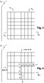
- the image IC j thus partitioned is represented at picture 3 .
- the image IC j is partitioned into four blocks B 1 , B 2 , B 3 and B 4 .
- block means coding unit.
- This latter terminology is notably used in the HEVC standard, for example in the document “ B. Bross, W.-J. Han, J.-R. Ohm, GJ Sullivan, and T. Wiegand, "High efficiency video coding (HEVC) text specification draft 10," document JCTVC-L1003 of JCT-VC, Geneva, CH, 14-23 January 2013 ".
- such a coding unit groups together sets of pixels of rectangular or square shape, also called blocks, macroblocks, or else sets of pixels having other geometric shapes.
- Said blocks B 1 , B 2 , ..., B u , ..., B S are intended to be coded according to a predetermined traversal order, which is for example of the raster scan type. This means that the blocks are coded one after the other, from left to right.
- the blocks B 1 , B 2 , B 3 and B 4 have a square shape and all have the same size.
- the last blocks on the left and the last blocks at the bottom may not be square.
- the blocks may for example be rectangular in size and/or not aligned with each other.
- Each block can moreover itself be divided into sub-blocks which are themselves subdividable.
- the coder CO selects as current block a first block to be coded B u of the image IC j , such as for example the first block B 1 .
- the current block B u is predicted by known intra and/or inter prediction techniques.
- the block B u is predicted with respect to at least one predictor block in accordance with a prediction mode selected from among a plurality of predetermined prediction modes MP 0 , MP 1 ,..., MP v ,..., MP Q where 0 ⁇ v ⁇ Q+1.
- the predetermined prediction modes are of the intra type and Q is equal to 4.
- Such a predictor block is for example a block of pixels which has already been coded or else coded then decoded or not.
- Such a predictor block is stored beforehand in the buffer memory MT_CO of the coder CO as shown in picture 2 .
- an optimal predictor block BP opt is obtained following a competition between said predetermined prediction modes, for example by minimizing a bitrate distortion criterion well known to those skilled in the art. .
- the block BP opt is considered as an approximation of the current block B u .
- the information relating to this prediction is intended to be written into a signal or data stream to be transmitted to a decoder. Such information includes in particular the type of prediction (inter or intra), and if applicable, the mode of prediction selected, the type of partitioning of the current block if the latter has been subdivided, the reference image index and the displacement vector used in the case where an inter prediction mode has been selected. This information is compressed by the CO encoder.
- the data relating to the current block B u are compared with the data of the predictor block BP opt . More specifically, during this step, the difference between the obtained predictor block BP opt and the current block B u is conventionally calculated.
- a set of residual data, called residual block Br u is then obtained at the end of step C4.
- Steps C3 and C4 are implemented by a predictive coding software module PRED1_CO represented on the picture 2 , which module is controlled by the microprocessor ⁇ P of the processing unit UT_CO.
- the residue block Br u is transformed according to a conventional direct transformation operation such as for example a discrete cosine transformation of the DCT type or a wavelet transformation of the DWT type, to produce a transformed block Bt u .
- a transform software module MT_CO as represented picture 2 , which module is controlled by the microprocessor ⁇ P of the processing unit UT_CO.
- the transformed block Bt u is quantized according to a conventional quantization operation, such as for example scalar or vector quantization.
- a block Bq u of NxN quantized coefficients is then obtained, where N is an integer greater than or equal to 1.
- Such a step is performed by means of a quantization software module MQ_CO as represented in picture 2 , which module is controlled by the microprocessor ⁇ P of the processing unit UT_CO.
- the quantized coefficients of the block Bq u are scanned in a predefined order. In the example shown, it is a conventional zigzag path, in increasing order of frequency.
- a reading software module ML_CO as shown in figure 2 , which module is controlled by the microprocessor ⁇ P of the processing unit UT_CO.
- Such an entropy coding step is implemented by an entropy coding software module MCE represented on the picture 2 , which module is controlled by the microprocessor ⁇ P of the processing unit UT_CO.
- the entropic coding module MCE is for example of the CABAC (“Context Adaptive Binary Arithmetic Coder”) type. It may also be a Huffman coder known as such.
- At least one coefficient ⁇ i of the one-dimensional vector RQ u having a non-zero amplitude and a + or - sign is selected.
- such a selection is advantageously implemented using a predetermined criterion which is a function of the prediction mode selected in the prediction step C3.
- Such a selection step is carried out by a selection software module SEL_CO, as shown in figure 2 , which module is controlled by the microprocessor ⁇ P of the processing unit UT_CO.
- said predetermined selection criterion consists of a table TA recorded in a memory (not shown) of the coder C0 which associates with each of said predetermined prediction modes an ordered list of the coefficients of the one-dimensional vector RQ u , the order of the coefficients of a list being variable from one prediction mode to another.
- the coefficients ⁇ 0 , ⁇ 1 ,..., ⁇ i ,..., ⁇ N 2 -1 are sixteen in number and there are five predetermined prediction modes MP 0 , MP 1 , MP 2 , MP3 , MP4 .
- the table TA is then presented in the following form:
- the row which corresponds to the prediction mode which was used to predict the current block B u is selected from the table TA. For example, if it is the MP 3 prediction mode, the row of coefficient indices corresponding to this mode of prediction is selected.
- the coefficients ⁇ 0 to ⁇ 15 are then traversed in the order given by the line of coefficient indices selected, i.e. respectively 12, 13, 14, 15, 0, 1, 2, 3, 4, 5, 6, 7 , 8, 9, 10, 11.
- an order by increasing or decreasing non-zero amplitude of the coefficients of the one-dimensional vector RQ u is selected according to the predetermined prediction mode which has been selected to predict the current block B u .
- selection criteria are in no way limiting, from the moment the criterion takes account of the prediction mode selected in the prediction step C3, to identify the coefficients whose sign will be the most predictable.
- step C10 shown in figure 1 the coding of the signs of the coefficients of the one-dimensional vector RQ u whose indices have not been retained in the list L is carried out in a conventional manner.
- Such a coding step is performed by a sign coding software module MCS_CO, as shown in picture 2 , which module is controlled by the microprocessor ⁇ P of the processing unit UT_CO.
- the signs +, -, +, -, + corresponding respectively to the coefficients ⁇ 0 , ⁇ 2 , ⁇ 6 , ⁇ 7 , ⁇ 9 are then coded in a manner known per se.
- the sign + is coded by a bit at zero
- the sign - is coded by a bit at one.
- Such a sign prediction step is performed by a sign prediction software module PRED2_CO, as shown in picture 2 , which module is controlled by the microprocessor ⁇ P of the processing unit UT_CO.
- Each of these four residual blocks are decoded so as to respectively obtain four decoded residual blocks BDr u0 , BDr u1 , BDr u2 , BDr u3 .
- the predictor block BP opt obtained in the aforementioned prediction step C3 is added to each of these four decoded residual blocks, which makes it possible to obtain four decoded blocks BDu 0 , BD u1 , BD u2 , u3 comics.
- these four blocks decoded only one is the real decoded block resulting from the coding of the current block Bu.
- a plausibility test is then carried out for each of the decoded blocks BDu 0 , BD u1 ,..., BD ud ,..., BD uW-1 , with a plausibility criterion, where 0 ⁇ d ⁇ W .
- the plausibility test consists in applying a criterion for minimizing the difference between the decoded pixels of the current image IC j , which are represented by points on the figure 4 , and the pixels of each decoded block BDu 0 , BD u1 ,..., BD ud ,..., BDu W-1 along their respective boundary F represented by hatching on the figure 4 .
- This criterion is a mathematical operator denoted SM(BD ud , IC j ).
- the operator SM(BD ud , IC j ) is representative of the quadratic error along the boundary F of the decoded residual block BDr u with the image IC j .
- a simplified criterion can be used, where the mean of the pixels of the image IC j along the border F is compared with the mean of the pixels of the decoded block BD ud .
- the decoded residual block is identified, among the decoded residual blocks BDr u0 , BDr u1 , ..., BDr uW-1 , which is associated with the decoded block BD udmin .
- the signs associated with the coefficients whose indices I 0 to I K -1 are contained in the list L are then considered as the predicted values of the signs of the coefficients of said residual block associated with the identified decoded residual block.
- Such a calculation step is carried out by a calculation software module CAL_CO, as shown in picture 2 , which module is controlled by the microprocessor ⁇ P of the processing unit UT_CO.
- the prediction of the signs is false since the predicted values of sign Sp 1 and Sp 2 are respectively ⁇ +,+ ⁇ while the values of the signs of the coefficients ⁇ 14 and ⁇ 15 are respectively ⁇ -,+ ⁇ . Consequently, the indicator Id takes the binary values 01 to indicate that the prediction of the sign of the coefficient ⁇ 14 is false and that the prediction of the sign of the coefficient ⁇ 15 is exact.
- Such a calculation step is carried out by an information coding software module MCI_CO, as shown in figure 2 , which module is controlled by the microprocessor ⁇ P of the processing unit UT_CO.
- a signal or data stream ⁇ which contains all of the encoded data of the block of quantized coefficients Bq u and the encoded identifier Id is then delivered. Such a stream is then transmitted by a communication network (not shown), to a remote terminal. This includes the DO decoder shown in figure 5 .
- the stream ⁇ further comprises certain information encoded by the coder CO, such as the type of prediction (inter or intra), and if applicable, the prediction mode selected, the type of partitioning of the block if the latter has been partitioned, the reference image index and the displacement vector used in the inter prediction mode.
- step C14 the block Bq u is dequantized according to a conventional dequantization operation, which is the inverse operation of the quantization carried out in step C6.
- a block of dequantized coefficients BDq u is then obtained.
- Such a dequantization step is performed by an inverse quantization software module MT -1 _CO, as shown in picture 2 , which module is controlled by the microprocessor ⁇ P of the processing unit UT_CO.
- step C15 the inverse transformation of the block of dequantized coefficients BDq u is carried out, which is the inverse operation of the direct transformation carried out in step C5 above.
- a decoded residual block BDr u is then obtained.
- Such an operation is performed by an inverse transform software module MT -1 _CO, as represented picture 2 , which module is controlled by the microprocessor ⁇ P of the processing unit UT_CO.
- the decoded block BD u is constructed by adding to the predictor block BP opt obtained in the aforementioned step C3 the decoded residue block BDr u . It should be noted that this last block is the same as the decoded block obtained at the end of the process for decoding the image IC j which will be described later in the description.
- the decoded block BD u is then stored in the buffer memory MT_CO of the figure 2 , in order to be used by the coder CO as a predictor block of a following block to be coded.
- Such a step is implemented by an inverse predictive coding software module PRED -1 _CO represented on the picture 2 , which module is controlled by the microprocessor ⁇ P of the processing unit UT_CO.
- the coder CO tests whether the current block B u which has just been coded is the last block of the image IC j .
- the coding process is terminated.
- step C2 of selecting the next block to be coded is again carried out in accordance with the aforementioned raster scan traversal order, then the steps C3 to C17 are repeated for this next block selected .
- decoding method is implemented in software or hardware by modifications of a decoder initially conforming to the HEVC standard.
- the decoding method according to the invention is represented in the form of an algorithm comprising steps D1 to D15 as represented in figure 6 .
- the DO decoder comprises a memory MEM_DO comprising a buffer memory MT_DO, a processing unit UT_DO equipped for example with a microprocessor ⁇ P and controlled by a computer program PG_DO which implements the decoding method according to the invention.
- the code instructions of the computer program PG_DO are for example loaded into a RAM memory before being executed by the processor of the processing unit UT_DO.
- the decoding process represented on the figure 6 applies to any current image of a sequence SQ of images to be decoded.
- information representative of the current image IC j to be decoded is identified in a signal or data stream ⁇ received at the decoder, as delivered following the method of encoding the figure 1 .
- Such an identification step is implemented by a flow analysis identification module MI_DO, as shown in figure 5 , said module being controlled by the microprocessor ⁇ P of the processing unit UT_DO.
- Said quantized residues RQ 1 , RQ 2 , ..., RQ u ,..., RQs are intended to be decoded according to a predetermined traversal order, which is for example sequential, that is to say that said residues are intended to be decoded one after the other according to the raster scan order in which they were encoded.
- the blocks to be decoded have a square shape and all have the same size.
- the last blocks on the left and the last blocks at the bottom may not be square.
- the blocks may for example be rectangular in size and/or not aligned with each other.
- Each block can moreover itself be divided into sub-blocks which are themselves subdividable.
- the current block B u to be decoded is predicted by known intra and/or inter prediction techniques.
- the block B u to be decoded is predicted with respect to at least one predictor block in accordance with a prediction mode selected from among a plurality of predetermined prediction modes MP 0 , MP 1 ,..., MP v ,.. ., MP Q where 0 ⁇ v ⁇ Q+1.
- the predetermined prediction modes are of the intra type and Q is equal to 4.
- the selected prediction mode is directly read in the stream ⁇ in the case where the coder CO of the figure 2 signaled this mode to the DO decoder of the figure 5 .
- the prediction mode is selected at the decoder DO by placing said predetermined prediction modes in competition, for example by minimizing a bitrate distortion criterion well known to those skilled in the art.
- Such a predictor block is for example a block of pixels which has already been decoded or not.
- Such a predictor block is stored beforehand in the buffer memory MT_DO of the decoder DO as shown in figure 5 .
- an optimal predictor block BP opt conforming to the selected prediction mode is obtained.
- the BP opt block is a approximation of the current block B u to be decoded.
- the information relating to this prediction is read from the data stream ⁇ . Such information includes in particular the type of prediction (inter or intra), the type of partitioning of the current block if the latter has been subdivided, the reference image index and the displacement vector used in the case where a mode of inter prediction has been selected. This information will subsequently be decoded in a conventional manner.
- Step D3 is implemented by a predictive decoding software module PRED1_DO represented on the figure 5 , which module is controlled by the microprocessor ⁇ P of the processing unit UT_DO.
- Such an entropy decoding step is implemented by an entropy decoding software module MDE represented on the figure 5 , which module is controlled by the microprocessor ⁇ P of the processing unit UT_DO.
- the entropy decoding module MDE is for example of the CABAC type. It may also be a Huffman decoder known as such.
- At least one coefficient of the one-dimensional vector RQ u having a non-zero amplitude and a + or - sign is selected.
- such a selection is advantageously implemented using a predetermined criterion which is a function of the prediction mode selected in the prediction step D3.
- the selection step D5 is in all respects identical to the selection step C9 carried out during the coding with reference to the figure 1 .
- Such a selection step is performed by a selection software module SEL_DO, as shown in figure 5 , which module is controlled by the microprocessor ⁇ P of the processing unit UT_DO.
- said predetermined selection criterion consists of a table TA stored in a memory (not shown) of the decoder DO which associates with each of said predetermined prediction modes an ordered list of the coefficients of the one-dimensional vector RQ u , the order of the coefficients of a list being variable from one prediction mode to another.
- the coefficients ⁇ 0 , ⁇ 1 ,..., ⁇ i ,..., ⁇ N 2 -1 are sixteen in number and there are five predetermined prediction modes MP 0 , MP 1 , MP 2 , MP3 , MP4 .
- the table TA is then presented in the following form:
- the line which corresponds to the prediction mode which was used to predict the current block B u to be decoded is chosen from the table TA. For example, if it is the prediction mode MP 3 , the line of coefficient indices corresponding to this prediction mode is selected. The coefficients ⁇ 0 to ⁇ 15 are then traversed in the order given by the line of coefficient indices selected, i.e. respectively 12, 13, 14, 15, 0, 1, 2, 3, 4, 5, 6, 7 , 8, 9, 10, 11.
- a list L ⁇ I 0 , I 1 ,..., I z ,..., I K-1 ⁇ (0 ⁇ z ⁇ K) containing the indices of K coefficients identified in said subset, is then constructed .
- L ⁇ 14,15 ⁇ .
- an order by increasing or decreasing non-zero amplitude of the coefficients of the one-dimensional vector RQ u is selected according to the predetermined prediction mode which has been selected to predict the current block B u to be decoded.
- selection criteria are in no way limiting, from the moment the criterion takes account of the prediction mode selected in the prediction step D3, to identify the coefficients whose sign will be the most predictable.
- a list L ⁇ I 0 , I 1 ,..., I z ,..., I K-1 ⁇ (0 ⁇ z ⁇ K) containing the indices of K coefficients of the one-dimensional vector RQ u .
- the conventional way is to decode the signs of the coefficients of the one-dimensional vector RQ u whose indices have not been retained in the list L.
- Such a decoding step is carried out by a sign decoding software module MDS_DO as shown in figure 5 , which module is controlled by the microprocessor ⁇ P of the processing unit UT_DO.
- the signs +, -, +, -, + corresponding respectively to the coefficients ⁇ 0 , ⁇ 2 , ⁇ 6 , ⁇ 7 , ⁇ 9 are then decoded.
- the + sign is reconstructed by reading in the stream ⁇ from one bit to zero, while the - sign is reconstructed by reading in the stream ⁇ from one bit to one.
- Such a sign prediction step is performed by a sign prediction software module PRED2_DO as shown in figure 5 , which module is controlled by the microprocessor ⁇ P of the processing unit UT_DO.
- Said sign prediction step D7 is in all respects identical to the sign prediction step C11 carried out during the coding with reference to the figure 1 .
- Each of these four residual blocks are decoded so as to respectively obtain four decoded residual blocks BDr u0 , BDr u1 , BDr u2 , BDr u3 .
- the predictor block BP opt obtained in the aforementioned prediction step D3 is added to each of these four decoded residual blocks, which makes it possible to obtain four decoded blocks BDu 0 , BD u1 , BD u2 , u3 comics.
- these four decoded blocks only one is the real decoded block as obtained after the decoding of the current block B u to be decoded.
- a plausibility test is then carried out for each of the decoded blocks BDu 0 , BD u1 ,..., BD ud ,..., BD uW-1 , with a plausibility criterion.
- the plausibility test consists in applying a criterion for minimizing the difference between the decoded pixels of the current image IC j , which are represented by points on the figure 4 , and the pixels of each decoded block BDu 0 , BD u1 ,..., BD ud ,..., BD uW-1 along their respective boundary F represented by hatching on the figure 4 .
- This criterion is a mathematical operator denoted SM(BD ud , IC j ).
- the operator SM(BD ud , IC j ) is representative of the quadratic error along the boundary F of the decoded residual block BDr u with the image IC j .
- a simplified criterion can be used, where the mean of the pixels of the image IC j along the border F is compared with the mean of the pixels of the decoded block BD ud .
- the decoded residual block is identified, among the decoded residual blocks BDr u0 , BDr u1 , ..., BDr uW-1 , which is associated with the decoded block BD udmin .
- the signs associated with the coefficients whose indices I 0 to I K -1 are contained in the list L are then considered as the predicted values of the signs of the coefficients of said residual block associated with the identified decoded residual block.
- Such a reading step is performed by a reading software module ML_DO as shown in figure 5 , which module is controlled by the microprocessor ⁇ P of the processing unit UT_DO.
- the prediction of the signs is false since the predicted values of sign Sp 1 and Sp 2 are respectively ⁇ +,+ ⁇ while the values of the signs of the coefficients ⁇ 14 and ⁇ 15 are respectively ⁇ -,+ ⁇ . Consequently, the read information Id is “01” to indicate that the prediction of the sign of the coefficient ⁇ 14 is false and that the prediction of the sign of the coefficient ⁇ 15 is correct.
- Such a sign decoding step is carried out by a calculation software module CAL_DO as shown in figure 5 , which module is controlled by the microprocessor ⁇ P of the processing unit UT_DO.
- step D10 the quantified residue RQ u is dequantized according to a conventional dequantization operation, which is in all respects identical to the dequantization step carried out in step C14 of the figure 1 .
- a decoded dequantized block BDt u is then obtained.
- Such a dequantization step is performed by an inverse quantization software module MQ -1 _DO as shown in figure 5 , which module is controlled by the microprocessor ⁇ P of the processing unit UT_DO.
- step D11 the inverse transformation of the block of dequantized coefficients BDt u is carried out, which is in all respects identical to the inverse transformation step carried out in step C15 of the figure 1 .
- a decoded residual block BDr u is then obtained.
- Such an operation is performed by an inverse transform software module MT -1 _DO, as represented figure 5 , which module is controlled by the microprocessor ⁇ P of the processing unit UT_DO.
- step D12 the current block B u is reconstructed by adding to the decoded current residual block BDr u the predictor block BP opt obtained in step D3.
- Said step D12 is implemented by an inverse prediction software module PRED -1 _DO represented on the figure 5 , which module is controlled by the microprocessor ⁇ P of the processing unit UT_DO.
- a decoded block BD u is then obtained and stored in the buffer memory MT_DO of the figure 5 , in order to be used by the decoder DO as a predictor block of a following block to be decoded.
- step D13 said decoded block BD u is written in a decoded image ID j .
- One such step is implementing an image reconstruction URI software module as shown in Fig. figure 5 , said module being controlled by the microprocessor ⁇ P of the processing module UT_DO.
- the decoder DO tests whether the current block BD u which has just been decoded is the last block contained in the stream ⁇ .
- next residual block to be decoded is selected during step D2 in accordance with the aforementioned raster scan traversal order.
Description
La présente invention se rapporte de manière générale au domaine du traitement d'images, et plus précisément au codage et au décodage d'images numériques et de séquences d'images numériques.The present invention relates generally to the field of image processing, and more specifically to the coding and decoding of digital images and sequences of digital images.
Le codage/décodage d'images numériques s'applique notamment à des images issues d'au moins une séquence vidéo comprenant :
- des images issues d'une même caméra et se succédant temporellement (codage/décodage de type 2D),
- des images issues de différentes caméras orientées selon des vues différentes (codage/décodage de type 3D),
- des composantes de texture et de profondeur correspondantes (codage/décodage de type 3D),
- etc...
- images from the same camera and temporally succeeding each other (2D type coding/decoding),
- images from different cameras oriented according to different views (3D type coding/decoding),
- corresponding texture and depth components (3D type coding/decoding),
- etc...
La présente invention s'applique de manière similaire au codage/décodage d'images de type 2D ou 3D.The present invention applies similarly to the coding/decoding of 2D or 3D type images.
L'invention peut notamment, mais non exclusivement, s'appliquer au codage vidéo mis en œuvre dans les codeurs vidéo actuels AVC et HEVC et leurs extensions (MVC, 3D-AVC, MV-HEVC, 3D-HEVC, etc), et au décodage correspondant.The invention can in particular, but not exclusively, be applied to the video coding implemented in the current AVC and HEVC video coders and their extensions (MVC, 3D-AVC, MV-HEVC, 3D-HEVC, etc.), and to the corresponding decoding.
Les codeurs vidéo actuels (MPEG, H.264, HEVC, ...) utilisent une représentation par blocs de la séquence vidéo. Les images sont découpées en blocs, lesquels sont susceptibles d'être redécoupés de façon récursive. Puis chaque bloc est codé par prédiction intra-images ou inter-images. Ainsi, certaines images sont codées par prédiction spatiale (prédiction intra), tandis que d'autres images sont codées par prédiction temporelle (prédiction inter) par rapport à une ou plusieurs images de référence codées-décodées, à l'aide d'une compensation en mouvement connue par l'homme de l'art.Current video coders (MPEG, H.264, HEVC, etc.) use a block representation of the video sequence. The images are cut into blocks, which are likely to be recut recursively. Then each block is coded by intra-image or inter-image prediction. Thus, certain images are coded by spatial prediction (intra prediction), while other images are coded by temporal prediction (inter prediction) with respect to one or more coded-decoded reference images, using a compensation moving known to those skilled in the art.
Pour chaque bloc est codé un bloc résiduel, encore appelé résidu de prédiction, correspondant au bloc original diminué d'une prédiction. Les blocs résiduels sont transformés par une transformée par exemple de type transformée en cosinus discrète (DCT), puis quantifiés à l'aide d'une quantification par exemple de type scalaire. Des coefficients, dont certains sont positifs et d'autres négatifs, sont obtenus à l'issue de l'étape de quantification. Ils sont ensuite parcourus dans un ordre de lecture généralement en zigzag (comme dans la norme JPEG), ce qui permet d'exploiter le nombre important de coefficients nuls dans les hautes fréquences. A l'issue du parcours précité, une liste monodimensionnelle de coefficients est obtenue, laquelle sera appelée « résidu quantifié ». Les coefficients de cette liste sont alors codés par un codage entropique.For each block is coded a residual block, also called residual of prediction, corresponding to the original block minus a prediction. The residual blocks are transformed by a transform, for example of the discrete cosine transform (DCT) type, then quantized using a quantization, for example of the scalar type. Coefficients, some of which are positive and others negative, are obtained at the end of the quantification step. They are then traversed in a reading order generally in zigzag (as in the JPEG standard), which makes it possible to exploit the large number of zero coefficients in the high frequencies. At the end of the aforementioned route, a one-dimensional list of coefficients is obtained, which will be called “quantified residue”. The coefficients of this list are then coded by an entropy coding.
Le codage entropique (par exemple de type codage arithmétique ou codage de Huffman) est effectué de la façon suivante :
- une information est codée entropiquement pour indiquer l'emplacement du dernier coefficient non nul de la liste,
- pour chaque coefficient situé avant le dernier coefficient non nul, une information est codée entropiquement pour indiquer si le coefficient est nul ou pas,
- pour chaque coefficient non nul indiqué précédemment, une information est codée entropiquement pour indiquer si le coefficient est égal à un ou pas,
- pour chaque coefficient non nul et non égal à un situé avant le dernier coefficient non nul, une information d'amplitude (valeur absolue du coefficient diminuée de deux) est codée entropiquement.
- information is entropically coded to indicate the location of the last non-zero coefficient in the list,
- for each coefficient located before the last non-zero coefficient, information is entropically coded to indicate whether the coefficient is zero or not,
- for each non-zero coefficient indicated previously, information is entropically coded to indicate whether the coefficient is equal to one or not,
- for each non-zero coefficient and not equal to one located before the last non-zero coefficient, amplitude information (absolute value of the coefficient reduced by two) is entropically coded.
Ainsi, l'amplitude de chaque coefficient est codée en tenant compte de la probabilité d'apparition de ces coefficients dans le bloc courant à coder.Thus, the amplitude of each coefficient is coded taking into account the probability of appearance of these coefficients in the current block to be coded.
En revanche, les signes qui affectent les coefficients non nuls ne sont pas codés entropiquement mais codés respectivement par un bit égal à '0' (par exemple pour le signe +) ou par un bit égal à '1' (par exemple pour le signe -). Ces bits sont inscrits dans un signal ou flux de données qui est destiné à être transmis au décodeur.On the other hand, the signs which affect the non-zero coefficients are not entropically coded but coded respectively by a bit equal to '0' (for example for the sign +) or by a bit equal to '1' (for example for the sign -). These bits are inscribed in a signal or data stream which is intended to be transmitted to the decoder.
De façon connue en soi, un tel signal comprend :
- les résidus quantifiés contenus dans la liste précitée,
- des informations représentatives du mode de codage utilisé, en particulier:
- le mode de prédiction (prédiction intra, prédiction inter, prédiction par défaut réalisant une prédiction pour laquelle aucune information n'est transmise au décodeur (« en anglais « skip »)) ;
- des informations précisant le type de prédiction (orientation, image de référence, ...) ;
- le type de découpage du bloc ;
- le type de transformée, par exemple DCT 4x4, DCT 8x8, etc...
- les informations de mouvement si nécessaire ;
- etc.
- the quantified residues contained in the aforementioned list,
- information representative of the coding mode used, in particular:
- the prediction mode (intra prediction, inter prediction, default prediction performing a prediction for which no information is transmitted to the decoder (“skip” in English);
- information specifying the type of prediction (orientation, reference image, etc.);
- the type of splitting of the block;
- the type of transform, for example DCT 4x4, DCT 8x8, etc...
- movement information if necessary;
- etc
Compte tenu des nombreuses informations à signaler dans le flux, il en résulte que l'ajout systématique d'un bit de signe dans le flux à transmettre au décodeur est coûteuse en débit et nuit aux performances de compression du signal.Given the large amount of information to be signaled in the stream, the result is that the systematic addition of a sign bit in the stream to be transmitted to the decoder is expensive in terms of bit rate and harms the signal compression performance.
Une fois que le flux a été reçu par le décodeur, le décodage est fait image par image, et pour chaque image, bloc par bloc. Pour chaque bloc, les éléments correspondants du flux sont lus. La quantification inverse et la transformation inverse des coefficients des blocs sont effectuées pour produire le résidu de prédiction décodé. Puis, la prédiction du bloc est calculée et la bloc est reconstruit en ajoutant la prédiction au résidu de prédiction décodé.Once the stream has been received by the decoder, the decoding is done image by image, and for each image, block by block. For each block, the corresponding elements of the stream are read. Inverse quantization and inverse transformation of the block coefficients are performed to produce the decoded prediction residual. Then, the prediction of the block is calculated and the block is reconstructed by adding the prediction to the decoded prediction residual.
Le document «
Une telle prédiction améliore, certes, les performances de compression du signal de données codées. Toutefois, le coefficient dont le signe est prédit ne résulte pas nécessairement d'un choix optimal, de sorte que la prédiction de signe appliquée est susceptible d'entraîner des perturbations dans le signal transmis au décodeur. De telles perturbations nuisent inévitablement à l'efficacité de la compression vidéo.Such a prediction certainly improves compression performance of the encoded data signal. However, the coefficient whose sign is predicted does not necessarily result from an optimal choice, such that the sign prediction applied is liable to cause disturbances in the signal transmitted to the decoder. Such disturbances inevitably affect the efficiency of video compression.
Un des buts de l'invention est de remédier à des inconvénients de l'état de la technique précité.One of the aims of the invention is to remedy the drawbacks of the aforementioned state of the art.
A cet effet, un objet de la présente invention concerne un procédé de codage d'au moins une image découpée en blocs, selon la revendication 1 et représenté sur la
- prédiction du bloc courant conformément à un mode de prédiction sélectionné parmi une pluralité de modes de prédiction prédéterminés,
- obtention d'un bloc prédicteur,
- détermination d'un ensemble de données résiduelles représentatif de la différence entre le bloc prédicteur obtenu et le bloc courant, les données résiduelles étant susceptibles d'avoir une amplitude et un signe.
- prediction of the current block in accordance with a prediction mode selected from among a plurality of predetermined prediction modes,
- obtaining a predictor block,
- determination of a set of residual data representative of the difference between the predictor block obtained and the current block, the residual data being likely to have an amplitude and a sign.
Le procédé de codage selon l'invention est remarquable en ce qu'il met en œuvre les étapes suivantes :
- sélection, dans l'ensemble de données résiduelles, d'au moins une donnée résiduelle affectée d'une amplitude et d'un signe, à l'aide d'un critère prédéterminé qui est fonction du mode de prédiction sélectionné,
- obtention d'une valeur prédite du signe de ladite au moins une donnée résiduelle sélectionnée,
- calcul d'une information représentative de la différence entre la valeur prédite du signe et la valeur du signe de ladite au moins une donnée résiduelle sélectionnée,
- codage de l'information calculée.
- selection, from the set of residual data, of at least one residual datum assigned an amplitude and a sign, using a predetermined criterion which is a function of the selected prediction mode,
- obtaining a predicted value of the sign of said at least one selected residual datum,
- calculation of information representative of the difference between the predicted value of the sign and the value of the sign of said at least one selected residual datum,
- coding of the calculated information.
Une telle disposition a pour avantage de tenir compte du mode de prédiction du bloc courant pour prédire le signe d'une ou de plusieurs données résiduelles, ce qui permet d'identifier la ou les données résiduelles dont le signe est le plus prédictible. Une telle identification étant plus fiable que dans l'art antérieur précité, elle permet d'obtenir de meilleures performances de compression du signal de données à transmettre au décodeur, et au final, une meilleure qualité de reconstruction de l'image au décodeur.Such an arrangement has the advantage of taking into account the prediction mode of the current block to predict the sign of one or more residual data, which makes it possible to identify the residual data or data whose sign is the most predictable. Such identification being more reliable than in the art aforementioned prior art, it makes it possible to obtain better compression performance of the data signal to be transmitted to the decoder, and in the end, a better quality of reconstruction of the image at the decoder.
Selon un mode de réalisation particulier, l'étape d'obtention de la valeur prédite du signe de ladite au moins une donnée résiduelle sélectionnée est fonction de pixels précédemment codés puis décodés de l'image courante qui sont situés le long du bloc courant.According to a particular embodiment, the step of obtaining the predicted value of the sign of said at least one residual datum selected is a function of previously coded then decoded pixels of the current image which are situated along the current block.
Une telle disposition permet ainsi de minimiser les discontinuités susceptibles d'apparaître le long des frontières du bloc courant, tout en correspondant mieux à la réalité de l'image.Such an arrangement thus makes it possible to minimize the discontinuities likely to appear along the borders of the current block, while corresponding better to the reality of the image.
Selon un autre mode de réalisation particulier, le critère prédéterminé pour sélectionner ladite au moins une donnée résiduelle consiste en une table qui associe à chacun des modes de prédiction prédéterminés une liste ordonnée des données résiduelles, l'ordre des données résiduelles d'une liste étant variable d'un mode de prédiction à l'autre.According to another particular embodiment, the predetermined criterion for selecting said at least one residual datum consists of a table which associates with each of the predetermined prediction modes an ordered list of residual data, the order of the residual data of a list being variable from one prediction mode to another.
Une telle disposition permet, pour un mode de prédiction considéré, de sélectionner facilement et précisément le ou les coefficients dont le signe correspondant est le plus prédictible, sans que la prédiction de ces signes n'entraîne de perturbations élevées dans le signal à transmettre au décodeur.Such an arrangement makes it possible, for a considered prediction mode, to easily and precisely select the coefficient or coefficients whose corresponding sign is the most predictable, without the prediction of these signs leading to high disturbances in the signal to be transmitted to the decoder. .
Il en résulte une augmentation des performances de compression du codeur tout en réduisant efficacement le coût de signalisation.This results in an increase in encoder compression performance while effectively reducing signaling cost.
Les différents modes ou caractéristiques de réalisation précités peuvent être ajoutés indépendamment ou en combinaison les uns avec les autres, aux étapes du procédé de codage tel que défini ci-dessus.The various aforementioned embodiments or characteristics can be added independently or in combination with each other, to the steps of the coding method as defined above.
L'invention concerne également un dispositif de codage d'au moins une image découpée en blocs, selon la revendication 4, et comprenant notamment, pour un bloc courant à coder :
- un module de prédiction du bloc courant conformément à un mode de prédiction sélectionné parmi une pluralité de modes de prédiction prédéterminés,
- un module de détermination d'un ensemble de données résiduelles représentatif de la différence entre un bloc prédicteur, obtenu suite à l'activation du module de prédiction, et le bloc courant, les données résiduelles étant susceptibles d'avoir une amplitude et un signe.
- a current block prediction module in accordance with a prediction mode selected from among a plurality of predetermined prediction modes,
- a module for determining a set of residual data representative of the difference between a predictor block, obtained following activation of the prediction module, and the current block, the residual data being likely to have an amplitude and a sign.
Un tel dispositif de codage est remarquable en ce qu'il comprend en outre :
- un module de sélection, dans l'ensemble de données résiduelles, d'au moins une donnée résiduelle affectée d'une amplitude et d'un signe, à l'aide d'un critère prédéterminé qui est fonction du mode de prédiction sélectionné,
- un module d'obtention d'une valeur prédite du signe de ladite au moins une donnée résiduelle sélectionnée,
- un module de calcul d'une information représentative de la différence entre la valeur prédite du signe et la valeur du signe de ladite au moins une donnée résiduelle sélectionnée,
- un module de codage de l'information calculée.
- a module for selecting, from the set of residual data, at least one residual datum assigned an amplitude and a sign, using a predetermined criterion which is a function of the prediction mode selected,
- a module for obtaining a predicted value of the sign of said at least one selected residual datum,
- a module for calculating information representative of the difference between the predicted value of the sign and the value of the sign of said at least one selected residual datum,
- a calculated information coding module.
Un tel dispositif de codage est apte à mettre en œuvre le procédé de codage précité.Such a coding device is capable of implementing the aforementioned coding method.
De façon correspondante, l'invention concerne aussi un procédé de décodage d'un signal de données représentatif d'au moins une image découpée en blocs, selon la revendication 7 et représenté sur la
- détermination, dans le signal de données, d'un ensemble de données résiduelles relatif au bloc courant, au moins une donnée résiduelle de l'ensemble précité étant affectée d'une amplitude et d'un signe,
- prédiction du bloc courant conformément à un mode de prédiction sélectionné parmi une pluralité de modes de prédiction prédéterminés.
- determination, in the data signal, of a set of residual data relating to the current block, at least one residual datum of the aforementioned set being assigned an amplitude and a sign,
- predicting the current block according to a prediction mode selected from a plurality of predetermined prediction modes.
Un tel procédé de décodage est remarquable en ce qu'il met en œuvre les étapes suivantes :
- sélection, dans l'ensemble de données résiduelles, d'au moins une donnée résiduelle affectée d'une amplitude et d'un signe, à l'aide d'un critère prédéterminé qui est fonction du mode de prédiction déterminé,
- obtention d'une valeur prédite du signe de ladite au moins une donnée résiduelle sélectionnée,
- détermination, dans le signal de données, d'une information représentative de la différence entre la valeur prédite du signe et la valeur du signe de ladite au moins une donnée résiduelle sélectionnée,
- reconstruction du signe à l'aide de la valeur prédite du signe et de l'information représentative déterminée.
- selection, from the set of residual data, of at least one residual datum affected by an amplitude and a sign, using a predetermined criterion which is a function of the determined prediction mode,
- obtaining a predicted value of the sign of said at least one selected residual datum,
- determination, in the data signal, of information representative of the difference between the predicted value of the sign and the value of the sign of said at least one selected residual datum,
- reconstruction of the sign using the predicted value of the sign and the determined representative information.
Selon un mode de réalisation particulier, l'étape d'obtention de la valeur prédite du signe de ladite au moins une donnée résiduelle sélectionnée est fonction de pixels précédemment décodés de l'image courante qui sont situés le long du bloc courant.According to a particular embodiment, the step of obtaining the predicted value of the sign of said at least one residual datum selected is a function of previously decoded pixels of the current image which are located along the current block.
Selon un autre mode de réalisation particulier, le critère prédéterminé pour sélectionner ladite au moins une donnée résiduelle consiste en une table qui associe à un mode de prédiction déterminé une liste ordonnée des données résiduelles, l'ordre des données résiduelles d'une liste étant variable d'un mode de prédiction à l'autre.According to another particular embodiment, the predetermined criterion for selecting said at least one residual datum consists of a table which associates with a given prediction mode an ordered list of residual data, the order of the residual data of a list being variable from one prediction mode to another.
Les différents modes ou caractéristiques de réalisation précités peuvent être ajoutés indépendamment ou en combinaison les uns avec les autres, aux étapes du procédé de décodage tel que défini ci-dessus.The various aforementioned embodiments or characteristics can be added independently or in combination with each other, to the steps of the decoding method as defined above.
Corrélativement, l'invention concerne encore un dispositif de décodage d'un signal d'un signal de données représentatif d'au moins une image découpée en blocs, selon la revendication 10, et comprenant notamment, pour un bloc courant à décoder :
- un module de détermination, dans le signal de données, d'un ensemble de données résiduelles relatif au bloc courant, au moins une donnée résiduelle de l'ensemble précité étant affectée d'une amplitude et d'un signe,
- un module de prédiction du bloc courant conformément à un mode de prédiction sélectionné parmi une pluralité de modes de prédiction prédéterminés.
- a module for determining, in the data signal, a set of residual data relating to the current block, at least one residual datum of the aforementioned set being assigned an amplitude and a sign,
- a current block prediction module according to a prediction mode selected from among a plurality of predetermined prediction modes.
Un tel dispositif de décodage est remarquable en ce qu'il comprend en outre :
- un module de sélection, dans l'ensemble de données résiduelles, d'au moins une donnée résiduelle affectée d'une amplitude et d'un signe, à l'aide d'un critère prédéterminé qui est fonction du mode de prédiction déterminé,
- un module d'obtention d'une valeur prédite du signe de ladite au moins une donnée résiduelle sélectionnée,
- un module de détermination, dans le signal de données, d'une information représentative de la différence entre la valeur prédite du signe et la valeur du signe de ladite au moins une donnée résiduelle sélectionnée,
- un module de reconstruction du signe à l'aide de la valeur prédite du signe et de l'information représentative déterminée.
- a module for selecting, from the set of residual data, at least one residual data assigned an amplitude and a sign, using a predetermined criterion which is a function of the determined prediction mode,
- a module for obtaining a predicted value of the sign of said at least one selected residual datum,
- a module for determining, in the data signal, information representative of the difference between the predicted value of the sign and the value of the sign of said at least one selected residual datum,
- a module for reconstructing the sign using the predicted value of the sign and the determined representative information.
Un tel dispositif de décodage est apte à mettre en œuvre le procédé de décodage précité.Such a decoding device is able to implement the aforementioned decoding method.
L'invention concerne encore, selon la revendication 11, un programme d'ordinateur comportant des instructions pour mettre en œuvre l'un des procédés de codage et de décodage selon l'invention, lorsqu'il est exécuté sur un ordinateur.The invention further relates, according to claim 11, to a computer program comprising instructions for implementing one of the coding and decoding methods according to the invention, when it is executed on a computer.
Ce programme peut utiliser n'importe quel langage de programmation, et être sous la forme de code source, code objet, ou de code intermédiaire entre code source et code objet, tel que dans une forme partiellement compilée, ou dans n'importe quelle autre forme souhaitable.This program may use any programming language, and be in the form of source code, object code, or intermediate code between source code and object code, such as in partially compiled form, or in any other desirable form.
L'invention vise également un support d'enregistrement lisible par un ordinateur sur lequel est enregistré un programme d'ordinateur, ce programme comportant des instructions adaptées à la mise en œuvre de l'un des procédés de codage ou de décodage selon l'invention, tels que décrits ci-dessus.The invention also relates to a computer-readable recording medium on which a computer program is recorded, this program comprising instructions adapted to the implementation of one of the coding or decoding methods according to the invention. , as described above.
L'invention vise également, selon la revendication 12, un support d'enregistrement lisible par un ordinateur sur lequel est enregistré un programme d'ordinateur, ce programme comportant des instructions adaptées à la mise en œuvre du procédé de codage ou de décodage selon l'invention, tels que décrits ci-dessus.The invention also relates, according to claim 12, to a computer-readable recording medium on which a computer program is recorded, this program comprising instructions adapted to the implementation of the coding or decoding method according to invention, as described above.
Le support d'enregistrement peut être n'importe quelle entité ou dispositif capable de stocker le programme. Par exemple, le support peut comporter un moyen de stockage, tel qu'une ROM, par exemple un CD ROM ou une ROM de circuit microélectronique, ou encore un moyen d'enregistrement magnétique, par exemple une clé USB ou un disque dur.The recording medium can be any entity or device capable of storing the program. For example, the medium may comprise a storage means, such as a ROM, for example a CD ROM or a microelectronic circuit ROM, or else a magnetic recording means, for example a USB key or a hard disk.
D'autre part, le support d'enregistrement peut être un support transmissible tel qu'un signal électrique ou optique, qui peut être acheminé via un câble électrique ou optique, par radio ou par d'autres moyens. Le programme selon l'invention peut être en particulier téléchargé sur un réseau de type Internet.On the other hand, the recording medium can be a transmissible medium such as an electrical or optical signal, which can be conveyed via an electrical or optical cable, by radio or by other means. the program according to the invention can in particular be downloaded from an Internet-type network.
Alternativement, le support d'enregistrement peut être un circuit intégré dans lequel le programme est incorporé, le circuit étant adapté pour exécuter ou pour être utilisé dans l'exécution du procédé de codage ou de décodage précité.Alternatively, the recording medium may be an integrated circuit in which the program is incorporated, the circuit being adapted to execute or to be used in the execution of the aforementioned coding or decoding method.
Le procédé de décodage, le dispositif de codage, le dispositif de décodage, les programmes d'ordinateur et les supports d'enregistrement correspondants précités présentent au moins les mêmes avantages que ceux conférés par le procédé de codage selon la présente invention.The decoding method, the coding device, the decoding device, the computer programs and the aforementioned corresponding recording media have at least the same advantages as those conferred by the coding method according to the present invention.
D'autres caractéristiques et avantages apparaîtront à la lecture d'un mode de réalisation préféré décrit en référence aux figures dans lesquelles:
- la
figure 1 représente les étapes du procédé de codage selon l'invention, - la
figure 2 représente un mode de réalisation d'un dispositif de codage selon l'invention, - la
figure 3 représente un exemple de partitionnement de l'image courante en plusieurs blocs de pixels, - la
figure 4 représente un mode de réalisation selon l'invention de l'étape d'identification d'un bloc prédicteur en fonction du bloc résidu décodé courant obtenu, - la
figure 5 représente un mode de réalisation d'un dispositif de décodage selon l'invention, - la
figure 6 représente les principales étapes du procédé de décodage selon l'invention.
- the
figure 1 represents the steps of the coding method according to the invention, - the
figure 2 represents an embodiment of an encoding device according to the invention, - the
picture 3 represents an example of partitioning the current image into several blocks of pixels, - the
figure 4 represents an embodiment according to the invention of the step of identifying a predictor block as a function of the current decoded residual block obtained, - the
figure 5 represents an embodiment of a decoding device according to the invention, - the
figure 6 represents the main steps of the decoding method according to the invention.
Un mode de réalisation de l'invention va maintenant être décrit, dans lequel le procédé de codage selon l'invention est utilisé pour coder une image ou une séquence d'images selon un flux binaire proche de celui qu'on obtient par un codage conforme par exemple à la norme HEVC.An embodiment of the invention will now be described, in which the coding method according to the invention is used to code an image or a sequence of images according to a binary stream close to that which is obtained by conformal coding. for example to the HEVC standard.
Dans ce mode de réalisation, le procédé de codage selon l'invention est par exemple implémenté de manière logicielle ou matérielle par modifications d'un codeur initialement conforme à la norme HEVC. Le procédé de codage selon l'invention est représenté sous la forme d'un algorithme comportant des étapes C1 à C18 telles que représentées à la
Selon le mode de réalisation de l'invention, le procédé de codage selon l'invention est implémenté dans un dispositif de codage CO représenté à la
Comme illustré en
Le procédé de codage représenté sur la
Au cours d'une étape C1 représentée à la
L'image ICj ainsi partitionnée est représentée à la
Il convient de noter qu'au sens de l'invention, le terme « bloc » signifie unité de codage (de l'anglais « coding unit »). Cette dernière terminologie est notamment utilisée dans la norme HEVC, par exemple dans le document «
En particulier, une telle unité de codage regroupe des ensembles de pixels de forme rectangulaire ou carrée, encore appelés blocs, macroblocs, ou bien des ensembles de pixels présentant d'autres formes géométriques.In particular, such a coding unit groups together sets of pixels of rectangular or square shape, also called blocks, macroblocks, or else sets of pixels having other geometric shapes.
Lesdits blocs B1, B2, ..., Bu,..., BS sont destinés à être codés selon un ordre de parcours prédéterminé, qui est par exemple du type raster scan. Cela signifie que les blocs sont codés les uns après les autres, de la gauche vers la droite.Said blocks B 1 , B 2 , ..., B u , ..., B S are intended to be coded according to a predetermined traversal order, which is for example of the raster scan type. This means that the blocks are coded one after the other, from left to right.
D'autres types de parcours sont bien sûr possibles. Ainsi, il est possible de découper l'image ICj en plusieurs sous-images appelées slices et d'appliquer indépendamment un découpage de ce type sur chaque sous-image. Il est également possible de coder non pas une succession de lignes, comme expliqué ci-dessus, mais une succession de colonnes. Il est également possible de parcourir les lignes ou colonnes dans un sens ou dans l'autreOther types of routes are of course possible. Thus, it is possible to cut the image IC j into several sub-images called slices and to independently apply a cutting of this type to each sub-image. It is also possible to code not a succession of rows, as explained above, but a succession of columns. It is also possible to traverse the rows or columns in one direction or the other
Dans l'exemple représenté sur la
Chaque bloc peut par ailleurs être lui-même divisé en sous blocs qui sont eux-mêmes subdivisibles.Each block can moreover itself be divided into sub-blocks which are themselves subdividable.
Au cours d'une étape C2 représentée à la
Au cours d'une étape C3 représentée à la
Un tel bloc prédicteur est par exemple un bloc de pixels qui a été déjà codé ou bien codé puis décodé ou non. Un tel bloc prédicteur est préalablement stocké dans la mémoire tampon MT_CO du codeur CO telle que représentée à la
A l'issue de l'étape C3 de prédiction, un bloc prédicteur optimal BPopt est obtenu suite à une mise en compétition desdits modes de prédiction prédéterminés, par exemple par minimisation d'un critère débit distorsion bien connu de l'homme du métier. Le bloc BPopt est considéré comme une approximation du bloc courant Bu. Les informations relatives à cette prédiction sont destinées à être inscrites dans un signal ou flux de données à transmettre à un décodeur. De telles informations comprennent notamment le type de prédiction (inter ou intra), et le cas échéant, le mode de prédiction sélectionné, le type de partitionnement du bloc courant si ce dernier a été subdivisé, l'indice d'image de référence et le vecteur de déplacement utilisés dans le cas où un mode de prédiction inter a été sélectionné. Ces informations sont compressées par le codeur CO.At the end of the prediction step C3, an optimal predictor block BP opt is obtained following a competition between said predetermined prediction modes, for example by minimizing a bitrate distortion criterion well known to those skilled in the art. . The block BP opt is considered as an approximation of the current block B u . The information relating to this prediction is intended to be written into a signal or data stream to be transmitted to a decoder. Such information includes in particular the type of prediction (inter or intra), and if applicable, the mode of prediction selected, the type of partitioning of the current block if the latter has been subdivided, the reference image index and the displacement vector used in the case where an inter prediction mode has been selected. This information is compressed by the CO encoder.
Au cours d'une étape C4 représentée à la
Un ensemble de données résiduelles, appelé bloc résidu Bru est alors obtenu à l'issue de l'étape C4.A set of residual data, called residual block Br u is then obtained at the end of step C4.
Les étapes C3 et C4 sont mises en œuvre par un module logiciel de codage prédictif PRED1_CO représenté sur la
Au cours d'une étape C5 représentée à la
Au cours d'une étape C6 représentée à la
Au cours d'une étape C7 représentée à la
A l'issue de l'étape C7, un vecteur monodimensionnel RQu=(ε0, ε1,..., εi,..., εN 2 -1) de coefficients est obtenu, plus connu sous l'appellation « résidu quantifié », où l'indice i varie de 0 à N2-1.At the end of step C7, a one-dimensional vector RQ u =(ε 0 , ε 1 ,..., ε i ,..., ε N 2 -1 ) of coefficients is obtained, better known as designation “quantified residue”, where the index i varies from 0 to N 2 -1.
Au cours d'une étape C8 représentée à la
- lire le ou les symboles de l'ensemble prédéterminé de symboles qui sont associés audit bloc courant,
- associer des informations numériques, telles que des bits, au(x) symbole(s) lu(s).
- reading the symbol or symbols of the predetermined set of symbols which are associated with said current block,
- associate digital information, such as bits, with the read symbol(s).
Une telle étape de codage entropique est mise en œuvre par un module logiciel de codage entropique MCE représenté sur la
Au cours d'une étape C9 représentée à la
Selon l'invention, une telle sélection est avantageusement mise en œuvre à l'aide d'un critère prédéterminé qui est fonction du mode de prédiction sélectionné à l'étape de prédiction C3.According to the invention, such a selection is advantageously implemented using a predetermined criterion which is a function of the prediction mode selected in the prediction step C3.
Une telle étape de sélection est effectuée par un module logiciel de sélection SEL_CO, tel que représenté à la
Conformément au mode de réalisation préféré de l'étape C9, ledit critère de sélection prédéterminé consiste en une table TA enregistrée dans une mémoire (non représentée) du codeur C0 qui associe à chacun desdits modes de prédiction prédéterminés une liste ordonnée des coefficients du vecteur monodimensionnel RQu, l'ordre des coefficients d'une liste étant variable d'un mode de prédiction à l'autre.In accordance with the preferred embodiment of step C9, said predetermined selection criterion consists of a table TA recorded in a memory (not shown) of the coder C0 which associates with each of said predetermined prediction modes an ordered list of the coefficients of the one-dimensional vector RQ u , the order of the coefficients of a list being variable from one prediction mode to another.
Un exemple de la table TA est représenté ci-dessous. Dans cet exemple, les coefficients ε0, ε1,..., εi,..., εN 2 -1 sont au nombre de seize et il existe cinq modes de prédiction prédéterminés MP0, MP1, MP2, MP3, MP4. La table TA se présente alors sous la forme suivante :

Au cours de l'étape de sélection C9, il est procédé au choix, dans la table TA, de la ligne qui correspond au mode de prédiction qui a été utilisé pour prédire le bloc courant Bu. Par exemple, s'il s'agit du mode de prédiction MP3, la ligne d'indices de coefficients correspondant à ce mode de prédiction est sélectionnée. Les coefficients ε0 à ε15 sont alors parcourus dans l'ordre donné par la ligne d'indices de coefficients sélectionnée, soit respectivement 12, 13, 14, 15, 0, 1, 2, 3, 4, 5, 6, 7, 8, 9, 10, 11. Il est ensuite testé dans cet ordre si l'amplitude de chacun des coefficients ε12, ε13, ε14, ε15, ε0, ε1, ε2, ε3, ε4, ε5, ε6, ε7, ε8, ε9, ε10, ε11 est nulle ou pas. Les K premières valeurs d'amplitude non nulles sont retenues, où K est une valeur prédéterminée au codeur CO, telle que 0≤K≤N2-1.During the selection step C9, the row which corresponds to the prediction mode which was used to predict the current block B u is selected from the table TA. For example, if it is the MP 3 prediction mode, the row of coefficient indices corresponding to this mode of prediction is selected. The coefficients ε 0 to ε 15 are then traversed in the order given by the line of coefficient indices selected, i.e. respectively 12, 13, 14, 15, 0, 1, 2, 3, 4, 5, 6, 7 , 8, 9, 10, 11. It is then tested in this order whether the amplitude of each of the coefficients ε 12 , ε 13 , ε 14 , ε 15 , ε 0 , ε 1 , ε 2 , ε 3 , ε 4 , ε 5 , ε 6 , ε 7 , ε 8 , ε 9 , ε 10 , ε 11 is zero or not. The K first non-zero amplitude values are retained, where K is a value predetermined at the coder CO, such as 0≤K≤N 2 -1.
Ainsi, si par exemple K vaut 2, et que les coefficients du vecteur monodimensionnel RQu sont par exemple les suivants : ε0=5, ε1=0, ε2=-6, ε3=0, ε4=0, ε5=0, ε6=1, ε7=-1, ε8=0, ε9=3, ε10=0, ε11=0, ε12=0, ε13=0, ε14=-3, ε15=1, les deux premières valeurs d'amplitude non nulles identifiées sont 3 (ε14) et 1 (ε15), qui constituent ainsi un sous-ensemble de coefficients identifiés. Une liste L, contenant les indices des coefficients identifiés dans ledit sous-ensemble, est alors construite. Dans l'exemple représenté, L= {14,15}.Thus, if for example K is equal to 2, and the coefficients of the one-dimensional vector RQ u are for example the following: ε 0 =5, ε 1 =0, ε 2 =-6, ε 3 =0, ε 4 =0, ε 5 =0, ε 6 =1, ε 7 =-1, ε 8 =0, ε 9 =3, ε 10 =0, ε 11 =0, ε 12 =0, ε 13 =0, ε 14 =- 3, ε 15 =1, the first two identified non-zero amplitude values are 3 (ε 14 ) and 1 (ε 15 ), which thus constitute a subset of identified coefficients. A list L, containing the indices of the coefficients identified in said subset, is then constructed. In the example represented, L= {14,15}.
Selon un mode alternatif de réalisation, un ordre par amplitude non nulle croissante ou décroissante des coefficients du vecteur monodimensionnel RQu est sélectionné en fonction du mode de prédiction prédéterminé qui a été sélectionné pour prédire le bloc courant Bu.According to an alternative embodiment, an order by increasing or decreasing non-zero amplitude of the coefficients of the one-dimensional vector RQ u is selected according to the predetermined prediction mode which has been selected to predict the current block B u .
Dans le cas par exemple où il existe deux modes de prédiction prédéterminés M0 et M1 :
- si c'est le mode M0 qui a été sélectionné pour prédire le bloc courant, les K premiers coefficients du vecteur monodimensionnel RQu sont sélectionnés par amplitude non nulle décroissante,
- si c'est le mode M1 qui a été sélectionné pour prédire le bloc courant, les K premiers coefficients du vecteur monodimensionnel RQu sont sélectionnés par amplitude non nulle croissante.
- if mode M 0 has been selected to predict the current block, the first K coefficients of the one-dimensional vector RQ u are selected by decreasing non-zero amplitude,
- if it is mode M 1 which has been selected to predict the current block, the first K coefficients of the one-dimensional vector RQ u are selected by increasing non-zero amplitude.
La variante inverse est également possible. C'est-à-dire que :
- si c'est le mode M0 qui a été sélectionné pour prédire le bloc courant, les K premiers coefficients du vecteur monodimensionnel RQu sont sélectionnés par amplitude non nulle croissante,
- si c'est le mode M1 qui a été sélectionné pour prédire le bloc courant, les K premiers coefficients du vecteur monodimensionnel RQu sont sélectionnés par amplitude non nulle décroissante.
- if mode M 0 has been selected to predict the current block, the first K coefficients of the one-dimensional vector RQ u are selected by increasing non-zero amplitude,
- if it is mode M 1 which has been selected to predict the current block, the first K coefficients of the one-dimensional vector RQ u are selected by decreasing non-zero amplitude.
Les exemples de critère de sélection précités ne sont nullement limitatifs, à partir du moment où le critère tient compte du mode prédiction sélectionné à l'étape de prédiction C3, pour identifier les coefficients dont le signe va être le plus prédictible.The aforementioned examples of selection criteria are in no way limiting, from the moment the criterion takes account of the prediction mode selected in the prediction step C3, to identify the coefficients whose sign will be the most predictable.
A l'issue de l'étape de sélection C9, est obtenue une liste L= {I0, I1, ....Iz,..., IK-1} contenant les indices de K coefficients du vecteur monodimensionnel RQu, où 0≤z<K.At the end of the selection step C9, a list L= {I 0 , I 1 , ....I z ,..., I K-1 } containing the indices of K coefficients of the one-dimensional vector is obtained RQ u , where 0≤z<K.
Au cours d'une étape C10 représentée à la
Une telle étape de codage est effectuée par un module logiciel de codage de signes MCS_CO, tel que représenté à la
Dans l'exemple précité où les coefficients du vecteur monodimensionnel RQu sont les suivants : ε0=5, ε1=0, ε2=-6, ε3=0,ε4=0, ε5=0, ε6=1, ε7=-1, ε8=0, ε9=3, ε10=0, ε11=0, ε12=0, ε13=0, ε14=-3, ε15=1, il est procédé classiquement au codage des signes des coefficients non nuls et dont les indices ne sont pas présents dans la liste L={14, 15}. Les signes +, -, +, -, + correspondant respectivement aux coefficients ε0, ε2, ε6, ε7, ε9 sont alors codés de façon connue en soit. Ainsi, par exemple, le signe + est codé par un bit à zéro, tandis que le signe - est codé par un bit à un.In the aforementioned example where the coefficients of the one-dimensional vector RQ u are as follows: ε 0 =5, ε 1 =0, ε 2 =-6, ε 3 =0, ε 4 =0, ε 5 =0, ε 6 =1, ε 7 =-1, ε 8 =0, ε 9 =3, ε 10 =0, ε 11 =0, ε 12 =0, ε 13 =0, ε 14 =-3, ε 15 =1, it is conventionally proceeded to the coding of the signs of the non-zero coefficients and whose indices are not present in the list L={14, 15}. The signs +, -, +, -, + corresponding respectively to the coefficients ε 0 , ε 2 , ε 6 , ε 7 , ε 9 are then coded in a manner known per se. Thus, for example, the sign + is coded by a bit at zero, while the sign - is coded by a bit at one.
Au cours d'une étape C11 représentée à la
Une telle étape de prédiction de signes est effectuée par un module logiciel de prédiction de signes PRED2_CO, tel que représenté à la
Dans le cas où un seul signe est prédit, une seule valeur prédite de signe Sp est obtenue.In the case where a single sign is predicted, a single predicted value of sign Sp is obtained.
Dans le cas où K signes S1, S2, ..., SK sont prédits, plusieurs valeurs prédites de signes Sp1, Sp2,..., SpK sont respectivement obtenues.In the case where K signs S 1 , S 2 , ..., S K are predicted, several predicted values of signs Sp 1 , Sp 2 , ..., Sp K are respectively obtained.
Dans l'exemple précité où L= {14, 15}, deux valeurs prédites de signe Sp1 et Sp2 sont destinées à être obtenues.In the aforementioned example where L={14, 15}, two predicted values of sign Sp 1 and Sp 2 are intended to be obtained.
Selon un exemple de prédiction de signe connu en tant que tel, il est procédé, pour un bloc résiduel quantifié courant Bqu considéré, à la construction d'autant de blocs décodés que de combinatoire des signes des coefficients dont les indices sont contenus dans la liste L. De façon générale, puisqu'il y a deux signes possibles + ou - pour un coefficient, il est procédé, pour un bloc résiduel quantifié courant Bqu considéré :
- à la construction de W blocs résiduels quantifiés courants Bqu0, Bqu1,..., BquW-1, où W= 2K,
- au décodage des W blocs résiduels quantifiés courants Bqu0, Bqu1,..., BquW-1 pour obtenir respectivement W blocs résiduels décodés BDru0, BDru1, ..., BDruW-1, à l'aide de techniques classiques de déquantification et de prédiction inverse,
- à la reconstruction de W blocs décodés BDu0, BDu1,..., BDuW-1 en ajoutant respectivement aux W blocs résiduels décodés BDru0, BDru1, ..., BDruW-1, le bloc prédicteur BPopt obtenu à l'issue de l'étape de prédiction C3 précitée.
- to the construction of W current quantized residual blocks Bq u0 , Bq u1 ,..., Bq uW-1 , where W= 2 K ,
- to the decoding of the W current quantized residual blocks Bq u0 , Bq u1 ,..., Bq uW-1 to obtain respectively W decoded residual blocks BDr u0 , BDr u1 , ..., BDr uW-1 , using techniques classics of dequantization and inverse prediction,
- to the reconstruction of W decoded blocks BDu 0 , BDu 1 ,..., BDu W-1 by adding respectively to the W decoded residual blocks BDr u0 , BDr u1 , ..., BDr uW-1 , the predictor block BP opt obtained at the end of the aforementioned prediction step C3.
Dans l'exemple précité, il y a deux signes à prédire, le signe - affecté au coefficient ε14 et le signe + affecté au coefficient ε15. Ces deux signes peuvent donc prendre les valeurs {+,+}, {+,-}, {-,+} et {-,-}. Ainsi par exemple, pour la liste L= {14, 15}, sont obtenus 22=4 blocs résiduels Bqu0,Bqu1, Bqu2, Bqu3 tels que :
- Bqu0 = {5,0,-6,0,0,0,1,-1,0,3,0,0,0,3,1}
- Bqu1 = {5,0,-6,0,0,0,1,-1,0,3,0,0,0,3,-1}
- Bqu2 = {5,0,-6,0,0,0,1,-1,0,3,0,0,0,-3,1}
- Bqu3 = {5,0,-6,0,0,0,1,-1,0,3,0,0,0,-3,-1}
- Bq u0 = {5,0,-6,0,0,0,1,-1,0,3,0,0,0,3,1}
- Bq u1 = {5,0,-6,0,0,0,1,-1,0,3,0,0,0,3,-1}
- Bq u2 = {5,0,-6,0,0,0,1,-1,0,3,0,0,0,-3.1}
- Bq u3 = {5,0,-6,0,0,0,1,-1,0,3,0,0,0,-3,-1}
Chacun de ces quatre blocs résiduels sont décodés de façon à obtenir respectivement quatre blocs résiduels décodés BDru0, BDru1, BDru2, BDru3. Puis, il est procédé à l'ajout du bloc prédicteur BPopt obtenu à l'étape de prédiction C3 précitée à chacun de ces quatre blocs résiduels décodés, ce qui permet d'obtenir quatre blocs décodés BDu0, BDu1, BDu2, BDu3. Parmi ces quatre blocs décodés, un seul est le véritable bloc décodé issu du codage du bloc courant Bu.Each of these four residual blocks are decoded so as to respectively obtain four decoded residual blocks BDr u0 , BDr u1 , BDr u2 , BDr u3 . Then, the predictor block BP opt obtained in the aforementioned prediction step C3 is added to each of these four decoded residual blocks, which makes it possible to obtain four decoded blocks BDu 0 , BD u1 , BD u2 , u3 comics. Of these four blocks decoded, only one is the real decoded block resulting from the coding of the current block Bu.
Il est ensuite procédé à un test de la vraisemblance de chacun des blocs décodés BDu0, BDu1,..., BDud,..., BDuW-1, avec un critère de vraisemblance, où 0≤d<W .A plausibility test is then carried out for each of the decoded blocks BDu 0 , BD u1 ,..., BD ud ,..., BD uW-1 , with a plausibility criterion, where 0≤d<W .
Dans ce mode particulier, le test de vraisemblance consiste à appliquer un critère de minimisation de la différence entre les pixels décodés de l'image courante ICj, qui sont représentés par des points sur la
Il s'écrit de la façon suivante : 
- BDud est le bloc décodé considéré de taille NxN pixels,
- BDud(n,m) est la valeur du pixel du bloc décodé BDud situé sur la nième ligne et la mième colonne de ce bloc,
- ICj est l'image courante,
- ICj(k,l) est la valeur du pixel de l'image ICj situé sur la k ième ligne et la l ième colonne de cette image, et (lin,col) sont les coordonnées du bloc décodé BDud dans l'image ICj.
- BD ud is the considered decoded block of size NxN pixels,
- BD ud (n,m) is the value of the pixel of the decoded block BD ud located on the nth line and the mth column of this block,
- IC j is the current image,
- IC j (k,l) is the value of the pixel of the image IC j located on the k th line and the l th column of this image, and (lin,col) are the coordinates of the decoded block BD ud in the picture IC j .
A titre d'alternative, on peut utiliser un critère simplifié, où la moyenne des pixels de l'image ICj le long de la frontière F est comparée à la moyenne des pixels du bloc décodé BDud. L'opérateur SM(BDud, ICj) s'écrit alors : 
Il est ensuite procédé à la détermination du bloc décodé BDudmin qui minimise l'un des deux critères précités choisis, tel que : ![]()
![]()
Il est procédé à l'identification du bloc résiduel décodé, parmi les blocs résiduels décodés BDru0, BDru1, ..., BDruW-1, qui est associé au bloc décodé BDudmin.The decoded residual block is identified, among the decoded residual blocks BDr u0 , BDr u1 , ..., BDr uW-1 , which is associated with the decoded block BD udmin .
Pour ce bloc résiduel décodé identifié, les signes associés aux coefficients dont les indices I0 à IK-1 sont contenus dans la liste L sont alors considérés comme les valeurs prédites des signes des coefficients dudit bloc résiduel associé au bloc résiduel décodé identifié.For this identified decoded residual block, the signs associated with the coefficients whose indices I 0 to I K -1 are contained in the list L are then considered as the predicted values of the signs of the coefficients of said residual block associated with the identified decoded residual block.
Dans l'exemple précité, si on suppose que BDudmin = BDu0, le bloc résiduel associé est le bloc Bqu1 = {5,0,-6,0,0,0,1,-1,0,3,0,0,0,3,1}. Les signes affectés respectivement aux quatorzième et quinzième coefficients ε14 et ε15 étant respectivement les signes +,+, ces deux signes constituent les valeurs prédites de signe Sp1 et Sp2 des signes S1 et S2 des coefficients ε14 et ε15, dont les indices sont contenus dans la liste L.In the above example, if we assume that BD udmin = BDu 0 , the associated residual block is block Bq u1 = {5,0,-6,0,0,0,1,-1,0,3,0 ,0,0,3,1}. The signs assigned respectively to the fourteenth and fifteenth coefficients ε 14 and ε 15 being respectively the signs +, +, these two signs constitute the predicted values of sign Sp 1 and Sp 2 of the signs S 1 and S 2 of the coefficients ε 14 and ε 15 , whose indices are contained in the list L.
Au cours d'une étape C12 représentée à la
- si une seule valeur prédite de signe Sp a été obtenue à l'issue de l'étape C11, il est procédé au calcul d'une information Id représentative de la différence entre la valeur prédite Sp dudit signe et la valeur du signe S à coder,
- si plusieurs valeurs prédites de signe Sp1 à SpK ont été obtenues à l'issue de l'étape C11, il est procédé au calcul d'une information Id représentative de la différence entre les valeurs prédites de signe Sp1 à SpK et les valeurs des signes S1 à SK à coder.
- if a single predicted sign value S p has been obtained at the end of step C11, information Id representative of the difference between the predicted value Sp of said sign and the value of the sign S at code,
- if several predicted sign values Sp 1 to Sp K have been obtained at the end of step C11, information Id representative of the difference between the predicted sign values Sp 1 to Sp K and the values of the signs S 1 to S K to be coded.
Une telle étape de calcul est effectuée par un module logiciel de calcul CAL_CO, tel que représenté à la
Au cours d'une étape C13 représentée à la
- si la prédiction d'un signe effectuée à l'étape C11 est exacte, l'information Id prend par exemple la valeur binaire 0,
- si la prédiction d'un signe effectuée à l'étape C11 n'est pas exacte, l'information Id prend par exemple la valeur binaire 1.
- if the prediction of a sign made in step C11 is correct, the information Id takes for example the
binary value 0, - if the prediction of a sign made in step C11 is not exact, the information Id takes for example the
binary value 1.
Dans l'exemple précité concernant les coefficients ε14 et ε15 dont les indices ont été retenus dans la liste L, la prédiction des signes est fausse puisque les valeurs prédites de signe Sp1 et Sp2 sont respectivement {+,+} tandis que les valeurs des signes des coefficients ε14 et ε15 sont respectivement {-,+}. Par conséquent, l'indicateur Id prend les valeurs binaires 01 pour indiquer que la prédiction du signe du coefficient ε14 est fausse et que la prédiction du signe du coefficient ε15 est exacte.In the aforementioned example concerning the coefficients ε 14 and ε 15 whose indices have been retained in the list L, the prediction of the signs is false since the predicted values of sign Sp 1 and Sp 2 are respectively {+,+} while the values of the signs of the coefficients ε 14 and ε 15 are respectively {-,+}. Consequently, the indicator Id takes the binary values 01 to indicate that the prediction of the sign of the coefficient ε 14 is false and that the prediction of the sign of the coefficient ε 15 is exact.
Une telle étape de calcul est effectuée par un module logiciel de codage d'informations MCI_CO, tel que représenté à la
A l'issue des étapes de codage C10 et C13, un signal ou flux de données ϕ qui contient l'ensemble des données encodées du bloc de coefficients quantifiés Bqu et l'identifiant Id encodé est alors délivré. Un tel flux est ensuite transmis par un réseau de communication (non représenté), à un terminal distant. Celui-ci comporte le décodeur DO représenté à la
Au cours d'une étape C14 représentée à la
Une telle étape de déquantification est effectuée par un module logiciel de quantification inverse MT-1_CO, tel que représenté à la
Au cours d'une étape C15 représentée à la
Une telle opération est effectuée par un module logiciel MT-1_CO de transformée inverse, tel que représenté
Au cours d'une étape C16 représentée à la
Une telle étape est mise en œuvre par un module logiciel de codage prédictif inverse PRED-1_CO représenté sur la
Au cours d'une étape C17 représentée à la
Si le bloc courant est le dernier bloc de l'image ICj, au cours d'une étape suivante C18 représentée à la
Si tel n'est pas le cas, il est procédé à nouveau à l'étape de sélection C2 du bloc suivant à coder conformément à l'ordre de parcours raster scan précité, puis les étapes C3 à C17 sont réitérées pour ce bloc suivant sélectionné.If this is not the case, the step C2 of selecting the next block to be coded is again carried out in accordance with the aforementioned raster scan traversal order, then the steps C3 to C17 are repeated for this next block selected .
Les étapes de codage qui viennent d'être décrites ci-dessus sont mises en œuvre pour tous les blocs B1, B2, ..., Bu,..., BS à coder de l'image courante ICj considérée.The coding steps which have just been described above are implemented for all the blocks B 1 , B 2 , ..., B u , ..., B S to be coded of the current image IC j considered .
Un mode de réalisation du procédé de décodage selon l'invention va maintenant être décrit, dans lequel le procédé de décodage est implémenté de manière logicielle ou matérielle par modifications d'un décodeur initialement conforme à la norme HEVC. Le procédé de décodage selon l'invention est représenté sous la forme d'un algorithme comportant des étapes D1 à D15 telles que représentées à la
Comme illustré en
Le procédé de décodage représenté sur la
A cet effet, des informations représentatives de l'image courante ICj à décoder sont identifiées dans un signal ou flux de données ϕ reçu au décodeur, tel que délivré à la suite du procédé de codage de la
En référence à la
Une telle étape d'identification est mise en œuvre par un module d'identification MI_DO d'analyse de flux, tel que représenté à la
Lesdits résidus quantifiés RQ1, RQ2, ..., RQu,..., RQs sont destinés à être décodés selon un ordre de parcours prédéterminé, qui est par exemple séquentiel, c'est à dire que lesdits résidus sont destinés à être décodés l'un après l'autre conformément à l'ordre raster scan où ils ont été codés.Said quantized residues RQ 1 , RQ 2 , ..., RQ u ,..., RQs are intended to be decoded according to a predetermined traversal order, which is for example sequential, that is to say that said residues are intended to be decoded one after the other according to the raster scan order in which they were encoded.
D'autres types de parcours que celui qui vient d'être décrit ci-dessus sont bien sûr possibles et dépendent de l'ordre de parcours choisi au codage, dont des exemples ont été mentionnés plus haut.Other types of traversal than that which has just been described above are of course possible and depend on the traversal order chosen at the coding, examples of which have been mentioned above.
Dans le mode préféré de réalisation, les blocs à décoder ont une forme carrée et ont tous la même taille. En fonction de la taille de l'image qui n'est pas forcément un multiple de la taille des blocs, les derniers blocs à gauche et les derniers blocs en bas peuvent ne pas être carrés. Dans un mode alternatif de réalisation, les blocs peuvent être par exemple de taille rectangulaire et/ou non alignés les uns avec les autres.In the preferred embodiment, the blocks to be decoded have a square shape and all have the same size. Depending on the size of the image, which is not necessarily a multiple of the size of the blocks, the last blocks on the left and the last blocks at the bottom may not be square. In an alternative embodiment, the blocks may for example be rectangular in size and/or not aligned with each other.
Chaque bloc peut par ailleurs être lui-même divisé en sous blocs qui sont eux-mêmes subdivisibles.Each block can moreover itself be divided into sub-blocks which are themselves subdividable.
Au cours d'une étape D2 représentée à la
Au cours d'une étape D3 représentée à la
Selon une première variante de réalisation, le mode de prédiction sélectionné est directement lu dans le flux ϕ dans le cas où le codeur CO de la
Selon une deuxième variante de réalisation, le mode de prédiction est sélectionné au décodeur DO par mise en compétition desdits modes de prédiction prédéterminés, par exemple par minimisation d'un critère débit distorsion bien connu de l'homme du métier.According to a second variant embodiment, the prediction mode is selected at the decoder DO by placing said predetermined prediction modes in competition, for example by minimizing a bitrate distortion criterion well known to those skilled in the art.
Un tel bloc prédicteur est par exemple un bloc de pixels qui a été déjà décodé ou non. Un tel bloc prédicteur est préalablement stocké dans la mémoire tampon MT_DO du décodeur DO telle que représentée à la
A l'issue de l'étape D3 de prédiction, un bloc prédicteur optimal BPopt conforme au mode de prédiction sélectionné est obtenu. Le bloc BPopt est une approximation du bloc courant Bu à décoder. Les informations relatives à cette prédiction sont lues dans le flux de données ϕ. De telles informations comprennent notamment le type de prédiction (inter ou intra), le type de partitionnement du bloc courant si ce dernier a été subdivisé, l'indice d'image de référence et le vecteur de déplacement utilisés dans le cas où un mode de prédiction inter a été sélectionné. Ces informations seront ultérieurement décodées de façon classique.At the end of the prediction step D3, an optimal predictor block BP opt conforming to the selected prediction mode is obtained. The BP opt block is a approximation of the current block B u to be decoded. The information relating to this prediction is read from the data stream ϕ. Such information includes in particular the type of prediction (inter or intra), the type of partitioning of the current block if the latter has been subdivided, the reference image index and the displacement vector used in the case where a mode of inter prediction has been selected. This information will subsequently be decoded in a conventional manner.
L'étape D3 est mise en œuvre par un module logiciel de décodage prédictif PRED1_DO représenté sur la
Au cours d'une étape D4 représentée à la
- lire le ou les symboles de l'ensemble prédéterminé de symboles qui sont associés audit bloc courant à décoder,
- associer des informations numériques, telles que des bits, au(x) symbole(s) lu(s).
- reading the symbol or symbols of the predetermined set of symbols which are associated with said current block to be decoded,
- associate digital information, such as bits, with the read symbol(s).
Une telle étape de décodage entropique est mise en œuvre par un module logiciel de décodage entropique MDE représenté sur la
Au cours d'une étape D5 représentée à la
Selon l'invention, une telle sélection est avantageusement mise en œuvre à l'aide d'un critère prédéterminé qui est fonction du mode de prédiction sélectionné à l'étape de prédiction D3.According to the invention, such a selection is advantageously implemented using a predetermined criterion which is a function of the prediction mode selected in the prediction step D3.
L'étape de sélection D5 est en tout point identique à l'étape de sélection C9 effectuée au codage en référence à la
Une telle étape de sélection est effectuée par un module logiciel de sélection SEL_DO, tel que représenté à la
Conformément au mode de réalisation préféré de l'étape D5, ledit critère de sélection prédéterminé consiste en une table TA stockée dans une mémoire (non représentée) du décodeur DO qui associe à chacun desdits modes de prédiction prédéterminés une liste ordonnée des coefficients du vecteur monodimensionnel RQu, l'ordre des coefficients d'une liste étant variable d'un mode de prédiction à l'autre.In accordance with the preferred embodiment of step D5, said predetermined selection criterion consists of a table TA stored in a memory (not shown) of the decoder DO which associates with each of said predetermined prediction modes an ordered list of the coefficients of the one-dimensional vector RQ u , the order of the coefficients of a list being variable from one prediction mode to another.
Un exemple de la table TA est représenté ci-dessous. Dans cet exemple, les coefficients ε0, ε1,..., εi,..., εN 2 -1 sont au nombre de seize et il existe cinq modes de prédiction prédéterminés MP0, MP1, MP2, MP3, MP4. La table TA se présente alors sous la forme suivante :

Au cours de l'étape de sélection D5, il est procédé au choix, dans la table TA, de la ligne qui correspond au mode de prédiction qui a été utilisé pour prédire le bloc courant Bu à décoder. Par exemple, s'il s'agit du mode de prédiction MP3, la ligne d'indices de coefficients correspondant à ce mode de prédiction est sélectionnée. Les coefficients ε0 à ε15 sont alors parcourus dans l'ordre donné par la ligne d'indices de coefficients sélectionnée, soit respectivement 12, 13, 14, 15, 0, 1, 2, 3, 4, 5, 6, 7, 8, 9, 10, 11. Il est ensuite testé dans cet ordre si l'amplitude de chacun des coefficients ε12, ε13, ε14, ε15, ε0, ε1, ε2, ε3, ε4, ε5, ε6, ε7, ε8, ε9, ε10, ε11 est nulle ou pas. Les K premières valeurs d'amplitude non nulle sont retenues, où K est une valeur prédéterminée au décodeur DO, telle que 0≤K≤N2-1.During the selection step D5, the line which corresponds to the prediction mode which was used to predict the current block B u to be decoded is chosen from the table TA. For example, if it is the prediction mode MP 3 , the line of coefficient indices corresponding to this prediction mode is selected. The coefficients ε 0 to ε 15 are then traversed in the order given by the line of coefficient indices selected, i.e. respectively 12, 13, 14, 15, 0, 1, 2, 3, 4, 5, 6, 7 , 8, 9, 10, 11. It is then tested in this order whether the amplitude of each of the coefficients ε 12 , ε 13 , ε 14 , ε 15 , ε 0 , ε 1 , ε 2 , ε 3 , ε 4 , ε 5 , ε 6 , ε 7 , ε 8 , ε 9 , ε 10 , ε 11 is zero or not. The first K values of non-zero amplitude are retained, where K is a value predetermined at the decoder DO, such as 0≤K≤N 2 -1.
Ainsi, si par exemple K vaut 2, et que les coefficients du vecteur monodimensionnel RQu sont par exemple les suivants : ε0=5, ε1=0, ε2=-6, ε3=0, ε4=0, ε5=0, ε6=1, ε7=-1, ε8=0, ε9=3, ε10=0, ε11=0, ε12=0, ε13=0, ε14=-3, ε15=1, les deux premières valeurs d'amplitude non nulles identifiées sont 3 (ε14) et 1 (ε15), qui constituent ainsi un sous-ensemble de coefficients identifiés. Une liste L= {I0, I1,..., Iz,..., IK-1} (0≤z<K) contenant les indices de K coefficients identifiés dans ledit sous-ensemble, est alors construite. Dans l'exemple représenté où K=2, L= {14,15}.Thus, if for example K is equal to 2, and the coefficients of the one-dimensional vector RQ u are for example the following: ε 0 =5, ε 1 =0, ε 2 =-6, ε 3 =0, ε 4 =0, ε 5 =0, ε 6 =1, ε 7 =-1, ε 8 =0, ε 9 =3, ε 10 =0, ε 11 =0, ε 12 =0, ε 13 =0, ε 14 =- 3, ε 15 =1, the first two identified non-zero amplitude values are 3 (ε 14 ) and 1 (ε 15 ), which thus constitute a subset of identified coefficients. A list L= {I 0 , I 1 ,..., I z ,..., I K-1 } (0≤z<K) containing the indices of K coefficients identified in said subset, is then constructed . In the example represented where K=2, L= {14,15}.
Selon un mode alternatif de réalisation, un ordre par amplitude non nulle croissante ou décroissante des coefficients du vecteur monodimensionnel RQu est sélectionné en fonction du mode de prédiction prédéterminé qui a été sélectionné pour prédire le bloc courant Bu à décoder.According to an alternative embodiment, an order by increasing or decreasing non-zero amplitude of the coefficients of the one-dimensional vector RQ u is selected according to the predetermined prediction mode which has been selected to predict the current block B u to be decoded.
Dans le cas par exemple où il existe deux modes de prédiction prédéterminés M0 et M1 :
- si c'est le mode M0 qui a été sélectionné pour prédire le bloc courant, les K premiers coefficients du vecteur monodimensionnel RQu sont sélectionnés par amplitude non nulle décroissante,
- si c'est le mode M1 qui a été sélectionné pour prédire le bloc courant, les K premiers coefficients du vecteur monodimensionnel RQu sont sélectionnés par amplitude non nulle croissante.
- if mode M 0 has been selected to predict the current block, the first K coefficients of the one-dimensional vector RQ u are selected by decreasing non-zero amplitude,
- if it is mode M 1 which has been selected to predict the current block, the first K coefficients of the one-dimensional vector RQ u are selected by increasing non-zero amplitude.
La variante inverse est également possible. C'est-à-dire que :
- si c'est le mode M0 qui a été sélectionné pour prédire le bloc courant, les K premiers coefficients du vecteur monodimensionnel RQu sont sélectionnés par amplitude non nulle croissante,
- si c'est le mode M1 qui a été sélectionné pour prédire le bloc courant, les K premiers coefficients du vecteur monodimensionnel RQu sont sélectionnés par amplitude non nulle décroissante.
- if mode M 0 has been selected to predict the current block, the first K coefficients of the one-dimensional vector RQ u are selected by increasing non-zero amplitude,
- if it is mode M 1 which has been selected to predict the current block, the first K coefficients of the one-dimensional vector RQ u are selected by decreasing non-zero amplitude.
Les exemples de critère de sélection précités ne sont nullement limitatifs, à partir du moment où le critère tient compte du mode prédiction sélectionné à l'étape de prédiction D3, pour identifier les coefficients dont le signe va être le plus prédictible.The aforementioned examples of selection criteria are in no way limiting, from the moment the criterion takes account of the prediction mode selected in the prediction step D3, to identify the coefficients whose sign will be the most predictable.
A l'issue de l'étape de sélection D5, est obtenue une liste L= {I0, I1,..., Iz,..., IK-1} (0≤z<K) contenant les indices de K coefficients du vecteur monodimensionnel RQu.At the end of the selection step D5, a list L= {I 0 , I 1 ,..., I z ,..., I K-1 } (0≤z<K) containing the indices of K coefficients of the one-dimensional vector RQ u .
Au cours d'une étape D6 représentée à la
Une telle étape de décodage est effectuée par un module logiciel de décodage de signes MDS_DO tel que représenté à la
Dans l'exemple précité où les coefficients du vecteur monodimensionnel RQu sont les suivants : ε0=5, ε1=0, ε2=-6, ε3=0,ε4=0, ε5=0, ε6=1, ε7=-1, ε8=0, ε9=3, ε10=0, ε11=0, ε12=0, ε13=0, ε14=-3, ε15=1, il est procédé classiquement au décodage des signes des coefficients non nuls et dont les indices ne sont pas présents dans la liste L={14, 15}. Les signes +, -, +, -, + correspondant respectivement aux coefficients ε0, ε2, ε6, ε7, ε9 sont alors décodés. De façon connue en soit le signe + est reconstruit par lecture dans le flux ϕ d'un bit à zéro, tandis que le signe - est reconstruit par lecture dans le flux ϕ d'un bit à un.In the aforementioned example where the coefficients of the one-dimensional vector RQ u are as follows: ε 0 =5, ε 1 =0, ε 2 =-6, ε 3 =0, ε 4 =0, ε 5 =0, ε 6 =1, ε 7 =-1, ε 8 =0, ε 9 =3, ε 10 =0, ε 11 =0, ε 12 =0, ε 13 =0, ε 14 =-3, ε 15 =1, the signs of the non-zero coefficients and whose indices are not present in the list L={14, 15} are conventionally decoded. The signs +, -, +, -, + corresponding respectively to the coefficients ε 0 , ε 2 , ε 6 , ε 7 , ε 9 are then decoded. In known manner, the + sign is reconstructed by reading in the stream ϕ from one bit to zero, while the - sign is reconstructed by reading in the stream ϕ from one bit to one.
Au cours d'une étape D7 représentée à la
Une telle étape de prédiction de signes est effectuée par un module logiciel de prédiction de signes PRED2_DO tel que représenté à la
Dans le cas où un seul signe est prédit, une seule valeur prédite de signe Sp est obtenue.In the case where a single sign is predicted, a single predicted value of sign Sp is obtained.
Dans le cas où K signes S1, S2, ..., SK sont prédits, plusieurs valeurs prédites de signes Sp1, Sp2,..., SpK sont respectivement obtenues.In the case where K signs S 1 , S 2 , ..., S K are predicted, several predicted values of signs Sp 1 , Sp 2 , ..., Sp K are respectively obtained.
Dans l'exemple précité où L= {14, 15}, deux valeurs prédites de signe Sp1 et Sp2 sont destinées à être obtenues.In the aforementioned example where L={14, 15}, two predicted values of sign Sp 1 and Sp 2 are intended to be obtained.
Selon un exemple de prédiction de signe connu en tant que tel, il est procédé, pour un bloc résiduel quantifié courant Bqu considéré, à la construction d'autant de blocs décodés que de combinatoires des signes des coefficients dont les indices sont contenus dans la liste L. De façon générale, puisqu'il y a deux signes possibles + ou - pour un coefficient, il est procédé, pour un bloc résiduel quantifié courant Bqu considéré :
- à la construction de W blocs résiduels quantifiés courants Bqu0, Bqu1,..., BquW-1 où W= 2K,
- au décodage des W blocs résiduels quantifiés courants Bqu0, Bqu1,..., BquW-1 pour obtenir respectivement W blocs résiduels décodés BDru0, BDru1, ..., BDruW-1, à l'aide de techniques classiques de déquantification et de prédiction inverse,
- à la reconstruction de W blocs décodés BDu0, BDu1,..., BDuW-1 en ajoutant respectivement aux W blocs résiduels décodés BDru0, BDru1, ..., BDruW-1, le bloc prédicteur BPopt obtenu à l'issue de l'étape de prédiction D3 précitée.
- to the construction of W current quantized residual blocks Bq u0 , Bq u1 ,..., Bq uW-1 where W= 2 K ,
- to the decoding of the W current quantized residual blocks Bq u0 , Bq u1 ,..., Bq uW-1 to obtain respectively W decoded residual blocks BDr u0 , BDr u1 , ..., BDr uW-1 , using techniques classics of dequantization and inverse prediction,
- to the reconstruction of W decoded blocks BDu 0 , BDu 1 ,..., BDu W-1 by adding respectively to the W decoded residual blocks BDr u0 , BDr u1 , ..., BDr uW-1 , the predictor block BP opt obtained at the end of the aforementioned prediction step D3.
Dans l'exemple précité, il y a deux signes à prédire, le signe - affecté au coefficient ε14 et le signe + affecté au coefficient ε15. Ces deux signes peuvent donc prendre les valeurs {+,+}, {+,-}, {-,+} et {-,-}. Ainsi par exemple, pour la liste L= {14, 15}, sont obtenus 22=4 blocs résiduels Bqu0,Bqu1, Bqu2, Bqu3 tels que :
- Bqu1 = {5,0,-6,0,0,0,1,-1,0,3,0,0,0,3,1}
- Bqu1 = {5,0,-6,0,0,0,1,-1,0,3,0,0,0,3,-1}
- Bqu2 = {5,0,-6,0,0,0,1,-1,0,3,0,0,0,-3,1}
- Bqu3 = {5,0,-6,0,0,0,1,-1,0,3,0,0,0,-3,-1}
- Bq u1 = {5,0,-6,0,0,0,1,-1,0,3,0,0,0,3,1}
- Bq u1 = {5,0,-6,0,0,0,1,-1,0,3,0,0,0,3,-1}
- Bq u2 = {5,0,-6,0,0,0,1,-1,0,3,0,0,0,-3.1}
- Bq u3 = {5,0,-6,0,0,0,1,-1,0,3,0,0,0,-3,-1}
Chacun de ces quatre blocs résiduels sont décodés de façon à obtenir respectivement quatre blocs résiduels décodés BDru0, BDru1, BDru2, BDru3. Puis, il est procédé à l'ajout du bloc prédicteur BPopt obtenu à l'étape de prédiction D3 précitée à chacun de ces quatre blocs résiduels décodés, ce qui permet d'obtenir quatre blocs décodés BDu0, BDu1, BDu2, BDu3. Parmi ces quatre blocs décodés, un seul est le véritable bloc décodé tel qu'obtenu à l'issue du décodage du bloc courant Bu à décoder.Each of these four residual blocks are decoded so as to respectively obtain four decoded residual blocks BDr u0 , BDr u1 , BDr u2 , BDr u3 . Then, the predictor block BP opt obtained in the aforementioned prediction step D3 is added to each of these four decoded residual blocks, which makes it possible to obtain four decoded blocks BDu 0 , BD u1 , BD u2 , u3 comics. Among these four decoded blocks, only one is the real decoded block as obtained after the decoding of the current block B u to be decoded.
Il est ensuite procédé à un test de la vraisemblance de chacun des blocs décodés BDu0, BDu1,..., BDud,..., BDuW-1, avec un critère de vraisemblance.A plausibility test is then carried out for each of the decoded blocks BDu 0 , BD u1 ,..., BD ud ,..., BD uW-1 , with a plausibility criterion.
Dans ce mode particulier, le test de vraisemblance consiste à appliquer un critère de minimisation de la différence entre les pixels décodés de l'image courante ICj, qui sont représentés par des points sur la
Il s'écrit de la façon suivante : 
- BDud est le bloc décodé considéré de taille NxN pixels,
- BDud(n,m) est la valeur du pixel du bloc décodé BDud situé sur la nième ligne et la mième colonne de ce bloc,
- ICj est l'image courante,
- ICj(k,l) est la valeur du pixel de l'image ICj situé sur la k ième ligne et la l ième colonne de cette image, et (lin,col) sont les coordonnées du bloc décodé BDud dans l'image ICj.
- BD ud is the considered decoded block of size NxN pixels,
- BD ud (n,m) is the value of the pixel of the decoded block BD ud located on the nth line and the mth column of this block,
- IC j is the current image,
- IC j (k,l) is the value of the pixel of the image IC j located on the k th line and the l th column of this image, and (lin,col) are the coordinates of the decoded block BD ud in the picture IC j .
A titre d'alternative, on peut utiliser un critère simplifié, où la moyenne des pixels de l'image ICj le long de la frontière F est comparée à la moyenne des pixels du bloc décodé BDud. L'opérateur SM(BDud, ICj) s'écrit alors : 
Il est ensuite procédé à la détermination du bloc décodé BDudmin qui minimise l'un des deux critères précités choisis, tel que : ![]()
![]()
Il est procédé à l'identification du bloc résiduel décodé, parmi les blocs résiduels décodés BDru0, BDru1, ..., BDruW-1, qui est associé au bloc décodé BDudmin.The decoded residual block is identified, among the decoded residual blocks BDr u0 , BDr u1 , ..., BDr uW-1 , which is associated with the decoded block BD udmin .
Pour ce bloc résiduel décodé identifié, les signes associés aux coefficients dont les indices I0 à IK-1 sont contenus dans la liste L sont alors considérés comme les valeurs prédites des signes des coefficients dudit bloc résiduel associé au bloc résiduel décodé identifié.For this identified decoded residual block, the signs associated with the coefficients whose indices I 0 to I K -1 are contained in the list L are then considered as the predicted values of the signs of the coefficients of said residual block associated with the identified decoded residual block.
Dans l'exemple précité, si on suppose que BDudmin = BDu0, le bloc résiduel associé est le bloc Bqu1 = {5,0,-6,0,0,0,1,-1,0,3,0,0,0,3,1}. Les signes affectés respectivement aux quatorzième et quinzième coefficients ε14 et ε15 étant respectivement les signes +,+, ces deux signes constituent les valeurs prédites de signe Sp1 et Sp2 des signes S1 et S2 des coefficients ε14 et ε15, dont les indices sont contenus dans la liste L.In the above example, if we assume that BD udmin = BDu 0 , the associated residual block is block Bq u1 = {5,0,-6,0,0,0,1,-1,0,3,0 ,0,0,3,1}. The signs assigned respectively to the fourteenth and fifteenth coefficients ε 14 and ε 15 being respectively the signs +, +, these two signs constitute the predicted values of sign Sp 1 and Sp 2 of the signs S 1 and S 2 of the coefficients ε 14 and ε 15 , whose indices are contained in the list L.
Au cours d'une étape D8 représentée à la
- la valeur prédite Sp dudit signe et la valeur du signe S à décoder, si une seule valeur prédite de signe Sp a été obtenue à l'issue de l'étape D7,
- les valeurs prédites de signe Sp1 à SpK et respectivement les valeurs des signes S1 à SK à décoder, si plusieurs valeurs prédites de signe Sp1 à SpK ont été obtenues à l'issue de l'étape D7.
- the predicted value Sp of said sign and the value of the sign S to be decoded, if a single predicted sign value S p has been obtained at the end of step D7,
- the predicted values of sign Sp 1 to Sp K and respectively the values of the signs S 1 to S K to be decoded, if several predicted values of sign Sp 1 to Sp K have been obtained at the end of step D7.
Une telle étape de lecture est effectuée par un module logiciel de lecture ML_DO tel que représenté à la
Au cours d'une étape D9 représentée à la
- si la prédiction d'un signe effectuée à l'étape D7 est exacte, l'information Id lue est par exemple un bit à 0,
- si la prédiction d'un signe effectuée à l'étape D7 n'est pas exacte, l'information Id lue est par exemple un bit à 1.
- if the prediction of a sign made in step D7 is correct, the read information Id is for example a bit at 0,
- if the prediction of a sign made in step D7 is not exact, the read information Id is for example a bit at 1.
Dans l'exemple précité concernant les coefficients ε14 et ε15 dont les indices ont été retenus dans la liste L, la prédiction des signes est fausse puisque les valeurs prédites de signe Sp1 et Sp2 sont respectivement {+,+} tandis que les valeurs des signes des coefficients ε14 et ε15 sont respectivement {-,+}. Par conséquent, l'information Id lue est « 01 » pour indiquer que la prédiction du signe du coefficient ε14 est fausse et que la prédiction du signe du coefficient ε15 est exacte.In the aforementioned example concerning the coefficients ε 14 and ε 15 whose indices have been retained in the list L, the prediction of the signs is false since the predicted values of sign Sp 1 and Sp 2 are respectively {+,+} while the values of the signs of the coefficients ε 14 and ε 15 are respectively {-,+}. Consequently, the read information Id is “01” to indicate that the prediction of the sign of the coefficient ε 14 is false and that the prediction of the sign of the coefficient ε 15 is correct.
Une telle étape de décodage de signes est effectuée par un module logiciel de calcul CAL_DO tel que représenté à la
Au cours d'une étape D10 représentée à la
Une telle étape de déquantification est effectuée par un module logiciel de quantification inverse MQ-1_DO tel que représenté à la
Au cours d'une étape D11 représentée à la
Une telle opération est effectuée par un module logiciel MT-1_DO de transformée inverse, tel que représenté
Au cours d'une étape D12 représentée à la
Ladite étape D12 est mise en œuvre par un module logiciel de prédiction inverse PRED-1_DO représenté sur la
Un bloc décodé BDu est alors obtenu et stocké dans la mémoire tampon MT_DO de la
Au cours d'une étape D13 représentée à la
Au cours d'une étape D14 représentée à la
Si tel est le cas, au cours d'une étape D15 représentée à la
Si tel n'est pas le cas, il est procédé, au cours de l'étape D2, à la sélection du bloc résiduel suivant à décoder conformément à l'ordre de parcours raster scan précité.If such is not the case, the next residual block to be decoded is selected during step D2 in accordance with the aforementioned raster scan traversal order.
Les étapes de décodage qui viennent d'être décrites ci-dessus sont mises en œuvre pour tous les blocs B1, B2, ..., Bu,..., BS à décoder de l'image courante ICj considérée.The decoding steps which have just been described above are implemented for all the blocks B 1 , B 2 , ..., B u , ..., B S to be decoded of the current image IC j considered .
Il va de soi que les modes de réalisation qui ont été décrits ci-dessus ont été donnés à titre purement indicatif et nullement limitatif, et que de nombreuses modifications peuvent être facilement apportées par l'homme de l'art.It goes without saying that the embodiments which have been described above have been given purely as an indication and in no way limiting, and that many modifications can easily be made by those skilled in the art.
Claims (12)
- Method for coding at least one image (ICj) subdivided into blocks, implementing, for a current block (Bu) to be coded, the steps of:- predicting (C3) the current block in accordance with a prediction mode selected from among a plurality of predetermined prediction modes (MP0, MP1,..., MPv,..., MPQ),- obtaining (C3) a predictor block (BPopt),- determining (C4) a block of residual data (BRu) representative of the difference between the predictor block obtained and the current block, said residual data being likely to have an amplitude and a sign,- calculating (C5) a transformed block (Btu) by transformation of the block of residual data,- calculating (C6) a block of NxN quantized coefficients (Bqu) by quantising the transformed block,- covering (C7), in a predefined order, the quantized coefficients, after which a one-dimensional vector of N2 coefficients (ε0, ε1,..., εi,..., εN 2-1) is obtained,- entropically coding (C8) the amplitude information associated with each of said coefficients,- scanning (C9) the N2 coefficients in a predetermined order,- selecting (C9), in said predetermined order, K first coefficients assigned a non-zero amplitude and a sign, in which K is a predetermined value such that 0≤K≤N2-1,- obtaining (C11) K predicted values (Sp1, Sp2,..., SpK) of the sign of, respectively, the K first coefficients scanned,- calculating (C12) information representative of the difference between said K predicted sign values (Sp1, SP2,..., SpK) and, respectively, the corresponding sign values (S1,S2,..., SK) of the K first coefficients scanned,- coding (C13) said calculated information,- coding (C10) the signs of the coefficients which have not been selected,said coding method being characterized in that the scanning step (C9) selects said predetermined order as a function of said selected prediction mode.
- Coding method according to Claim 1, wherein the step of obtaining said K predicted sign values is a function of previously coded then decoded pixels of the current image which are situated along (F) the current block.
- Coding method according to Claim 1 or Claim 2, wherein the scanning and selection steps are implemented on the basis of a table (TA) which associates, with each of said predetermined prediction modes, an ordered list of said coefficients, the order of the coefficients of a list being variable from one prediction mode to another.
- Device (CO) for coding at least one image subdivided into blocks, comprising, for a current block to be coded:- means (PRED1_CO) for predicting the current block in accordance with a prediction mode selected from among a plurality of predetermined prediction modes (MP0, MP1,..., MPv,..., MPQ),- means (PRED1_CO) for determining a block of residual data (BRu) representative of the difference between a predictor block, obtained following the activation of said prediction means, and the current block, said residual data being likely to have an amplitude and a sign,- means (MT_CO) for calculating a transformed block (Btu) by transformation of the block of residual data,- means (MQ_CO) for calculating a block of NxN quantized coefficients (Bqu) by quantization of the transformed block,- means (ML CO) for covering, in a predefined order, the quantized coefficients, after which a one-dimensional vector of N2 coefficients (ε0, ε1,..., εi,..., εN 2 -1) is obtained,- means (MCE) for entropically coding the amplitude information associated with each of said coefficients,- means for scanning the N2 coefficients in a predetermined order,- means (SEL CO) for selecting, in said predetermined order, K first coefficients assigned a non-zero amplitude and a sign, in which K is a predetermined value such that 0≤K≤N2-1,- means (PRED2_CO) for obtaining K predicted values of the sign of, respectively, the K first coefficients scanned,- means (CAL_CO) for calculating information (Id) representative of the difference between said K predicted sign values and the corresponding sign values of the K first coefficients scanned,- means (MCI_CO) for coding said calculated information,- means (MCS_CO) for coding the signs of the coefficients which have not been selected,said coding device being characterized in that the scanning means select said predetermined order as a function of said selected prediction mode.
- Computer program comprising program code instructions for executing the steps of the coding method according to any one of Claims 1 to 3, when said program is run on a computer.
- Computer-readable storage medium on which is stored a computer program comprising instructions for executing the steps of the coding method according to any one of Claims 1 to 3, when said program is run on a computer.
- Method for decoding a data signal (ϕ) representative of at least one image (ICj) subdivided into blocks, implementing, for a current block (Bu) to be decoded, the steps of:- determining (D2), in said data signal, a one-dimensional vector of N2 quantized coefficients (ε0, ε1,..., εi,..., εN 2 -1) relating to said current block, at least one coefficient of said vector being assigned an amplitude and a sign,- predicting (D3) the current block in accordance with a prediction mode selected from among a plurality of predetermined prediction modes (MP0, MP1,..., MPv,..., MPQ),- entropically decoding (D4) the amplitude information associated with each of said N2 coefficients,- scanning (D5) the N2 coefficients in a predetermined order,- selecting (D5), in said predetermined order, K first coefficients assigned a non-zero amplitude and a sign, in which K is a predetermined value such that 0≤K≤N2-1,- obtaining (D7) K predicted values (Sp1, SP2,..., SpK) of the sign of, respectively, the K first coefficients scanned,- determining (D8), in said data signal (ϕ), information (Id) representative of the difference between said K predicted sign values (Sp1, SP2,..., SpK) and, respectively, the corresponding sign values (S1, S2,..., SK) of the K first coefficients scanned,- reconstructing (D9) the K signs using the K predicted sign values and said corresponding representative information,- decoding (D6) the signs of the coefficients which have not been selected,- calculating (D10) a decoded dequantized block (BDtu) by dequantization of the one-dimensional vector,- calculating (D11) a decoded residual block (BDru) by transformation of the decoded dequantized block,- reconstructing (D12) the current block by adding to the decoded residual block a predictor block obtained at the end of said prediction,said decoding method being characterized in that the scanning step (D5) selects said predetermined order as a function of said selected prediction mode.
- Decoding method according to Claim 7, wherein the step of obtaining said K predicted sign values is a function of previously decoded pixels of the current image which are situated along (F) the current block.
- Decoding method according to Claim 7 or Claim 8, wherein the scanning and selection steps are implemented on the basis of a table (TA) which associates, with a determined prediction mode, an ordered list of said coefficients, the order of the coefficients of a list being variable from one prediction mode to another.
- Device (DO) for decoding a data signal (ϕ) representative of at least one image (ICj) subdivided into blocks, comprising, for a current block to be decoded:- means (MI_DO) for determining, in said data signal, a one-dimensional vector of N2 quantized coefficients (ε0, ε1,..., εi,..., εN 2 -1) relating to said current block, at least one coefficient of said vector being assigned an amplitude and a sign,- means (PRED1_DO) for predicting the current block in accordance with a prediction mode selected from among a plurality of predetermined prediction modes (MP0, MP1,..., MPv,..., MPQ),- means (MDE) for entropically decoding the amplitude information associated with each of said N2 coefficients,- means for scanning the N2 coefficients in a predetermined order,- means (SEL DO) for selecting, in said predetermined order, K first coefficients assigned a non-zero amplitude and a sign, in which K is a predetermined value such that 0≤K≤N2-1,- means (PRED2_DO) for obtaining K predicted values of the sign of, respectively, the K first coefficients scanned,- means (ML DO) for determining, in said data signal, information (Id) representative of the difference between said K predicted sign values and, respectively, the corresponding sign values of the K first coefficients scanned,- means (CAL_DO) for reconstructing the K signs using the K predicted sign values and said corresponding representative information,- means (MDS DO) for decoding the signs of the coefficients which have not been selected,- means (MQ-1_DO) for calculating a decoded dequantized block (BDtu) by dequantization of the one-dimensional vector,- means (MT-1_DO) for calculating a decoded residual block (BDru) by transformation of the decoded dequantized block,- means (PRED-1_DO) for reconstructing the current block by adding to the decoded residual block a predictor block obtained at the end of said prediction,said decoding device being characterized in that the scanning means select said predetermined order as a function of said selected prediction mode.
- Computer program comprising instructions for implementing the decoding method according to any one of Claims 7 to 9, when said decoding method is run on a computer.
- Computer-readable storage medium on which is stored a computer program comprising instructions for executing the steps of the decoding method according to any one of Claims 7 to 9, when said program is run on a computer.
Applications Claiming Priority (2)
| Application Number | Priority Date | Filing Date | Title |
|---|---|---|---|
| FR1360444A FR3012714A1 (en) | 2013-10-25 | 2013-10-25 | IMAGE ENCODING AND DECODING METHOD, IMAGE ENCODING AND DECODING DEVICE AND CORRESPONDING COMPUTER PROGRAMS |
| PCT/FR2014/052673 WO2015059400A1 (en) | 2013-10-25 | 2014-10-21 | Method for encoding and decoding images, device for encoding and decoding images and corresponding computer programs |
Publications (2)
| Publication Number | Publication Date |
|---|---|
| EP3061246A1 EP3061246A1 (en) | 2016-08-31 |
| EP3061246B1 true EP3061246B1 (en) | 2022-04-13 |
Family
ID=49817045
Family Applications (1)
| Application Number | Title | Priority Date | Filing Date |
|---|---|---|---|
| EP14824875.0A Active EP3061246B1 (en) | 2013-10-25 | 2014-10-21 | Method for encoding and decoding images, device for encoding and decoding images and corresponding computer programs |
Country Status (5)
| Country | Link |
|---|---|
| US (1) | US10397570B2 (en) |
| EP (1) | EP3061246B1 (en) |
| CN (1) | CN105723709B (en) |
| FR (1) | FR3012714A1 (en) |
| WO (1) | WO2015059400A1 (en) |
Families Citing this family (9)
| Publication number | Priority date | Publication date | Assignee | Title |
|---|---|---|---|---|
| FR3046321B1 (en) * | 2015-12-29 | 2018-01-26 | B<>Com | DIGITAL IMAGE ENCODING METHOD, DECODING METHOD, DEVICES, USER TERMINAL, AND ASSOCIATED COMPUTER PROGRAMS |
| FR3058858A1 (en) * | 2016-11-15 | 2018-05-18 | Orange | METHOD AND DEVICE FOR ENCODING AND DECODING A MULTI-VIEW SEQUENCE |
| FR3064145A1 (en) * | 2017-03-16 | 2018-09-21 | Orange | METHOD FOR ENCODING AND DECODING IMAGES, CORRESPONDING ENCODING AND DECODING DEVICE AND COMPUTER PROGRAMS |
| FR3066873A1 (en) * | 2017-05-29 | 2018-11-30 | Orange | METHODS AND DEVICES FOR ENCODING AND DECODING A DATA STREAM REPRESENTATIVE OF AT LEAST ONE IMAGE |
| GB2570711B (en) * | 2018-02-05 | 2023-04-05 | Sony Corp | Data encoding and decoding |
| CN111801944B (en) * | 2018-03-26 | 2021-10-22 | 华为技术有限公司 | Video image encoder, decoder and corresponding motion information encoding method |
| FR3081656A1 (en) * | 2018-06-27 | 2019-11-29 | Orange | METHODS AND DEVICES FOR ENCODING AND DECODING A DATA STREAM REPRESENTATIVE OF AT LEAST ONE IMAGE. |
| FR3086487A1 (en) * | 2018-09-21 | 2020-03-27 | Orange | METHODS AND DEVICES FOR ENCODING AND DECODING A DATA FLOW REPRESENTATIVE OF AT LEAST ONE IMAGE. |
| FR3093884A1 (en) * | 2019-03-15 | 2020-09-18 | Orange | Methods and devices for encoding and decoding a multi-view video sequence |
Family Cites Families (2)
| Publication number | Priority date | Publication date | Assignee | Title |
|---|---|---|---|---|
| CN103141101B (en) * | 2010-09-30 | 2016-05-11 | 富士通株式会社 | Dynamic image encryption device, dynamic image encryption method, dynamic image decryption device and dynamic image decryption method |
| KR20130049524A (en) * | 2011-11-04 | 2013-05-14 | 오수미 | Method for generating intra prediction block |
-
2013
- 2013-10-25 FR FR1360444A patent/FR3012714A1/en not_active Withdrawn
-
2014
- 2014-10-21 WO PCT/FR2014/052673 patent/WO2015059400A1/en active Application Filing
- 2014-10-21 CN CN201480058095.0A patent/CN105723709B/en active Active
- 2014-10-21 EP EP14824875.0A patent/EP3061246B1/en active Active
- 2014-10-21 US US15/031,966 patent/US10397570B2/en active Active
Also Published As
| Publication number | Publication date |
|---|---|
| WO2015059400A1 (en) | 2015-04-30 |
| CN105723709B (en) | 2019-02-05 |
| US20160277736A1 (en) | 2016-09-22 |
| CN105723709A (en) | 2016-06-29 |
| EP3061246A1 (en) | 2016-08-31 |
| US10397570B2 (en) | 2019-08-27 |
| FR3012714A1 (en) | 2015-05-01 |
Similar Documents
| Publication | Publication Date | Title |
|---|---|---|
| EP3061246B1 (en) | Method for encoding and decoding images, device for encoding and decoding images and corresponding computer programs | |
| EP2991351B1 (en) | Procedure for decoding of images | |
| EP2985998B1 (en) | Recording medium storing coded image data | |
| EP3058737A1 (en) | Method for encoding and decoding images, device for encoding and decoding images, and corresponding computer programmes | |
| EP3075155B1 (en) | Method for encoding and decoding images, device for encoding and decoding images and corresponding computer programs | |
| EP4344203A2 (en) | Method for encoding and decoding images, corresponding encoding and decoding device and computer programs | |
| FR3046321A1 (en) | DIGITAL IMAGE ENCODING METHOD, DECODING METHOD, DEVICES, USER TERMINAL, AND ASSOCIATED COMPUTER PROGRAMS | |
| EP3180914A1 (en) | Image encoding and decoding method, image encoding and decoding device, and corresponding computer programs | |
| EP3409016A1 (en) | Method for encoding and decoding data, device for encoding and decoding data, and corresponding computer programs | |
| WO2018073523A1 (en) | Method for coding and decoding image parameters, device for coding and decoding image parameters and computer programs corresponding thereto | |
| EP3725080A1 (en) | Methods and devices for encoding and decoding a multi-view video sequence representative of an omnidirectional video | |
| WO2019008253A1 (en) | Method for encoding and decoding images, encoding and decoding device, and corresponding computer programs | |
| FR3064145A1 (en) | METHOD FOR ENCODING AND DECODING IMAGES, CORRESPONDING ENCODING AND DECODING DEVICE AND COMPUTER PROGRAMS | |
| FR2988960A1 (en) | METHOD FOR ENCODING AND DECODING IMAGES, CORRESPONDING ENCODING AND DECODING DEVICE AND COMPUTER PROGRAMS |
Legal Events
| Date | Code | Title | Description |
|---|---|---|---|
| PUAI | Public reference made under article 153(3) epc to a published international application that has entered the european phase |
Free format text: ORIGINAL CODE: 0009012 |
|
| 17P | Request for examination filed |
Effective date: 20160523 |
|
| AK | Designated contracting states |
Kind code of ref document: A1 Designated state(s): AL AT BE BG CH CY CZ DE DK EE ES FI FR GB GR HR HU IE IS IT LI LT LU LV MC MK MT NL NO PL PT RO RS SE SI SK SM TR |
|
| AX | Request for extension of the european patent |
Extension state: BA ME |
|
| DAX | Request for extension of the european patent (deleted) | ||
| STAA | Information on the status of an ep patent application or granted ep patent |
Free format text: STATUS: EXAMINATION IS IN PROGRESS |
|
| 17Q | First examination report despatched |
Effective date: 20190717 |
|
| STAA | Information on the status of an ep patent application or granted ep patent |
Free format text: STATUS: EXAMINATION IS IN PROGRESS |
|
| RAP1 | Party data changed (applicant data changed or rights of an application transferred) |
Owner name: ORANGE |
|
| RAP3 | Party data changed (applicant data changed or rights of an application transferred) |
Owner name: ORANGE |
|
| REG | Reference to a national code |
Ref country code: DE Ref legal event code: R079 Ref document number: 602014083251 Country of ref document: DE Free format text: PREVIOUS MAIN CLASS: H04N0019180000 Ipc: H04N0019463000 |
|
| GRAP | Despatch of communication of intention to grant a patent |
Free format text: ORIGINAL CODE: EPIDOSNIGR1 |
|
| STAA | Information on the status of an ep patent application or granted ep patent |
Free format text: STATUS: GRANT OF PATENT IS INTENDED |
|
| RIC1 | Information provided on ipc code assigned before grant |
Ipc: H04N 19/184 20140101ALI20211022BHEP Ipc: H04N 19/157 20140101ALI20211022BHEP Ipc: H04N 19/102 20140101ALI20211022BHEP Ipc: H04N 19/105 20140101ALI20211022BHEP Ipc: H04N 19/18 20140101ALI20211022BHEP Ipc: H04N 19/463 20140101AFI20211022BHEP |
|
| INTG | Intention to grant announced |
Effective date: 20211115 |
|
| RIN1 | Information on inventor provided before grant (corrected) |
Inventor name: HENRY, FELIX |
|
| GRAS | Grant fee paid |
Free format text: ORIGINAL CODE: EPIDOSNIGR3 |
|
| GRAA | (expected) grant |
Free format text: ORIGINAL CODE: 0009210 |
|
| STAA | Information on the status of an ep patent application or granted ep patent |
Free format text: STATUS: THE PATENT HAS BEEN GRANTED |
|
| AK | Designated contracting states |
Kind code of ref document: B1 Designated state(s): AL AT BE BG CH CY CZ DE DK EE ES FI FR GB GR HR HU IE IS IT LI LT LU LV MC MK MT NL NO PL PT RO RS SE SI SK SM TR |
|
| REG | Reference to a national code |
Ref country code: GB Ref legal event code: FG4D Free format text: NOT ENGLISH |
|
| REG | Reference to a national code |
Ref country code: CH Ref legal event code: EP |
|
| REG | Reference to a national code |
Ref country code: DE Ref legal event code: R096 Ref document number: 602014083251 Country of ref document: DE |
|
| REG | Reference to a national code |
Ref country code: IE Ref legal event code: FG4D Free format text: LANGUAGE OF EP DOCUMENT: FRENCH |
|
| REG | Reference to a national code |
Ref country code: AT Ref legal event code: REF Ref document number: 1484308 Country of ref document: AT Kind code of ref document: T Effective date: 20220515 |
|
| REG | Reference to a national code |
Ref country code: LT Ref legal event code: MG9D |
|
| REG | Reference to a national code |
Ref country code: NL Ref legal event code: MP Effective date: 20220413 |
|
| REG | Reference to a national code |
Ref country code: AT Ref legal event code: MK05 Ref document number: 1484308 Country of ref document: AT Kind code of ref document: T Effective date: 20220413 |
|
| PG25 | Lapsed in a contracting state [announced via postgrant information from national office to epo] |
Ref country code: NL Free format text: LAPSE BECAUSE OF FAILURE TO SUBMIT A TRANSLATION OF THE DESCRIPTION OR TO PAY THE FEE WITHIN THE PRESCRIBED TIME-LIMIT Effective date: 20220413 |
|
| PG25 | Lapsed in a contracting state [announced via postgrant information from national office to epo] |
Ref country code: SE Free format text: LAPSE BECAUSE OF FAILURE TO SUBMIT A TRANSLATION OF THE DESCRIPTION OR TO PAY THE FEE WITHIN THE PRESCRIBED TIME-LIMIT Effective date: 20220413 Ref country code: PT Free format text: LAPSE BECAUSE OF FAILURE TO SUBMIT A TRANSLATION OF THE DESCRIPTION OR TO PAY THE FEE WITHIN THE PRESCRIBED TIME-LIMIT Effective date: 20220816 Ref country code: NO Free format text: LAPSE BECAUSE OF FAILURE TO SUBMIT A TRANSLATION OF THE DESCRIPTION OR TO PAY THE FEE WITHIN THE PRESCRIBED TIME-LIMIT Effective date: 20220713 Ref country code: LT Free format text: LAPSE BECAUSE OF FAILURE TO SUBMIT A TRANSLATION OF THE DESCRIPTION OR TO PAY THE FEE WITHIN THE PRESCRIBED TIME-LIMIT Effective date: 20220413 Ref country code: HR Free format text: LAPSE BECAUSE OF FAILURE TO SUBMIT A TRANSLATION OF THE DESCRIPTION OR TO PAY THE FEE WITHIN THE PRESCRIBED TIME-LIMIT Effective date: 20220413 Ref country code: GR Free format text: LAPSE BECAUSE OF FAILURE TO SUBMIT A TRANSLATION OF THE DESCRIPTION OR TO PAY THE FEE WITHIN THE PRESCRIBED TIME-LIMIT Effective date: 20220714 Ref country code: FI Free format text: LAPSE BECAUSE OF FAILURE TO SUBMIT A TRANSLATION OF THE DESCRIPTION OR TO PAY THE FEE WITHIN THE PRESCRIBED TIME-LIMIT Effective date: 20220413 Ref country code: ES Free format text: LAPSE BECAUSE OF FAILURE TO SUBMIT A TRANSLATION OF THE DESCRIPTION OR TO PAY THE FEE WITHIN THE PRESCRIBED TIME-LIMIT Effective date: 20220413 Ref country code: BG Free format text: LAPSE BECAUSE OF FAILURE TO SUBMIT A TRANSLATION OF THE DESCRIPTION OR TO PAY THE FEE WITHIN THE PRESCRIBED TIME-LIMIT Effective date: 20220713 Ref country code: AT Free format text: LAPSE BECAUSE OF FAILURE TO SUBMIT A TRANSLATION OF THE DESCRIPTION OR TO PAY THE FEE WITHIN THE PRESCRIBED TIME-LIMIT Effective date: 20220413 |
|
| PG25 | Lapsed in a contracting state [announced via postgrant information from national office to epo] |
Ref country code: RS Free format text: LAPSE BECAUSE OF FAILURE TO SUBMIT A TRANSLATION OF THE DESCRIPTION OR TO PAY THE FEE WITHIN THE PRESCRIBED TIME-LIMIT Effective date: 20220413 Ref country code: PL Free format text: LAPSE BECAUSE OF FAILURE TO SUBMIT A TRANSLATION OF THE DESCRIPTION OR TO PAY THE FEE WITHIN THE PRESCRIBED TIME-LIMIT Effective date: 20220413 Ref country code: LV Free format text: LAPSE BECAUSE OF FAILURE TO SUBMIT A TRANSLATION OF THE DESCRIPTION OR TO PAY THE FEE WITHIN THE PRESCRIBED TIME-LIMIT Effective date: 20220413 Ref country code: IS Free format text: LAPSE BECAUSE OF FAILURE TO SUBMIT A TRANSLATION OF THE DESCRIPTION OR TO PAY THE FEE WITHIN THE PRESCRIBED TIME-LIMIT Effective date: 20220813 |
|
| REG | Reference to a national code |
Ref country code: DE Ref legal event code: R097 Ref document number: 602014083251 Country of ref document: DE |
|
| PG25 | Lapsed in a contracting state [announced via postgrant information from national office to epo] |
Ref country code: SM Free format text: LAPSE BECAUSE OF FAILURE TO SUBMIT A TRANSLATION OF THE DESCRIPTION OR TO PAY THE FEE WITHIN THE PRESCRIBED TIME-LIMIT Effective date: 20220413 Ref country code: SK Free format text: LAPSE BECAUSE OF FAILURE TO SUBMIT A TRANSLATION OF THE DESCRIPTION OR TO PAY THE FEE WITHIN THE PRESCRIBED TIME-LIMIT Effective date: 20220413 Ref country code: RO Free format text: LAPSE BECAUSE OF FAILURE TO SUBMIT A TRANSLATION OF THE DESCRIPTION OR TO PAY THE FEE WITHIN THE PRESCRIBED TIME-LIMIT Effective date: 20220413 Ref country code: EE Free format text: LAPSE BECAUSE OF FAILURE TO SUBMIT A TRANSLATION OF THE DESCRIPTION OR TO PAY THE FEE WITHIN THE PRESCRIBED TIME-LIMIT Effective date: 20220413 Ref country code: DK Free format text: LAPSE BECAUSE OF FAILURE TO SUBMIT A TRANSLATION OF THE DESCRIPTION OR TO PAY THE FEE WITHIN THE PRESCRIBED TIME-LIMIT Effective date: 20220413 Ref country code: CZ Free format text: LAPSE BECAUSE OF FAILURE TO SUBMIT A TRANSLATION OF THE DESCRIPTION OR TO PAY THE FEE WITHIN THE PRESCRIBED TIME-LIMIT Effective date: 20220413 |
|
| PLBE | No opposition filed within time limit |
Free format text: ORIGINAL CODE: 0009261 |
|
| STAA | Information on the status of an ep patent application or granted ep patent |
Free format text: STATUS: NO OPPOSITION FILED WITHIN TIME LIMIT |
|
| 26N | No opposition filed |
Effective date: 20230116 |
|
| PG25 | Lapsed in a contracting state [announced via postgrant information from national office to epo] |
Ref country code: AL Free format text: LAPSE BECAUSE OF FAILURE TO SUBMIT A TRANSLATION OF THE DESCRIPTION OR TO PAY THE FEE WITHIN THE PRESCRIBED TIME-LIMIT Effective date: 20220413 |
|
| PG25 | Lapsed in a contracting state [announced via postgrant information from national office to epo] |
Ref country code: SI Free format text: LAPSE BECAUSE OF FAILURE TO SUBMIT A TRANSLATION OF THE DESCRIPTION OR TO PAY THE FEE WITHIN THE PRESCRIBED TIME-LIMIT Effective date: 20220413 Ref country code: MC Free format text: LAPSE BECAUSE OF FAILURE TO SUBMIT A TRANSLATION OF THE DESCRIPTION OR TO PAY THE FEE WITHIN THE PRESCRIBED TIME-LIMIT Effective date: 20220413 |
|
| REG | Reference to a national code |
Ref country code: CH Ref legal event code: PL |
|
| REG | Reference to a national code |
Ref country code: BE Ref legal event code: MM Effective date: 20221031 |
|
| PG25 | Lapsed in a contracting state [announced via postgrant information from national office to epo] |
Ref country code: LU Free format text: LAPSE BECAUSE OF NON-PAYMENT OF DUE FEES Effective date: 20221021 |
|
| PG25 | Lapsed in a contracting state [announced via postgrant information from national office to epo] |
Ref country code: LI Free format text: LAPSE BECAUSE OF NON-PAYMENT OF DUE FEES Effective date: 20221031 Ref country code: CH Free format text: LAPSE BECAUSE OF NON-PAYMENT OF DUE FEES Effective date: 20221031 |
|
| PG25 | Lapsed in a contracting state [announced via postgrant information from national office to epo] |
Ref country code: BE Free format text: LAPSE BECAUSE OF NON-PAYMENT OF DUE FEES Effective date: 20221031 |
|
| PG25 | Lapsed in a contracting state [announced via postgrant information from national office to epo] |
Ref country code: IE Free format text: LAPSE BECAUSE OF NON-PAYMENT OF DUE FEES Effective date: 20221021 |
|
| PGFP | Annual fee paid to national office [announced via postgrant information from national office to epo] |
Ref country code: GB Payment date: 20230920 Year of fee payment: 10 |
|
| PGFP | Annual fee paid to national office [announced via postgrant information from national office to epo] |
Ref country code: FR Payment date: 20230920 Year of fee payment: 10 |
|
| PG25 | Lapsed in a contracting state [announced via postgrant information from national office to epo] |
Ref country code: IT Free format text: LAPSE BECAUSE OF FAILURE TO SUBMIT A TRANSLATION OF THE DESCRIPTION OR TO PAY THE FEE WITHIN THE PRESCRIBED TIME-LIMIT Effective date: 20220413 |
|
| PGFP | Annual fee paid to national office [announced via postgrant information from national office to epo] |
Ref country code: DE Payment date: 20230920 Year of fee payment: 10 |
|
| PG25 | Lapsed in a contracting state [announced via postgrant information from national office to epo] |
Ref country code: HU Free format text: LAPSE BECAUSE OF FAILURE TO SUBMIT A TRANSLATION OF THE DESCRIPTION OR TO PAY THE FEE WITHIN THE PRESCRIBED TIME-LIMIT; INVALID AB INITIO Effective date: 20141021 |