EP3061246B1 - Verfahren zur codierung und decodierung von bildern, vorrichtung zur codierung und decodierung von bildern und entsprechende computerprogramme - Google Patents
Verfahren zur codierung und decodierung von bildern, vorrichtung zur codierung und decodierung von bildern und entsprechende computerprogramme Download PDFInfo
- Publication number
- EP3061246B1 EP3061246B1 EP14824875.0A EP14824875A EP3061246B1 EP 3061246 B1 EP3061246 B1 EP 3061246B1 EP 14824875 A EP14824875 A EP 14824875A EP 3061246 B1 EP3061246 B1 EP 3061246B1
- Authority
- EP
- European Patent Office
- Prior art keywords
- coefficients
- block
- sign
- decoded
- coding
- Prior art date
- Legal status (The legal status is an assumption and is not a legal conclusion. Google has not performed a legal analysis and makes no representation as to the accuracy of the status listed.)
- Active
Links
- 238000000034 method Methods 0.000 title claims description 53
- 238000004590 computer program Methods 0.000 title claims description 13
- 208000037170 Delayed Emergence from Anesthesia Diseases 0.000 claims description 46
- 230000009466 transformation Effects 0.000 claims description 12
- 238000013139 quantization Methods 0.000 claims description 6
- 230000004913 activation Effects 0.000 claims description 3
- 238000012545 processing Methods 0.000 description 32
- 230000006870 function Effects 0.000 description 9
- 230000000717 retained effect Effects 0.000 description 8
- 230000006835 compression Effects 0.000 description 6
- 238000007906 compression Methods 0.000 description 6
- 238000010276 construction Methods 0.000 description 6
- 230000003247 decreasing effect Effects 0.000 description 6
- 238000012360 testing method Methods 0.000 description 6
- 230000008569 process Effects 0.000 description 5
- 238000000638 solvent extraction Methods 0.000 description 5
- 230000008901 benefit Effects 0.000 description 3
- 238000004422 calculation algorithm Methods 0.000 description 3
- 238000004364 calculation method Methods 0.000 description 3
- 238000006073 displacement reaction Methods 0.000 description 3
- 230000000670 limiting effect Effects 0.000 description 3
- 238000012986 modification Methods 0.000 description 3
- 230000004048 modification Effects 0.000 description 3
- 206010057645 Chronic Inflammatory Demyelinating Polyradiculoneuropathy Diseases 0.000 description 2
- 208000030939 Chronic inflammatory demyelinating polyneuropathy Diseases 0.000 description 2
- 241001080024 Telles Species 0.000 description 2
- 238000012550 audit Methods 0.000 description 2
- 230000012447 hatching Effects 0.000 description 2
- 230000003287 optical effect Effects 0.000 description 2
- 230000002441 reversible effect Effects 0.000 description 2
- 230000003044 adaptive effect Effects 0.000 description 1
- 238000004891 communication Methods 0.000 description 1
- 238000005516 engineering process Methods 0.000 description 1
- 238000005206 flow analysis Methods 0.000 description 1
- 238000004377 microelectronic Methods 0.000 description 1
- 238000005192 partition Methods 0.000 description 1
- 238000011002 quantification Methods 0.000 description 1
- 230000002829 reductive effect Effects 0.000 description 1
- 230000011664 signaling Effects 0.000 description 1
- 230000009897 systematic effect Effects 0.000 description 1
- 230000002123 temporal effect Effects 0.000 description 1
Images


Classifications
-
- H—ELECTRICITY
- H04—ELECTRIC COMMUNICATION TECHNIQUE
- H04N—PICTORIAL COMMUNICATION, e.g. TELEVISION
- H04N19/00—Methods or arrangements for coding, decoding, compressing or decompressing digital video signals
- H04N19/10—Methods or arrangements for coding, decoding, compressing or decompressing digital video signals using adaptive coding
- H04N19/102—Methods or arrangements for coding, decoding, compressing or decompressing digital video signals using adaptive coding characterised by the element, parameter or selection affected or controlled by the adaptive coding
- H04N19/119—Adaptive subdivision aspects, e.g. subdivision of a picture into rectangular or non-rectangular coding blocks
-
- H—ELECTRICITY
- H04—ELECTRIC COMMUNICATION TECHNIQUE
- H04N—PICTORIAL COMMUNICATION, e.g. TELEVISION
- H04N19/00—Methods or arrangements for coding, decoding, compressing or decompressing digital video signals
- H04N19/10—Methods or arrangements for coding, decoding, compressing or decompressing digital video signals using adaptive coding
- H04N19/102—Methods or arrangements for coding, decoding, compressing or decompressing digital video signals using adaptive coding characterised by the element, parameter or selection affected or controlled by the adaptive coding
-
- H—ELECTRICITY
- H04—ELECTRIC COMMUNICATION TECHNIQUE
- H04N—PICTORIAL COMMUNICATION, e.g. TELEVISION
- H04N19/00—Methods or arrangements for coding, decoding, compressing or decompressing digital video signals
- H04N19/10—Methods or arrangements for coding, decoding, compressing or decompressing digital video signals using adaptive coding
- H04N19/134—Methods or arrangements for coding, decoding, compressing or decompressing digital video signals using adaptive coding characterised by the element, parameter or criterion affecting or controlling the adaptive coding
- H04N19/157—Assigned coding mode, i.e. the coding mode being predefined or preselected to be further used for selection of another element or parameter
-
- H—ELECTRICITY
- H04—ELECTRIC COMMUNICATION TECHNIQUE
- H04N—PICTORIAL COMMUNICATION, e.g. TELEVISION
- H04N19/00—Methods or arrangements for coding, decoding, compressing or decompressing digital video signals
- H04N19/10—Methods or arrangements for coding, decoding, compressing or decompressing digital video signals using adaptive coding
- H04N19/169—Methods or arrangements for coding, decoding, compressing or decompressing digital video signals using adaptive coding characterised by the coding unit, i.e. the structural portion or semantic portion of the video signal being the object or the subject of the adaptive coding
- H04N19/17—Methods or arrangements for coding, decoding, compressing or decompressing digital video signals using adaptive coding characterised by the coding unit, i.e. the structural portion or semantic portion of the video signal being the object or the subject of the adaptive coding the unit being an image region, e.g. an object
- H04N19/176—Methods or arrangements for coding, decoding, compressing or decompressing digital video signals using adaptive coding characterised by the coding unit, i.e. the structural portion or semantic portion of the video signal being the object or the subject of the adaptive coding the unit being an image region, e.g. an object the region being a block, e.g. a macroblock
-
- H—ELECTRICITY
- H04—ELECTRIC COMMUNICATION TECHNIQUE
- H04N—PICTORIAL COMMUNICATION, e.g. TELEVISION
- H04N19/00—Methods or arrangements for coding, decoding, compressing or decompressing digital video signals
- H04N19/10—Methods or arrangements for coding, decoding, compressing or decompressing digital video signals using adaptive coding
- H04N19/169—Methods or arrangements for coding, decoding, compressing or decompressing digital video signals using adaptive coding characterised by the coding unit, i.e. the structural portion or semantic portion of the video signal being the object or the subject of the adaptive coding
- H04N19/18—Methods or arrangements for coding, decoding, compressing or decompressing digital video signals using adaptive coding characterised by the coding unit, i.e. the structural portion or semantic portion of the video signal being the object or the subject of the adaptive coding the unit being a set of transform coefficients
-
- H—ELECTRICITY
- H04—ELECTRIC COMMUNICATION TECHNIQUE
- H04N—PICTORIAL COMMUNICATION, e.g. TELEVISION
- H04N19/00—Methods or arrangements for coding, decoding, compressing or decompressing digital video signals
- H04N19/10—Methods or arrangements for coding, decoding, compressing or decompressing digital video signals using adaptive coding
- H04N19/169—Methods or arrangements for coding, decoding, compressing or decompressing digital video signals using adaptive coding characterised by the coding unit, i.e. the structural portion or semantic portion of the video signal being the object or the subject of the adaptive coding
- H04N19/184—Methods or arrangements for coding, decoding, compressing or decompressing digital video signals using adaptive coding characterised by the coding unit, i.e. the structural portion or semantic portion of the video signal being the object or the subject of the adaptive coding the unit being bits, e.g. of the compressed video stream
-
- H—ELECTRICITY
- H04—ELECTRIC COMMUNICATION TECHNIQUE
- H04N—PICTORIAL COMMUNICATION, e.g. TELEVISION
- H04N19/00—Methods or arrangements for coding, decoding, compressing or decompressing digital video signals
- H04N19/46—Embedding additional information in the video signal during the compression process
- H04N19/463—Embedding additional information in the video signal during the compression process by compressing encoding parameters before transmission
Definitions
- the present invention relates generally to the field of image processing, and more specifically to the coding and decoding of digital images and sequences of digital images.
- the present invention applies similarly to the coding/decoding of 2D or 3D type images.
- the invention can in particular, but not exclusively, be applied to the video coding implemented in the current AVC and HEVC video coders and their extensions (MVC, 3D-AVC, MV-HEVC, 3D-HEVC, etc.), and to the corresponding decoding.
- a residual block also called residual of prediction, corresponding to the original block minus a prediction.
- the residual blocks are transformed by a transform, for example of the discrete cosine transform (DCT) type, then quantized using a quantization, for example of the scalar type.
- DCT discrete cosine transform
- Coefficients some of which are positive and others negative, are obtained at the end of the quantification step. They are then traversed in a reading order generally in zigzag (as in the JPEG standard), which makes it possible to exploit the large number of zero coefficients in the high frequencies.
- a one-dimensional list of coefficients is obtained, which will be called “quantified residue”.
- the coefficients of this list are then coded by an entropy coding.
- the amplitude of each coefficient is coded taking into account the probability of appearance of these coefficients in the current block to be coded.
- the signs which affect the non-zero coefficients are not entropically coded but coded respectively by a bit equal to '0' (for example for the sign +) or by a bit equal to '1' (for example for the sign -). These bits are inscribed in a signal or data stream which is intended to be transmitted to the decoder.
- the decoding is done image by image, and for each image, block by block. For each block, the corresponding elements of the stream are read. Inverse quantization and inverse transformation of the block coefficients are performed to produce the decoded prediction residual. Then, the prediction of the block is calculated and the block is reconstructed by adding the prediction to the decoded prediction residual.
- JCT-VC MEETING (JOINT COLLABORATIVE TEAM ON VIDEO CODING OF ISO/IEC JTC1/SC29/WG11 AND ITU-TSG.16); URL: HTTP://WFTP3.
- ITU.INT/AV-ARCH/JCTVC-SITE/ (April 12, 2010 ), proposes to encode one or more sign bits in a predictive manner, and chooses to predict the signs of the coefficients having the highest amplitude.
- One of the aims of the invention is to remedy the drawbacks of the aforementioned state of the art.
- Such an arrangement has the advantage of taking into account the prediction mode of the current block to predict the sign of one or more residual data, which makes it possible to identify the residual data or data whose sign is the most predictable.
- identification being more reliable than in the art aforementioned prior art, it makes it possible to obtain better compression performance of the data signal to be transmitted to the decoder, and in the end, a better quality of reconstruction of the image at the decoder.
- the step of obtaining the predicted value of the sign of said at least one residual datum selected is a function of previously coded then decoded pixels of the current image which are situated along the current block.
- Such an arrangement thus makes it possible to minimize the discontinuities likely to appear along the borders of the current block, while corresponding better to the reality of the image.
- the predetermined criterion for selecting said at least one residual datum consists of a table which associates with each of the predetermined prediction modes an ordered list of residual data, the order of the residual data of a list being variable from one prediction mode to another.
- Such an arrangement makes it possible, for a considered prediction mode, to easily and precisely select the coefficient or coefficients whose corresponding sign is the most predictable, without the prediction of these signs leading to high disturbances in the signal to be transmitted to the decoder. .
- Such a coding device is capable of implementing the aforementioned coding method.
- the step of obtaining the predicted value of the sign of said at least one residual datum selected is a function of previously decoded pixels of the current image which are located along the current block.
- the predetermined criterion for selecting said at least one residual datum consists of a table which associates with a given prediction mode an ordered list of residual data, the order of the residual data of a list being variable from one prediction mode to another.
- Such a decoding device is able to implement the aforementioned decoding method.
- the invention further relates, according to claim 11, to a computer program comprising instructions for implementing one of the coding and decoding methods according to the invention, when it is executed on a computer.
- This program may use any programming language, and be in the form of source code, object code, or intermediate code between source code and object code, such as in partially compiled form, or in any other desirable form.
- the invention also relates to a computer-readable recording medium on which a computer program is recorded, this program comprising instructions adapted to the implementation of one of the coding or decoding methods according to the invention. , as described above.
- the invention also relates, according to claim 12, to a computer-readable recording medium on which a computer program is recorded, this program comprising instructions adapted to the implementation of the coding or decoding method according to invention, as described above.
- the recording medium can be any entity or device capable of storing the program.
- the medium may comprise a storage means, such as a ROM, for example a CD ROM or a microelectronic circuit ROM, or else a magnetic recording means, for example a USB key or a hard disk.
- the recording medium can be a transmissible medium such as an electrical or optical signal, which can be conveyed via an electrical or optical cable, by radio or by other means.
- the program according to the invention can in particular be downloaded from an Internet-type network.
- the recording medium may be an integrated circuit in which the program is incorporated, the circuit being adapted to execute or to be used in the execution of the aforementioned coding or decoding method.
- the decoding method, the coding device, the decoding device, the computer programs and the aforementioned corresponding recording media have at least the same advantages as those conferred by the coding method according to the present invention.
- the coding method according to the invention is for example implemented in a software or hardware manner by modifications of a coder initially conforming to the HEVC standard.
- the coding method according to the invention is represented in the form of an algorithm comprising steps C1 to C18 as represented in figure 1 .
- the coding method according to the invention is implemented in a CO coding device shown in picture 2 .
- such a coding device comprises a memory MEM_CO comprising a buffer memory MT_CO, a processing unit UT_CO equipped for example with a microprocessor ⁇ P and controlled by a computer program PG_CO which implements the coding method according to the invention .
- the code instructions of the computer program PG_CO are for example loaded into a RAM memory (not shown) before being executed by the processor of the processing unit UT_CO.
- the coding process represented on the figure 1 applies to any current image of a sequence SQ of images to be coded.
- a method known per se is used to partition a current image IC j belonging to the sequence SQ of images IC 1 , ..., IC j ,..., IC M (1 ⁇ j ⁇ M ), in a plurality of blocks B 1 , B 2 , ..., B u ,..., B S (1 ⁇ u ⁇ S), for example of size 64 ⁇ 64 pixels.
- Such a partitioning step is implemented by a partitioning software module MP_CO represented on the picture 2 , which module is controlled by the microprocessor ⁇ P of the processing unit UT_CO.
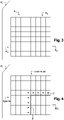
- the image IC j thus partitioned is represented at picture 3 .
- the image IC j is partitioned into four blocks B 1 , B 2 , B 3 and B 4 .
- block means coding unit.
- This latter terminology is notably used in the HEVC standard, for example in the document “ B. Bross, W.-J. Han, J.-R. Ohm, GJ Sullivan, and T. Wiegand, "High efficiency video coding (HEVC) text specification draft 10," document JCTVC-L1003 of JCT-VC, Geneva, CH, 14-23 January 2013 ".
- such a coding unit groups together sets of pixels of rectangular or square shape, also called blocks, macroblocks, or else sets of pixels having other geometric shapes.
- Said blocks B 1 , B 2 , ..., B u , ..., B S are intended to be coded according to a predetermined traversal order, which is for example of the raster scan type. This means that the blocks are coded one after the other, from left to right.
- the blocks B 1 , B 2 , B 3 and B 4 have a square shape and all have the same size.
- the last blocks on the left and the last blocks at the bottom may not be square.
- the blocks may for example be rectangular in size and/or not aligned with each other.
- Each block can moreover itself be divided into sub-blocks which are themselves subdividable.
- the coder CO selects as current block a first block to be coded B u of the image IC j , such as for example the first block B 1 .
- the current block B u is predicted by known intra and/or inter prediction techniques.
- the block B u is predicted with respect to at least one predictor block in accordance with a prediction mode selected from among a plurality of predetermined prediction modes MP 0 , MP 1 ,..., MP v ,..., MP Q where 0 ⁇ v ⁇ Q+1.
- the predetermined prediction modes are of the intra type and Q is equal to 4.
- Such a predictor block is for example a block of pixels which has already been coded or else coded then decoded or not.
- Such a predictor block is stored beforehand in the buffer memory MT_CO of the coder CO as shown in picture 2 .
- an optimal predictor block BP opt is obtained following a competition between said predetermined prediction modes, for example by minimizing a bitrate distortion criterion well known to those skilled in the art. .
- the block BP opt is considered as an approximation of the current block B u .
- the information relating to this prediction is intended to be written into a signal or data stream to be transmitted to a decoder. Such information includes in particular the type of prediction (inter or intra), and if applicable, the mode of prediction selected, the type of partitioning of the current block if the latter has been subdivided, the reference image index and the displacement vector used in the case where an inter prediction mode has been selected. This information is compressed by the CO encoder.
- the data relating to the current block B u are compared with the data of the predictor block BP opt . More specifically, during this step, the difference between the obtained predictor block BP opt and the current block B u is conventionally calculated.
- a set of residual data, called residual block Br u is then obtained at the end of step C4.
- Steps C3 and C4 are implemented by a predictive coding software module PRED1_CO represented on the picture 2 , which module is controlled by the microprocessor ⁇ P of the processing unit UT_CO.
- the residue block Br u is transformed according to a conventional direct transformation operation such as for example a discrete cosine transformation of the DCT type or a wavelet transformation of the DWT type, to produce a transformed block Bt u .
- a transform software module MT_CO as represented picture 2 , which module is controlled by the microprocessor ⁇ P of the processing unit UT_CO.
- the transformed block Bt u is quantized according to a conventional quantization operation, such as for example scalar or vector quantization.
- a block Bq u of NxN quantized coefficients is then obtained, where N is an integer greater than or equal to 1.
- Such a step is performed by means of a quantization software module MQ_CO as represented in picture 2 , which module is controlled by the microprocessor ⁇ P of the processing unit UT_CO.
- the quantized coefficients of the block Bq u are scanned in a predefined order. In the example shown, it is a conventional zigzag path, in increasing order of frequency.
- a reading software module ML_CO as shown in figure 2 , which module is controlled by the microprocessor ⁇ P of the processing unit UT_CO.
- Such an entropy coding step is implemented by an entropy coding software module MCE represented on the picture 2 , which module is controlled by the microprocessor ⁇ P of the processing unit UT_CO.
- the entropic coding module MCE is for example of the CABAC (“Context Adaptive Binary Arithmetic Coder”) type. It may also be a Huffman coder known as such.
- At least one coefficient ⁇ i of the one-dimensional vector RQ u having a non-zero amplitude and a + or - sign is selected.
- such a selection is advantageously implemented using a predetermined criterion which is a function of the prediction mode selected in the prediction step C3.
- Such a selection step is carried out by a selection software module SEL_CO, as shown in figure 2 , which module is controlled by the microprocessor ⁇ P of the processing unit UT_CO.
- said predetermined selection criterion consists of a table TA recorded in a memory (not shown) of the coder C0 which associates with each of said predetermined prediction modes an ordered list of the coefficients of the one-dimensional vector RQ u , the order of the coefficients of a list being variable from one prediction mode to another.
- the coefficients ⁇ 0 , ⁇ 1 ,..., ⁇ i ,..., ⁇ N 2 -1 are sixteen in number and there are five predetermined prediction modes MP 0 , MP 1 , MP 2 , MP3 , MP4 .
- the table TA is then presented in the following form:
- the row which corresponds to the prediction mode which was used to predict the current block B u is selected from the table TA. For example, if it is the MP 3 prediction mode, the row of coefficient indices corresponding to this mode of prediction is selected.
- the coefficients ⁇ 0 to ⁇ 15 are then traversed in the order given by the line of coefficient indices selected, i.e. respectively 12, 13, 14, 15, 0, 1, 2, 3, 4, 5, 6, 7 , 8, 9, 10, 11.
- an order by increasing or decreasing non-zero amplitude of the coefficients of the one-dimensional vector RQ u is selected according to the predetermined prediction mode which has been selected to predict the current block B u .
- selection criteria are in no way limiting, from the moment the criterion takes account of the prediction mode selected in the prediction step C3, to identify the coefficients whose sign will be the most predictable.
- step C10 shown in figure 1 the coding of the signs of the coefficients of the one-dimensional vector RQ u whose indices have not been retained in the list L is carried out in a conventional manner.
- Such a coding step is performed by a sign coding software module MCS_CO, as shown in picture 2 , which module is controlled by the microprocessor ⁇ P of the processing unit UT_CO.
- the signs +, -, +, -, + corresponding respectively to the coefficients ⁇ 0 , ⁇ 2 , ⁇ 6 , ⁇ 7 , ⁇ 9 are then coded in a manner known per se.
- the sign + is coded by a bit at zero
- the sign - is coded by a bit at one.
- Such a sign prediction step is performed by a sign prediction software module PRED2_CO, as shown in picture 2 , which module is controlled by the microprocessor ⁇ P of the processing unit UT_CO.
- Each of these four residual blocks are decoded so as to respectively obtain four decoded residual blocks BDr u0 , BDr u1 , BDr u2 , BDr u3 .
- the predictor block BP opt obtained in the aforementioned prediction step C3 is added to each of these four decoded residual blocks, which makes it possible to obtain four decoded blocks BDu 0 , BD u1 , BD u2 , u3 comics.
- these four blocks decoded only one is the real decoded block resulting from the coding of the current block Bu.
- a plausibility test is then carried out for each of the decoded blocks BDu 0 , BD u1 ,..., BD ud ,..., BD uW-1 , with a plausibility criterion, where 0 ⁇ d ⁇ W .
- the plausibility test consists in applying a criterion for minimizing the difference between the decoded pixels of the current image IC j , which are represented by points on the figure 4 , and the pixels of each decoded block BDu 0 , BD u1 ,..., BD ud ,..., BDu W-1 along their respective boundary F represented by hatching on the figure 4 .
- This criterion is a mathematical operator denoted SM(BD ud , IC j ).
- the operator SM(BD ud , IC j ) is representative of the quadratic error along the boundary F of the decoded residual block BDr u with the image IC j .
- a simplified criterion can be used, where the mean of the pixels of the image IC j along the border F is compared with the mean of the pixels of the decoded block BD ud .
- the decoded residual block is identified, among the decoded residual blocks BDr u0 , BDr u1 , ..., BDr uW-1 , which is associated with the decoded block BD udmin .
- the signs associated with the coefficients whose indices I 0 to I K -1 are contained in the list L are then considered as the predicted values of the signs of the coefficients of said residual block associated with the identified decoded residual block.
- Such a calculation step is carried out by a calculation software module CAL_CO, as shown in picture 2 , which module is controlled by the microprocessor ⁇ P of the processing unit UT_CO.
- the prediction of the signs is false since the predicted values of sign Sp 1 and Sp 2 are respectively ⁇ +,+ ⁇ while the values of the signs of the coefficients ⁇ 14 and ⁇ 15 are respectively ⁇ -,+ ⁇ . Consequently, the indicator Id takes the binary values 01 to indicate that the prediction of the sign of the coefficient ⁇ 14 is false and that the prediction of the sign of the coefficient ⁇ 15 is exact.
- Such a calculation step is carried out by an information coding software module MCI_CO, as shown in figure 2 , which module is controlled by the microprocessor ⁇ P of the processing unit UT_CO.
- a signal or data stream ⁇ which contains all of the encoded data of the block of quantized coefficients Bq u and the encoded identifier Id is then delivered. Such a stream is then transmitted by a communication network (not shown), to a remote terminal. This includes the DO decoder shown in figure 5 .
- the stream ⁇ further comprises certain information encoded by the coder CO, such as the type of prediction (inter or intra), and if applicable, the prediction mode selected, the type of partitioning of the block if the latter has been partitioned, the reference image index and the displacement vector used in the inter prediction mode.
- step C14 the block Bq u is dequantized according to a conventional dequantization operation, which is the inverse operation of the quantization carried out in step C6.
- a block of dequantized coefficients BDq u is then obtained.
- Such a dequantization step is performed by an inverse quantization software module MT -1 _CO, as shown in picture 2 , which module is controlled by the microprocessor ⁇ P of the processing unit UT_CO.
- step C15 the inverse transformation of the block of dequantized coefficients BDq u is carried out, which is the inverse operation of the direct transformation carried out in step C5 above.
- a decoded residual block BDr u is then obtained.
- Such an operation is performed by an inverse transform software module MT -1 _CO, as represented picture 2 , which module is controlled by the microprocessor ⁇ P of the processing unit UT_CO.
- the decoded block BD u is constructed by adding to the predictor block BP opt obtained in the aforementioned step C3 the decoded residue block BDr u . It should be noted that this last block is the same as the decoded block obtained at the end of the process for decoding the image IC j which will be described later in the description.
- the decoded block BD u is then stored in the buffer memory MT_CO of the figure 2 , in order to be used by the coder CO as a predictor block of a following block to be coded.
- Such a step is implemented by an inverse predictive coding software module PRED -1 _CO represented on the picture 2 , which module is controlled by the microprocessor ⁇ P of the processing unit UT_CO.
- the coder CO tests whether the current block B u which has just been coded is the last block of the image IC j .
- the coding process is terminated.
- step C2 of selecting the next block to be coded is again carried out in accordance with the aforementioned raster scan traversal order, then the steps C3 to C17 are repeated for this next block selected .
- decoding method is implemented in software or hardware by modifications of a decoder initially conforming to the HEVC standard.
- the decoding method according to the invention is represented in the form of an algorithm comprising steps D1 to D15 as represented in figure 6 .
- the DO decoder comprises a memory MEM_DO comprising a buffer memory MT_DO, a processing unit UT_DO equipped for example with a microprocessor ⁇ P and controlled by a computer program PG_DO which implements the decoding method according to the invention.
- the code instructions of the computer program PG_DO are for example loaded into a RAM memory before being executed by the processor of the processing unit UT_DO.
- the decoding process represented on the figure 6 applies to any current image of a sequence SQ of images to be decoded.
- information representative of the current image IC j to be decoded is identified in a signal or data stream ⁇ received at the decoder, as delivered following the method of encoding the figure 1 .
- Such an identification step is implemented by a flow analysis identification module MI_DO, as shown in figure 5 , said module being controlled by the microprocessor ⁇ P of the processing unit UT_DO.
- Said quantized residues RQ 1 , RQ 2 , ..., RQ u ,..., RQs are intended to be decoded according to a predetermined traversal order, which is for example sequential, that is to say that said residues are intended to be decoded one after the other according to the raster scan order in which they were encoded.
- the blocks to be decoded have a square shape and all have the same size.
- the last blocks on the left and the last blocks at the bottom may not be square.
- the blocks may for example be rectangular in size and/or not aligned with each other.
- Each block can moreover itself be divided into sub-blocks which are themselves subdividable.
- the current block B u to be decoded is predicted by known intra and/or inter prediction techniques.
- the block B u to be decoded is predicted with respect to at least one predictor block in accordance with a prediction mode selected from among a plurality of predetermined prediction modes MP 0 , MP 1 ,..., MP v ,.. ., MP Q where 0 ⁇ v ⁇ Q+1.
- the predetermined prediction modes are of the intra type and Q is equal to 4.
- the selected prediction mode is directly read in the stream ⁇ in the case where the coder CO of the figure 2 signaled this mode to the DO decoder of the figure 5 .
- the prediction mode is selected at the decoder DO by placing said predetermined prediction modes in competition, for example by minimizing a bitrate distortion criterion well known to those skilled in the art.
- Such a predictor block is for example a block of pixels which has already been decoded or not.
- Such a predictor block is stored beforehand in the buffer memory MT_DO of the decoder DO as shown in figure 5 .
- an optimal predictor block BP opt conforming to the selected prediction mode is obtained.
- the BP opt block is a approximation of the current block B u to be decoded.
- the information relating to this prediction is read from the data stream ⁇ . Such information includes in particular the type of prediction (inter or intra), the type of partitioning of the current block if the latter has been subdivided, the reference image index and the displacement vector used in the case where a mode of inter prediction has been selected. This information will subsequently be decoded in a conventional manner.
- Step D3 is implemented by a predictive decoding software module PRED1_DO represented on the figure 5 , which module is controlled by the microprocessor ⁇ P of the processing unit UT_DO.
- Such an entropy decoding step is implemented by an entropy decoding software module MDE represented on the figure 5 , which module is controlled by the microprocessor ⁇ P of the processing unit UT_DO.
- the entropy decoding module MDE is for example of the CABAC type. It may also be a Huffman decoder known as such.
- At least one coefficient of the one-dimensional vector RQ u having a non-zero amplitude and a + or - sign is selected.
- such a selection is advantageously implemented using a predetermined criterion which is a function of the prediction mode selected in the prediction step D3.
- the selection step D5 is in all respects identical to the selection step C9 carried out during the coding with reference to the figure 1 .
- Such a selection step is performed by a selection software module SEL_DO, as shown in figure 5 , which module is controlled by the microprocessor ⁇ P of the processing unit UT_DO.
- said predetermined selection criterion consists of a table TA stored in a memory (not shown) of the decoder DO which associates with each of said predetermined prediction modes an ordered list of the coefficients of the one-dimensional vector RQ u , the order of the coefficients of a list being variable from one prediction mode to another.
- the coefficients ⁇ 0 , ⁇ 1 ,..., ⁇ i ,..., ⁇ N 2 -1 are sixteen in number and there are five predetermined prediction modes MP 0 , MP 1 , MP 2 , MP3 , MP4 .
- the table TA is then presented in the following form:
- the line which corresponds to the prediction mode which was used to predict the current block B u to be decoded is chosen from the table TA. For example, if it is the prediction mode MP 3 , the line of coefficient indices corresponding to this prediction mode is selected. The coefficients ⁇ 0 to ⁇ 15 are then traversed in the order given by the line of coefficient indices selected, i.e. respectively 12, 13, 14, 15, 0, 1, 2, 3, 4, 5, 6, 7 , 8, 9, 10, 11.
- a list L ⁇ I 0 , I 1 ,..., I z ,..., I K-1 ⁇ (0 ⁇ z ⁇ K) containing the indices of K coefficients identified in said subset, is then constructed .
- L ⁇ 14,15 ⁇ .
- an order by increasing or decreasing non-zero amplitude of the coefficients of the one-dimensional vector RQ u is selected according to the predetermined prediction mode which has been selected to predict the current block B u to be decoded.
- selection criteria are in no way limiting, from the moment the criterion takes account of the prediction mode selected in the prediction step D3, to identify the coefficients whose sign will be the most predictable.
- a list L ⁇ I 0 , I 1 ,..., I z ,..., I K-1 ⁇ (0 ⁇ z ⁇ K) containing the indices of K coefficients of the one-dimensional vector RQ u .
- the conventional way is to decode the signs of the coefficients of the one-dimensional vector RQ u whose indices have not been retained in the list L.
- Such a decoding step is carried out by a sign decoding software module MDS_DO as shown in figure 5 , which module is controlled by the microprocessor ⁇ P of the processing unit UT_DO.
- the signs +, -, +, -, + corresponding respectively to the coefficients ⁇ 0 , ⁇ 2 , ⁇ 6 , ⁇ 7 , ⁇ 9 are then decoded.
- the + sign is reconstructed by reading in the stream ⁇ from one bit to zero, while the - sign is reconstructed by reading in the stream ⁇ from one bit to one.
- Such a sign prediction step is performed by a sign prediction software module PRED2_DO as shown in figure 5 , which module is controlled by the microprocessor ⁇ P of the processing unit UT_DO.
- Said sign prediction step D7 is in all respects identical to the sign prediction step C11 carried out during the coding with reference to the figure 1 .
- Each of these four residual blocks are decoded so as to respectively obtain four decoded residual blocks BDr u0 , BDr u1 , BDr u2 , BDr u3 .
- the predictor block BP opt obtained in the aforementioned prediction step D3 is added to each of these four decoded residual blocks, which makes it possible to obtain four decoded blocks BDu 0 , BD u1 , BD u2 , u3 comics.
- these four decoded blocks only one is the real decoded block as obtained after the decoding of the current block B u to be decoded.
- a plausibility test is then carried out for each of the decoded blocks BDu 0 , BD u1 ,..., BD ud ,..., BD uW-1 , with a plausibility criterion.
- the plausibility test consists in applying a criterion for minimizing the difference between the decoded pixels of the current image IC j , which are represented by points on the figure 4 , and the pixels of each decoded block BDu 0 , BD u1 ,..., BD ud ,..., BD uW-1 along their respective boundary F represented by hatching on the figure 4 .
- This criterion is a mathematical operator denoted SM(BD ud , IC j ).
- the operator SM(BD ud , IC j ) is representative of the quadratic error along the boundary F of the decoded residual block BDr u with the image IC j .
- a simplified criterion can be used, where the mean of the pixels of the image IC j along the border F is compared with the mean of the pixels of the decoded block BD ud .
- the decoded residual block is identified, among the decoded residual blocks BDr u0 , BDr u1 , ..., BDr uW-1 , which is associated with the decoded block BD udmin .
- the signs associated with the coefficients whose indices I 0 to I K -1 are contained in the list L are then considered as the predicted values of the signs of the coefficients of said residual block associated with the identified decoded residual block.
- Such a reading step is performed by a reading software module ML_DO as shown in figure 5 , which module is controlled by the microprocessor ⁇ P of the processing unit UT_DO.
- the prediction of the signs is false since the predicted values of sign Sp 1 and Sp 2 are respectively ⁇ +,+ ⁇ while the values of the signs of the coefficients ⁇ 14 and ⁇ 15 are respectively ⁇ -,+ ⁇ . Consequently, the read information Id is “01” to indicate that the prediction of the sign of the coefficient ⁇ 14 is false and that the prediction of the sign of the coefficient ⁇ 15 is correct.
- Such a sign decoding step is carried out by a calculation software module CAL_DO as shown in figure 5 , which module is controlled by the microprocessor ⁇ P of the processing unit UT_DO.
- step D10 the quantified residue RQ u is dequantized according to a conventional dequantization operation, which is in all respects identical to the dequantization step carried out in step C14 of the figure 1 .
- a decoded dequantized block BDt u is then obtained.
- Such a dequantization step is performed by an inverse quantization software module MQ -1 _DO as shown in figure 5 , which module is controlled by the microprocessor ⁇ P of the processing unit UT_DO.
- step D11 the inverse transformation of the block of dequantized coefficients BDt u is carried out, which is in all respects identical to the inverse transformation step carried out in step C15 of the figure 1 .
- a decoded residual block BDr u is then obtained.
- Such an operation is performed by an inverse transform software module MT -1 _DO, as represented figure 5 , which module is controlled by the microprocessor ⁇ P of the processing unit UT_DO.
- step D12 the current block B u is reconstructed by adding to the decoded current residual block BDr u the predictor block BP opt obtained in step D3.
- Said step D12 is implemented by an inverse prediction software module PRED -1 _DO represented on the figure 5 , which module is controlled by the microprocessor ⁇ P of the processing unit UT_DO.
- a decoded block BD u is then obtained and stored in the buffer memory MT_DO of the figure 5 , in order to be used by the decoder DO as a predictor block of a following block to be decoded.
- step D13 said decoded block BD u is written in a decoded image ID j .
- One such step is implementing an image reconstruction URI software module as shown in Fig. figure 5 , said module being controlled by the microprocessor ⁇ P of the processing module UT_DO.
- the decoder DO tests whether the current block BD u which has just been decoded is the last block contained in the stream ⁇ .
- next residual block to be decoded is selected during step D2 in accordance with the aforementioned raster scan traversal order.
Claims (12)
- Verfahren zur Codierung mindestens eines in Blöcke aufgeteilten Bildes (ICj), das für einen zu codierenden aktuellen Block (Bu) die folgenden Schritte umsetzt:- Vorhersagen (C3) des aktuellen Blocks entsprechend einem Vorhersagemodus, der aus einer Vielzahl vorgegebener Vorhersagemodi (MP0, MP1,..., MPv, ..., MPQ) ausgewählt wird,- Erhalten (C3) eines Vorhersageblocks (BPopt),- Ermitteln (C4) eines Restdatenblocks (BRu) , der für die Differenz zwischen dem erhaltenen Vorhersageblock und dem aktuellen Block repräsentativ ist, wobei die Restdaten eine Amplitude und ein Vorzeichen haben können,- Berechnen (C5) eines transformierten Blocks (Btu) durch Transformation des Restdatenblocks,- Berechnen (C6) eines Blocks von NxN quantifizierten Koeffizienten (Bqu) durch Quantifizierung des transformierten Blocks,- Durchsuchen (C7) der quantifizierten Koeffizienten in einer definierten Reihenfolge, nach dessen Ablauf ein eindimensionaler Vektor von N2 Koeffizienten (ε0, ε1,..., εi,..., εN 2 -1) erhalten wird,- entropisches Codieren (C8) der Amplitudeninformationen, die mit jedem der Koeffizienten verknüpft sind,- Abtasten (C9) der N2 Koeffizienten in einer vorgegebenen Reihenfolge,- Auswählen (C9) von K ersten Koeffizienten, die mit einer Nichtnullamplitude und einem Vorzeichen versehen sind, in der vorgegebenen Reihenfolge, wobei K ein vorgegebener Wert wie 0≤K≤N2-1 ist,- Erhalten (C11) von K vorhergesagten Werten (Sp1, Sp2,..., SpK) des Vorzeichens der jeweils abgetasteten K ersten Koeffizienten,- Berechnen (C12) einer Information, die für die Differenz zwischen den K vorhergesagten Vorzeichenwerten (Sp1, Sp2,..., SpK) und jeweils den entsprechenden Vorzeichenwerten (S1, S2,..., SK) der abgetasteten K ersten Koeffizienten repräsentativ ist,- Codieren (C13) der berechneten Information,- Codieren (C10) der Vorzeichen der Koeffizienten, die nicht ausgewählt wurden,wobei das Verfahren zur Codierung dadurch gekennzeichnet ist, dass der Schritt des Abtastens (C9) die vorgegebene Reihenfolge in Abhängigkeit vom ausgewählten Vorhersagemodus auswählt.
- Verfahren zur Codierung nach Anspruch 1, wobei der Schritt des Erhaltens der K vorhergesagten Vorzeichenwerte abhängig ist von zuvor codierten und anschließend decodierten Pixeln des aktuellen Bildes, die sich entlang (F) des aktuellen Blocks befinden.
- Verfahren zur Codierung nach Anspruch 1 oder Anspruch 2, wobei die Schritte des Abtastens und des Auswählens anhand einer Tabelle (TA) umgesetzt werden, die jeden der vorgegebenen Vorhersagemodi mit einer geordneten Liste der Koeffizienten verknüpft, wobei die Reihenfolge der Koeffizienten einer Liste von einem Vorhersagemodus zum anderen variabel ist.
- Vorrichtung (CO) zur Codierung mindestens eines in Blöcke aufgeteilten Bildes, das für einen zu codierenden aktuellen Block umfasst:- Mittel (PRED1_CO) zum Vorhersagen des aktuellen Blocks entsprechend einem Vorhersagemodus, der aus einer Vielzahl vorgegebener Vorhersagemodi (MP0, MP1,..., MPv,..., MPQ) ausgewählt wird,- Mittel (PRED1_CO) zum Ermitteln eines Restdatenblocks (BRu), der für die Differenz zwischen einem Vorhersageblock, der nach Aktivierung der Vorhersagemittel erhalten wird, und dem aktuellen Block repräsentativ ist, wobei die Restdaten eine Amplitude und ein Vorzeichen haben können,- Mittel (MT_CO) zum Berechnen eines transformierten Blocks (Btu) durch Transformation des Restdatenblocks,- Mittel (MQ_CO) zum Berechnen eines Blocks von NxN quantifizierten Koeffizienten (Bqu) durch Quantifizierung des transformierten Blocks,- Mittel (ML_CO) zum Durchsuchen der quantifizierten Koeffizienten in einer definierten Reihenfolge, nach dessen Ablauf ein eindimensionaler Vektor von N2 Koeffizienten (ε0, ε1,..., εi,..., εN 2 -1) erhalten wird,- Mittel (MCE) zum entropischen Codieren der Amplitudeninformationen, die mit jedem der Koeffizienten verknüpft sind,- Mittel zum Abtasten der N2 Koeffizienten in einer vorgegebenen Reihenfolge,- Mittel (SEL_CO) zum Auswählen von K ersten Koeffizienten, die mit einer Nichtnullamplitude und einem Vorzeichen versehen sind, in der vorgegebenen Reihenfolge, wobei K ein vorgegebener Wert wie 0≤K≤N2-1 ist,- Mittel (PRED2_CO) zum Erhalten von K vorhergesagten Werten des Vorzeichens der jeweils abgetasteten K ersten Koeffizienten,- Mittel (CAL_CO) zum Berechnen einer Information (Id), die für die Differenz zwischen den K vorhergesagten Vorzeichenwerten und den entsprechenden Vorzeichenwerten der abgetasteten K ersten Koeffizienten repräsentativ ist,- Mittel (MCI_CO) zum Codieren der berechneten Information,- Mittel (MCS CO) zum Codieren der Vorzeichen der Koeffizienten, die nicht ausgewählt wurden,wobei die Vorrichtung zur Codierung dadurch gekennzeichnet ist, dass die Mittel zum Abtasten die vorgegebene Reihenfolge in Abhängigkeit vom ausgewählten Vorhersagemodus auswählen.
- Computerprogramm, das Programmcodeanweisungen für die Ausführung der Schritte des Verfahrens zur Codierung nach einem der Ansprüche 1 bis 3 umfasst, wenn das Programm auf einem Computer ausgeführt wird.
- Speichermedium, das durch einen Computer lesbar ist, auf dem ein Computerprogramm gespeichert ist, das Anweisungen für die Ausführung der Schritte des Verfahrens zur Codierung nach einem der Ansprüche 1 bis 3 umfasst, wenn das Programm auf einem Computer ausgeführt wird.
- Verfahren zur Decodierung eines für mindestens ein in Blöcke aufgeteiltes Bild (ICj) repräsentativen Datensignals (ϕ), das für einen zu decodierenden aktuellen Block (Bu) ist, die Schritte umsetzt:- Ermitteln (D2) eines eindimensionalen Vektors von N2 quantifizierten Koeffizienten (ε0, ε1,..., εi,..., εN 2 -1) zum aktuellen Block im Datensignal, wobei mindestens ein Koeffizient des Vektors mit einer Amplitude und einem Vorzeichen versehen ist,- Vorhersagen (D3) des aktuellen Blocks entsprechend einem ausgewählten Vorhersagemodus unter einer Vielzahl vorgegebener Vorhersagemodi (MP0, MP1,..., MPv,..., MPQ),- entropisches Decodieren (D4) der Amplitudeninformationen, die mit jedem der N2 Koeffizienten verknüpft sind,- Abtasten (D5) der N2 Koeffizienten in einer vorgegebenen Reihenfolge,- Auswählen (D5) von K ersten Koeffizienten, die mit einer Nichtnullamplitude und einem Vorzeichen versehen sind, in der vorgegebenen Reihenfolge, wobei K ein vorgegebener Wert wie 0≤K≤N2-1 ist,- Erhalten (D7) von K vorhergesagten Werten (Sp1, Sp2,..., SpK) des Vorzeichens der jeweils abgetasteten K ersten Koeffizienten,- Ermitteln (D8) einer Information (Id) im Datensignal (ϕ), die für die Differenz zwischen den K vorhergesagten Vorzeichenwerten (Sp1, Sp2,..., SpK) und jeweils den entsprechenden Vorzeichenwerten (S1, S2,...,SK) der abgetasteten K ersten Koeffizienten repräsentativ ist,- Rekonstruieren (D9) der K Vorzeichen mithilfe der vorhergesagten K Vorzeichenwerte und der entsprechenden repräsentativen Information,- Decodieren (D6) der Vorzeichen der Koeffizienten, die nicht ausgewählt wurden,- Berechnen (D10) eines decodierten dequantifizierten Blocks (BDtu) durch Dequantifizierung des eindimensionalen Vektors,- Berechnen (D11) eines decodierten Restblocks (BDru) durch Transformation des decodierten dequantifizierten Blocks,- Rekonstruieren (D12) des aktuellen Blocks durch Hinzufügen eines Vorhersageblocks, der nach Ablauf der Vorhersage erhalten wird, zum decodierten Restblock, wobei das Verfahren zur Decodierung dadurch gekennzeichnet ist, dass der Schritt des Abtastens (D5) die vorgegebene Reihenfolge in Abhängigkeit vom ausgewählten Vorhersagemodus auswählt.
- Verfahren zur Decodierung nach Anspruch 7, wobei der Schritt des Erhaltens der K vorhergesagten Vorzeichenwerte abhängig ist von zuvor decodierten Pixeln des aktuellen Bildes, die sich entlang (F) des aktuellen Blocks befinden.
- Verfahren zur Decodierung nach Anspruch 7 oder Anspruch 8, wobei die Schritte des Abtastens und des Auswählens anhand einer Tabelle (TA) umgesetzt werden, die einen bestimmten Vorhersagemodus mit einer geordneten Liste der Koeffizienten verknüpft, wobei die Reihenfolge der Koeffizienten einer Liste von einem Vorhersagemodus zum anderen variabel ist.
- Vorrichtung (DO) zur Decodierung eines für mindestens ein in Blöcke aufgeteiltes Bild (ICj) repräsentativen Datensignals (ϕ), das für einen zu decodierenden aktuellen Block umfasst:- Mittel (MI DO) zum Ermitteln eines eindimensionalen Vektors von N2 quantifizierten Koeffizienten (ε0, ε1,..., εi,..., εN 2 -1) zum aktuellen Block im Datensignal, wobei mindestens ein Koeffizient des Vektors mit einer Amplitude und einem Vorzeichen versehen ist,- Mittel (PRED1_DO) zum Vorhersagen des aktuellen Blocks entsprechend einem ausgewählten Vorhersagemodus unter einer Vielzahl vorgegebener Vorhersagemodi (MP0, MP1,..., MPv,..., MPQ),- Mittel (MDE) zum entropischen Decodieren der Amplitudeninformationen, die mit jedem der N2 Koeffizienten verknüpft sind,- Mittel zum Abtasten der N2 Koeffizienten in einer vorgegebenen Reihenfolge,- Mittel (SEL DO) zum Auswählen von K ersten Koeffizienten, die mit einer Nichtnullamplitude und einem Vorzeichen versehen sind, in der vorgegebenen Reihenfolge, wobei K ein vorgegebener Wert wie 0≤K≤N2-1 ist,- Mittel (PRED2_DO) zum Erhalten von K vorhergesagten Werten des Vorzeichens der jeweils K ersten abgetasteten Koeffizienten,- Mittel (ML_DO) zum Ermitteln einer Information (Id) im Datensignal, die für die Differenz zwischen den K vorhergesagten Vorzeichenwerten und jeweils den entsprechenden Vorzeichenwerten der abgetasteten K ersten Koeffizienten repräsentativ ist,- Mittel (CAL_DO) zum Rekonstruieren der K Vorzeichen mithilfe der vorhergesagten K Vorzeichenwerte und der entsprechenden repräsentativen Information,- Mittel (MDS DO) zum Decodieren der Vorzeichen der Koeffizienten, die nicht ausgewählt wurden,- Mittel (MQ-1_DO) zum Berechnen eines decodierten dequantifizierten Blocks (BDtu) durch Dequantifizierung des eindimensionalen Vektors,- Mittel (MT-1_DO) zum Berechnen eines decodierten Restblocks (BDru) durch Transformation des decodierten dequantifizierten Blocks,- Mittel (PRED-1_DO) zum Rekonstruieren des aktuellen Blocks durch Hinzufügen eines Vorhersageblocks, der nach Ablauf der Vorhersage erhalten wird, zum decodierten Restblock,wobei das Verfahren zur Decodierung dadurch gekennzeichnet ist, dass die Mittel zum Abtasten die vorgegebene Reihenfolge in Abhängigkeit vom ausgewählten Vorhersagemodus auswählen.
- Computerprogramm, das Programmcodeanweisungen für die Umsetzung des Verfahrens zur Decodierung nach einem der Ansprüche 7 bis 9 umfasst, wenn das Programm auf einem Computer ausgeführt wird.
- Speichermedium, das durch einen Computer lesbar ist, auf dem ein Computerprogramm gespeichert ist, das Anweisungen für die Ausführung der Schritte des Verfahrens zur Decodierung nach einem der Ansprüche 7 bis 9 umfasst, wenn das Programm auf einem Computer ausgeführt wird.
Applications Claiming Priority (2)
| Application Number | Priority Date | Filing Date | Title |
|---|---|---|---|
| FR1360444A FR3012714A1 (fr) | 2013-10-25 | 2013-10-25 | Procede de codage et de decodage d'images, dispositif de codage et de decodage d'images et programmes d'ordinateur correspondants |
| PCT/FR2014/052673 WO2015059400A1 (fr) | 2013-10-25 | 2014-10-21 | Procédé de codage et de décodage d'images, dispositif de codage et de décodage d'images et programmes d'ordinateur correspondants |
Publications (2)
| Publication Number | Publication Date |
|---|---|
| EP3061246A1 EP3061246A1 (de) | 2016-08-31 |
| EP3061246B1 true EP3061246B1 (de) | 2022-04-13 |
Family
ID=49817045
Family Applications (1)
| Application Number | Title | Priority Date | Filing Date |
|---|---|---|---|
| EP14824875.0A Active EP3061246B1 (de) | 2013-10-25 | 2014-10-21 | Verfahren zur codierung und decodierung von bildern, vorrichtung zur codierung und decodierung von bildern und entsprechende computerprogramme |
Country Status (5)
| Country | Link |
|---|---|
| US (1) | US10397570B2 (de) |
| EP (1) | EP3061246B1 (de) |
| CN (1) | CN105723709B (de) |
| FR (1) | FR3012714A1 (de) |
| WO (1) | WO2015059400A1 (de) |
Families Citing this family (10)
| Publication number | Priority date | Publication date | Assignee | Title |
|---|---|---|---|---|
| FR3046321B1 (fr) * | 2015-12-29 | 2018-01-26 | B<>Com | Procede de codage d'une image numerique, procede de decodage, dispositifs, terminal d'utilisateur et programmes d'ordinateurs associes |
| FR3058858A1 (fr) * | 2016-11-15 | 2018-05-18 | Orange | Procede et dispositif de codage et de decodage d'une sequence multi-vues |
| FR3064145A1 (fr) * | 2017-03-16 | 2018-09-21 | Orange | Procede de codage et decodage d'images, dispositif de codage et decodage et programmes d'ordinateur correspondants |
| FR3066873A1 (fr) | 2017-05-29 | 2018-11-30 | Orange | Procedes et dispositifs de codage et de decodage d'un flux de donnees representatif d'au moins une image |
| GB2570711B (en) * | 2018-02-05 | 2023-04-05 | Sony Corp | Data encoding and decoding |
| WO2019190338A1 (en) * | 2018-03-26 | 2019-10-03 | Huawei Technologies Co., Ltd. | A video image encoder, a video image decoder and corresponding methods for motion information coding |
| FR3081656A1 (fr) * | 2018-06-27 | 2019-11-29 | Orange | Procedes et dispositifs de codage et de decodage d'un flux de donnees representatif d'au moins une image. |
| FR3086486A1 (fr) * | 2018-09-21 | 2020-03-27 | Orange | Procedes et dispositifs de codage et de decodage d'un flux de donnees representatif d'au moins une image. |
| FR3086487A1 (fr) * | 2018-09-21 | 2020-03-27 | Orange | Procedes et dispositifs de codage et de decodage d'un flux de donnees representatif d'au moins une image. |
| FR3093884A1 (fr) * | 2019-03-15 | 2020-09-18 | Orange | Procédés et dispositifs de codage et de décodage d'une séquence vidéo multi-vues |
Family Cites Families (2)
| Publication number | Priority date | Publication date | Assignee | Title |
|---|---|---|---|---|
| JP5590133B2 (ja) * | 2010-09-30 | 2014-09-17 | 富士通株式会社 | 動画像符号化装置、動画像符号化方法、動画像符号化用コンピュータプログラム、動画像復号装置及び動画像復号方法ならびに動画像復号用コンピュータプログラム |
| KR20130049524A (ko) * | 2011-11-04 | 2013-05-14 | 오수미 | 인트라 예측 블록 생성 방법 |
-
2013
- 2013-10-25 FR FR1360444A patent/FR3012714A1/fr not_active Withdrawn
-
2014
- 2014-10-21 US US15/031,966 patent/US10397570B2/en active Active
- 2014-10-21 CN CN201480058095.0A patent/CN105723709B/zh active Active
- 2014-10-21 WO PCT/FR2014/052673 patent/WO2015059400A1/fr active Application Filing
- 2014-10-21 EP EP14824875.0A patent/EP3061246B1/de active Active
Also Published As
| Publication number | Publication date |
|---|---|
| WO2015059400A1 (fr) | 2015-04-30 |
| US10397570B2 (en) | 2019-08-27 |
| CN105723709B (zh) | 2019-02-05 |
| FR3012714A1 (fr) | 2015-05-01 |
| EP3061246A1 (de) | 2016-08-31 |
| US20160277736A1 (en) | 2016-09-22 |
| CN105723709A (zh) | 2016-06-29 |
Similar Documents
| Publication | Publication Date | Title |
|---|---|---|
| EP3061246B1 (de) | Verfahren zur codierung und decodierung von bildern, vorrichtung zur codierung und decodierung von bildern und entsprechende computerprogramme | |
| EP2991351B1 (de) | Verfahren zur dekodierung von bildern | |
| EP2985998B1 (de) | Aufzeichnungsmedium zur speicherung von kodierten bilddaten | |
| EP3058737A1 (de) | Verfahren zur codierung und decodierung von bildern, vorrichtung zur codierung und decodierung von bildern und entsprechende computerprogramme | |
| EP3075155B1 (de) | Verfahren zur codierung und decodierung von bildern, vorrichtung zur codierung und decodierung von bildern und entsprechende computerprogramme | |
| EP4344203A2 (de) | Verfahren zur bildkodierung und -dekodierung, kodierungs- und dekodierungsvorrichtung und computerprogramme dafür | |
| FR3046321A1 (fr) | Procede de codage d'une image numerique, procede de decodage, dispositifs, terminal d'utilisateur et programmes d'ordinateurs associes | |
| EP3180914A1 (de) | Bildcodierungs- und decodierungsverfahren, bildcodierungs- und decodierungsvorrichtung sowie entsprechende computerprogramme | |
| EP3409016A1 (de) | Verfahren zur codierung und decodierung von daten, vorrichtung zur codierung und decodierung von daten und entsprechende computerprogramme | |
| WO2018073523A1 (fr) | Procédé de codage et de décodage de paramètres d'image, dispositif de codage et de décodage de paramètres d'image et programmes d'ordinateur correspondants | |
| EP3725080A1 (de) | Verfahren und vorrichtungen zur codierung und decodierung einer für ein omnidirektionales video repräsentativen mehrfachansichtsvideosequenz | |
| WO2019008253A1 (fr) | Procédé de codage et décodage d'images, dispositif de codage et décodage et programmes d'ordinateur correspondants | |
| FR3064145A1 (fr) | Procede de codage et decodage d'images, dispositif de codage et decodage et programmes d'ordinateur correspondants | |
| FR2988960A1 (fr) | Procede de codage et decodage d'images, dispositif de codage et decodage et programmes d'ordinateur correspondants |
Legal Events
| Date | Code | Title | Description |
|---|---|---|---|
| PUAI | Public reference made under article 153(3) epc to a published international application that has entered the european phase |
Free format text: ORIGINAL CODE: 0009012 |
|
| 17P | Request for examination filed |
Effective date: 20160523 |
|
| AK | Designated contracting states |
Kind code of ref document: A1 Designated state(s): AL AT BE BG CH CY CZ DE DK EE ES FI FR GB GR HR HU IE IS IT LI LT LU LV MC MK MT NL NO PL PT RO RS SE SI SK SM TR |
|
| AX | Request for extension of the european patent |
Extension state: BA ME |
|
| DAX | Request for extension of the european patent (deleted) | ||
| STAA | Information on the status of an ep patent application or granted ep patent |
Free format text: STATUS: EXAMINATION IS IN PROGRESS |
|
| 17Q | First examination report despatched |
Effective date: 20190717 |
|
| STAA | Information on the status of an ep patent application or granted ep patent |
Free format text: STATUS: EXAMINATION IS IN PROGRESS |
|
| RAP1 | Party data changed (applicant data changed or rights of an application transferred) |
Owner name: ORANGE |
|
| RAP3 | Party data changed (applicant data changed or rights of an application transferred) |
Owner name: ORANGE |
|
| REG | Reference to a national code |
Ref country code: DE Ref legal event code: R079 Ref document number: 602014083251 Country of ref document: DE Free format text: PREVIOUS MAIN CLASS: H04N0019180000 Ipc: H04N0019463000 |
|
| GRAP | Despatch of communication of intention to grant a patent |
Free format text: ORIGINAL CODE: EPIDOSNIGR1 |
|
| STAA | Information on the status of an ep patent application or granted ep patent |
Free format text: STATUS: GRANT OF PATENT IS INTENDED |
|
| RIC1 | Information provided on ipc code assigned before grant |
Ipc: H04N 19/184 20140101ALI20211022BHEP Ipc: H04N 19/157 20140101ALI20211022BHEP Ipc: H04N 19/102 20140101ALI20211022BHEP Ipc: H04N 19/105 20140101ALI20211022BHEP Ipc: H04N 19/18 20140101ALI20211022BHEP Ipc: H04N 19/463 20140101AFI20211022BHEP |
|
| INTG | Intention to grant announced |
Effective date: 20211115 |
|
| RIN1 | Information on inventor provided before grant (corrected) |
Inventor name: HENRY, FELIX |
|
| GRAS | Grant fee paid |
Free format text: ORIGINAL CODE: EPIDOSNIGR3 |
|
| GRAA | (expected) grant |
Free format text: ORIGINAL CODE: 0009210 |
|
| STAA | Information on the status of an ep patent application or granted ep patent |
Free format text: STATUS: THE PATENT HAS BEEN GRANTED |
|
| AK | Designated contracting states |
Kind code of ref document: B1 Designated state(s): AL AT BE BG CH CY CZ DE DK EE ES FI FR GB GR HR HU IE IS IT LI LT LU LV MC MK MT NL NO PL PT RO RS SE SI SK SM TR |
|
| REG | Reference to a national code |
Ref country code: GB Ref legal event code: FG4D Free format text: NOT ENGLISH |
|
| REG | Reference to a national code |
Ref country code: CH Ref legal event code: EP |
|
| REG | Reference to a national code |
Ref country code: DE Ref legal event code: R096 Ref document number: 602014083251 Country of ref document: DE |
|
| REG | Reference to a national code |
Ref country code: IE Ref legal event code: FG4D Free format text: LANGUAGE OF EP DOCUMENT: FRENCH |
|
| REG | Reference to a national code |
Ref country code: AT Ref legal event code: REF Ref document number: 1484308 Country of ref document: AT Kind code of ref document: T Effective date: 20220515 |
|
| REG | Reference to a national code |
Ref country code: LT Ref legal event code: MG9D |
|
| REG | Reference to a national code |
Ref country code: NL Ref legal event code: MP Effective date: 20220413 |
|
| REG | Reference to a national code |
Ref country code: AT Ref legal event code: MK05 Ref document number: 1484308 Country of ref document: AT Kind code of ref document: T Effective date: 20220413 |
|
| PG25 | Lapsed in a contracting state [announced via postgrant information from national office to epo] |
Ref country code: NL Free format text: LAPSE BECAUSE OF FAILURE TO SUBMIT A TRANSLATION OF THE DESCRIPTION OR TO PAY THE FEE WITHIN THE PRESCRIBED TIME-LIMIT Effective date: 20220413 |
|
| PG25 | Lapsed in a contracting state [announced via postgrant information from national office to epo] |
Ref country code: SE Free format text: LAPSE BECAUSE OF FAILURE TO SUBMIT A TRANSLATION OF THE DESCRIPTION OR TO PAY THE FEE WITHIN THE PRESCRIBED TIME-LIMIT Effective date: 20220413 Ref country code: PT Free format text: LAPSE BECAUSE OF FAILURE TO SUBMIT A TRANSLATION OF THE DESCRIPTION OR TO PAY THE FEE WITHIN THE PRESCRIBED TIME-LIMIT Effective date: 20220816 Ref country code: NO Free format text: LAPSE BECAUSE OF FAILURE TO SUBMIT A TRANSLATION OF THE DESCRIPTION OR TO PAY THE FEE WITHIN THE PRESCRIBED TIME-LIMIT Effective date: 20220713 Ref country code: LT Free format text: LAPSE BECAUSE OF FAILURE TO SUBMIT A TRANSLATION OF THE DESCRIPTION OR TO PAY THE FEE WITHIN THE PRESCRIBED TIME-LIMIT Effective date: 20220413 Ref country code: HR Free format text: LAPSE BECAUSE OF FAILURE TO SUBMIT A TRANSLATION OF THE DESCRIPTION OR TO PAY THE FEE WITHIN THE PRESCRIBED TIME-LIMIT Effective date: 20220413 Ref country code: GR Free format text: LAPSE BECAUSE OF FAILURE TO SUBMIT A TRANSLATION OF THE DESCRIPTION OR TO PAY THE FEE WITHIN THE PRESCRIBED TIME-LIMIT Effective date: 20220714 Ref country code: FI Free format text: LAPSE BECAUSE OF FAILURE TO SUBMIT A TRANSLATION OF THE DESCRIPTION OR TO PAY THE FEE WITHIN THE PRESCRIBED TIME-LIMIT Effective date: 20220413 Ref country code: ES Free format text: LAPSE BECAUSE OF FAILURE TO SUBMIT A TRANSLATION OF THE DESCRIPTION OR TO PAY THE FEE WITHIN THE PRESCRIBED TIME-LIMIT Effective date: 20220413 Ref country code: BG Free format text: LAPSE BECAUSE OF FAILURE TO SUBMIT A TRANSLATION OF THE DESCRIPTION OR TO PAY THE FEE WITHIN THE PRESCRIBED TIME-LIMIT Effective date: 20220713 Ref country code: AT Free format text: LAPSE BECAUSE OF FAILURE TO SUBMIT A TRANSLATION OF THE DESCRIPTION OR TO PAY THE FEE WITHIN THE PRESCRIBED TIME-LIMIT Effective date: 20220413 |
|
| PG25 | Lapsed in a contracting state [announced via postgrant information from national office to epo] |
Ref country code: RS Free format text: LAPSE BECAUSE OF FAILURE TO SUBMIT A TRANSLATION OF THE DESCRIPTION OR TO PAY THE FEE WITHIN THE PRESCRIBED TIME-LIMIT Effective date: 20220413 Ref country code: PL Free format text: LAPSE BECAUSE OF FAILURE TO SUBMIT A TRANSLATION OF THE DESCRIPTION OR TO PAY THE FEE WITHIN THE PRESCRIBED TIME-LIMIT Effective date: 20220413 Ref country code: LV Free format text: LAPSE BECAUSE OF FAILURE TO SUBMIT A TRANSLATION OF THE DESCRIPTION OR TO PAY THE FEE WITHIN THE PRESCRIBED TIME-LIMIT Effective date: 20220413 Ref country code: IS Free format text: LAPSE BECAUSE OF FAILURE TO SUBMIT A TRANSLATION OF THE DESCRIPTION OR TO PAY THE FEE WITHIN THE PRESCRIBED TIME-LIMIT Effective date: 20220813 |
|
| REG | Reference to a national code |
Ref country code: DE Ref legal event code: R097 Ref document number: 602014083251 Country of ref document: DE |
|
| PG25 | Lapsed in a contracting state [announced via postgrant information from national office to epo] |
Ref country code: SM Free format text: LAPSE BECAUSE OF FAILURE TO SUBMIT A TRANSLATION OF THE DESCRIPTION OR TO PAY THE FEE WITHIN THE PRESCRIBED TIME-LIMIT Effective date: 20220413 Ref country code: SK Free format text: LAPSE BECAUSE OF FAILURE TO SUBMIT A TRANSLATION OF THE DESCRIPTION OR TO PAY THE FEE WITHIN THE PRESCRIBED TIME-LIMIT Effective date: 20220413 Ref country code: RO Free format text: LAPSE BECAUSE OF FAILURE TO SUBMIT A TRANSLATION OF THE DESCRIPTION OR TO PAY THE FEE WITHIN THE PRESCRIBED TIME-LIMIT Effective date: 20220413 Ref country code: EE Free format text: LAPSE BECAUSE OF FAILURE TO SUBMIT A TRANSLATION OF THE DESCRIPTION OR TO PAY THE FEE WITHIN THE PRESCRIBED TIME-LIMIT Effective date: 20220413 Ref country code: DK Free format text: LAPSE BECAUSE OF FAILURE TO SUBMIT A TRANSLATION OF THE DESCRIPTION OR TO PAY THE FEE WITHIN THE PRESCRIBED TIME-LIMIT Effective date: 20220413 Ref country code: CZ Free format text: LAPSE BECAUSE OF FAILURE TO SUBMIT A TRANSLATION OF THE DESCRIPTION OR TO PAY THE FEE WITHIN THE PRESCRIBED TIME-LIMIT Effective date: 20220413 |
|
| PLBE | No opposition filed within time limit |
Free format text: ORIGINAL CODE: 0009261 |
|
| STAA | Information on the status of an ep patent application or granted ep patent |
Free format text: STATUS: NO OPPOSITION FILED WITHIN TIME LIMIT |
|
| 26N | No opposition filed |
Effective date: 20230116 |
|
| PG25 | Lapsed in a contracting state [announced via postgrant information from national office to epo] |
Ref country code: AL Free format text: LAPSE BECAUSE OF FAILURE TO SUBMIT A TRANSLATION OF THE DESCRIPTION OR TO PAY THE FEE WITHIN THE PRESCRIBED TIME-LIMIT Effective date: 20220413 |
|
| PG25 | Lapsed in a contracting state [announced via postgrant information from national office to epo] |
Ref country code: SI Free format text: LAPSE BECAUSE OF FAILURE TO SUBMIT A TRANSLATION OF THE DESCRIPTION OR TO PAY THE FEE WITHIN THE PRESCRIBED TIME-LIMIT Effective date: 20220413 Ref country code: MC Free format text: LAPSE BECAUSE OF FAILURE TO SUBMIT A TRANSLATION OF THE DESCRIPTION OR TO PAY THE FEE WITHIN THE PRESCRIBED TIME-LIMIT Effective date: 20220413 |
|
| REG | Reference to a national code |
Ref country code: CH Ref legal event code: PL |
|
| REG | Reference to a national code |
Ref country code: BE Ref legal event code: MM Effective date: 20221031 |
|
| PG25 | Lapsed in a contracting state [announced via postgrant information from national office to epo] |
Ref country code: LU Free format text: LAPSE BECAUSE OF NON-PAYMENT OF DUE FEES Effective date: 20221021 |
|
| PG25 | Lapsed in a contracting state [announced via postgrant information from national office to epo] |
Ref country code: LI Free format text: LAPSE BECAUSE OF NON-PAYMENT OF DUE FEES Effective date: 20221031 Ref country code: CH Free format text: LAPSE BECAUSE OF NON-PAYMENT OF DUE FEES Effective date: 20221031 |
|
| PG25 | Lapsed in a contracting state [announced via postgrant information from national office to epo] |
Ref country code: BE Free format text: LAPSE BECAUSE OF NON-PAYMENT OF DUE FEES Effective date: 20221031 |
|
| PG25 | Lapsed in a contracting state [announced via postgrant information from national office to epo] |
Ref country code: IE Free format text: LAPSE BECAUSE OF NON-PAYMENT OF DUE FEES Effective date: 20221021 |
|
| PGFP | Annual fee paid to national office [announced via postgrant information from national office to epo] |
Ref country code: GB Payment date: 20230920 Year of fee payment: 10 |
|
| PGFP | Annual fee paid to national office [announced via postgrant information from national office to epo] |
Ref country code: FR Payment date: 20230920 Year of fee payment: 10 |
|
| PG25 | Lapsed in a contracting state [announced via postgrant information from national office to epo] |
Ref country code: IT Free format text: LAPSE BECAUSE OF FAILURE TO SUBMIT A TRANSLATION OF THE DESCRIPTION OR TO PAY THE FEE WITHIN THE PRESCRIBED TIME-LIMIT Effective date: 20220413 |
|
| PGFP | Annual fee paid to national office [announced via postgrant information from national office to epo] |
Ref country code: DE Payment date: 20230920 Year of fee payment: 10 |
|
| PG25 | Lapsed in a contracting state [announced via postgrant information from national office to epo] |
Ref country code: HU Free format text: LAPSE BECAUSE OF FAILURE TO SUBMIT A TRANSLATION OF THE DESCRIPTION OR TO PAY THE FEE WITHIN THE PRESCRIBED TIME-LIMIT; INVALID AB INITIO Effective date: 20141021 |