EP3198876B1 - Erzeugung und codierung von integralen restbildern - Google Patents
Erzeugung und codierung von integralen restbildern Download PDFInfo
- Publication number
- EP3198876B1 EP3198876B1 EP15778371.3A EP15778371A EP3198876B1 EP 3198876 B1 EP3198876 B1 EP 3198876B1 EP 15778371 A EP15778371 A EP 15778371A EP 3198876 B1 EP3198876 B1 EP 3198876B1
- Authority
- EP
- European Patent Office
- Prior art keywords
- image
- integral image
- view
- coding
- decoding
- Prior art date
- Legal status (The legal status is an assumption and is not a legal conclusion. Google has not performed a legal analysis and makes no representation as to the accuracy of the status listed.)
- Active
Links
- 238000000034 method Methods 0.000 claims description 62
- 238000000354 decomposition reaction Methods 0.000 claims description 19
- 238000012545 processing Methods 0.000 claims description 19
- 238000011002 quantification Methods 0.000 claims description 16
- 238000004364 calculation method Methods 0.000 claims description 15
- 238000004590 computer program Methods 0.000 claims description 9
- 238000012986 modification Methods 0.000 claims description 7
- 230000004048 modification Effects 0.000 claims description 7
- 238000004458 analytical method Methods 0.000 claims description 4
- 238000010276 construction Methods 0.000 claims 2
- 230000009466 transformation Effects 0.000 description 67
- 238000013139 quantization Methods 0.000 description 36
- 230000003044 adaptive effect Effects 0.000 description 10
- 101100536354 Drosophila melanogaster tant gene Proteins 0.000 description 9
- 241001080024 Telles Species 0.000 description 9
- 239000003086 colorant Substances 0.000 description 6
- 230000006835 compression Effects 0.000 description 5
- 238000007906 compression Methods 0.000 description 5
- 229940082150 encore Drugs 0.000 description 5
- 101100382340 Arabidopsis thaliana CAM2 gene Proteins 0.000 description 4
- 101100494530 Brassica oleracea var. botrytis CAL-A gene Proteins 0.000 description 4
- 101100165913 Brassica oleracea var. italica CAL gene Proteins 0.000 description 4
- 101150118283 CAL1 gene Proteins 0.000 description 4
- 101100029577 Saccharomyces cerevisiae (strain ATCC 204508 / S288c) CDC43 gene Proteins 0.000 description 4
- 101100439683 Saccharomyces cerevisiae (strain ATCC 204508 / S288c) CHS3 gene Proteins 0.000 description 4
- 101150014174 calm gene Proteins 0.000 description 4
- 238000006073 displacement reaction Methods 0.000 description 4
- 238000009499 grossing Methods 0.000 description 4
- 238000000638 solvent extraction Methods 0.000 description 4
- 230000001131 transforming effect Effects 0.000 description 4
- 230000008901 benefit Effects 0.000 description 3
- 238000004422 calculation algorithm Methods 0.000 description 3
- 238000011161 development Methods 0.000 description 3
- 238000003384 imaging method Methods 0.000 description 3
- 230000011664 signaling Effects 0.000 description 3
- 238000012360 testing method Methods 0.000 description 3
- 102100021849 Calretinin Human genes 0.000 description 2
- 208000037170 Delayed Emergence from Anesthesia Diseases 0.000 description 2
- 101000898072 Homo sapiens Calretinin Proteins 0.000 description 2
- 238000004891 communication Methods 0.000 description 2
- 230000003628 erosive effect Effects 0.000 description 2
- 230000003287 optical effect Effects 0.000 description 2
- 230000009467 reduction Effects 0.000 description 2
- 101100006352 Saccharomyces cerevisiae (strain ATCC 204508 / S288c) CHS5 gene Proteins 0.000 description 1
- 238000005516 engineering process Methods 0.000 description 1
- 238000001914 filtration Methods 0.000 description 1
- 238000003706 image smoothing Methods 0.000 description 1
- 239000011159 matrix material Substances 0.000 description 1
- 238000004377 microelectronic Methods 0.000 description 1
- 238000005192 partition Methods 0.000 description 1
- 230000008707 rearrangement Effects 0.000 description 1
- 238000000844 transformation Methods 0.000 description 1
- 238000012800 visualization Methods 0.000 description 1
Images


Classifications
-
- H—ELECTRICITY
- H04—ELECTRIC COMMUNICATION TECHNIQUE
- H04N—PICTORIAL COMMUNICATION, e.g. TELEVISION
- H04N19/00—Methods or arrangements for coding, decoding, compressing or decompressing digital video signals
- H04N19/10—Methods or arrangements for coding, decoding, compressing or decompressing digital video signals using adaptive coding
- H04N19/102—Methods or arrangements for coding, decoding, compressing or decompressing digital video signals using adaptive coding characterised by the element, parameter or selection affected or controlled by the adaptive coding
- H04N19/124—Quantisation
-
- H—ELECTRICITY
- H04—ELECTRIC COMMUNICATION TECHNIQUE
- H04N—PICTORIAL COMMUNICATION, e.g. TELEVISION
- H04N19/00—Methods or arrangements for coding, decoding, compressing or decompressing digital video signals
- H04N19/10—Methods or arrangements for coding, decoding, compressing or decompressing digital video signals using adaptive coding
- H04N19/134—Methods or arrangements for coding, decoding, compressing or decompressing digital video signals using adaptive coding characterised by the element, parameter or criterion affecting or controlling the adaptive coding
- H04N19/146—Data rate or code amount at the encoder output
- H04N19/147—Data rate or code amount at the encoder output according to rate distortion criteria
-
- H—ELECTRICITY
- H04—ELECTRIC COMMUNICATION TECHNIQUE
- H04N—PICTORIAL COMMUNICATION, e.g. TELEVISION
- H04N19/00—Methods or arrangements for coding, decoding, compressing or decompressing digital video signals
- H04N19/10—Methods or arrangements for coding, decoding, compressing or decompressing digital video signals using adaptive coding
- H04N19/169—Methods or arrangements for coding, decoding, compressing or decompressing digital video signals using adaptive coding characterised by the coding unit, i.e. the structural portion or semantic portion of the video signal being the object or the subject of the adaptive coding
- H04N19/17—Methods or arrangements for coding, decoding, compressing or decompressing digital video signals using adaptive coding characterised by the coding unit, i.e. the structural portion or semantic portion of the video signal being the object or the subject of the adaptive coding the unit being an image region, e.g. an object
- H04N19/172—Methods or arrangements for coding, decoding, compressing or decompressing digital video signals using adaptive coding characterised by the coding unit, i.e. the structural portion or semantic portion of the video signal being the object or the subject of the adaptive coding the unit being an image region, e.g. an object the region being a picture, frame or field
-
- H—ELECTRICITY
- H04—ELECTRIC COMMUNICATION TECHNIQUE
- H04N—PICTORIAL COMMUNICATION, e.g. TELEVISION
- H04N19/00—Methods or arrangements for coding, decoding, compressing or decompressing digital video signals
- H04N19/50—Methods or arrangements for coding, decoding, compressing or decompressing digital video signals using predictive coding
- H04N19/597—Methods or arrangements for coding, decoding, compressing or decompressing digital video signals using predictive coding specially adapted for multi-view video sequence encoding
Definitions
- the present invention relates generally to the field of image processing, and more specifically to the encoding and decoding of integral images and integral image sequences.
- the invention may especially, but not exclusively, apply to video coding implemented in current AVC and HEVC video encoders and their extensions (MVC, 3D-AVC, MV-HEVC, 3D-HEVC, etc.), and to corresponding video decoding.
- Integral imaging is a technique of representing relief images. It is considered particularly promising in the development of 3D television, especially because it offers, not a stereoscopic visualization of images, but a total parallax.
- An integral image is conventionally composed of different elementary images also called micro-images that each represent different perspectives of a three-dimensional scene.
- An integral image is acquired using an image capture device that includes a camera and a lenticular array that is disposed between the three-dimensional scene and the camera.
- the first method of coding is to apply two-dimensional (2D) coding to the integral image as such.
- 2D two-dimensional
- the characteristics of a conventional 2D codec are modified to adapt to the particular structure of the integral images.
- DWT discrete wavelet transform
- the second coding method consists in breaking down the integral image into a plurality of views, each of which represents a 3D scene in a specific viewing angular position. Each pixel or zone of pixels associated with a considered view records the information relating to the light rays reflected by an object in perspective in the scene, in the same direction. 3D coding is then applied to the resulting views. For example, in documents 3D Holoscopic video coding using MVC, Dick, Almeida, Soares, Nunes, EUROCON 2011 and "Efficient compression method for integral images using multi-view video coding", S. Shi, P. Gioia, and G.
- a series of views of an integral image may be considered as a multi-view image of the scene and thereby a sequence of integral images may be decomposed into a multi-view video sequence.
- said series of views can be compressed using a standard encoding technique such as MVC (Multi-view coding).
- a disadvantage of this second coding method is that its practical application imposes a limitation of the number of views to be coded by the MVC coding technique.
- a high resolution for the views or a large number of views is necessary because these views must contain all the angular information contained in the integral image which is subsequently reconstructed at decoder.
- a third method of coding is described in the following document: CHEOL-HWA YOO AND AL: "Enhanced compression of integral images by combined residual images and MPEG-4 algorithm in three-dimensional integral imaging", OPTICS COMMUNICATIONS, NORTH-HOLLAND PUBLISHING CO. AMSTERDAM, NL, vol. 284, no. 20, June 13, 2011, pages 4884-4893, ISSN: 0030-4018, DOI: 10.1016 / J.OPTCOM.2011.06.020 .
- One of the aims of the invention is to overcome disadvantages of the state of the art mentioned above.
- the coding of an integral image according to the invention is therefore much less expensive in the number of data to be encoded than the coding methods of the prior art described above.
- the recomposition of an integral image requires the knowledge of at least one image capture parameter associated with the image capture device, such as, for example, the resolution of the micro-images constituting the image. integral image as well as the number of these micro-images.
- the number and the position of the views to be encoded of the current integral image are selected as being those which optimize a predetermined coding performance criterion.
- Such an arrangement makes it possible to test several possibilities of coding a current integral image in accordance with the coding method according to the invention, with a single view, two views, three views, etc., and then, depending on the coding context, to select the coding which satisfies the best compromise between a reduced number of data to be coded that can be obtained and a high quality of reproduction of the reconstructed integral image.
- the number and the position of the views of the current integral image are selected as those which minimize the number of data associated with the residual integral image.
- Such an arrangement makes it possible to test several possibilities of coding a current integral image in accordance with the coding method according to the invention, with a single view, two views, three views, etc., and then to select the coding for which the pixels of the residual integral image determined are the closest to a predetermined value, for example zero.
- a value of a first quantization parameter to be applied during the coding step of the said at least one view is selected and a selection of a value of a second quantization parameter to be applied during the coding step of the data associated with the residual integral image, said values being selected as optimizing a predetermined coding performance criterion.
- Such an arrangement makes it possible to test several different quantization steps during the coding of the said at least one view and the data associated with the residual integral image, and, depending on the coding context, to satisfy a compromise between the higher or lower severity. (That is to say, no quantization more or less high) with which said data will be encoded and a higher or lower quality of restitution of the reconstructed integral image.
- Such an image transformation consists, for example, in filtering, image smoothing or even in a geometrical image transformation (expansion, erosion, rotation, symmetry, etc.) that makes it possible to compensate for the loss of information. introduced by decomposing the current integral image into at least one view.
- the aforementioned image transformation step is implemented using a transformation parameter which is selected as optimizing a predetermined coding performance criterion or as minimizing the number of data associated with the residual integral image.
- Such a coding device is particularly suitable for implementing the aforementioned coding method.
- the step of recomposition of the current integral image is implemented using a position parameter of said at least one decoded view in the current integral image to be decoded, such position parameter being predetermined or read in the data signal.
- the position parameter of said at least one view is identified in the data signal, it means that such information has necessarily been optimally selected for the coding, which makes it possible to optimize the decoding performance of the data signal. the current integral image.
- the invention also relates to the computer programs defined by the independent claims 9 and 15. These programs can use any programming language, and be in the form of source code, object code, or intermediate code between source code and object code, such as in a partially compiled form, or in any other desirable form.
- An example also relates to a computer-readable recording medium on which a computer program is recorded, this program comprising instructions adapted to the implementation of one of the coding or decoding methods according to the invention, as described above.
- Another example also relates to a computer-readable recording medium on which a computer program is recorded, this program including instructions adapted to the implementation of the coding or decoding method according to the invention, as described. above.
- the recording medium may be any entity or device capable of storing the program.
- the medium may include storage means, such as a ROM, for example a CD ROM or a microelectronic circuit ROM, or a magnetic recording means, for example a USB key or a hard disk.
- the recording medium may be a transmissible medium such as an electrical or optical signal, which may be conveyed via an electrical or optical cable, by radio or by other means.
- the program according to the invention can be downloaded in particular on an Internet type network.
- the recording medium may be an integrated circuit in which the program is incorporated, the circuit being adapted to execute or to be used in the execution of the aforementioned coding or decoding method.
- the coding method according to the invention is for example implemented in a software or hardware way by modifications of such an encoder.
- the coding method according to the invention is represented in the form of an algorithm comprising steps C1 to C8 as represented in FIG. figure 1 .
- the coding method according to the invention is implemented in a coding device or coder CO shown in FIG. figure 2 .
- such an encoder comprises a memory MEM_CO comprising a buffer memory TAMP_CO, a processing unit UT_CO equipped for example with a microprocessor ⁇ P and driven by a computer program PG_CO which implements the coding method according to the invention.
- the code instructions of the computer program PG_CO are for example loaded into a RAM memory (not shown) before being executed by the processor of the processing unit UT_CO.
- the coding method represented on the figure 1 applies to any current integral image II j fixed or part of a sequence of integral images II 1 , ..., II j , ..., II M ( 1 j j ⁇ M) to be encoded.
- a current integral image II j is composed of different elementary images also called micro-images MI 1 , MI 2 , ...., MI N.
- the micro-images represented all have the same dimensions and the same resolution. It goes without saying that the invention also applies to micro-images of different dimensions and of different respective resolution.
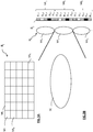
- the current full image II j is acquired conventionally using an image capture device which comprises a camera (not shown) and a lenticular network RL which is arranged between a scene SC in three dimensions and the camera .
- the lenticular network RL comprises a plurality of microlenses, of which only three microlenses ML 1 , ML 2 , ML 3 are represented on the figure 3B .
- the microlenses are all identical.
- the integral image II j is rendered on a screen (not shown) which is disposed in the focal plane of the aforementioned microlenses.
- each micro-image of the integral image II j contains several pixels of different colors, each of these pixels being representative of a given perspective of the scene SC.
- each micro-image has the same size as a microlens and therefore only three micro-images MI 1 , MI 2 and MI 3 are represented, respectively in correspondence with the three microlenses ML 1 , ML 2 , ML 3 .
- each micro-image is composed for example of five pixels of different colors. For a given micro-image MI i (1 ⁇ i ⁇ N), the latter contains five pixels P i, 1 , P i, 2 , P i, 3 , P i, 4 , P i, 5 .
- each angle of incidence corresponds to a particular viewing angle according to which an observer has the possibility of viewing the scene SC.
- the values of these angles are within the characteristic angular range of a microlens considered.
- Such an angular range corresponding, for example, to that of the microlens ML 2 , is represented in bold and solid lines on the figure 3B for illustrative purposes.
- the image capture device is configured to adapt the number of microlenses that constitute it and the resolution of the latter.
- any integral image acquired by such an image-capturing device is characterized by a given number of micro-images and a given resolution for each of these micro-images, these two numbers constituting parameters associated with the capture device. images.
- the current integral image II j is decomposed into at least one view V u from said plurality of micro-images constituting the current integral image II j and the resolution thereof.
- Step C1 is implemented by a processing software module MDCV_CO as shown in FIG. figure 2 .
- the current integral image II j is decomposed for example into a single view V 1 which contains by example the pixel placed in the center of the micro-image MI 1 , the pixel placed in the center of the micro-image MI 2 , ..., the pixel placed in the center of the micro-image MI N.
- the central pixel of each micro-image is symbolized by "x c ".
- step C2 it is proceeded to the coding of said at least one view V u .
- step C2 is implemented by a software coding module MCV_CO views as shown on the figure 2 , which module is controlled by the microprocessor .mu.P of UT_CO processing unit.
- a substep C21 for predicting said view V u is performed by known intra and / or inter prediction techniques.
- the view V u is divided into groups of pixels, for example blocks of pixels, each block being predicted with respect to at least one predictor block according to a prediction mode selected from a plurality of predetermined prediction modes. For example, in the case of HEVC encoding in the Intra prediction mode, there are thirty-five predetermined prediction modes.
- Such a predictor block is a block of pixels that has already been coded or coded and then decoded or not. Such a predictor block is stored beforehand in the buffer memory TAMP_CO of the encoder CO as represented in FIG. figure 2 .
- an optimal predictor block is obtained following a competition of said predetermined prediction modes, for example by minimizing a distortion rate criterion well known to those skilled in the art.
- the optimal predictor block is considered as an approximation of the considered block.
- Such sub-step C21 is implemented by the prediction module PRED1_CO represented on the figure 2 .
- the coding step C2 also comprises a substep C22 in which the difference between each block of the view V u and each corresponding optimal predictor block which has been selected during the sub-step is calculated. step C21.
- a plurality of residual data blocks is then obtained at the end of the substep C22, these residual blocks constituting a residual view Vr u .
- Such a sub-step C22 is implemented by the calculation module CAL1_CO represented on the figure 2 .
- the coding step C2 also comprises a substep C23 during which each block of residual data is transformed according to a conventional direct transformation operation such as, for example, a transformation of the DCT, DST or DWT type, to produce a plurality of transformed blocks which constitute the transformed view V u , designated by the reference Vt u .
- a conventional direct transformation operation such as, for example, a transformation of the DCT, DST or DWT type, to produce a plurality of transformed blocks which constitute the transformed view V u , designated by the reference Vt u .
- Such an operation is performed by the MT1_CO module represented on the figure 2 .
- the coding step C2 also comprises a sub-step C24 in which the quantization of each transformed block is carried out according to a classical quantization operation, such as, for example, scalar or vector quantization. A set Vq u of quantized coefficients is then obtained at the end of this substep.
- Such sub-step C24 is performed by means of the quantification module MQ1_CO as represented in FIG. figure 2 .
- Such a quantization sub-step is implemented using a quantization step QP 1 which is predetermined. The manner in which this parameter is determined will be described later in the description.
- Such a substep C25 entropy coding is implemented by the entropic coding module MCE1_CO shown on the figure 2 .
- the value of the quantization step QP 1 is also entropically encoded.
- the step C3 for producing such a stream is implemented by the MGF1 module for generating data streams, as represented on FIG. figure 2 .
- the signal F 1 contains the information used during the sub-step of prediction C21.
- Such information notably comprises the type of prediction (inter or intra), and if necessary, the prediction mode selected. the type of partitioning of the blocks of the view V u if the latter have been subdivided, the index of the reference view and the displacement vector used in the case where an inter prediction mode has been selected.
- Such information is coded entropically before being transmitted in the stream F 1 .
- the signal F 1 also contains the entropically coded value of the quantization step QP 1 .
- step C4 represented in FIG. figure 1 , said at least one view V u is decoded.
- step C4 is implemented by an MDV_CO views decoding software module as shown in FIG. figure 2 , which module is controlled by the microprocessor .mu.P of UT_CO processing unit.
- Such an entropy decoding sub-step C41 is implemented by the entropy decoding module MDE1_CO shown in FIG. figure 2 .
- each optimal predictor block that has been used to predict each block of the view V u is also decoded to the substep C21 of the figure 1 .
- each corresponding predictor block which is stored in the buffer memory TAMP_CO of the CO encoder of the figure 2 , is thus identified.
- Such predictor blocks are, for example, blocks of pixels which have already been decoded or not and which have been obtained in accordance with the prediction mode selected at the coding of the view V u .
- the coding step C4 also comprises a substep C42 during which the digital information obtained as a result of the substep C41 is dequantized according to a conventional dequantization operation which is the inverse operation of the quantification implemented in substep C24. A set VDq u of dequantized coefficients is then obtained at the end of this substep.
- Such substep C42 is performed by means of the dequantization module MQ1 -1 _CO as shown in FIG. figure 2 .
- Coding step C4 also comprises a substep C43 in which a transformation of the set VDq u of quantized coefficients is performed that is of type DCT -1 , DST -1 or DWT -1 .
- This transformation is the inverse operation of the transformation carried out in the substep C23.
- a plurality of decoded residual data blocks which constitute the residual decoded view V u , designated by the reference VDr u .
- Such an operation is performed by the MT1 -1 _CO module represented on the figure 2 .
- the coding step C4 also comprises a substep C44 for predicting said view V u to be decoded, by selecting the optimal predictive view consisting of the optimal predictor blocks obtained following the substep C21 mentioned above.
- Such a sub-step C44 is implemented by the prediction module PRED1 -1 _CO represented on the figure 2 .
- the coding step C4 also comprises a calculation sub-step C45, during which the decoded view VD u is constructed by adding to each of the decoded residue blocks of the decoded residual view VDr u obtained at derived from substep C43, respectively each of the corresponding predictor blocks which have been identified in substep C41 above.
- Such a sub-step C45 is implemented by the calculation module CAL1 -1 _CO represented on the figure 2 .
- a step C5 represented in FIG. figure 1 , it is proceeded to the recomposition of the current integral image II j from said at least one decoded view VD u .
- Such a step consists in applying an inverse decomposition of said decomposition of the integral image carried out in the aforementioned step C1, taking into account the resolution of said at least one view V u and its position in the current integral image II j .
- Step C5 is implemented by an MDCV -1 _CO software module for re-arrangement in views, as shown in FIG. figure 2 .
- the current recomposed integral image IIrec j consists of a single view V 1 which contains for example the pixel placed in the center of the micro-image MI 1 , the pixel placed in the center of the micro-image MI 2 , .. ., the pixel placed at the center of the micro-image MI N.
- step C6 the difference between the current integral image II j and the recomposed integral image IIrec j obtained in step C5 is calculated.
- step C6 a current residual integral image IIres j is then obtained.
- Such a step C6 is implemented by a calculation module CAL2_CO represented on the figure 2 .
- Such a current residual integral image IIres j is then considered as a two-dimensional image (2D) which undergoes 2D coding during a step C7 represented in FIG. figure 1 .
- 2D two-dimensional image
- any type of 2D coding can be applied.
- step C7 is implemented by an image coding software module MDCI, as shown in FIG. figure 2 , which module is controlled by the microprocessor .mu.P of UT_CO processing unit.
- step C7 it is proceeded to a C71 substep prediction residual of said integral image IIres j by known techniques intra prediction and / or inter.
- the residual integral image IIres j is divided into pixel groups, for instance into blocks of pixels, each block being predicted from at least one predictor block according to a prediction mode selected from a plurality of modes of predetermined prediction. For example, in the case of HEVC encoding in the Intra prediction mode, there are thirty-five predetermined prediction modes.
- Such a predictor block is a block of pixels that has already been coded or coded and then decoded or not. Such a predictor block is stored beforehand in the buffer memory TAMP_CO of the encoder CO as represented in FIG. figure 2 .
- an optimal predictor block is obtained following a competition of said predetermined prediction modes, for example by minimizing a distortion rate criterion well known to those skilled in the art.
- the optimal predictor block is considered as an approximation of the considered block.
- Such a substep C71 is implemented by the prediction module PRED2_CO represented on the figure 2 .
- the coding step C7 also comprises a substep C72 during which the difference between each block of the residual integral image IIres j is calculated and each respective optimal predictor block that has been selected during substep C71.
- a plurality of residual data blocks is then obtained at the end of the substep C72, these residual blocks constituting a residual integral image IIresr j .
- Such a substep C72 is implemented by the calculation module CAL3_CO represented on the figure 2 .
- the coding step C7 also comprises a substep C73 during which each block of residual data obtained in the substep C72 is transformed according to a conventional direct transformation operation such as, for example, a transformation of type DCT, DST or DWT, to produce a plurality of transformed blocks that constitute the transformed residual integral image, designated IIrest j .
- a conventional direct transformation operation such as, for example, a transformation of type DCT, DST or DWT, to produce a plurality of transformed blocks that constitute the transformed residual integral image, designated IIrest j .
- Such an operation is performed by the MT2_CO module represented on the figure 2 .
- the coding step C7 also comprises a substep C74 in which the quantization of each transformed block obtained in the substep C73 is performed, according to a standard quantization operation, such as for example a scalar quantization or Vector. A set IIresq u of quantized coefficients is then obtained at the end of this substep.
- Such sub-step C74 is performed by means of the quantization module MQ2_CO as represented in FIG. figure 2 .
- Such an entropy coding sub-step C75 is implemented by the entropic coding module MCE2_CO shown in FIG. figure 2 .
- the value of the quantization step QP 2 is also entropically encoded.
- the step C8 of producing such a stream is implemented by the MGF2 data flow generation module, as shown in FIG. figure 2 .
- the signal F 2 contains the information used during the prediction sub-step C71.
- Such information includes the prediction type (inter or intra), and optionally, the prediction mode selected, the type of partitioning the blocks of the residual integral image IIres j if they have been subdivided, the index of the reference integral image and the displacement vector used in the case where an inter prediction mode has been selected.
- Such information is coded entropically before being transmitted in the stream F 2 .
- the signal F 2 also contains the entropically coded value of the quantization step QP 2 .
- the data signals F 1 and F 2 are multiplexed so as to form a single signal which is transmitted to the decoder DO.
- the data signals F 1 and F 2 could be transmitted separately to the decoder DO.
- the resolution parameter of the micro-images of the current integral image II j is entropy coded either during the entropic coding sub-step C25, or during the entropy coding sub-step C75.
- the resolution parameter of the micro-images is inserted either in the data signal F 1 or in the data signal F 2 , or in another data signal (not shown) which can be transmitted separately to the decoder DO or else multiplexed with the data signals F 1 and F 2 .
- the number of views and the position of the latter are selected as those that optimize a predetermined coding performance criterion.
- the number and position of the views are selected by minimizing, for example, a distortion rate criterion well known to those skilled in the art that is applied to the coding step C2 and to the coding step C7.
- the number and position of the views are selected as those which minimize the number of data associated with the residual integral image IIres j obtained at the end of step C6 in figure 1 .
- the number and position of the views that have been selected are transmitted or not to the decoder DO.
- the value of the quantization step QP 1 used during the quantization sub-step C24 and the quantization step value QP 2 used during the quantization sub-step C74 are selected as optimizing a predetermined coding performance criterion.
- the quantization steps QP 1 and QP 2 are each selected by minimization, for example, of a distortion flow criterion well known to those skilled in the art which is applied to the coding step C2 and to the coding step C7.
- only said CI2 processing step is applied because it provides a reconstruction of the current integral image II j which is the most effective.
- transformation steps CI1, CI2 and CI3 are respectively implemented by transformation software modules TR1_CO, TR2_CO and TR3_CO, as represented in dotted line on the figure 2 .
- Each of the transformation steps CI1, CI2 and CI3 uses a corresponding transformation parameter Ptr 1 , Ptr 2 , Ptr 3 .
- the transformation parameters Ptr 1 , Ptr 2 , Ptr 3 are selected as being those which optimize a predetermined coding performance criterion.
- the latter are selected by minimizing, for example, a distortion rate criterion well known to those skilled in the art that is applied to the coding step C2 and to the coding step C7.
- the transformation parameters Ptr 1 , Ptr 2 , Ptr 3 are selected as being those which minimize the number of data associated with the residual integral image IIres j obtained at the end of step C6 in figure 1 .
- the transformation parameters Ptr 1 , Ptr 2 , Ptr 3 are transmitted or not to the decoder DO.
- An example of possible transformation is smoothing.
- the parameter associated with this transformation corresponds to the size in pixels of the smoothing filter applied to the image.
- the recomposed integral image IIrec j then contains details that do not correspond to the details of the current original integral image II j .
- a geometrical transformation (expansion, erosion, rotation, symmetry, etc.) could be applied to the said at least one view V u and / or to the said at least one reconstructed view VD u and / or to reconstituted integral image IIrec j .
- the decoding method according to the invention is represented in the form of an algorithm comprising steps D1 to D5 as represented in FIG. figure 6 .
- the decoder DO comprises a memory MEM_DO comprising a buffer memory TAMP_DO, a processing unit UT_DO equipped for example with a microprocessor ⁇ P and driven by a computer program PG_DO which implements the decoding method according to the invention.
- the code instructions of the computer program PG_DO are for example loaded into a RAM memory before being executed by the processor of the processing unit UT_DO.
- the decoding method shown in the figure 6 applies to any current integral image II j fixed to be decoded or part of a sequence of integral images II 1 , ..., II j , ..., II M ( 1 j j M M ) to be decoded .
- information representative of the current integral image decoding j II are identified in the data signal F received at the decoder, as issued following the coding method of the figure 1 .
- the identification steps D1a) and D1b) are implemented by a signal analysis module MI_DO, as represented in FIG. figure 5 , said module being driven by the microprocessor ⁇ P of the processing unit UT_DO.
- step D1a following step D1a), during a step D2 shown in FIG. figure 6 , at decoding said at least one view V u encoded entropically.
- step D2 is implemented by a view decoding software module MDV_DO as shown in FIG. figure 5 , which module is controlled by the microprocessor .mu.P of UT_DO processing unit.
- Such an entropy decoding substep D21 is implemented by the entropy decoding module MDE1_DO shown in FIG. figure 5 .
- each corresponding predictor block which is stored in the buffer TAMP_DO of the decoder DO of the figure 5 , is thus identified.
- Such predictor blocks are for example blocks of pixels which have already been decoded or not and which have been obtained according to the prediction mode selected in the coding of the view V u .
- the decoding step D2 also comprises a substep D22 during which the digital information obtained as a result of the subprocessing is decoded using the value of the quantization parameter QP 1 decoded entropically.
- step D21 according to a conventional dequantization operation which is the inverse operation of the quantization implemented during the quantization sub-step C24 of FIG. figure 1 .
- a set VDq u of dequantized coefficients is then obtained at the end of the substep D22.
- Such a sub-step D22 is performed by means of the quantization module MQ1 -1 _DO, as represented in FIG. figure 5 .
- the decoding step D2 also comprises a substep D23 during which a transformation of the set VDq u of quantized coefficients is performed which is of type DCT -1 , DST -1 or DWT -1 .
- This transformation is the inverse operation of the transformation carried out in substep C23 of the figure 1 .
- a plurality of decoded residual data blocks are obtained which constitute the residual decoded view V u , denoted by the reference VDr u .
- Such an operation is performed by the MT1 -1 _DO module represented on the figure 5 .
- the decoding step D2 also comprises a substep D24 for predicting said view V u to be decoded, by selecting the optimal predictive view consisting of the optimal predictor blocks obtained following the substep D21 mentioned above.
- Such a substep D24 is implemented by the prediction module PRED1 -1 _DO shown in FIG. figure 5 .
- the decoding step D2 also comprises a calculation sub-step D25, during which the decoded view VD u is constructed by adding to each of the decoded residue blocks of the decoded residual view VDr u obtained at the end of the decoded view. from substep D23, respectively each of the corresponding predictor blocks which have been identified in substep D21 above.
- Such a substep D25 is implemented by the calculation module CAL1 -1 _DO shown in FIG. figure 5 .
- step D3 it is proceeded to the recomposition of the current integral image II j from said at least one decoded view VD u .
- One such step is to apply a decomposition inverse of said decomposition of the integral image carried out at the coding step C1 of the figure 1 , taking into account the value of the resolution parameter p rs1 which has been decoded entropically in step D21 and the position of the said at least one view in the current integral image II j .
- step D3 a decoded reconstructed integral image is obtained which is denoted IIDrec j on the figure 6 .
- the step D3 is implemented by a software module MDCV -1 _DO of reconstruction in views, as represented on the figure 5 , said module being driven by the microprocessor ⁇ P of the processing unit UT_DO.
- the integral image II j to be decoded is then blended in one or more views, as shown in the examples of Figures 4A and 4B .
- step D1b following step D1b), during a step D4 shown in FIG. figure 6 , Decoding in two dimensions of the current residual integral image IIres j which has been coded in step C4 shown in figure 1 .
- the type of 2D decoding performed is in accordance with the type of 2D coding implemented in step C7 of FIG. figure 1 .
- step D4 is implemented by an image decoding software module MDDI, as shown in FIG. figure 5 , which module is controlled by the microprocessor .mu.P of UT_DO processing unit.
- Such an entropy decoding sub-step D41 is implemented by the entropy decoding module MDE2_DO shown in FIG. figure 5 .
- each optimal predictor block which has been used to predict each block of the current residual integral image IIres j during the substep C71 of the present invention is also decoded. figure 1 .
- each corresponding predictor block which is stored in the buffer TAMP_DO of the decoder DO of the figure 5 , is thus identified.
- Such predictor blocks are, for example, blocks of pixels which have already been decoded or not and which have been obtained in accordance with the prediction mode selected in the coding of the current residual integral image IIres j .
- the decoding step D4 also comprises a substep D42 during which dequantization, using the value of the quantization parameter QP 2 decoded entropically, the digital information obtained as a result of the sub-step D42.
- step D41 according to a conventional operation of dequantization which is the inverse operation of the quantization implemented during the quantization sub-step C74 of FIG. figure 1 .
- a set IIDresq j dequantized coefficient is then obtained after D42 sub-step.
- Such a sub-step D42 is performed by means of the quantization module MQ2 -1 _DO, as represented in FIG. figure 5 .
- the decoding step D4 also comprises a substep D43 during which a transformation of the set IIDresq j of quantized coefficients which is of type DCT -1 , DST -1 or DWT -1 is carried out .
- This transformation is the inverse operation of the transformation carried out in the substep C73 of the figure 1 .
- a plurality of decoded residual data blocks are obtained which constitute the decoded residual integral image, designated by the reference IIDresr j .
- Such an operation is performed by the MT2 -1 _DO module represented on the figure 5 .
- the D4 decoding step further comprises a substep D44 prediction residual of said integral image IIres j to be decoded, by selection of the residual integral image consisting optimal predictor optimal predictor blocks obtained as a result of the substep D41 supra.
- Such a sub-step D44 is implemented by the prediction module PRED2 -1 _DO represented on the figure 5 .
- the decoding step D4 also comprises a calculation sub-step D45, during which the decoded residual integral image IIDres j is constructed by adding to each of the decoded residue blocks of the decoded residual integral image. IIDresr j obtained at the end of substep D43, respectively each of the corresponding predictor blocks that have been identified in substep D41 supra.
- Such a sub-step D45 is implemented by the calculation module CAL2 -1 _DO shown in FIG. figure 5 .
- step D5 a current decoded integral image IID j is then obtained.
- Such a step D5 is implemented by a calculation software module CAL3 -1 _DO represented on the figure 5 .
- transformation steps DI1, DI2, DI3 are respectively implemented by transformation software modules TR1_DO, TR2_DO and TR3_DO, as represented in dashed line on the figure 5 .
- Each of the transformation steps DI1, DI2 and DI3 uses a corresponding transformation parameter Ptr 1 , Ptr 2 , Ptr 3 .
Landscapes
- Engineering & Computer Science (AREA)
- Multimedia (AREA)
- Signal Processing (AREA)
- Compression Or Coding Systems Of Tv Signals (AREA)
Claims (15)
- Verfahren zur Codierung mindestens eines aktuellen integralen Bildes (IIj), das von einer Bilderfassungsvorrichtung erfasst wird, umfassend die folgenden Schritte:- Zerlegen (C1) des aktuellen integralen Bildes in mindestens eine Ansicht (Vu), die eine gegebene Perspektive einer Szene darstellt, und auf Basis von mindestens einem Bilderfassungsparameter, der der Bilderfassungsvorrichtung zugeordnet ist,- Codieren (C2) der mindestens einen Ansicht,- Decodieren (C4) der mindestens einen Ansicht,- neuerliches Zusammenstellen (C5) des aktuellen integralen Bildes auf Basis der mindestens einen decodierten Ansicht durch Anwendung einer inversen Zerlegung der Zerlegung des integralen Bildes und auf Basis des mindestens einen Bilderfassungsparameters, der der Bilderfassungsvorrichtung zugeordnet ist,dadurch gekennzeichnet, dass das Verfahren auch die folgenden Schritte umfasst:- Bestimmen (C6) eines integralen Restbildes (IIresj) durch Vergleich des mindestens einen aktuellen integralen Bildes mit dem wieder zusammengestellten integralen Bild,- Codieren (C7) der dem integralen Restbild zugeordneten Daten und des mindestens einen Bilderfassungsparameters, der der Bilderfassungsvorrichtung zugeordnet ist.
- Codierungsverfahren nach Anspruch 1, umfassend:- einen Schritt (C3) der Ausarbeitung eines ersten Datensignals (F1), das aus der Codierung der mindestens einen Ansicht stammende Daten enthält,- einen Schritt (C8) der Ausarbeitung eines zweiten Datensignals (F2), das die dem codierten integralen Restbild zugeordneten Daten enthält,wobei der mindestens eine Bilderfassungsparameter, der der Bilderfassungsvorrichtung zugeordnet ist, entweder in dem ersten Signal oder in dem zweiten Signal oder in einem anderen auszuarbeitenden Datensignal enthalten ist.
- Codierungsverfahren nach Anspruch 1 oder Anspruch 2, während dessen die Anzahl und die Position der zu codierenden Ansichten des aktuellen integralen Bildes derart ausgewählt werden, dass sie ein vorbestimmtes Codierungsleistungskriterium optimieren.
- Codierungsverfahren nach Anspruch 3, während dessen die Anzahl und die Position der Ansichten des aktuellen integralen Bildes derart ausgewählt werden, dass sie die Anzahl von dem integralen Restbild zugeordneten Daten minimieren.
- Codierungsverfahren nach Anspruch 1 oder Anspruch 2, während dessen eine Auswahl eines Werts eines ersten Quantifizierungsparameters (QP1), der während des Codierungsschritts (C2) der mindestens einen Ansicht anzuwenden ist, und eine Auswahl eines Werts eines zweiten Quantifizierungsparameters (QP2) vorgenommen wird, der während des Codierungsschritts (C7) der dem integralen Restbild zugeordneten Daten anzuwenden ist, wobei die Werte derart gewählt sind, dass sie ein vorbestimmtes Codierungsleistungskriterium optimieren.
- Codierungsverfahren nach einem der Ansprüche 1 bis 5, ferner umfassend einen Schritt (CI1; CI2; CI3) der Änderung eines Bildes, der angewandt wird:- zwischen dem Schritt (C1) der Zerlegung des aktuellen integralen Bildes in die mindestens eine Ansicht und dem Schritt (C2) der Codierung der mindestens einen Ansicht, und/oder- zwischen dem Schritt (C4) der Decodierung der mindestens einen Ansicht und dem Schritt (C5) der neuerlichen Zusammenstellung des aktuellen integralen Bildes, und/oder- zwischen dem Schritt (C5) der neuerlichen Zusammenstellung des aktuellen integralen Bildes und dem Schritt (C6) der Bestimmung des integralen Restbildes.
- Codierungsverfahren nach Anspruch 6, während dessen der Änderungsschritt mit Hilfe eines Änderungsparameters (ptr1; ptr2; ptr3) eingesetzt wird, der derart gewählt ist, dass ein vorbestimmtes Codierungsleistungskriterium optimiert oder auch, dass die Anzahl von dem integralen Restbild zugeordneten Daten minimiert wird.
- Vorrichtung zur Codierung mindestens eines aktuellen integralen Bildes (IIj), das von einer Bilderfassungsvorrichtung erfasst wird, umfassend:- erste Bearbeitungsmittel (MDCV_CO) zum Zerlegen des aktuellen integralen Bildes in mindestens eine Ansicht, die eine gegebene Perspektive einer Szene darstellt, und auf Basis von mindestens einem Bilderfassungsparameter, der der Bilderfassungsvorrichtung zugeordnet ist,- erste Mittel (MCV_CO) zum Codieren der mindestens einen Ansicht,- Mittel (MDV_CO) zum Decodieren der mindestens einen Ansicht,- zweite Bearbeitungsmittel (MDCV-1_CO) zum neuerlichen Zusammenstellen des aktuellen integralen Bildes auf Basis der decodierten Ansicht durch Anwendung einer inversen Zerlegung der Zerlegung des integralen Bildes und auf Basis des mindestens einen Bilderfassungsparameters, der der Bilderfassungsvorrichtung zugeordnet ist,dadurch gekennzeichnet, dass die Vorrichtung auch umfasst:- Berechnungsmittel (CAL2_CO) zum Bestimmen eines integralen Restbildes durch Vergleich des mindestens einen aktuellen integralen Bildes mit dem wieder zusammengestellten integralen Bild,- zweite Codierungsmittel (MDCI) zum Codieren der dem integralen Restbild zugeordneten Daten und des mindestens einen Bilderfassungsparameters, der der Bilderfassungsvorrichtung zugeordnet ist.
- Computerprogramm, umfassend Anweisungen, die das Codierungsverfahren nach einem der Ansprüche 1 bis 7 implementieren, wenn es auf einem Computer ausgeführt wird.
- Verfahren zur Decodierung eines Datensignals (F), das für mindestens ein aktuelles integrales Bild (IIj) repräsentativ ist, das von einer Bilderfassungsvorrichtung erfasst und vorher codiert wurde, wobei das Verfahren die folgenden Schritte umfasst:- in dem Datensignal Identifikation (D1a) mindestens eines Bilderfassungsparameters, der der Bilderfassungsvorrichtung zugeordnet ist,- Decodieren (D2) mindestens einer Ansicht des aktuellen integralen Bildes auf Basis des mindestens einen identifizierten Bilderfassungsparameters, wobei die mindestens eine Ansicht eine gegebene Perspektive einer Szene darstellt,- neuerliches Zusammenstellen (D3) eines integralen Bildes als Prädiktor eines aktuellen integralen Bildes auf Basis der mindestens einen decodierten Ansicht und auf Basis des mindestens einen Bilderfassungsparameters, der der Bilderfassungsvorrichtung zugeordnet ist,dadurch gekennzeichnet, dass das Verfahren auch die folgenden Schritte umfasst:- Decodieren (D4) der codierten Daten, die für den Unterschied zwischen dem mindestens einen aktuellen integralen Bild und dem neuerlich zusammengestellten integralen Bild repräsentativ sind,- Rekonstruieren (D5) des aktuellen integralen Bildes auf Basis des neuerlich zusammengestellten integralen Bildes und der für den Unterschied repräsentativen decodierten Daten.
- Decodierungsverfahren nach Anspruch 10, während dessen der Schritt des neuerlichen Zusammenstellens des aktuellen integralen Bildes mit Hilfe eines Positionsparameters der mindestens einen decodierten Ansicht in dem zu decodierenden aktuellen integralen Bild eingesetzt wird, wobei der Positionsparameter vorbestimmt ist oder auch aus dem Datensignal abgelesen wird.
- Decodierungsverfahren nach Anspruch 10 oder Anspruch 11, während dessen:- der Schritt der Decodierung der mindestens einen Ansicht den Einsatz eines Schrittes (D22) der Dequantifizierung auf Basis eines ersten Quantifizierungsparameters, dessen Wert in dem Datensignal identifiziert wird, umfasst,- der Schritt der Decodierung der codierten Daten, die für den Unterschied zwischen dem mindestens einen aktuellen integralen Bild und dem neuerlich zusammengestellten integralen Bild repräsentativ sind, den Einsatz eines Schrittes (D42) der Dequantifizierung auf Basis eines zweiten Quantifizierungsparameters, dessen Wert in dem Datensignal identifiziert wird, umfasst.
- Decodierungsverfahren nach einem der Ansprüche 10 bis 12, ferner umfassend einen Schritt (DI1; DI2; DI3) der Änderung eines Bildes auf Basis eines vorbestimmten oder auch aus dem Datensignal abgelesenen Änderungsparameters, wobei der Änderungsschritt angewandt wird:- zwischen dem Schritt (D2) der Decodierung der mindestens einen Ansicht und dem Schritt (D3) der neuerlichen Zusammenstellung des aktuellen integralen Bildes als Prädiktor des aktuellen integralen Bildes, und/oder- zwischen dem Schritt (D3) der neuerlichen Zusammenstellung des aktuellen integralen Bildes als Prädiktor des aktuellen integralen Bildes und dem Schritt (D4) der Rekonstruktion des aktuellen integralen Bildes.
- Vorrichtung (DO) zur Decodierung eines Datensignals, das für mindestens ein aktuelles integrales Bild (IIj) repräsentativ ist, das von einer Bilderfassungsvorrichtung erfasst und vorher codiert wurde, wobei die Decodierungsvorrichtung umfasst:- Analysemittel (MI_DO) zur Identifikation mindestens eines Bilderfassungsparameters, der der Bilderfassungsvorrichtung zugeordnet ist, in dem Datensignal,- erste Decodierungsmittel (MDV_DO) zum Decodieren mindestens einer Ansicht des aktuellen integralen Bildes auf Basis des mindestens einen identifizierten Bilderfassungsparameters, wobei die mindestens eine Ansicht eine gegebene Perspektive einer Szene darstellt,- Bearbeitungsmittel (MDCV-1_DO) zum neuerlichen Zusammenstellen eines integralen Bildes als Prädiktor eines aktuellen integralen Bildes auf Basis der mindestens einen decodierten Ansicht und auf Basis des mindestens einen Bilderfassungsparameters, der der Bilderfassungsvorrichtung zugeordnet ist,dadurch gekennzeichnet, dass die Vorrichtung auch umfasst:- zweite Decodierungsmittel (MDDI) zum Decodieren der codierten Daten, die für den Unterschied zwischen dem mindestens einen aktuellen integralen Bild und dem neuerlich zusammengestellten integralen Bild repräsentativ sind,- Rekonstruktionsmittel (CAL3-1_DO) zum Rekonstruieren des aktuellen integralen Bildes auf Basis des neuerlich zusammengestellten integralen Bildes und der für den Unterschied repräsentativen decodierten Daten.
- Computerprogramm, umfassend Anweisungen, die das Decodierungsverfahren nach einem der Ansprüche 10 bis 13 implementieren, wenn es auf einem Computer ausgeführt wird.
Applications Claiming Priority (2)
| Application Number | Priority Date | Filing Date | Title |
|---|---|---|---|
| FR1458918A FR3026261A1 (fr) | 2014-09-22 | 2014-09-22 | Procede de codage et de decodage d'images integrales, dispositif de codage et de decodage d'images integrales et programmes d'ordinateur correspondants |
| PCT/FR2015/052525 WO2016046483A1 (fr) | 2014-09-22 | 2015-09-21 | Génération et codage d'images intégrales résiduelles |
Publications (2)
| Publication Number | Publication Date |
|---|---|
| EP3198876A1 EP3198876A1 (de) | 2017-08-02 |
| EP3198876B1 true EP3198876B1 (de) | 2019-05-22 |
Family
ID=52102808
Family Applications (1)
| Application Number | Title | Priority Date | Filing Date |
|---|---|---|---|
| EP15778371.3A Active EP3198876B1 (de) | 2014-09-22 | 2015-09-21 | Erzeugung und codierung von integralen restbildern |
Country Status (6)
| Country | Link |
|---|---|
| US (1) | US10630973B2 (de) |
| EP (1) | EP3198876B1 (de) |
| CN (1) | CN107079168B (de) |
| ES (1) | ES2736115T3 (de) |
| FR (1) | FR3026261A1 (de) |
| WO (1) | WO2016046483A1 (de) |
Families Citing this family (4)
| Publication number | Priority date | Publication date | Assignee | Title |
|---|---|---|---|---|
| US10067093B2 (en) * | 2013-07-01 | 2018-09-04 | Richard S. Goldhor | Decomposing data signals into independent additive terms using reference signals |
| US10540992B2 (en) | 2012-06-29 | 2020-01-21 | Richard S. Goldhor | Deflation and decomposition of data signals using reference signals |
| US10473628B2 (en) | 2012-06-29 | 2019-11-12 | Speech Technology & Applied Research Corporation | Signal source separation partially based on non-sensor information |
| CN110097497B (zh) * | 2019-05-14 | 2023-03-24 | 电子科技大学 | 基于residual multismoothlets的多尺度图像变换和逆变换方法 |
Family Cites Families (6)
| Publication number | Priority date | Publication date | Assignee | Title |
|---|---|---|---|---|
| US6476805B1 (en) * | 1999-12-23 | 2002-11-05 | Microsoft Corporation | Techniques for spatial displacement estimation and multi-resolution operations on light fields |
| FR2974966A1 (fr) * | 2011-05-05 | 2012-11-09 | France Telecom | Procede de codage et de decodage d'images integrales, dispositif de codage et de decodage d'images integrales et programmes d'ordinateur correspondants |
| WO2013009716A2 (en) * | 2011-07-08 | 2013-01-17 | Dolby Laboratories Licensing Corporation | Hybrid encoding and decoding methods for single and multiple layered video coding systems |
| FR2989805A1 (fr) | 2012-04-19 | 2013-10-25 | France Telecom | Procede de codage et de decodage d'images integrales, dispositif de codage et de decodage d'images integrales et programmes d'ordinateur correspondants |
| EP2898689B1 (de) * | 2012-09-21 | 2020-05-06 | Nokia Technologies Oy | Verfahren und vorrichtung zur videocodierung |
| US10244223B2 (en) * | 2014-01-10 | 2019-03-26 | Ostendo Technologies, Inc. | Methods for full parallax compressed light field 3D imaging systems |
-
2014
- 2014-09-22 FR FR1458918A patent/FR3026261A1/fr not_active Withdrawn
-
2015
- 2015-09-21 US US15/501,172 patent/US10630973B2/en active Active
- 2015-09-21 ES ES15778371T patent/ES2736115T3/es active Active
- 2015-09-21 WO PCT/FR2015/052525 patent/WO2016046483A1/fr active Application Filing
- 2015-09-21 CN CN201580050480.5A patent/CN107079168B/zh active Active
- 2015-09-21 EP EP15778371.3A patent/EP3198876B1/de active Active
Non-Patent Citations (1)
| Title |
|---|
| None * |
Also Published As
| Publication number | Publication date |
|---|---|
| ES2736115T3 (es) | 2019-12-26 |
| WO2016046483A1 (fr) | 2016-03-31 |
| US10630973B2 (en) | 2020-04-21 |
| CN107079168B (zh) | 2020-03-24 |
| FR3026261A1 (fr) | 2016-03-25 |
| US20170230654A1 (en) | 2017-08-10 |
| EP3198876A1 (de) | 2017-08-02 |
| CN107079168A (zh) | 2017-08-18 |
Similar Documents
| Publication | Publication Date | Title |
|---|---|---|
| EP3209021B1 (de) | Aufzeichnungsmedium zur speicherung von kodierten bilddaten | |
| EP3061246B1 (de) | Verfahren zur codierung und decodierung von bildern, vorrichtung zur codierung und decodierung von bildern und entsprechende computerprogramme | |
| EP3490258A1 (de) | Methode und aufzeichnungsmedium zur speicherung von kodierten bilddaten | |
| EP2705666B1 (de) | Verfahren zur codierung und decodierung zusammengesetzte bilder, vorrichtung zur kodierung und dekodierung zusammengesetzte bilder und entsprechende computerprogramme | |
| EP3198876B1 (de) | Erzeugung und codierung von integralen restbildern | |
| WO2015055937A1 (fr) | Procédé de codage et de décodage d'images, dispositif de codage et de décodage d'images et programmes d'ordinateur correspondants | |
| WO2017037368A2 (fr) | Procédé de codage et de décodage d'images, dispositif de codage et de décodage d'images et programmes d'ordinateur correspondants | |
| EP2716045B1 (de) | Verfahren, vorrichtung und computerprogramme zur enkodierung und dekodierung von bildern | |
| EP2761871B1 (de) | Dekoder-seitige bewegungschätzung durch mustervergleich | |
| EP3180914A1 (de) | Bildcodierungs- und decodierungsverfahren, bildcodierungs- und decodierungsvorrichtung sowie entsprechende computerprogramme | |
| WO2018073523A1 (fr) | Procédé de codage et de décodage de paramètres d'image, dispositif de codage et de décodage de paramètres d'image et programmes d'ordinateur correspondants | |
| EP2901698A1 (de) | Verfahren zur codierung und decodierung von bildern, codierungs- und decodierungsvorrichtung und damit zusammenhängende computerprogramme | |
| WO2017129880A1 (fr) | Procédé de codage et décodage de données, dispositif de codage et décodage de données et programmes d'ordinateur correspondants | |
| EP3360328A1 (de) | Mehrfachansichtscodierung und -decodierung | |
| EP3918798A1 (de) | Verfahren und vorrichtung zur codierung und decodierung von daten im zusammenhang mit einer videosequenz | |
| WO2019008253A1 (fr) | Procédé de codage et décodage d'images, dispositif de codage et décodage et programmes d'ordinateur correspondants | |
| WO2021160955A1 (fr) | Procédé et dispositif de traitement de données de vidéo multi-vues | |
| EP2839648A1 (de) | Verfahren zur codierung und decodierung ganzheitlicher bilder, vorrichtung zur codierung und decodierung ganzheitlicher bilder und zugehörige computerprogramme |
Legal Events
| Date | Code | Title | Description |
|---|---|---|---|
| STAA | Information on the status of an ep patent application or granted ep patent |
Free format text: STATUS: THE INTERNATIONAL PUBLICATION HAS BEEN MADE |
|
| PUAI | Public reference made under article 153(3) epc to a published international application that has entered the european phase |
Free format text: ORIGINAL CODE: 0009012 |
|
| STAA | Information on the status of an ep patent application or granted ep patent |
Free format text: STATUS: REQUEST FOR EXAMINATION WAS MADE |
|
| 17P | Request for examination filed |
Effective date: 20170407 |
|
| AK | Designated contracting states |
Kind code of ref document: A1 Designated state(s): AL AT BE BG CH CY CZ DE DK EE ES FI FR GB GR HR HU IE IS IT LI LT LU LV MC MK MT NL NO PL PT RO RS SE SI SK SM TR |
|
| AX | Request for extension of the european patent |
Extension state: BA ME |
|
| RIN1 | Information on inventor provided before grant (corrected) |
Inventor name: DRICOT, ANTOINE Inventor name: JUNG, JOEL |
|
| DAV | Request for validation of the european patent (deleted) | ||
| DAX | Request for extension of the european patent (deleted) | ||
| GRAP | Despatch of communication of intention to grant a patent |
Free format text: ORIGINAL CODE: EPIDOSNIGR1 |
|
| STAA | Information on the status of an ep patent application or granted ep patent |
Free format text: STATUS: GRANT OF PATENT IS INTENDED |
|
| INTG | Intention to grant announced |
Effective date: 20190129 |
|
| GRAS | Grant fee paid |
Free format text: ORIGINAL CODE: EPIDOSNIGR3 |
|
| GRAA | (expected) grant |
Free format text: ORIGINAL CODE: 0009210 |
|
| STAA | Information on the status of an ep patent application or granted ep patent |
Free format text: STATUS: THE PATENT HAS BEEN GRANTED |
|
| AK | Designated contracting states |
Kind code of ref document: B1 Designated state(s): AL AT BE BG CH CY CZ DE DK EE ES FI FR GB GR HR HU IE IS IT LI LT LU LV MC MK MT NL NO PL PT RO RS SE SI SK SM TR |
|
| REG | Reference to a national code |
Ref country code: GB Ref legal event code: FG4D Free format text: NOT ENGLISH |
|
| REG | Reference to a national code |
Ref country code: CH Ref legal event code: EP |
|
| REG | Reference to a national code |
Ref country code: IE Ref legal event code: FG4D Free format text: LANGUAGE OF EP DOCUMENT: FRENCH |
|
| REG | Reference to a national code |
Ref country code: AT Ref legal event code: REF Ref document number: 1137524 Country of ref document: AT Kind code of ref document: T Effective date: 20190615 |
|
| REG | Reference to a national code |
Ref country code: DE Ref legal event code: R096 Ref document number: 602015030838 Country of ref document: DE |
|
| REG | Reference to a national code |
Ref country code: NL Ref legal event code: MP Effective date: 20190522 |
|
| REG | Reference to a national code |
Ref country code: LT Ref legal event code: MG4D |
|
| PG25 | Lapsed in a contracting state [announced via postgrant information from national office to epo] |
Ref country code: LT Free format text: LAPSE BECAUSE OF FAILURE TO SUBMIT A TRANSLATION OF THE DESCRIPTION OR TO PAY THE FEE WITHIN THE PRESCRIBED TIME-LIMIT Effective date: 20190522 Ref country code: HR Free format text: LAPSE BECAUSE OF FAILURE TO SUBMIT A TRANSLATION OF THE DESCRIPTION OR TO PAY THE FEE WITHIN THE PRESCRIBED TIME-LIMIT Effective date: 20190522 Ref country code: NL Free format text: LAPSE BECAUSE OF FAILURE TO SUBMIT A TRANSLATION OF THE DESCRIPTION OR TO PAY THE FEE WITHIN THE PRESCRIBED TIME-LIMIT Effective date: 20190522 Ref country code: SE Free format text: LAPSE BECAUSE OF FAILURE TO SUBMIT A TRANSLATION OF THE DESCRIPTION OR TO PAY THE FEE WITHIN THE PRESCRIBED TIME-LIMIT Effective date: 20190522 Ref country code: NO Free format text: LAPSE BECAUSE OF FAILURE TO SUBMIT A TRANSLATION OF THE DESCRIPTION OR TO PAY THE FEE WITHIN THE PRESCRIBED TIME-LIMIT Effective date: 20190822 Ref country code: AL Free format text: LAPSE BECAUSE OF FAILURE TO SUBMIT A TRANSLATION OF THE DESCRIPTION OR TO PAY THE FEE WITHIN THE PRESCRIBED TIME-LIMIT Effective date: 20190522 Ref country code: PT Free format text: LAPSE BECAUSE OF FAILURE TO SUBMIT A TRANSLATION OF THE DESCRIPTION OR TO PAY THE FEE WITHIN THE PRESCRIBED TIME-LIMIT Effective date: 20190922 Ref country code: FI Free format text: LAPSE BECAUSE OF FAILURE TO SUBMIT A TRANSLATION OF THE DESCRIPTION OR TO PAY THE FEE WITHIN THE PRESCRIBED TIME-LIMIT Effective date: 20190522 |
|
| PG25 | Lapsed in a contracting state [announced via postgrant information from national office to epo] |
Ref country code: BG Free format text: LAPSE BECAUSE OF FAILURE TO SUBMIT A TRANSLATION OF THE DESCRIPTION OR TO PAY THE FEE WITHIN THE PRESCRIBED TIME-LIMIT Effective date: 20190822 Ref country code: GR Free format text: LAPSE BECAUSE OF FAILURE TO SUBMIT A TRANSLATION OF THE DESCRIPTION OR TO PAY THE FEE WITHIN THE PRESCRIBED TIME-LIMIT Effective date: 20190823 Ref country code: RS Free format text: LAPSE BECAUSE OF FAILURE TO SUBMIT A TRANSLATION OF THE DESCRIPTION OR TO PAY THE FEE WITHIN THE PRESCRIBED TIME-LIMIT Effective date: 20190522 Ref country code: LV Free format text: LAPSE BECAUSE OF FAILURE TO SUBMIT A TRANSLATION OF THE DESCRIPTION OR TO PAY THE FEE WITHIN THE PRESCRIBED TIME-LIMIT Effective date: 20190522 |
|
| REG | Reference to a national code |
Ref country code: AT Ref legal event code: MK05 Ref document number: 1137524 Country of ref document: AT Kind code of ref document: T Effective date: 20190522 |
|
| PG25 | Lapsed in a contracting state [announced via postgrant information from national office to epo] |
Ref country code: EE Free format text: LAPSE BECAUSE OF FAILURE TO SUBMIT A TRANSLATION OF THE DESCRIPTION OR TO PAY THE FEE WITHIN THE PRESCRIBED TIME-LIMIT Effective date: 20190522 Ref country code: DK Free format text: LAPSE BECAUSE OF FAILURE TO SUBMIT A TRANSLATION OF THE DESCRIPTION OR TO PAY THE FEE WITHIN THE PRESCRIBED TIME-LIMIT Effective date: 20190522 Ref country code: SK Free format text: LAPSE BECAUSE OF FAILURE TO SUBMIT A TRANSLATION OF THE DESCRIPTION OR TO PAY THE FEE WITHIN THE PRESCRIBED TIME-LIMIT Effective date: 20190522 Ref country code: RO Free format text: LAPSE BECAUSE OF FAILURE TO SUBMIT A TRANSLATION OF THE DESCRIPTION OR TO PAY THE FEE WITHIN THE PRESCRIBED TIME-LIMIT Effective date: 20190522 Ref country code: CZ Free format text: LAPSE BECAUSE OF FAILURE TO SUBMIT A TRANSLATION OF THE DESCRIPTION OR TO PAY THE FEE WITHIN THE PRESCRIBED TIME-LIMIT Effective date: 20190522 Ref country code: AT Free format text: LAPSE BECAUSE OF FAILURE TO SUBMIT A TRANSLATION OF THE DESCRIPTION OR TO PAY THE FEE WITHIN THE PRESCRIBED TIME-LIMIT Effective date: 20190522 |
|
| REG | Reference to a national code |
Ref country code: DE Ref legal event code: R097 Ref document number: 602015030838 Country of ref document: DE |
|
| PG25 | Lapsed in a contracting state [announced via postgrant information from national office to epo] |
Ref country code: SM Free format text: LAPSE BECAUSE OF FAILURE TO SUBMIT A TRANSLATION OF THE DESCRIPTION OR TO PAY THE FEE WITHIN THE PRESCRIBED TIME-LIMIT Effective date: 20190522 |
|
| PLBE | No opposition filed within time limit |
Free format text: ORIGINAL CODE: 0009261 |
|
| STAA | Information on the status of an ep patent application or granted ep patent |
Free format text: STATUS: NO OPPOSITION FILED WITHIN TIME LIMIT |
|
| PG25 | Lapsed in a contracting state [announced via postgrant information from national office to epo] |
Ref country code: TR Free format text: LAPSE BECAUSE OF FAILURE TO SUBMIT A TRANSLATION OF THE DESCRIPTION OR TO PAY THE FEE WITHIN THE PRESCRIBED TIME-LIMIT Effective date: 20190522 |
|
| 26N | No opposition filed |
Effective date: 20200225 |
|
| PG25 | Lapsed in a contracting state [announced via postgrant information from national office to epo] |
Ref country code: PL Free format text: LAPSE BECAUSE OF FAILURE TO SUBMIT A TRANSLATION OF THE DESCRIPTION OR TO PAY THE FEE WITHIN THE PRESCRIBED TIME-LIMIT Effective date: 20190522 |
|
| PG25 | Lapsed in a contracting state [announced via postgrant information from national office to epo] |
Ref country code: SI Free format text: LAPSE BECAUSE OF FAILURE TO SUBMIT A TRANSLATION OF THE DESCRIPTION OR TO PAY THE FEE WITHIN THE PRESCRIBED TIME-LIMIT Effective date: 20190522 Ref country code: MC Free format text: LAPSE BECAUSE OF FAILURE TO SUBMIT A TRANSLATION OF THE DESCRIPTION OR TO PAY THE FEE WITHIN THE PRESCRIBED TIME-LIMIT Effective date: 20190522 |
|
| REG | Reference to a national code |
Ref country code: CH Ref legal event code: PL |
|
| PG25 | Lapsed in a contracting state [announced via postgrant information from national office to epo] |
Ref country code: LU Free format text: LAPSE BECAUSE OF NON-PAYMENT OF DUE FEES Effective date: 20190921 Ref country code: IE Free format text: LAPSE BECAUSE OF NON-PAYMENT OF DUE FEES Effective date: 20190921 Ref country code: CH Free format text: LAPSE BECAUSE OF NON-PAYMENT OF DUE FEES Effective date: 20190930 Ref country code: LI Free format text: LAPSE BECAUSE OF NON-PAYMENT OF DUE FEES Effective date: 20190930 |
|
| REG | Reference to a national code |
Ref country code: BE Ref legal event code: MM Effective date: 20190930 |
|
| PG25 | Lapsed in a contracting state [announced via postgrant information from national office to epo] |
Ref country code: BE Free format text: LAPSE BECAUSE OF NON-PAYMENT OF DUE FEES Effective date: 20190930 |
|
| PG25 | Lapsed in a contracting state [announced via postgrant information from national office to epo] |
Ref country code: CY Free format text: LAPSE BECAUSE OF FAILURE TO SUBMIT A TRANSLATION OF THE DESCRIPTION OR TO PAY THE FEE WITHIN THE PRESCRIBED TIME-LIMIT Effective date: 20190522 |
|
| PG25 | Lapsed in a contracting state [announced via postgrant information from national office to epo] |
Ref country code: IS Free format text: LAPSE BECAUSE OF FAILURE TO SUBMIT A TRANSLATION OF THE DESCRIPTION OR TO PAY THE FEE WITHIN THE PRESCRIBED TIME-LIMIT Effective date: 20190922 |
|
| PG25 | Lapsed in a contracting state [announced via postgrant information from national office to epo] |
Ref country code: MT Free format text: LAPSE BECAUSE OF FAILURE TO SUBMIT A TRANSLATION OF THE DESCRIPTION OR TO PAY THE FEE WITHIN THE PRESCRIBED TIME-LIMIT Effective date: 20190522 Ref country code: HU Free format text: LAPSE BECAUSE OF FAILURE TO SUBMIT A TRANSLATION OF THE DESCRIPTION OR TO PAY THE FEE WITHIN THE PRESCRIBED TIME-LIMIT; INVALID AB INITIO Effective date: 20150921 |
|
| PG25 | Lapsed in a contracting state [announced via postgrant information from national office to epo] |
Ref country code: MK Free format text: LAPSE BECAUSE OF FAILURE TO SUBMIT A TRANSLATION OF THE DESCRIPTION OR TO PAY THE FEE WITHIN THE PRESCRIBED TIME-LIMIT Effective date: 20190522 |
|
| PGFP | Annual fee paid to national office [announced via postgrant information from national office to epo] |
Ref country code: IT Payment date: 20230822 Year of fee payment: 9 Ref country code: GB Payment date: 20230823 Year of fee payment: 9 |
|
| PGFP | Annual fee paid to national office [announced via postgrant information from national office to epo] |
Ref country code: FR Payment date: 20230822 Year of fee payment: 9 Ref country code: DE Payment date: 20230822 Year of fee payment: 9 |
|
| PGFP | Annual fee paid to national office [announced via postgrant information from national office to epo] |
Ref country code: ES Payment date: 20231002 Year of fee payment: 9 |