EP3198554B1 - Bildverarbeitung - Google Patents
Bildverarbeitung Download PDFInfo
- Publication number
- EP3198554B1 EP3198554B1 EP15844017.2A EP15844017A EP3198554B1 EP 3198554 B1 EP3198554 B1 EP 3198554B1 EP 15844017 A EP15844017 A EP 15844017A EP 3198554 B1 EP3198554 B1 EP 3198554B1
- Authority
- EP
- European Patent Office
- Prior art keywords
- sample points
- neighbouring
- waveform
- neighbouring sample
- point
- Prior art date
- Legal status (The legal status is an assumption and is not a legal conclusion. Google has not performed a legal analysis and makes no representation as to the accuracy of the status listed.)
- Not-in-force
Links
Images





Classifications
-
- G—PHYSICS
- G06—COMPUTING OR CALCULATING; COUNTING
- G06T—IMAGE DATA PROCESSING OR GENERATION, IN GENERAL
- G06T3/00—Geometric image transformations in the plane of the image
- G06T3/40—Scaling of whole images or parts thereof, e.g. expanding or contracting
-
- G—PHYSICS
- G06—COMPUTING OR CALCULATING; COUNTING
- G06T—IMAGE DATA PROCESSING OR GENERATION, IN GENERAL
- G06T3/00—Geometric image transformations in the plane of the image
- G06T3/60—Rotation of whole images or parts thereof
-
- G—PHYSICS
- G06—COMPUTING OR CALCULATING; COUNTING
- G06T—IMAGE DATA PROCESSING OR GENERATION, IN GENERAL
- G06T7/00—Image analysis
- G06T7/60—Analysis of geometric attributes
-
- G—PHYSICS
- G06—COMPUTING OR CALCULATING; COUNTING
- G06T—IMAGE DATA PROCESSING OR GENERATION, IN GENERAL
- G06T5/00—Image enhancement or restoration
- G06T5/10—Image enhancement or restoration using non-spatial domain filtering
Definitions
- the present invention relates broadly to a method of processing a digital image.
- the invention also relates broadly to a computer or device-readable medium for processing a digital image, and a computer system for processing a digital image.
- Digital image processing falls broadly into two fields of application, namely improving pictorial information for interpretation by the eye, and processing a digital signal representative of an image by applying signal processing techniques to it.
- the present application is concerned with image signal- processing techniques typically implemented in software.
- Image processing techniques are generally based on Fourier transforms which transform signals between the time or spatial domain to the frequency domain. In mathematically processing image signals it is more convenient to operate in the frequency domain.
- filtering a digital image the filter may be applied to the image by convolution in the time domain. This convolution is mathematically demanding but can be performed more simply in the frequency domain by using the relevant Fourier transforms.
- a method of processing a digital image comprising the steps of:
- the digital image includes a grid of pixels each located at respective of the neighbouring sample points and arranged in m columns and n rows. More preferably the step of increasing the sample resolution involves enlarging the digital image in at least one of orthogonal x , y axes to expose additional pixels at each of the intermediate sample points to provide an enlarged grid including am columns and bn rows where a and b represents the expansion factors in the x and y axes, respectively.
- the step of populating each of the intermediate sample points involves (i) representing one of the neighbouring sample points by a waveform indicative of the neighbouring sample point and oriented in a z-axis substantially orthogonal relative to the grid of pixels (ii) rotating the indicative waveform about the neighbouring sample point to intersect with the intermediate sample point (iii) deriving a weighted value for that neighbouring sample point from its intersection value at the intermediate sample point.
- each of the indicative waveforms is represented in the spatial domain by a mathematical function and the waveforms are each symmetrical either side of the respective neighbouring sample point.
- the indicative waveforms are symmetrical either side of a point midway between the respective neighbouring sample point and the intermediate sample point.
- the step of populating each of the intermediate sample points involves combining the weighted values for the indicative waveforms of the predetermined number of neighbouring sample points.
- the step of populating each of the intermediate sample points involves (i) representing each of the respective intermediate sample points by a hypothetical waveform indicative of one of the neighbouring sample points and oriented in a z-axis substantially orthogonal relative to the grid of pixels (ii) rotating the hypothetical waveform about the intermediate sample point to intersect with the neighbouring sample point (iii) deriving a weighted value for that neighbouring sample point from its intersection value.
- each of the hypothetical waveforms is represented in the spatial domain by a mathematical function and the waveforms are each symmetrical either side of the intermediate sample point.
- the hypothetical waveforms are expanded in the space domain.
- the step of populating the intermediate sample points involves combining the weighted values for the hypothetical waveforms of the predetermined number of the neighbouring sample points.
- the method also comprises the steps of:
- the filter is expanded in the spatial domain prior to its application to the image. Even more preferably the filter is expanded by an expansion factor which is a whole number greater than one (1) and is typically two (2).
- the step of applying the filter involves applying said filter at an adjusted sampling rate inversely proportional to the expansion factor. More preferably the filter is applied to the neighbouring sample points as a dot product at half (1/2) the predetermined resolution.
- the method also comprises the step of resizing or reshaping the image by deleting one or more neighbouring or intermediate sample points of the enlarged grid according to a predetermined sizing or reshaping algorithm. More preferably this resizing or reshaping involves deletion of one or more of the am columns and/or bn rows of the enlarged grid.
- the method comprises shifting the enlarged digital image by translating predetermined of the neighbouring sample points from existing locations in the enlarged grid to target locations in the enlarged grid according to a predetermined shifting algorithm. Even more preferably the sizing and/or shifting algorithms are in the form of filters.
- the waveforms or their waveform components are represented by absolute results of a cosine function in the spatial domain substantially limited to half a cycle at its mid-point.
- the indicative or hypothetical waveforms or components are represented by a sine function of positive values only in the spatial domain.
- the waveforms or their components are each modified by applying an averaging curve having a width adjusted proportional to the wavelength of the respective waveform or component
- the method also comprises a preliminary step of zoning the image into resolution zones and combining values for two or more of the neighbouring sample points for select zones having relatively low frequency content to provide a modified zone having substantially the same number of sample points as the select zone. More preferably the step of combining values involves combining two or more common sample points from the neighbouring sample points of the select zone to provide the modified zone having the same number of sample points.
- a computer or device-readable medium including instruction for processing a digital image, said instructions when executed by a processor cause said processor to:
- a computer system for processing a digital image comprising a processor configured to:
- the present invention is directed broadly to a method of processing a digital image typically rendered in the form of a grid of pixels arranged in m columns and n rows.
- the image processing may be performed in the course of one or more image manipulation operations including rotating, translating, enlarging or reducing an image.
- the image processing may be embodied in computer program code or software such as a plugin.
- the computer code or software is stored on a memory device with computer executable instructions that cause the computer to execute certain functions as described.
- the preferred embodiments are described in the context of a 2D image although the principles equally apply to rendering of the image in 3D.
- the preferred embodiment is described in the context of still digital images, the invention is to extend to digital video. In video the techniques described in the preferred embodiments are equally applicable where the video can be considered multiple frames or samples of still images.
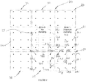
- the digital image is represented or rendered at least in part by a grid of pixels 10 arranged in m columns and n rows where m and n each equal seven.
- the solid circles or dots each represent neighbouring sample points 12 for the pixel grid 10.
- the sample resolution of the digital image is broadly defined by the number of neighbouring sample points 12 within a space occupied by the image or in this case 49 pixels.
- the sample resolution is increased by including intermediate sample points between adjacent of the neighbouring sample points such as 12a to 12d.
- the sample resolution is increased by inserting one additional column and row of sample points between adjacent columns and rows of the grid of pixels 10.
- Each grid position within the additional columns and rows is allocated an intermediate sample point such as 14a.
- Increasing the sample resolution effectively means enlarging the digital image in both its orthogonal x and y axes to expose additional pixels at each of the intermediate sample points such as 14a.
- the resulting enlarged grid at the increased sample resolution will include am columns and bn rows where a and b represents the expansion factors.
- This means the enlarged grid of this example includes 2 x 7 or 14 columns, and 2 x 7 or 14 rows. This equates to an additional 147 intermediate sample points.
- the intermediate sample points such as 14a in the enlarged grid are each populated depending on the influence of a predetermined number of the neighbouring sample points 12.
- the intermediate sample point 14a is deemed to be influenced by all of the neighbouring sample points 12 in the grid 10.
- Each of the predetermined neighbouring points, such as 12e shown in the corner of the grid 10 has a weighted influence on the intermediate sample point 14a substantially proportional to its relative proximity to that point 14a.
- the weighted influence of the neighbouring sample points 12 is determined by one of two techniques, namely (1) combining values at the intermediate sample point, or (2) combining values at each of the predetermined neighbouring sample points.
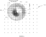
- Figure 3 schematically illustrates the first technique where each of the neighbouring sample points such as 12e is represented by a waveform 16e indicative of that sample point and oriented in a z-axis substantially orthogonal to the grid of pixels 10.
- the indicative waveform 16e is centred at and rotated about the corresponding sample point 12e to intersect with the intermediate sample point 14a.
- the intersection value 17e is thus determined at the intermediate sample point 14.
- These steps are repeated for each of the predetermined neighbouring sample points 12 of the grid 10 to derive weighted values for each of the neighbouring sample points at their intersection with the intermediate sample point 14.
- the intermediate sample point is then populated with the combined weighted values for the indicative waveforms such as 16e of the respective predetermined neighbouring points 12e.
- Figure 3B illustrates the second technique where the intermediate sample points such as 14a are each represented by a hypothetical waveform such as 18e indicative of one of the predetermined neighbouring sample points such as 12e.
- the hypothetical waveform 18e is oriented in a z-axis substantially orthogonal to the grid of pixels 10 in the same manner as the previous technique.
- the hypothetical waveform 18e is centred at and rotated about the intermediate sample point 14a to intersect with the relevant neighbouring sample point such as 12e.
- the intersection of the hypothetical waveform 18e at the neighbouring sample point 12e provides a weighted value 19e for that neighbouring point.
- the indicative or hypothetical waveforms 16 or 18 are in this embodiment constructed at least in part from cosine components represented by absolute results of a cosine function in the spatial domain substantially limited to half a cycle at its mid-point.
- the half-cycle cosine components are summed across the relevant frequency range and this is represented in the computational software program Mathematica as follows: 23. Where x and y are Cartesian coordinates for the intermediate sample point relative to the neighbouring sample point and lpf is equivalent to the Nyquist frequency for the image pixels.
- indicative or hypothetical waveforms are constructed from the following components:
- the waveform components may also be represented by absolute results of a square wave function in the spatial domain substantially limited to half a cycle.
- the half-cycle square-wave components are summed across the relevant frequency range and this is shown in figure 4 and represented in Mathematica as follows:
- the waveform components are each preferably weighted for substantially equal contribution to the indicative or hypothetical waveform. This weighting is shown in the formulae above and may also be approximated as equal areas under each of the waveform component curves.
- Figures 5A and 5B show examples of weighted waveform components for the half cycle cosine function and the square wave function, respectively.
- the indicative or hypothetical waveforms may be constructed by combining waveforms substantially representing x and y coordinates.
- the indicative waveform of the first technique is produced at each of the neighbouring sample points by multiplying the indicative waveform representing the x coordinate with the indicative waveform representing the y coordinate.
- the indicative waveforms of the x and y coordinates are obtained by summing the relevant waveform components for the x and y coordinates respectively.
- To produce the hypothetical waveform of the second technique at the intermediate sample point the hypothetical waveform representing the x coordinate is multiplied with the hypothetical waveform representing the y coordinate.
- the hypothetical waveforms of the x and y coordinates are obtained by summing the relevant waveform components for the x and y coordinates respectively.
- the weightings are then calculated for the first or second techniques by using intersection values for the indicative waveform(s) or the hypothetical waveform at the intermediate sample point or the neighbouring sample points, respectively.
- the filter may be constructed from waveforms or waveform components substantially represented by other mathematical functions.
- the filter may be represented by the equation: n * n/ n ⁇ lpf x * n + lpf x where n is a constant depending on the desired shape, and lpf is equivalent to the Nyquist frequency for the image pixels.
- the variable x is derived from either:
- the image processing comprises a preliminary step of zoning an image such as 20 into resolution zones.
- This is schematically shown in figure 6 where the digital image 20 includes a central zone 22 surrounded by eight neighbouring zones 24 to 38.
- the central zone 22 of the image 20 is relatively detailed requiring high resolution rendering whereas the neighbouring zones such as 24 are of relatively coarse detail of low frequency content requiring relatively low resolution rendering.
- the surrounding low resolution zones 24 to 38 are modified by combining neighbouring sample points such as 24a to 24i.
- the nine neighbouring sample points 24a to 24i are combined with sample points from neighbouring zones to provide a modified zone having substantially the same number of sample points, that is nine (9). This is achieved by combining values for overlapping groups of the neighbouring sample points to derive values in the modified zone.
- the modified value for the central sample point of zone 24 is designated as 24E and so on for other neighbouring sample points within the zone 24.
- the modified value 24E is derived from the combination of values 24a to 24i inclusive and adjusted by a divisor to compensate for the number of samples grouped, in this case nine (9).
- the values for the neighbouring sample points are in this example summed.
- the derivation of values for the modified zones necessarily involves sample points from adjacent zones.
- the modified value 24 ⁇ in the zone 24 is derived from the combination of values 26g and 26h from zone 26; 24a, 24b, 24d, 24e from zone 24; 22i from central zone 22; and 38c 38f from zone 38.
- the modified zones of the image 20 thus have the same number of neighbouring sample points as unmodified zones of the image. This means the grid of the image remains in its original configuration for ease of subsequent image processing such as image filtering.
- the image may also be zoned without requiring the modified zone to account for the same number of sample points as the zone before modification.
- the applicant's co-pending US provisional patent application No. 61/974,326 describes these alternative zoning techniques.
- FIG 7 is a schematic illustration of part of an enlarged grid 30 derived from the image grid 10 having undergone the sample resolution increase with weighting according to the described embodiments of figures 1 to 3 .
- the enlarged grid 30 thus includes the neighbouring 12 together with the weighted intermediate 14 sample points.
- the intermediate sample points 14b to 14e surround the central intermediate sample point 14a.
- the image of the enlarged grid 30 is filtered with a filter 32 representative of the image.
- a preliminary filter is mathematically represented, at the same sample resolution as the enlarged image, by sine functions (sum of cosine components) with weighting according to one of the earlier techniques.
- the filter 32 to be applied to the enlarged image or grid 30 is then constructed by applying the preliminary filter to a hypothetical image represented by binary values (zeros and ones) at the same sample resolution.
- Figure 8 schematically illustrates application of the filter 32 to the enlarged grid 30 stepping the filter 32 across the sample points such as 12a to 12f of the enlarged image.
- the filter 32 is applied to the image as a dot product at high resolution with the benefit of the weighted intermediate sample points as described in the preceding paragraphs.
- the filter 32 is in this example stepped from its intermediate sample point 14a position in figure 7 to its diagonally neighbouring sample point 12b position although this may vary depending on the algorithm adopted in convolving the filter 32 with the image 30.
- the filter 32 in figure 8 is shown at its full resolution with all intersecting grid lines whereas the image is shown at reduced resolution without the intermediate sample points.
- Figure 9 illustrates a variation on this method of convolution where the filter 32 is applied to the image 30. Both the filter 32 and the image 30 may have undergone a sample rate increase according to one of the earlier techniques.
- the image filter 32 is in this variation expanded prior to application to the image of the enlarged grid 30 as follows:
- the filter is applied at its relatively high resolution accounting for the neighbouring and, when a weighted sample rate increase is applied, the intermediate sample points and values.
- the high resolution filter is expanded to effect offset of its sample points relative to corresponding sample points of the image.
- the filter as a result of its expansion is in effect applied to the image at an adjusted sampling rate. This adjusted sampling rate is in this case inversely proportional to the expansion factor
- the sample points of the high resolution filter may be applied to the corresponding sample points of the image as a dot product at an adjusted sampling rate.
- This is schematically depicted in figure 10 where the filter 32 shifts for example to the intermediate sample point 14f. That is the filter 32 moves across its grid at single filter steps corresponding to the sample rate increase of the filter which offsets it from the neighbouring sample points of the image 30.
- the applicant's co-pending International patent application No. PCT/AU2014/000325 describes convolution at an adjusted sampling rate primarily in the context of digital audio signals.
- the filter may be applied to the image without the offset described in the context of figures 9 and 10 . This means the neighbouring sample points of the filter are applied to respective sample points of the image.
- the filter is in this case applied as a dot product at its regular sampling rate without adjustment.
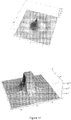
- Figures 11 to 13 are schematic topographic views of exemplary filters applied to the digital image of the previous embodiments.
- the filters are applied to the neighbouring sample points of the enlarged image grid 30.
- the enlarged image grid 30 typically reverts to its original configuration in the form of the image grid 10 by undergoing a sample resolution decrease. This sample resolution decrease is effected by removing the intermediate sample points of the enlarged grid 30.
- the filters constructed in accordance with the previous embodiments are represented by waveforms or waveform components represented by:
- the filter may be represented by waveform components represented by absolute results of a cosine function in the spatial domain substantially limited to half a cycle at its mid-point.
- the waveforms or components thereof may be modified by applying an averaging curve having a width adjusted proportional to the wavelength of the respective waveforms or components. This modification of the waveforms is discussed in the applicant's co-pending International patent application No. PCT/AU2014/000321 .
- Figure 13 illustrates a topographic view of a filter derived from sine functions but without weighting. Although this filter may not be as effective in for example providing clear rendering of a digital image having relative fine detail and requiring high resolution processing, it is nonetheless broadly within the scope and disclosures of the present specification.
- Figure 14 is a topographic view of another filter derived from square-wave components.
- the representative waveform from which the weightings for the filter are derived is shown in Figure 4 .
- the waveforms are calculated for each of the x and y coordinates and multiplied to obtain the indicative or hypothetical waveform. This is effectively the same as the techniques of figures 3A and 3B except the cosine components are replaced with square-wave components, and the waveform components separately represent the waveform in the x and y axes.
- the intention is to minimise distortion artefacts when representing a relatively detailed image at a lower resolution.
- the digital image is enlarged and a filter constructed using one of the techniques of the preferred embodiment.
- the filter is applied to the enlarged image to effect the neighbouring sample points for smoothing of the image.
- the image then undergoes a sample resolution decrease by in effect removing the intermediate sample points.
- the digital image is processed by insertion of additional or intermediate sample points in the form of additional rows and columns of pixels as described earlier.
- the number of rows/columns of inserted pixels is proportional to the scale at which the digital image is to be enlarged.
- the intermediate sample points are then populated according to one of the described techniques of the preferred embodiment.
- the image may also be smoothed by application of a filter derived from the waveforms adopted in populating the intermediate points. In this application the process may not require a subsequent decrease in the sample resolution.
- the digital image is enlarged and intermediate sample points populated according to one of the preferred techniques.
- the relevant neighbouring and/or intermediate sample points are then moved to target locations in the enlarged grid. This movement is typically effected according to a predetermined shifting algorithm which provides the desired translation or rotation.
- the shifted and enlarged image then undergoes a sample resolution decrease to revert to its original size.
- the present invention extends to computer-readable media for carrying or having computer-executable instructions stored thereon.
- the computer-readable media include RAM, ROM, EEPORM, CD-ROM or other optical disc storage, magnetic disc storages, or any other medium which carries or stores program code means in the form of computer-executable instructions.
- the computer In the event of information being transferred or provided over a network or another communications connection to a computer, the computer is to be understood as viewing the connection (hardwired, wireless, or a combination thereof) as a computer-readable medium.
- the invention described herein is susceptible to variations and modifications other than those specifically described.
- the invention may extend to other applications where increasing the sample resolution of the digital image is required in its processing.
- the specific techniques in calculating the influence of neighbouring sample points on intermediate sample points are not intended to be limiting.
- the techniques may involve trigonometric functions other than those described.
- the image filter(s) may be constructed or represented by fast fourier transform (FFT) algorithms rather than the trigonometric functions described in the preferred embodiments, such as the cosine and/or sine components.
- FFT fast fourier transform
- convolution can be applied in the frequency domain instead of the spatial domain. For example filtering in the frequency domain can involve application of FFT algorithms.
Landscapes
- Physics & Mathematics (AREA)
- Engineering & Computer Science (AREA)
- General Physics & Mathematics (AREA)
- Theoretical Computer Science (AREA)
- Geometry (AREA)
- Computer Vision & Pattern Recognition (AREA)
- Image Processing (AREA)
- Editing Of Facsimile Originals (AREA)
Claims (10)
- Verfahren zur Verarbeitung eines digitalen Bilds, wobei das Verfahren die folgenden Schritte umfasst:Erhöhen einer Abtastauflösung des digitalen Bilds, wobei das digitale Bild ein Pixelraster einschließt, das in m Spalten und n Reihen angeordnet ist, und wobei jedes Pixel mit jeweiligen angrenzenden Abtastpunkten assoziiert ist, von einer vorbestimmten Auflösung, die angrenze Abtastpunkte einschließt, zu einer erhöhten Auflösung, die Zwischenabtastpunkte zwischen benachbarten Abtastpunkten der angrenzenden Abtastpunkte einschließt;Ausfüllen von jedem der Zwischenabtastpunkte mit einem Wert, der den Einfluss einer vorbestimmten Anzahl der angrenzenden Abtastpunkte auf den jeweiligen Zwischenabtastpunkt darstellt, wobei der Einfluss der vorbestimmten Anzahl von angrenzenden Punkten proportional zu der Nähe der angrenzenden Abtastpunkte relativ zu dem jeweiligen Zwischenabtastpunkt gewichtet ist,wobei der gewichtete Einfluss bestimmt wird, entweder durch:(A)(i) Darstellen von einem der vorbestimmten angrenzenden Abtastpunkte durch eine eindimensionale Wellenform, die den angrenzenden Abtastpunkt anzeigt und in einer Ebene ausgerichtet ist, die orthogonal zu dem Pixelraster ist;(ii) Zentrieren der anzeigenden Wellenform an dem angrenzenden Abtastpunkt;(iii) Drehen der anzeigenden Wellenform um eine Achse, die innerhalb der Ebene liegt, die orthogonal zu dem Pixelraster ist, und den angrenzenden Abtastpunkt durchquert, sodass die anzeigende Wellenform den Zwischenabtastpunkt schneidet;(iv) Bestimmen eines Schnittpunktwerts der anzeigenden Wellenform an dem Schnittpunkt der anzeigenden Wellenform und des Zwischenabtastpunkts;(v) Ableiten eines gewichteten Werts für den angrenzenden Abtastpunkt von dem Schnittpunktwert;(vi) Wiederholen der Schritte (i)-(v) für jeden der vorbestimmten angrenzenden Abtastpunkte; und(vii) Kombinieren von jedem der abgeleiteten gewichteten Werte, um den Wert zu erhalten, der den Einfluss der vorbestimmten Anzahl von angrenzenden Abtastpunkten auf den jeweiligen Zwischenabtastpunkt darstellt; oder(B)(i) Darstellen von einem der Zwischenabtastpunkte durch eine eindimensionale hypothetische Wellenform, die einen der vorbestimmten angrenzenden Abtastpunkte anzeigt und sich innerhalb einer Ebene, die orthogonal zu dem Pixelraster ist, befindet;(ii) Zentrieren der hypothetischen Wellenform an dem Zwischenabtastpunkt;(iii) Drehen der hypothetischen Wellenform um eine Achse, die innerhalb der Ebene liegt, die orthogonal zu dem Pixelraster ist, und die den Zwischenabtastpunkt durchquert, sodass die hypothetische Wellenform den angrenzenden Abtastpunkt schneidet;(iv) Bestimmen eines Schnittpunktwerts der hypothetischen Wellenform an dem Schnittpunkt der hypothetischen Wellenform und des angrenzenden Abtastpunkts;(v) Ableiten eines gewichteten Werts für den angrenzenden Abtastpunkt von dem Schnittpunktwert;(vi) Wiederholen der Schritte (i)-(v) für jeden der vorbestimmten angrenzenden Abtastpunkte; und(vii) Kombinieren von jedem der abgeleiteten gewichteten Werte, um den Wert zu erhalten, der den Einfluss der vorbestimmten Anzahl von angrenzenden Abtastpunkten auf den jeweiligen Zwischenpunkt darstellt.
- Verfahren nach Anspruch 1, wobei der Schritt des Erhöhens der Abtastauflösung ein Vergrößern des digitalen Bilds auf mindestens einem von einer orthogonalen x- und y-Achse umfasst, um zusätzliche Pixel an jedem der Zwischenabtastpunkte zu exponieren, um ein vergrößertes Raster bereitzustellen, das am Spalten und bn Reihen einschließt, wobei a und b jeweils die Expansionsfaktoren auf der x- und der y-Achse darstellen.
- Verfahren nach Anspruch 2, umfassend den Schritt des Änderns einer Größe oder des Änderns einer Form des digitalen Bilds durch ein Löschen von einem oder mehreren angrenzenden oder Zwischenabtastpunkten des vergrößerten Rasters nach einem vorbestimmten Größenänderungs- oder Formänderungsalgorithmus.
- Verfahren nach Anspruch 3, umfassend ein Verlagern des vergrößerten digitalen Bilds durch ein Verschieben von vorbestimmten Abtastpunkten der angrenzenden Abtastpunkte von existierenden Positionen in dem vergrößerten Raster zu Zielpositionen in dem vergrößerten Raster nach einem vorbestimmten Verlagerungsalgorithmus.
- Verfahren nach einem der vorhergehenden Ansprüche, wobei die anzeigende oder hypothetische Wellenform im räumlichen Bereich durch eine mathematische Funktion dargestellt ist und auf jeder Seite des jeweiligen angrenzenden Abtastpunkts symmetrisch ist.
- Verfahren nach einem der vorhergehenden Ansprüche, wobei die anzeigende oder hypothetische Wellenform oder Komponenten der anzeigenden oder hypothetischen Wellenform durch absolute Ergebnisse einer Kosinusfunktion in dem räumlichen Bereich, der auf einen halben Zyklus begrenzt ist, in dessen Mittelpunkt dargestellt sind.
- Verfahren nach einem der Ansprüche 1-5, wobei die anzeigende oder hypothetische Wellenform oder Komponenten der anzeigenden oder hypothetischen Wellenform durch eine Sinusfunktion von positiven Werten nur in dem räumlichen Bereich dargestellt sind.
- Verfahren nach einem der vorhergehenden Ansprüche, das die folgenden Schritte umfasst:Bereitstellen eines digitalen Filters, der eine Abtastauflösung aufweist, die dieselbe ist wie die vorbestimmte Auflösung des digitalen Bilds, wobei der Filter eine Mittelpunktabtastung und eine Vielzahl von angrenzenden Abtastpunkten auf jeder Seite der Mittelpunktabtastung einschließt; undAnwenden des digitalen Filters auf das digitale Bild, wobei:(i) die Mittelpunktabtastung des Filters auf einen entsprechenden Abtastpunkt des Bilds angewendet wird;(ii) die angrenzenden Abtastpunkte des Filters auf die jeweiligen der Zwischenabtastpunkte oder den angrenzenden Abtastpunkt des Signals angewendet werden.
- Computer- oder vorrichtungslesbares Medium, das Anweisungen zur Verarbeitung eines digitalen Bilds einschließt, wobei das digitale Bild ein Pixelraster einschließt, das in m Spalten und n Reihen angeordnet ist, und wobei jedes Pixel mit jeweiligen angrenzenden Abtastpunkten assoziiert ist, wobei die Anweisungen, wenn sie durch einen Prozessor ausgeführt werden, den Prozessor zu Folgendem veranlassen:Erhöhen der Abtastauflösung des digitalen Bilds von einer vorbestimmten Auflösung, die angrenzende Abtastpunkte einschließt, zu einer erhöhten Auflösung, die Zwischenabtastpunkte zwischen benachbarten der angrenzenden Abtastpunkte einschließt; undAusfüllen von jedem der Zwischenabtastpunkte mit einem Wert, der den Einfluss einer vorbestimmten Anzahl der angrenzenden Abtastpunkte auf den jeweiligen Zwischenabtastpunkt darstellt, wobei der Einfluss proportional zu der Nähe der angrenzenden Abtastpunkte relativ zu den jeweiligen Zwischenpunkten gewichtet ist, wobei die Anweisungen ferner Anweisungen umfassen, die, wenn sie durch den Prozessor ausgeführt werden, den Prozessor dazu veranlassen, entweder(A)(i) einen der vorbestimmten angrenzenden Abtastpunkte durch eine eindimensionale Wellenform darzustellen, die den angrenzenden Abtastpunkt anzeigt und in einer Ebene ausgerichtet ist, die orthogonal zu dem Pixelraster ist;(ii) die anzeigende Wellenform an dem angrenzenden Abtastpunkt zu zentrieren;(iii) die anzeigende Wellenform um eine Achse, die innerhalb der Ebene liegt, die orthogonal zu dem Pixelraster ist, und den angrenzenden Abtastpunkt durchquert, zu drehen, sodass die anzeigende Wellenform den Zwischenabtastpunkt schneidet;(iv) einen Schnittpunktwert der anzeigenden Wellenform an dem Schnittpunkt der anzeigenden Wellenform und des Zwischenabtastpunkts zu bestimmen;(v) einen gewichteten Wert für den angrenzenden Abtastpunkt von dem Schnittpunktwert abzuleiten;(vi) die Schritte (i)-(v) für jeden der vorbestimmten angrenzenden Abtastpunkte zu wiederholen; und(vii) jeden der abgeleiteten gewichteten Werte zu kombinieren, um den Wert zu erhalten, der den Einfluss der vorbestimmten Anzahl von angrenzenden Abtastpunkten auf den jeweiligen Zwischenpunkt darstellt; oder(B)(i) einen der Zwischenabtastpunkte durch eine eindimensionale hypothetische Wellenform darzustellen, die einen der vorbestimmten angrenzenden Abtastpunkte anzeigt und sich innerhalb einer Ebene befindet, die orthogonal zu dem Pixelraster ist;(ii) die hypothetische Wellenform an dem Zwischenabtastpunkt zu zentrieren;(iii) die hypothetische Wellenform um eine Achse zu drehen, die innerhalb der Ebene liegt, die orthogonal zu dem Pixelraster ist, und den Zwischenabtastpunkt durchquert, sodass die hypothetische Wellenform den angrenzenden Abtastpunkt schneidet;(iv) einen Schnittpunktwert der hypothetischen Wellenform an dem Schnittpunkt der hypothetischen Wellenform und des angrenzenden Abtastpunkts zu bestimmen;(v) einen gewichteten Wert für den angrenzenden Abtastpunkt von dem Schnittpunktwert abzuleiten;(vi) die Schritte (i)-(v) für jeden der vorbestimmten angrenzenden Abtastpunkte zu wiederholen; und(vii) jeden der abgeleiteten gewichteten Werte zu kombinieren, um den Wert zu erhalten, der den Einfluss der vorbestimmten Anzahl an angrenzenden Abtastpunkten auf den jeweiligen Zwischenpunkt darstellt.
- Computersystem zur Verarbeitung eines digitalen Bilds, wobei das System einen Prozessor umfasst, der zu Folgendem konfiguriert ist:Erhöhen einer Abtastauflösung des digitalen Bilds, wobei das digitale Bild ein Pixelraster einschließt, dass in m Spalten und n Reihen angeordnet ist, und wobei jedes Pixel mit jeweiligen angrenzenden Abtastpunkten assoziiert ist, von einer vorbestimmten Auflösung, die angrenzende Abtastpunkte einschließt, zu einer erhöhten Auflösung, die Zwischenabtastpunkte zwischen benachbarten der angrenzenden Abtastpunkte einschließt; undAusfüllen von jedem der Zwischenabtastpunkte mit einem Wert, der den Einfluss einer vorbestimmen Anzahl der angrenzenden Abtastpunkte auf den jeweiligen Zwischenabtastpunkt darstellt, wobei der Einfluss proportional zu der Nähe der angrenzenden Abtastpunkte relativ zu den jeweiligen Zwischenabtastpunkten gewichtet ist; wobei der Prozessor ferner dazu konfiguriert ist:(A)(i) einen der vorbestimmten angrenzenden Abtastpunkte durch eine eindimensionale Wellenform darzustellen, die den angrenzenden Abtastpunkt anzeigt und in einer Ebene ausgerichtet ist, die orthogonal zu dem Pixelraster ist;(ii) die anzeigende Wellenform an dem angrenzenden Abtastpunkt zu zentrieren;(iii)die anzeigende Wellenform um eine Achse zu drehen, die in der Ebene liegt, die orthogonal zu dem Pixelraster ist, und den angrenzenden Abtastpunkt durchquert, sodass die anzeigende Wellenform den Zwischenabtastpunkt schneidet;(iv) einen Schnittpunktwert der anzeigenden Wellenform an dem Schnittpunkt der anzeigenden Wellenform und des Zwischenabtastpunkts zu bestimmen;(v) einen gewichteten Wert für den angrenzenden Abtastpunkt von dem Schnittpunktwert abzuleiten;(vi) die Schritte (i)-(v) für jeden der vorbestimmten angrenzenden Abtastpunkte zu wiederholen; und(vii) jeden der abgeleiteten gewichteten Werte zu kombinieren, um den Wert zu erhalten, der den Einfluss der vorbestimmten Anzahl von angrenzenden Abtastpunkten auf den jeweiligen Zwischenpunkt darstellt; oder(B)(i) einen der Zwischenabtastpunkte durch eine eindimensionale hypothetische Wellenform darzustellen, die einen der vorbestimmten angrenzenden Abtastpunkte anzeigt und sich innerhalb einer Ebene befindet, die orthogonal zu dem Pixelraster ist;(ii) die hypothetische Wellenform an dem Zwischenabtastpunkt zu zentrieren;(iii) die hypothetische Wellenform um eine Achse zu drehen, die innerhalb der Ebene liegt, die orthogonal zu dem Pixelraster ist, und den Zwischenabtastpunkt durchquert, sodass die hypothetische Wellenform den angrenzenden Abtastpunkt schneidet;(iv) einen Schnittpunktwert der hypothetischen Wellenform an dem Schnittpunkt der hypothetischen Wellenform und des angrenzenden Abtastpunkts zu bestimmen;(v) einen gewichteten Wert für den angrenzenden Abtastpunkt von dem Schnittpunktwert abzuleiten;(vi) die Schritte (i)-(v) für jeden der vorbestimmten angrenzenden Abtastpunkte zu wiederholen; und(vii) jeden der abgeleiteten gewichteten Werte zu kombinieren, um den Wert zu erhalten, der den Einfluss der vorbestimmten Anzahl von angrenzenden Abtastpunkten auf den jeweiligen Zwischenpunkt darstellt.
Applications Claiming Priority (3)
| Application Number | Priority Date | Filing Date | Title |
|---|---|---|---|
| US201462056345P | 2014-09-26 | 2014-09-26 | |
| US201462091327P | 2014-12-12 | 2014-12-12 | |
| PCT/AU2015/050577 WO2016044897A1 (en) | 2014-09-26 | 2015-09-26 | Image processing |
Publications (3)
| Publication Number | Publication Date |
|---|---|
| EP3198554A1 EP3198554A1 (de) | 2017-08-02 |
| EP3198554A4 EP3198554A4 (de) | 2018-03-07 |
| EP3198554B1 true EP3198554B1 (de) | 2019-04-24 |
Family
ID=55579968
Family Applications (1)
| Application Number | Title | Priority Date | Filing Date |
|---|---|---|---|
| EP15844017.2A Not-in-force EP3198554B1 (de) | 2014-09-26 | 2015-09-26 | Bildverarbeitung |
Country Status (4)
| Country | Link |
|---|---|
| US (1) | US10417740B2 (de) |
| EP (1) | EP3198554B1 (de) |
| KR (1) | KR20170072227A (de) |
| WO (1) | WO2016044897A1 (de) |
Families Citing this family (1)
| Publication number | Priority date | Publication date | Assignee | Title |
|---|---|---|---|---|
| US20220101494A1 (en) * | 2020-09-30 | 2022-03-31 | Nvidia Corporation | Fourier transform-based image synthesis using neural networks |
Family Cites Families (9)
| Publication number | Priority date | Publication date | Assignee | Title |
|---|---|---|---|---|
| US6763148B1 (en) * | 2000-11-13 | 2004-07-13 | Visual Key, Inc. | Image recognition methods |
| US6816622B2 (en) * | 2001-10-18 | 2004-11-09 | Microsoft Corporation | Generating resized images using ripple free image filtering |
| JP4392584B2 (ja) * | 2003-06-27 | 2010-01-06 | ソニー株式会社 | 信号処理装置および信号処理方法、並びにプログラムおよび記録媒体 |
| US7437018B1 (en) * | 2003-09-26 | 2008-10-14 | Adobe Systems Incorporated | Image resampling using variable quantization bins |
| US7817871B2 (en) * | 2004-08-18 | 2010-10-19 | Adobe Systems Incorporated | Scaling of raster images without blurring of edges |
| US7777812B2 (en) * | 2005-11-18 | 2010-08-17 | Sharp Laboratories Of America, Inc. | Methods and systems for picture resampling |
| AU2007249113B2 (en) * | 2007-12-19 | 2011-11-03 | Canon Kabushiki Kaisha | Orientation adapted aliasing cancellation |
| JP4508279B2 (ja) * | 2008-07-17 | 2010-07-21 | ソニー株式会社 | 画像処理装置、画像処理方法、及び、プログラム |
| US20110298972A1 (en) * | 2010-06-04 | 2011-12-08 | Stmicroelectronics Asia Pacific Pte. Ltd. | System and process for image rescaling using adaptive interpolation kernel with sharpness and de-ringing control |
-
2015
- 2015-09-26 EP EP15844017.2A patent/EP3198554B1/de not_active Not-in-force
- 2015-09-26 WO PCT/AU2015/050577 patent/WO2016044897A1/en not_active Ceased
- 2015-09-26 US US15/514,478 patent/US10417740B2/en not_active Expired - Fee Related
- 2015-09-26 KR KR1020177011363A patent/KR20170072227A/ko not_active Withdrawn
Non-Patent Citations (1)
| Title |
|---|
| None * |
Also Published As
| Publication number | Publication date |
|---|---|
| US10417740B2 (en) | 2019-09-17 |
| WO2016044897A9 (en) | 2016-05-26 |
| WO2016044897A1 (en) | 2016-03-31 |
| EP3198554A4 (de) | 2018-03-07 |
| EP3198554A1 (de) | 2017-08-02 |
| US20170249720A1 (en) | 2017-08-31 |
| KR20170072227A (ko) | 2017-06-26 |
Similar Documents
| Publication | Publication Date | Title |
|---|---|---|
| US8666154B2 (en) | Interpolation | |
| US8588554B2 (en) | Interpolation | |
| WO2015080986A1 (en) | Content-aware image rotation | |
| Occorsio et al. | Image scaling by de la Vallée-Poussin filtered interpolation | |
| Rahim et al. | An analysis of interpolation methods for super resolution images | |
| JP2008512766A (ja) | 異方性フィルタリングを用いたシングルパス画像ワーピングシステム及び方法 | |
| US7437018B1 (en) | Image resampling using variable quantization bins | |
| Suresh et al. | A comparative analysis of image scaling algorithms | |
| US10417740B2 (en) | Image processing | |
| CN110490795B (zh) | 利用经由蓝噪声采样选择的像素集来缩小图像 | |
| JP6542524B2 (ja) | 画像処理装置、画像処理方法、およびプログラム | |
| Zhao et al. | Real-time edge-aware weighted median filtering on the GPU | |
| Fan et al. | Preservation of image edge feature based on snowfall model smoothing filter | |
| WO2018099303A1 (zh) | 一种图像去噪的方法、装置及计算机存储介质 | |
| JP5559222B2 (ja) | 異方性フィルタリングを用いたシングルパス画像ワーピングシステム及び方法 | |
| Pan et al. | Fractional directional derivative and identification of blur parameters of motion-blurred image | |
| CN118037553A (zh) | 基于2d-vmd和插值的图像增强方法 | |
| CN107220952A (zh) | 一种基于显著性的多尺度图像平滑方法 | |
| JP7178818B2 (ja) | 画像処理装置 | |
| Penalver et al. | Interferogram smoothing and skelotonizing using Bessel functions of the first kind | |
| JP2016076168A (ja) | 超解像装置及びプログラム | |
| Zhang | Frequency domain filtering | |
| Cuevas et al. | Spatial Filters | |
| WO2013078451A1 (en) | Methods of determining local spectrum at a pixel using a rotationally invariant s-transform (rist) | |
| Easley et al. | Hyperbolic shearlets |
Legal Events
| Date | Code | Title | Description |
|---|---|---|---|
| STAA | Information on the status of an ep patent application or granted ep patent |
Free format text: STATUS: THE INTERNATIONAL PUBLICATION HAS BEEN MADE |
|
| PUAI | Public reference made under article 153(3) epc to a published international application that has entered the european phase |
Free format text: ORIGINAL CODE: 0009012 |
|
| STAA | Information on the status of an ep patent application or granted ep patent |
Free format text: STATUS: REQUEST FOR EXAMINATION WAS MADE |
|
| 17P | Request for examination filed |
Effective date: 20170421 |
|
| AK | Designated contracting states |
Kind code of ref document: A1 Designated state(s): AL AT BE BG CH CY CZ DE DK EE ES FI FR GB GR HR HU IE IS IT LI LT LU LV MC MK MT NL NO PL PT RO RS SE SI SK SM TR |
|
| AX | Request for extension of the european patent |
Extension state: BA ME |
|
| DAV | Request for validation of the european patent (deleted) | ||
| DAX | Request for extension of the european patent (deleted) | ||
| A4 | Supplementary search report drawn up and despatched |
Effective date: 20180205 |
|
| RIC1 | Information provided on ipc code assigned before grant |
Ipc: G06T 3/60 20060101ALI20180130BHEP Ipc: G06T 3/40 20060101AFI20180130BHEP Ipc: G06T 7/60 20170101ALI20180130BHEP Ipc: G06T 5/10 20060101ALI20180130BHEP |
|
| GRAP | Despatch of communication of intention to grant a patent |
Free format text: ORIGINAL CODE: EPIDOSNIGR1 |
|
| STAA | Information on the status of an ep patent application or granted ep patent |
Free format text: STATUS: GRANT OF PATENT IS INTENDED |
|
| INTG | Intention to grant announced |
Effective date: 20181119 |
|
| GRAS | Grant fee paid |
Free format text: ORIGINAL CODE: EPIDOSNIGR3 |
|
| GRAA | (expected) grant |
Free format text: ORIGINAL CODE: 0009210 |
|
| STAA | Information on the status of an ep patent application or granted ep patent |
Free format text: STATUS: THE PATENT HAS BEEN GRANTED |
|
| AK | Designated contracting states |
Kind code of ref document: B1 Designated state(s): AL AT BE BG CH CY CZ DE DK EE ES FI FR GB GR HR HU IE IS IT LI LT LU LV MC MK MT NL NO PL PT RO RS SE SI SK SM TR |
|
| REG | Reference to a national code |
Ref country code: GB Ref legal event code: FG4D |
|
| REG | Reference to a national code |
Ref country code: CH Ref legal event code: EP |
|
| REG | Reference to a national code |
Ref country code: AT Ref legal event code: REF Ref document number: 1125018 Country of ref document: AT Kind code of ref document: T Effective date: 20190515 Ref country code: IE Ref legal event code: FG4D |
|
| REG | Reference to a national code |
Ref country code: DE Ref legal event code: R096 Ref document number: 602015029080 Country of ref document: DE |
|
| REG | Reference to a national code |
Ref country code: NL Ref legal event code: MP Effective date: 20190424 |
|
| REG | Reference to a national code |
Ref country code: LT Ref legal event code: MG4D |
|
| PG25 | Lapsed in a contracting state [announced via postgrant information from national office to epo] |
Ref country code: NL Free format text: LAPSE BECAUSE OF FAILURE TO SUBMIT A TRANSLATION OF THE DESCRIPTION OR TO PAY THE FEE WITHIN THE PRESCRIBED TIME-LIMIT Effective date: 20190424 |
|
| PG25 | Lapsed in a contracting state [announced via postgrant information from national office to epo] |
Ref country code: AL Free format text: LAPSE BECAUSE OF FAILURE TO SUBMIT A TRANSLATION OF THE DESCRIPTION OR TO PAY THE FEE WITHIN THE PRESCRIBED TIME-LIMIT Effective date: 20190424 Ref country code: PT Free format text: LAPSE BECAUSE OF FAILURE TO SUBMIT A TRANSLATION OF THE DESCRIPTION OR TO PAY THE FEE WITHIN THE PRESCRIBED TIME-LIMIT Effective date: 20190824 Ref country code: SE Free format text: LAPSE BECAUSE OF FAILURE TO SUBMIT A TRANSLATION OF THE DESCRIPTION OR TO PAY THE FEE WITHIN THE PRESCRIBED TIME-LIMIT Effective date: 20190424 Ref country code: FI Free format text: LAPSE BECAUSE OF FAILURE TO SUBMIT A TRANSLATION OF THE DESCRIPTION OR TO PAY THE FEE WITHIN THE PRESCRIBED TIME-LIMIT Effective date: 20190424 Ref country code: NO Free format text: LAPSE BECAUSE OF FAILURE TO SUBMIT A TRANSLATION OF THE DESCRIPTION OR TO PAY THE FEE WITHIN THE PRESCRIBED TIME-LIMIT Effective date: 20190724 Ref country code: HR Free format text: LAPSE BECAUSE OF FAILURE TO SUBMIT A TRANSLATION OF THE DESCRIPTION OR TO PAY THE FEE WITHIN THE PRESCRIBED TIME-LIMIT Effective date: 20190424 Ref country code: LT Free format text: LAPSE BECAUSE OF FAILURE TO SUBMIT A TRANSLATION OF THE DESCRIPTION OR TO PAY THE FEE WITHIN THE PRESCRIBED TIME-LIMIT Effective date: 20190424 |
|
| PG25 | Lapsed in a contracting state [announced via postgrant information from national office to epo] |
Ref country code: RS Free format text: LAPSE BECAUSE OF FAILURE TO SUBMIT A TRANSLATION OF THE DESCRIPTION OR TO PAY THE FEE WITHIN THE PRESCRIBED TIME-LIMIT Effective date: 20190424 Ref country code: PL Free format text: LAPSE BECAUSE OF FAILURE TO SUBMIT A TRANSLATION OF THE DESCRIPTION OR TO PAY THE FEE WITHIN THE PRESCRIBED TIME-LIMIT Effective date: 20190424 Ref country code: BG Free format text: LAPSE BECAUSE OF FAILURE TO SUBMIT A TRANSLATION OF THE DESCRIPTION OR TO PAY THE FEE WITHIN THE PRESCRIBED TIME-LIMIT Effective date: 20190724 Ref country code: LV Free format text: LAPSE BECAUSE OF FAILURE TO SUBMIT A TRANSLATION OF THE DESCRIPTION OR TO PAY THE FEE WITHIN THE PRESCRIBED TIME-LIMIT Effective date: 20190424 Ref country code: GR Free format text: LAPSE BECAUSE OF FAILURE TO SUBMIT A TRANSLATION OF THE DESCRIPTION OR TO PAY THE FEE WITHIN THE PRESCRIBED TIME-LIMIT Effective date: 20190725 |
|
| REG | Reference to a national code |
Ref country code: AT Ref legal event code: MK05 Ref document number: 1125018 Country of ref document: AT Kind code of ref document: T Effective date: 20190424 |
|
| PG25 | Lapsed in a contracting state [announced via postgrant information from national office to epo] |
Ref country code: IS Free format text: LAPSE BECAUSE OF FAILURE TO SUBMIT A TRANSLATION OF THE DESCRIPTION OR TO PAY THE FEE WITHIN THE PRESCRIBED TIME-LIMIT Effective date: 20190824 |
|
| REG | Reference to a national code |
Ref country code: DE Ref legal event code: R097 Ref document number: 602015029080 Country of ref document: DE |
|
| PG25 | Lapsed in a contracting state [announced via postgrant information from national office to epo] |
Ref country code: EE Free format text: LAPSE BECAUSE OF FAILURE TO SUBMIT A TRANSLATION OF THE DESCRIPTION OR TO PAY THE FEE WITHIN THE PRESCRIBED TIME-LIMIT Effective date: 20190424 Ref country code: DK Free format text: LAPSE BECAUSE OF FAILURE TO SUBMIT A TRANSLATION OF THE DESCRIPTION OR TO PAY THE FEE WITHIN THE PRESCRIBED TIME-LIMIT Effective date: 20190424 Ref country code: AT Free format text: LAPSE BECAUSE OF FAILURE TO SUBMIT A TRANSLATION OF THE DESCRIPTION OR TO PAY THE FEE WITHIN THE PRESCRIBED TIME-LIMIT Effective date: 20190424 Ref country code: SK Free format text: LAPSE BECAUSE OF FAILURE TO SUBMIT A TRANSLATION OF THE DESCRIPTION OR TO PAY THE FEE WITHIN THE PRESCRIBED TIME-LIMIT Effective date: 20190424 Ref country code: CZ Free format text: LAPSE BECAUSE OF FAILURE TO SUBMIT A TRANSLATION OF THE DESCRIPTION OR TO PAY THE FEE WITHIN THE PRESCRIBED TIME-LIMIT Effective date: 20190424 Ref country code: RO Free format text: LAPSE BECAUSE OF FAILURE TO SUBMIT A TRANSLATION OF THE DESCRIPTION OR TO PAY THE FEE WITHIN THE PRESCRIBED TIME-LIMIT Effective date: 20190424 |
|
| PG25 | Lapsed in a contracting state [announced via postgrant information from national office to epo] |
Ref country code: SM Free format text: LAPSE BECAUSE OF FAILURE TO SUBMIT A TRANSLATION OF THE DESCRIPTION OR TO PAY THE FEE WITHIN THE PRESCRIBED TIME-LIMIT Effective date: 20190424 Ref country code: IT Free format text: LAPSE BECAUSE OF FAILURE TO SUBMIT A TRANSLATION OF THE DESCRIPTION OR TO PAY THE FEE WITHIN THE PRESCRIBED TIME-LIMIT Effective date: 20190424 |
|
| PLBE | No opposition filed within time limit |
Free format text: ORIGINAL CODE: 0009261 |
|
| STAA | Information on the status of an ep patent application or granted ep patent |
Free format text: STATUS: NO OPPOSITION FILED WITHIN TIME LIMIT |
|
| PG25 | Lapsed in a contracting state [announced via postgrant information from national office to epo] |
Ref country code: TR Free format text: LAPSE BECAUSE OF FAILURE TO SUBMIT A TRANSLATION OF THE DESCRIPTION OR TO PAY THE FEE WITHIN THE PRESCRIBED TIME-LIMIT Effective date: 20190424 |
|
| 26N | No opposition filed |
Effective date: 20200127 |
|
| PG25 | Lapsed in a contracting state [announced via postgrant information from national office to epo] |
Ref country code: MC Free format text: LAPSE BECAUSE OF FAILURE TO SUBMIT A TRANSLATION OF THE DESCRIPTION OR TO PAY THE FEE WITHIN THE PRESCRIBED TIME-LIMIT Effective date: 20190424 Ref country code: SI Free format text: LAPSE BECAUSE OF FAILURE TO SUBMIT A TRANSLATION OF THE DESCRIPTION OR TO PAY THE FEE WITHIN THE PRESCRIBED TIME-LIMIT Effective date: 20190424 |
|
| REG | Reference to a national code |
Ref country code: CH Ref legal event code: PL |
|
| PG25 | Lapsed in a contracting state [announced via postgrant information from national office to epo] |
Ref country code: LU Free format text: LAPSE BECAUSE OF NON-PAYMENT OF DUE FEES Effective date: 20190926 Ref country code: CH Free format text: LAPSE BECAUSE OF NON-PAYMENT OF DUE FEES Effective date: 20190930 Ref country code: LI Free format text: LAPSE BECAUSE OF NON-PAYMENT OF DUE FEES Effective date: 20190930 |
|
| REG | Reference to a national code |
Ref country code: BE Ref legal event code: MM Effective date: 20190930 |
|
| PG25 | Lapsed in a contracting state [announced via postgrant information from national office to epo] |
Ref country code: BE Free format text: LAPSE BECAUSE OF NON-PAYMENT OF DUE FEES Effective date: 20190930 |
|
| PG25 | Lapsed in a contracting state [announced via postgrant information from national office to epo] |
Ref country code: ES Free format text: LAPSE BECAUSE OF FAILURE TO SUBMIT A TRANSLATION OF THE DESCRIPTION OR TO PAY THE FEE WITHIN THE PRESCRIBED TIME-LIMIT Effective date: 20190424 |
|
| PGFP | Annual fee paid to national office [announced via postgrant information from national office to epo] |
Ref country code: FR Payment date: 20200924 Year of fee payment: 6 Ref country code: DE Payment date: 20200930 Year of fee payment: 6 Ref country code: IE Payment date: 20200929 Year of fee payment: 6 Ref country code: GB Payment date: 20200928 Year of fee payment: 6 |
|
| PG25 | Lapsed in a contracting state [announced via postgrant information from national office to epo] |
Ref country code: CY Free format text: LAPSE BECAUSE OF FAILURE TO SUBMIT A TRANSLATION OF THE DESCRIPTION OR TO PAY THE FEE WITHIN THE PRESCRIBED TIME-LIMIT Effective date: 20190424 |
|
| PG25 | Lapsed in a contracting state [announced via postgrant information from national office to epo] |
Ref country code: HU Free format text: LAPSE BECAUSE OF FAILURE TO SUBMIT A TRANSLATION OF THE DESCRIPTION OR TO PAY THE FEE WITHIN THE PRESCRIBED TIME-LIMIT; INVALID AB INITIO Effective date: 20150926 Ref country code: MT Free format text: LAPSE BECAUSE OF FAILURE TO SUBMIT A TRANSLATION OF THE DESCRIPTION OR TO PAY THE FEE WITHIN THE PRESCRIBED TIME-LIMIT Effective date: 20190424 |
|
| REG | Reference to a national code |
Ref country code: DE Ref legal event code: R119 Ref document number: 602015029080 Country of ref document: DE |
|
| GBPC | Gb: european patent ceased through non-payment of renewal fee |
Effective date: 20210926 |
|
| PG25 | Lapsed in a contracting state [announced via postgrant information from national office to epo] |
Ref country code: MK Free format text: LAPSE BECAUSE OF FAILURE TO SUBMIT A TRANSLATION OF THE DESCRIPTION OR TO PAY THE FEE WITHIN THE PRESCRIBED TIME-LIMIT Effective date: 20190424 |
|
| PG25 | Lapsed in a contracting state [announced via postgrant information from national office to epo] |
Ref country code: IE Free format text: LAPSE BECAUSE OF NON-PAYMENT OF DUE FEES Effective date: 20210926 Ref country code: GB Free format text: LAPSE BECAUSE OF NON-PAYMENT OF DUE FEES Effective date: 20210926 Ref country code: FR Free format text: LAPSE BECAUSE OF NON-PAYMENT OF DUE FEES Effective date: 20210930 Ref country code: DE Free format text: LAPSE BECAUSE OF NON-PAYMENT OF DUE FEES Effective date: 20220401 |