EP3198281B1 - Ellagsäureformulierungen zur verwendung bei gerinnungstests - Google Patents
Ellagsäureformulierungen zur verwendung bei gerinnungstests Download PDFInfo
- Publication number
- EP3198281B1 EP3198281B1 EP15782124.0A EP15782124A EP3198281B1 EP 3198281 B1 EP3198281 B1 EP 3198281B1 EP 15782124 A EP15782124 A EP 15782124A EP 3198281 B1 EP3198281 B1 EP 3198281B1
- Authority
- EP
- European Patent Office
- Prior art keywords
- cyclodextrin
- ellagic acid
- sensor
- conduit
- sample
- Prior art date
- Legal status (The legal status is an assumption and is not a legal conclusion. Google has not performed a legal analysis and makes no representation as to the accuracy of the status listed.)
- Active
Links
Images


Classifications
-
- G—PHYSICS
- G01—MEASURING; TESTING
- G01N—INVESTIGATING OR ANALYSING MATERIALS BY DETERMINING THEIR CHEMICAL OR PHYSICAL PROPERTIES
- G01N33/00—Investigating or analysing materials by specific methods not covered by groups G01N1/00 - G01N31/00
- G01N33/48—Biological material, e.g. blood, urine; Haemocytometers
- G01N33/50—Chemical analysis of biological material, e.g. blood, urine; Testing involving biospecific ligand binding methods; Immunological testing
- G01N33/86—Chemical analysis of biological material, e.g. blood, urine; Testing involving biospecific ligand binding methods; Immunological testing involving blood coagulating time or factors, or their receptors
-
- B—PERFORMING OPERATIONS; TRANSPORTING
- B01—PHYSICAL OR CHEMICAL PROCESSES OR APPARATUS IN GENERAL
- B01L—CHEMICAL OR PHYSICAL LABORATORY APPARATUS FOR GENERAL USE
- B01L3/00—Containers or dishes for laboratory use, e.g. laboratory glassware; Droppers
- B01L3/50—Containers for the purpose of retaining a material to be analysed, e.g. test tubes
- B01L3/502—Containers for the purpose of retaining a material to be analysed, e.g. test tubes with fluid transport, e.g. in multi-compartment structures
- B01L3/5027—Containers for the purpose of retaining a material to be analysed, e.g. test tubes with fluid transport, e.g. in multi-compartment structures by integrated microfluidic structures, i.e. dimensions of channels and chambers are such that surface tension forces are important, e.g. lab-on-a-chip
-
- B—PERFORMING OPERATIONS; TRANSPORTING
- B01—PHYSICAL OR CHEMICAL PROCESSES OR APPARATUS IN GENERAL
- B01L—CHEMICAL OR PHYSICAL LABORATORY APPARATUS FOR GENERAL USE
- B01L2200/00—Solutions for specific problems relating to chemical or physical laboratory apparatus
- B01L2200/06—Fluid handling related problems
- B01L2200/0605—Metering of fluids
-
- B—PERFORMING OPERATIONS; TRANSPORTING
- B01—PHYSICAL OR CHEMICAL PROCESSES OR APPARATUS IN GENERAL
- B01L—CHEMICAL OR PHYSICAL LABORATORY APPARATUS FOR GENERAL USE
- B01L2200/00—Solutions for specific problems relating to chemical or physical laboratory apparatus
- B01L2200/06—Fluid handling related problems
- B01L2200/0684—Venting, avoiding backpressure, avoid gas bubbles
-
- B—PERFORMING OPERATIONS; TRANSPORTING
- B01—PHYSICAL OR CHEMICAL PROCESSES OR APPARATUS IN GENERAL
- B01L—CHEMICAL OR PHYSICAL LABORATORY APPARATUS FOR GENERAL USE
- B01L2200/00—Solutions for specific problems relating to chemical or physical laboratory apparatus
- B01L2200/06—Fluid handling related problems
- B01L2200/0689—Sealing
-
- B—PERFORMING OPERATIONS; TRANSPORTING
- B01—PHYSICAL OR CHEMICAL PROCESSES OR APPARATUS IN GENERAL
- B01L—CHEMICAL OR PHYSICAL LABORATORY APPARATUS FOR GENERAL USE
- B01L2200/00—Solutions for specific problems relating to chemical or physical laboratory apparatus
- B01L2200/16—Reagents, handling or storing thereof
-
- B—PERFORMING OPERATIONS; TRANSPORTING
- B01—PHYSICAL OR CHEMICAL PROCESSES OR APPARATUS IN GENERAL
- B01L—CHEMICAL OR PHYSICAL LABORATORY APPARATUS FOR GENERAL USE
- B01L2300/00—Additional constructional details
- B01L2300/02—Identification, exchange or storage of information
- B01L2300/024—Storing results with means integrated into the container
-
- B—PERFORMING OPERATIONS; TRANSPORTING
- B01—PHYSICAL OR CHEMICAL PROCESSES OR APPARATUS IN GENERAL
- B01L—CHEMICAL OR PHYSICAL LABORATORY APPARATUS FOR GENERAL USE
- B01L2300/00—Additional constructional details
- B01L2300/02—Identification, exchange or storage of information
- B01L2300/025—Displaying results or values with integrated means
- B01L2300/027—Digital display, e.g. LCD, LED
-
- B—PERFORMING OPERATIONS; TRANSPORTING
- B01—PHYSICAL OR CHEMICAL PROCESSES OR APPARATUS IN GENERAL
- B01L—CHEMICAL OR PHYSICAL LABORATORY APPARATUS FOR GENERAL USE
- B01L2300/00—Additional constructional details
- B01L2300/06—Auxiliary integrated devices, integrated components
- B01L2300/0627—Sensor or part of a sensor is integrated
- B01L2300/0636—Integrated biosensor, microarrays
-
- B—PERFORMING OPERATIONS; TRANSPORTING
- B01—PHYSICAL OR CHEMICAL PROCESSES OR APPARATUS IN GENERAL
- B01L—CHEMICAL OR PHYSICAL LABORATORY APPARATUS FOR GENERAL USE
- B01L2300/00—Additional constructional details
- B01L2300/06—Auxiliary integrated devices, integrated components
- B01L2300/0627—Sensor or part of a sensor is integrated
- B01L2300/0645—Electrodes
-
- B—PERFORMING OPERATIONS; TRANSPORTING
- B01—PHYSICAL OR CHEMICAL PROCESSES OR APPARATUS IN GENERAL
- B01L—CHEMICAL OR PHYSICAL LABORATORY APPARATUS FOR GENERAL USE
- B01L2300/00—Additional constructional details
- B01L2300/06—Auxiliary integrated devices, integrated components
- B01L2300/069—Absorbents; Gels to retain a fluid
-
- B—PERFORMING OPERATIONS; TRANSPORTING
- B01—PHYSICAL OR CHEMICAL PROCESSES OR APPARATUS IN GENERAL
- B01L—CHEMICAL OR PHYSICAL LABORATORY APPARATUS FOR GENERAL USE
- B01L2300/00—Additional constructional details
- B01L2300/08—Geometry, shape and general structure
- B01L2300/0809—Geometry, shape and general structure rectangular shaped
- B01L2300/0816—Cards, e.g. flat sample carriers usually with flow in two horizontal directions
-
- B—PERFORMING OPERATIONS; TRANSPORTING
- B01—PHYSICAL OR CHEMICAL PROCESSES OR APPARATUS IN GENERAL
- B01L—CHEMICAL OR PHYSICAL LABORATORY APPARATUS FOR GENERAL USE
- B01L2300/00—Additional constructional details
- B01L2300/08—Geometry, shape and general structure
- B01L2300/0861—Configuration of multiple channels and/or chambers in a single devices
- B01L2300/0867—Multiple inlets and one sample wells, e.g. mixing, dilution
-
- B—PERFORMING OPERATIONS; TRANSPORTING
- B01—PHYSICAL OR CHEMICAL PROCESSES OR APPARATUS IN GENERAL
- B01L—CHEMICAL OR PHYSICAL LABORATORY APPARATUS FOR GENERAL USE
- B01L2300/00—Additional constructional details
- B01L2300/16—Surface properties and coatings
- B01L2300/161—Control and use of surface tension forces, e.g. hydrophobic, hydrophilic
-
- B—PERFORMING OPERATIONS; TRANSPORTING
- B01—PHYSICAL OR CHEMICAL PROCESSES OR APPARATUS IN GENERAL
- B01L—CHEMICAL OR PHYSICAL LABORATORY APPARATUS FOR GENERAL USE
- B01L2400/00—Moving or stopping fluids
- B01L2400/04—Moving fluids with specific forces or mechanical means
- B01L2400/0403—Moving fluids with specific forces or mechanical means specific forces
- B01L2400/0472—Diffusion
-
- B—PERFORMING OPERATIONS; TRANSPORTING
- B01—PHYSICAL OR CHEMICAL PROCESSES OR APPARATUS IN GENERAL
- B01L—CHEMICAL OR PHYSICAL LABORATORY APPARATUS FOR GENERAL USE
- B01L2400/00—Moving or stopping fluids
- B01L2400/04—Moving fluids with specific forces or mechanical means
- B01L2400/0475—Moving fluids with specific forces or mechanical means specific mechanical means and fluid pressure
- B01L2400/0481—Moving fluids with specific forces or mechanical means specific mechanical means and fluid pressure squeezing of channels or chambers
-
- B—PERFORMING OPERATIONS; TRANSPORTING
- B01—PHYSICAL OR CHEMICAL PROCESSES OR APPARATUS IN GENERAL
- B01L—CHEMICAL OR PHYSICAL LABORATORY APPARATUS FOR GENERAL USE
- B01L2400/00—Moving or stopping fluids
- B01L2400/04—Moving fluids with specific forces or mechanical means
- B01L2400/0475—Moving fluids with specific forces or mechanical means specific mechanical means and fluid pressure
- B01L2400/0487—Moving fluids with specific forces or mechanical means specific mechanical means and fluid pressure fluid pressure, pneumatics
-
- B—PERFORMING OPERATIONS; TRANSPORTING
- B01—PHYSICAL OR CHEMICAL PROCESSES OR APPARATUS IN GENERAL
- B01L—CHEMICAL OR PHYSICAL LABORATORY APPARATUS FOR GENERAL USE
- B01L2400/00—Moving or stopping fluids
- B01L2400/06—Valves, specific forms thereof
- B01L2400/0688—Valves, specific forms thereof surface tension valves, capillary stop, capillary break
-
- B—PERFORMING OPERATIONS; TRANSPORTING
- B01—PHYSICAL OR CHEMICAL PROCESSES OR APPARATUS IN GENERAL
- B01L—CHEMICAL OR PHYSICAL LABORATORY APPARATUS FOR GENERAL USE
- B01L3/00—Containers or dishes for laboratory use, e.g. laboratory glassware; Droppers
- B01L3/50—Containers for the purpose of retaining a material to be analysed, e.g. test tubes
- B01L3/502—Containers for the purpose of retaining a material to be analysed, e.g. test tubes with fluid transport, e.g. in multi-compartment structures
- B01L3/5027—Containers for the purpose of retaining a material to be analysed, e.g. test tubes with fluid transport, e.g. in multi-compartment structures by integrated microfluidic structures, i.e. dimensions of channels and chambers are such that surface tension forces are important, e.g. lab-on-a-chip
- B01L3/502715—Containers for the purpose of retaining a material to be analysed, e.g. test tubes with fluid transport, e.g. in multi-compartment structures by integrated microfluidic structures, i.e. dimensions of channels and chambers are such that surface tension forces are important, e.g. lab-on-a-chip characterised by interfacing components, e.g. fluidic, electrical, optical or mechanical interfaces
-
- G—PHYSICS
- G01—MEASURING; TESTING
- G01N—INVESTIGATING OR ANALYSING MATERIALS BY DETERMINING THEIR CHEMICAL OR PHYSICAL PROPERTIES
- G01N2333/00—Assays involving biological materials from specific organisms or of a specific nature
- G01N2333/90—Enzymes; Proenzymes
- G01N2333/914—Hydrolases (3)
- G01N2333/948—Hydrolases (3) acting on peptide bonds (3.4)
- G01N2333/974—Thrombin
Definitions
- the present invention relates to a coagulation test system comprising a reagent comprising ellagic acid and an agent for stably solubilizing the ellagic acid; and a substrate comprising a thrombin-cleavable peptide with a detectable moiety.
- Blood clotting or hemostasis is an important protective mechanism of the body for sealing wounds caused from injury to the body. Hemostasis takes place in two phases. Primary (cellular) hemostasis serves to quickly stop bleeding and minimize blood loss. Primary hemostasis involves injured cells of the endothelium and the underlying layer of cells emitting signals that enable blood platelets (thrombocytes) to accumulate in a region of an injured blood vessel, forming a plug that provisionally seals the wound. Secondary (plasmatic) hemostasis or coagulation is initiated at the same time as primary hemostasis and involves a process by which blood clots. More specifically, coagulation is controlled by a signaling coagulation cascade consisting of thirteen coagulation factors that interact and activate each other.
- a signaling coagulation cascade consisting of thirteen coagulation factors that interact and activate each other.
- fibrinogen is converted into fibrin.
- a network of fibrin fibers reinforces wound closure, and platelets and other blood cells get caught in this network and form a blood clot (thrombus).
- platelets and the endothelium release growth factors that control a wound-healing process.
- the fibrin network is dissolved by enzymes in the blood plasma.
- the coagulation cascade of secondary hemostasis is based on catalytic conversion of fibrinogen, a soluble plasma protein, to insoluble fibrin.
- the enzyme catalyzing this reaction is thrombin, which does not permanently circulate in the blood in an active form but exists as prothrombin, the inactive precursor of thrombin.
- the coagulation cascade leading to active thrombin consists of two pathways, the extrinsic and the intrinsic pathways, which converge into a common pathway that includes active thrombin catalyzing the conversion of fibrinogen to fibrin.
- the extrinsic pathway is initiated at the site of injury in response to the release of tissue factor (factor III) and thus, is also known as the tissue factor pathway.
- Tissue factor is a cofactor in the factor VIIa-catalyzed activation of factor X (inactive) to factor Xa (active).
- the second, more complex, intrinsic pathway is activated by clotting factors VIII, IX, X, XI, and XII associated with platelets.
- clotting factors VIII, IX, X, XI, and XII associated with platelets.
- proteins prekallikrein (PK) and high-molecular-weight kininogen (HK or HMWK) high-molecular-weight kininogen
- calcium ions and phospholipids secreted from platelets are also required.
- Factor Xa is an enzyme (e.g., a serine endopeptidase) that cleaves prothrombin in two places (an arg-thr and then an arg-ile bond), which yields active thrombin and ultimately results in the conversion of fibrinogen to fibrin.
- enzyme e.g., a serine endopeptidase
- the coagulation cascade is a suitable target for diagnosing and treating diseases involving dysregulated blood clotting or the absence of clotting.
- diagnosis of hemorrhagic conditions such as hemophilia, where one or more of the thirteen blood clotting factors involved in the coagulation cascade may be defective, can be achieved by a wide variety of coagulation tests.
- several tests have been developed to monitor the progress of thrombolytic therapy.
- Other tests have been developed to signal a prethrombolytic or hypercoagulable state, or monitor the effect of administering protamine to patients during cardiopulmonary bypass surgery.
- the main value of coagulation tests is in monitoring oral and intravenous anticoagulation therapy.
- Three of the key diagnostic tests are prothrombin time (PT), activated partial thromboplastin time (aPTT), and activated clotting time (ACT).
- Activators of blood clotting via each of the extrinsic and intrinsic pathways are known.
- activation of the intrinsic pathway can occur by a variety of negatively charged insoluble substances.
- the action of these substances involves the specific adsorption of factor XII and other proteins of the contact activation system, leading to an acceleration of the proteolytic activation of factor XII, prekallikrein, and factor XI.
- ellagic acid which is a ubiquitous polyphenol found in many fruits, nuts and seeds, and an effective activated cephaloplastin reagent (commercially available cephaloplastin reagents typically also include a phospholipid, typically a cephalin, as a platelet substitute).
- ellagic acid makes it disfavored for use as an activating reagent in many coagulation assays such as the aPTT that are designed for use in single use coagulation assay devices because activating reagents comprising ellagic acid often take a long time to prepare and are not stable after extended periods of storage (e.g., greater than 1-2 days at room temperature).
- ellagic acid has been shown to be soluble in aprotic polar solvents such as N,N-diemthyl formamide, gamma butyrolactone, acetonitrile, and N-methyl-2-pyrrolidone (NMP) (see, e.g., Reitze et al., 2001, Holzaba, 55:171-5 ).
- aprotic polar solvents such as N,N-diemthyl formamide, gamma butyrolactone, acetonitrile, and N-methyl-2-pyrrolidone (NMP)
- NMP N-methyl-2-pyrrolidone
- soluble salts of ellagic acid have been generated by adding sodium hydroxide (see, e.g., U.S. Patent No. 3,486,981 ).
- the soluble salt preparations generate derivatives of ellagic acid, not solubilized ellagic acid, making their use in a single use coagulation assay device less desirable.
- ellagic acid preparations with sodium hydroxide tend to be unstable for longer period of times, and thus, a preservative such as phenol is typically added to the ellagic acid preparation to stabilize the solution for longer periods of time (see, e.g., U.S. Patent No. 5,055,412 ).
- WO 2014/015191 discloses a coagulation test making use of ellagic acid and polyethylene glycol.
- the present invention is directed to a coagulation test system comprising a reagent including ellagic acid and an agent for stably solubilizing the ellagic acid, and a substrate including a thrombin-cleavable peptide with a detectable moiety.
- the agent comprises a cyclodextrin and optionally a polyether compound.
- the polyether compound is selected from the group consisting of polyethylene glycol, polyethylene oxide, polyoxyethylene, and mixtures thereof.
- the polyether compound is the polyethylene glycol comprising a molecular weight of about 200 to about 500000.
- the cyclodextrin is selected from the group consisting of (2-hydroxypropyl)-beta-cyclodextrin, (2-hydroxypropyl)-gamma-cyclodextrin, alpha-cyclodextrin, gamma-cyclodextrin, dimethyl-alpha-cyclodextrin, trimethyl-alpha-cyclodextrin, dimethyl-beta-cyclodextrin, trimethyl-beta-cyclodextrin, dimethyl-gamma-cyclodextrin, trimethyl-gamma-cyclodextrin, glycosyl-alpha-cyclodextrin, glycosyl-beta-cyclodextrin, diglycosyl-beta-cyclodextrin, maltosyl-beta-cyclodextrin, dimaltosyl-beta-cyclodextrin, sulfobutylether-be
- the agent is the cyclodextrin, and the cyclodextrin is complexed with the ellagic acid.
- the agent is the polyether compound and the cyclodextrin, and the cyclodextrin is complexed with the ellagic acid. At least 80% of the ellagic acid is active ellagic acid.
- the coagulation test system further comprises at least one transducer coated with a polymer layer.
- the polymer layer comprises the thrombin-cleavable peptide with the detectable moiety.
- the reagent is an activated partial thromboplastin time (aPTT) reagent formed as (i) a layer over the polymer layer, or (ii) a layer adjacent to the at least one transduce.
- the reagent is an activated partial thromboplastin time (aPTT) reagent, and the polymer layer comprises the aPTT reagent.
- the present invention is also directed to a sample analysis cartridge comprising an inlet chamber configured to receive a biological sample, a conduit fluidically connected to the inlet chamber and configured to receive the biological sample from the inlet chamber, and a micro-environment activated partial thromboplastin time (aPTT) sensor located within the conduit, the sensor comprising a reagent comprising ellagic acid and an agent for stably solubilizing the ellagic acid, wherein the agent comprises a cyclodextrin and optionally a polyether compound, wherein the ellagic acid is stably solubilized, and wherein at least 80% of the ellagic acid is active ellagic acid; and at least one transducer coated with a polymer layer, wherein the polymer layer comprises a thrombin-cleavable peptide with a detectable moiety.
- aPTT micro-environment activated partial thromboplastin time
- the invention relates to a coagulation test system comprising: a reagent comprising ellagic acid and an agent for stably solubilizing the ellagic acid; and a substrate comprising a thrombin-cleavable peptide with a detectable moiety, wherein the agent comprises a cyclodextrin and optionally a polyether compound, wherein the ellagic acid is stably solubilized, and wherein at least 80% of the ellagic acid is active ellagic acid.
- the invention is also directed to a sample analysis cartridge comprising an inlet chamber configured to receive a biological sample, a conduit fluidically connected to the inlet chamber and configured to receive the biological sample from the inlet chamber, and a microenvironment activated partial thromboplastin time (aPTT) sensor located within the conduit, the sensor comprising a reagent comprising ellagic acid and an agent for stably solubilizing the ellagic acid, wherein the agent comprises a cyclodextrin and optionally a polyether compound, wherein the ellagic acid is stably solubilized, and wherein at least 80% of the ellagic acid is active ellagic acid; and at least one transducer coated with a polymer layer, wherein the polymer layer comprises a thrombin-cleavable peptide with a detectable moiety
- aPTT microenvironment activated partial thromboplastin time
- micro-environment sensor refers to a sensor configured such that any reaction occurring in the immediate vicinity of the sensor in a manner sufficient to achieve the desired signal at the sensor will not detectably interfere with (or impact) another reaction occurring at an adjacent sensor during normal usage.
- heparin neutralizing refers to an aspect of the sensor which renders unfractionated heparin and low-molecular-weight heparin (LMWH) biologically inactive in a biological sample in an area sufficient to span the micro-environment sensor area.
- non-heparin-neutralizing refers to an aspect of the sensor that does not impact/affect the biological activity of unfractionated heparin or LMWH in the microenvironment sensor area.
- the term "immobilized” refers to an aspect of the micro-environment sensor which is substantially limited in movement, and thus localizing this aspect of the microenvironment to a general area.
- substrate refers to either a molecule which is the target of an enzymatic reaction or a physical entity which forms the foundation of a structure.
- hemostasis The process of blood clotting and the subsequent dissolution of the clot following repair of the injured tissue is termed hemostasis.
- platelets In order for hemostasis to occur, platelets must adhere to exposed collagen, release the contents of their granules, and aggregate. The adhesion of platelets to the collagen exposed on endothelial cell surfaces is mediated by von Willebrand factor (vWF).
- vWF von Willebrand factor
- the activation of platelets via thrombin is required for their consequent aggregation to a platelet plug.
- equally significant is the role of activated platelet surface phospholipids in the activation of the coagulation cascade.
- the intrinsic pathway of the coagulation cascade requires the clotting factors VIII, IX, X, XI, and XII. Also required are the proteins prekallikrein (PK) and high-molecular-weight kininogen (HK or HMWK), as well as calcium ions and phospholipids secreted from platelets. Each of these intrinsic pathway constituents leads to the conversion of factor X to factor Xa. Initiation of the intrinsic pathway occurs when prekallikrein, high-molecular-weight kininogen, factor XI and factor XII are exposed to a negatively charged surface.
- PK prekallikrein
- HMWK high-molecular-weight kininogen
- PE phosphatidylethanolamine
- VLDLs very low density lipoproteins
- LDLs oxidized low density lipoproteins
- factor Xa in the intrinsic pathway requires assemblage of the tenase complex (Ca 2+ and factors Villa, IXa and X) on the surface of activated platelets.
- tenase complex Ca 2+ and factors Villa, IXa and X
- One of the responses of platelets to activation is the presentation of phosphatidylserine (PS) and phosphatidylinositol (PI) on their surfaces.
- PS phosphatidylserine
- PI phosphatidylinositol
- Tissue factor is a cofactor in the factor VIIa-catalyzed activation of factor X.
- Factor VIIa a gla residue containing serine protease, cleaves factor X to factor Xa in a manner identical to that of factor IXa of the intrinsic pathway.
- the activation of factor VII occurs through the action of thrombin or factor Xa.
- the ability of factor Xa to activate factor VII creates a link between the intrinsic and extrinsic pathways.
- Factor Xa activates prothrombin (factor II) to thrombin (factor IIa).
- Thrombin in turn, converts fibrinogen to fibrin.
- the activation of thrombin occurs on the surface of activated platelets and requires formation of a prothrombinase complex.
- This complex is composed of the platelet phospholipids, phosphatidylinositol and phosphatidylserine, Ca 2+ , factors Va and Xa, and prothrombin.
- Factor V is a cofactor in the formation of the prothrombinase complex, similar to the role of factor VIII in the tenase complex formation.
- factor V is activated to factor Va by means of minute amounts and is inactivated by increased levels of thrombin.
- Factor Va binds to specific receptors on the surfaces of activated platelets and forms a complex with prothrombin and factor Xa.
- Prothrombin is a 72 kDa, single-chain protein containing ten gla residues in its N-terminal region. Within the prothrombinase complex, prothrombin is cleaved at 2 sites by factor Xa. This cleavage generates a 2-chain active thrombin molecule containing an A and a B chain which are held together by a single disulfide bond. Thrombin binds to a class of G-protein-coupled receptors (GPCRs) called protease activated receptors (PARs), specifically PAR-1, -3 and -4. PARs utilize a unique mechanism to convert the result of extracellular proteolytic cleavage into an intracellular signaling event.
- GPCRs G-protein-coupled receptors
- PARs protease activated receptors
- PARs carry their own ligand, which remains inactive until protease cleavage, such as by thrombin, "unmasks" the ligand. Following thrombin cleavage the unmasked ligand is still a part of the intact PAR but is now capable of interacting with the ligand-binding domain of the PAR resulting in the activation of numerous signaling cascades.
- Bleeding time assays are used to evaluate the vascular and platelet responses that are associated with hemostasis.
- the bleeding time is a frequent assay performed on preoperative patients to ensure there is an adequate response to vessel injury prior to surgery.
- the rapid responses to vascular injury (occurring within seconds) are vessel constriction and platelet adhesion to the vessel wall.
- the Ivy method for determining the bleeding time involves the use of a blood pressure cuff (sphygmomanometer) which is placed on the forearm and inflated to 40mm Hg. A superficial incision is then made on the forearm and the time it takes for bleeding to stop is recorded. With the Ivy method bleeding should stop within 1-9 minutes.
- a less invasive bleeding time assay involves the use of a lancet or special needle, with which a 3-4 mm deep prick is made on the fingertip or earlobe. This bleeding time assay is referred to as the Duke method, and in this assay bleeding should cease within 1-3 minutes.
- the bleeding time is affected (prolonged) by any defect in platelet function, by vascular disorders, and in von Willebrand disease but is not affected by other coagulation factors. Disorders that are commonly associated with an increased bleeding time include thrombocytopenia, disseminated intravascular coagulation (DIC), Bernard-Soulier syndrome and Glanzmann thrombasthenia. Abnormal bleeding times are also found in patients with Cushing syndrome, severe liver disease, leukemia, and bone marrow failure.
- the prothrombin time is an assay designed to screen for defects in fibrinogen, prothrombin, and factors II, V, VII, and X and thus measures activities of the extrinsic pathway of coagulation. When any of these factors is deficient then the PT is prolonged. A normal PT is 11.0-12.5 seconds. A PT greater than 20 seconds is indicative of coagulation deficit.
- the PT is commonly measured using plasma after the blood cells are removed. A blood sample is typically collected in a tube containing citrate to bind any calcium and thus inhibit coagulation, and then the cells are separated by centrifugation.
- PT is used to determine the correct dosage of the coumarin class of anti-coagulation drugs (e.g. Coumadin ® ), for the presence of liver disease or damage, and to evaluate vitamin K status.
- the coumarin class of anti-coagulation drugs e.g. Coumadin ®
- the activated partial thromboplastin time is used to assay for defects in the intrinsic pathway of coagulation.
- the aPTT assay includes the addition of activators that shorten the normal clotting time and is normally prescribed in patients with unexplained bleeding or clotting.
- the assay will evaluate the function of fibrinogen, prothrombin, and factors V, VIII, IX, X, XI, and XII. A defect in any of these factors will result in a prolonged aPTT.
- a normal aPTT is is 30-40 seconds.
- the aPTT is a standard assay used to assess the efficacy of heparin anticoagulant therapy. The aPTT is commonly measured using plasma after the blood cells are removed.
- a blood sample is typically collected in a tube containing citrate to bind any calcium and thus inhibit coagulation, and then the cells are separated by centrifugation. Excess calcium is added to an aliquot of the plasma to reverse citrate anticoagulation.
- Prolonged aPTTs are associated with acquired or congenital bleeding disorders associated with coagulation factor deficiency, vitamin K deficiency, liver disease, DIC, von Willebrand disease, leukemia, hemophilia, and during heparin administration.
- the activated clotting time is a common point-of-care whole-blood clotting test used to monitor high-dose heparin therapy or treatment with bivalirudin.
- the dose of heparin or bivalirudin required in these settings is beyond the range that can be measured with the aPTT.
- whole blood is collected into a tube or cartridge containing a coagulation activator (e.g., celite, kaolin, or glass particles) and a magnetic stir bar, and the time taken for the blood to clot is then measured.
- a coagulation activator e.g., celite, kaolin, or glass particles
- the reference value for the ACT typically ranges between 70 and 180 seconds. The desirable range for anticoagulation depends on the indication and the test method used.
- the desired ACT range with heparin may exceed 400 to 500 seconds.
- a target ACT of 200 seconds is advocated when heparin is administered in conjunction with a glycoprotein Ilb/IIIa antagonist, whereas an ACT between 250 and 350 seconds is targeted in the absence of such adjunctive therapy.
- Chromogenic assays have been used to measure the enzymatic activity of specific clotting factors through the development of artificial, cleavable peptide substrates specific for particular factors. It should be noted that assays based on clotting time, such as aPTT, PT and ACT, are essentially functional measures of thrombin formation and inhibition in the presence of anticoagulants, such as warfarin and heparin or defective coagulation factors. Thus, an analogy can be drawn between assays based on the measurement of fibrin formation and assays based directly on the measurement of thrombin activity via the use of appropriate peptide substrates, as in chromogenic assays.
- Electrochemical detection involves the use of a working electrode (e.g., an amperometric electrode) and a reference electrode (e.g., a counter reference electrode), whereby a constant potential is applied to the working electrode leading to an oxidation-reduction (redox) reaction that can be quantified as a recordable electric current.
- Electrochemical sensors have found widespread use in the development of point-of-care (POC) and self-test devices, as exemplified by the development of glucose test strips, as they are simple to interface with electronic instruments and reduce device costs.
- Devices such as the i-STAT ® system (see, e.g., U.S. Patent No.
- the electrochemical detection system is termed "electrogenic" because the electrochemically detectable species are generated to allow determination of a rate measurement or a test endpoint, e.g., a diagnostic clotting time. This is similar to the chromogenic or fluorogenic endpoint tests in which a change in the light absorbing or emitting properties of a sample indicates the rate measurement or endpoint, e.g., a diagnostic clotting time.
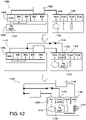
- FIG. 1 illustrates the principle of an electrochemical detection system 10 (e.g., an amperometric electrochemical detection system) according to some embodiments of the present invention for determination of diagnostic clotting times.
- an electrochemical detection system 10 e.g., an amperometric electrochemical detection system
- FIG. 1 illustrates the principle of an electrochemical detection system 10 (e.g., an amperometric electrochemical detection system) according to some embodiments of the present invention for determination of diagnostic clotting times.
- diagnostic clotting time assays e.g., PT, aPTT, and ACT assays
- the micro-environment sensor structures described herein may also be useful for detecting various analytes of potential interest.
- the electrochemical detection system of the present invention is not limited to the assay of coagulation enzymes.
- any assay where an enzyme cleaves a substrate molecule to yield an electroactive moiety can use the present methodology.
- assays can be devised for a variety of other known enzymes in the art, such as for example, glucose oxidase, lactate oxidase, and other oxidoreductases, dehydrogenase based enzymes, and alkaline phosphatase and other phosphatases, and serine proteases without departing from scope of the present invention.
- some aspects of the present invention may include a phosphatase assay where ferrocene with a phosphate moiety is present in a micro-environment sensor layer.
- the enzyme phosphatase present in a sample may permeate the micro-environment sensor and cleave the phosphate groups enabling the liberated ferrocene molecules to be oxidized at the electrode. Accordingly, the measured current may be a function of the rate of the cleavage reaction, and thus, proportional to the phosphatase activity in the sample.
- a fluidic sample 15 e.g., whole blood
- the fluidic sample 15 may be introduced to an analysis region 30 of the cartridge, e.g., a sensor region or one or more locations within one or more conduits of the cartridge that includes one or more sensors for coagulation detection and optionally for detection of a target analyte (e.g., thrombin activity for a prothrombin time and troponin I).
- the analysis region 30 includes one or more micro-environment sensors 35 comprising one or more electrodes or transducers 37, one or more reagents 40, and one or more substrates 45 in any number of different possible arrangements.
- the form and orientation of the electrodes, reagents, and substrate may vary widely depending on the embodiment of the invention, which are described in detail hereafter.
- the one or more reagents 40 may include a material for inducing coagulation via the intrinsic or extrinsic pathway.
- Materials suitable for inducing the extrinsic pathway e.g., PT analysis
- a variety of other components may be included within the one or more reagents 40 to contribute to stabilization and deposition/dissolution characteristics of the one or more reagents 40.
- the one or more reagents 40 may further comprise one or more components selected from the group consisting of carrier proteins such as bovine serum albumin (BSA), stabilizing agents, antimicrobial agents, a calcium salt, a potassium salt, a water soluble polymer, a sugar, gelatin, agarose, a polysaccharide, a saccharide, sucrose, polyethylene glycol, sodium phosphate, glycine, an amino acid, antioxidants, a detergent, a buffer salt, and a buffer such as 4-(2-hydroxyethyl)-1-piperazineethanesulfonic acid (HEPES) buffer.
- BSA bovine serum albumin
- stabilizing agents such as sodium salt, a potassium salt, a water soluble polymer, a sugar, gelatin, agarose, a polysaccharide, a saccharide, sucrose, polyethylene glycol, sodium phosphate, glycine, an amino acid, antioxidants, a detergent, a buffer salt, and a buffer such as
- the one or more reagents 40 may include material suitable for inducing the intrinsic pathway.
- Materials suitable for inducing the intrinsic pathway e.g., the aPTT or ACT analysis
- a variety of other components may be included within the one or more reagents 40 to contribute to stabilization and/or deposition/dissolution characteristics of the one or more reagents 40.
- the one or more reagents 40 may further comprise one or more components selected from the group consisting of dextran, cyclodextrin, dextrin, tergitol, buffers, a carrier protein, an amino acid, stabilizers, antimicrobials, antioxidants, a detergent, a saccharide, a polysaccharide, sucrose, a polyether compound such polyethylene glycol, derivatives of polyethylene glycol, polyethylene oxide or polyoxyethylene, glycine, gelatin, buffer such as 4-(2-hydroxyethyl)-1-piperazineethanesulfonic acid (HEPES) buffer, rhamnose, trehalose, and sugars.
- HEPES 4-(2-hydroxyethyl)-1-piperazineethanesulfonic acid
- the one or more substrates 45 used in the electrogenic assay may have an amide linkage that mimics the thrombin-cleaved amide linkage in fibrinogen.
- the one or more substrates 45 may comprise one or more thrombin-cleavable peptides such as those selected from the group consisting of H-D-Phe-Pip-Arg, H-D-Chg-Abu-Arg, CBZ-Gly-Pro-Arg, Boc-Val-Pro-Arg, H-D-Phe-Pro-Arg, Cyclohexylglycine-Ala-Arg, Tos-Gly-Pro-Arg, Bz-Phe-Val-Arg, Boc-Val-Pro-Arg, Ac-Val-Pro-Arg, Ac-Val-Hyp-Arg, Ac-(8-amino-3,6,dioxaoctanoyl-Val-Pro-Arg, Ac-Gly-Pro-Arg, Ac-(8-amino-3,6,dioxaoct
- Thrombin typically cleaves the amide bond at the carboxy-terminus of the arginine residue because the bond structurally resembles the thrombin-cleaved amide linkage in fibrinogen.
- the product of the thrombin-substrate reaction includes electrochemically inert compounds such as Tos-Gly-Pro-Arg, H-D-Phe-Pip-Arg, and/or Bz-Phe-Val-Arg- and electroactive compounds or detectable moieties, preferably selected from the group consisting of p-aminophenol, a quinone, a ferrocene, ferrocyanide derivative, other organometallic species, p-nitroaniline, o-dianisidine, 4,4'-bensidine, 4-methoxy-2-naphthylamine, N-phenyl-p-phenylenediamine, N-[p-methoxyphenyl-]-p-phenylenediamine, and phenazine derivatives
- the tripeptide sequence was chosen because it renders the substrate virtually non-reactive with blood proteases other than thrombin and the reactivity of thrombin with the arginine amide linkage in the molecule is very similar to its reactivity with the target amide linkage in fibrinogen.
- generated active thrombin from activation of the coagulation pathway(s) via the one or more reagents 40 simultaneously converts the one or more substrates 45 and fibrinogen to their cleavage products.
- the electrochemical species reaction product is detected by the one or more transducers 37, e.g., an electrochemical transducer.
- micro-environment sensor structures comprise one or more reagents and one or more substrates in any of a number of different arrangements such that the introduction of the fluid sample, e.g., whole blood, to the one or more reagents and the one or more substrates is localized to the one or more sensors.
- the micro-environment sensor structures are configured to physically separate the one or more reagents and/or reaction products from one another to avoid cross-activation of the cascade pathways or other cross-sensor interference once the one or more reagents have become exposed to the fluid sample.
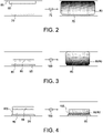
- reagent/substrate 60 printed as a dry substance on a wall 65 (e.g., a cover) of a conduit that is opposite a surface of a sensor 70.
- the fluid sample 75 would need to be mixed with the dry substance, e.g., by pump oscillation, to dissolve the reagent/substrate 60 into the fluid sample 75 and generate a mixture 80, which may be in the form of a gradient from a top of the conduit down to the sensor 70.
- a mixture 80 which may be in the form of a gradient from a top of the conduit down to the sensor 70.
- such a configuration has at least three issues or disadvantages.
- the reagent/substrate 60 should be dispersed uniformly in the fluid sample 75 as rapidly as possible. This may be a challenge for point-of-care devices where space and efficiency of mixing can be limited.
- the reagent/substrate 60 is in solid form and in a very small space relative to a volume of the fluid sample 75.
- the substrate interferes with the reagent and/or coagulation factors. For example, mixing the substrate along with the reagent into the sample 75 before the coagulation cascade has been initiated may manifest such interference.
- some embodiments of the present invention present the reagent 85 associated with a substrate layer 90 formed in a localized manner near the surface of the sensor 95.
- the reagent 85 and the substrate 90 may be printed as a dry substance directly on a surface of the sensor 95.
- the fluid sample 100 may react with the reagent 85 and the substrate 90 without mixing (e.g., via passive diffusion) (although some degree of mixing, e.g., fluid oscillation, may be desired), in a localized manner creating a gradient from the sensor 95 to a top of the conduit.
- this arrangement of the reagent and the substrate presented directly on a surface of the sensor allows for a majority of the electroactive product to be oxidized, and thus utilized at the surface of the sensor.
- This sensor arrangement is also beneficial due to the smaller sample volume required in the immediate sensor environment, and thus yielding a more concentrated reagent-to-sample assay zone.
- any reaction occurring in the immediate vicinity of the sensor could potentially interfere with the reagent and/or coagulation factors and/or possibly with another reaction occurring at an adjacent sensor (i.e., a sensor within the same conduit and within approximately 3 mm of the sensor shown in FIG. 3 ).
- this type of sensor arrangement would not be characterized as a micro-environment sensor.
- micro-fluidic systems of the present invention e.g., splitting a single sample into two or more parts and controlling movement of those parts into two or more conduits or conduits
- appropriate spacing of sensors from one another e.g., in some embodiments, where adjacent sensors are covered by a same quiescent sample fluid, to prevent cross-sensor interference below a given threshold, e.g., below 1%, it may be suitable to use models based on a known diffusion coefficient for the interferent and the overall assay time to determine an appropriate separation distance between sensors.
- a given threshold e.g., below 1%
- models for dynamic mixing may be suitable for use to select an appropriate sensor separation distance.
- the immobilization may be realized by crosslinking (e.g., ultra-violet light, glutaraldehyde, etc.), entrapment, covalent binding, etc.
- crosslinking e.g., ultra-violet light, glutaraldehyde, etc.
- entrapment e.g., covalent binding
- FIG. 4 One example of such a microenvironment arrangement is shown in FIG. 4 where the substrate 90 is immobilized on the surface of the sensor 95 using a polymer layer 105.
- the immobilization may be performed by coating the sensor 95 with a polymer layer 105 that includes the substrate 90 such that the substrate 90 is immobilized via the polymer layer 105 on the surface of the sensor 95.
- the substrate 90 is formed as an immobilized porous substrate-polymer layer on the surface of the sensor 95 to create a vessel for maintaining the reaction of the fluid sample 100, the reagent 85, and the substrate 90 in a localized manner on a surface of the sensor 95.
- the fluid sample 100 may react with the reagent 85 and the substrate 90 without mixing (although some degree of mixing, e.g., fluid oscillation, may be desired) in a localized manner within the confines of (or above, and then diffused into) the polymer layer 105 formed on the sensor.
- this arrangement of the immobilized substrate presented directly on a surface of the sensor allows for a majority of the electroactive product to be oxidized, and thus utilized at the surface of the sensor.
- this arrangement of the immobilized substrate provides for a micro-environment capable of maintaining the substrate and the electroactive product in the immediate vicinity of the sensor, and thus mitigating cross-sensor interference with an adjacent sensor during normal usage.
- Other potential benefits of immobilizing the substrate on the sensor include mitigation of substrate interference via separation of the substrate from the reagent, reduction of material use, simplification of hardware and sensor design, and improvement of product robustness.
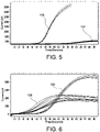
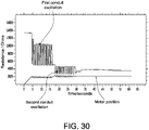
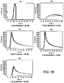
- FIGS. 5 and 6 provide empirical evidence that immobilizing the substrate can increase the response current and improve precision of analyte detection significantly.
- FIG. 5 shows aPTT response curves where the x-axis is time/seconds and the y-axis is current/pA.
- the substrate was printed on a sensor, one immobilized with PVA (aPTT response curves 106) and the other not immobilized (aPTT response curves 107).
- An aPTT reagent was spiked into the whole blood. After mixing for about 30 seconds the sample was drawn from the sample tube and filled into cartridges for testing.
- the electric current of the immobilized substrate sensor was over 30 nA, whereas that of the non-immobilized substrate sensor (aPTT response curves 107) was only about 3 nA.
- Their coefficient of variations of tMid time at which the current reaches its middle point
- tMid time at which the current reaches its middle point
- FIG. 6 Another example is shown in FIG. 6 where the x-axis is time/seconds and the y-axis is current/pA.
- the PT response curves 108 represent the response of a non- immobilized substrate sensor to an i-STAT ® PT control fluid level 2
- the PT response curves 109 represent the response of an immobilized substrate sensor to the same i-STAT ® PT control fluid level 2.
- both the substrate and the reagent were printed together on the electrode, and mixed together with the sample during testing.
- the immobilized substrate sensor the substrate was immobilized with PVA on the electrode and the reagent was printed on top of the immobilized substrate, and there was no mixing during test.
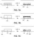
- the micro-environment sensors of the present invention may have the reagent 110 and the immobilized substrate-polymer layer 115 positioned in a number of different arrangements with the components interacting with each other without mixing, although some degree of oscillation may be desired.
- the reagent 110 may be positioned within or encapsulated by the immobilized substrate-polymer layer 115 (e.g., the reagent is integrated within the immobilized substrate-polymer layer).
- the immobilized substrate-polymer layer 115 e.g., the reagent is integrated within the immobilized substrate-polymer layer.
- the reagent 110 may be coated over the immobilized substrate-polymer layer 115 (e.g., the reagent is a separate layer dispensed on top of the immobilized substrate-polymer layer).
- the reagent 110 may be positioned substantially adjacent to the immobilized substrate-polymer layer 115 and at least one transducer of the sensor 120 (e.g., the reagent is positioned within the conduit such that the reagent is abutted to or within an interactive distance of the substrate-polymer layer and/or the at least one transducer so as to still function in conjunction with each other).
- an interactive distance means less than a longest dimension of the sensor with the constraint of the reagent being positioned within a same plane or on a same wall/surface of a conduit as the sensor.
- the reagent 110 may be formed as a combination of that shown in FIGS. 7B and 7C , or as shown in FIG. 7C with only part of the reagent 110 shown in FIG. 7B .
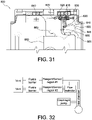
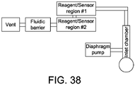
- the present invention may be directed to an analysis cartridge 125 comprising an inlet chamber 130 configured to receive a fluid sample 135 and a conduit 140 fluidically connected to the inlet chamber 130 and configured to receive the fluid sample 135 from the inlet chamber 130.
- the conduit 140 may comprise an array of micro-environment sensors, e.g., a first micro-environment sensor 145 and a second micro-environment sensor 150.
- the first micro-environment sensor 145 may comprise a first reagent 155 and a first substrate 160 (e.g., a substrate immobilized within a polymer layer) configured to detect a first diagnostic clotting time.
- the first micro-environment sensor 145 may be a PT sensor comprising a first reagent 155 that includes one or more components, as discussed herein, specific for triggering the extrinsic coagulation pathway and a first substrate layer 160 comprising a thrombin-cleavable peptide with a detectable moiety as discussed herein.
- the second micro-environment sensor 150 may comprise a second reagent 165 and a second substrate 170 (e.g., a substrate immobilized within a polymer layer) configured to detect a second diagnostic clotting time.
- the second micro-environment sensor 150 may be an aPTT sensor comprising a second reagent 165 that includes one or more components, as discussed herein, specific for triggering the intrinsic coagulation pathway and a second substrate layer 170 comprising a thrombin-cleavable peptide with a detectable moiety (e.g., a reagent and a substrate immobilized within a polymer layer).
- a detectable moiety e.g., a reagent and a substrate immobilized within a polymer layer.
- the first micro-environment sensor 145 may be a PT sensor, and the second micro-environment sensor 150 may be an aPTT sensor.
- the first micro-environment sensor 145 is an aPTT sensor
- the second micro-environment sensor 150 is a PT sensor or an ACT sensor.
- the first micro-environment sensor 145 is an ACT sensor
- the second micro-environment sensor 150 is an aPTT sensor.
- one of the micro-environment sensors is an aPTT sensor
- another of the sensors is a sensor for detecting an analyte, related or unrelated to coagulation.
- the micro-environment sensor structures of the present invention are configured to physically separate the one or more reagents and substrates to avoid cross-activation and/or interference of the cascade pathways once the one or more reagents and substrates have become exposed to the fluid sample.
- incorporation of the immobilized substrate and/or reagent polymer layer into the coagulation assays provides for the ability to perform the coagulation assays without requiring or while minimizing mixing, e.g., oscillation of the sample fluid in a conduit, because coagulation activation occurs in a localized and concentrated area over the sensor with subsequent propagation of the test reaction into the immobilized layer, ultimately resulting in oxidation at the transducer.
- an immobilized substrate and/or reagent-polymer layer may be selectively patterned onto the sensors (e.g., coated over the transducer or working electrode/optical detector).
- the immobilized polymer layer 175 may be formed by either spin coating or by microdispensing.
- an aqueous polymer matrix comprising one or more reagents and substrates and a polymer, such as a photoformable polymer (e.g., polyvinylalcohol (PVA)), may be utilized for immobilizing the one or more substrates on or near the transducer 180.
- a polymer such as a photoformable polymer (e.g., polyvinylalcohol (PVA)
- PVA polyvinylalcohol
- the addition of some substances to the polymer layer(s) results in a number of alterations to, including but not limited to, swelling reactions, diffusion coefficients, molecule stability, porosity, transport, reaction kinetics and the like. These alterations can be used to modulate the micro-environment sensor response as required.
- the one or more substrates may comprise one or more thrombin-cleavable peptides selected from the group consisting of H-D-Phe-Pip-Arg, H-D-Chg-Abu-Arg, CBZ-Gly-Pro-Arg, Boc-Val-Pro-Arg, H-D-Phe-Pro-Arg, Cyclohexylglycine-Ala-Arg, Tos-Gly-Pro-Arg, Bz-Phe-Val-Arg, Boc-Val-Pro-Arg, Ac-Val-Pro-Arg, Ac-Val-Hyp-Arg, Ac-(8-amino-3,6,dioxaoctanoyl-Val-Pro-Arg, Ac-Gly-Pro-Arg, Ac-(8-amino-3,6,dioxaoctanoyl-Gly-Pro-Arg, Ac-Gly-Hyp-Arg and H-D-Chg-Abu-Arg.
- the polymer that contains the substrate may comprise one or more materials, optionally in matrix form.
- the material for the polymer may be selected from the group consisting of PVA, styrylpyridinium polyvinylalcohol (SBQ-PVA), agarose, polyacrylamide, polymethyl methacrylate, N-methylpyrrolidone, polyvinylpyrrolidone, polyimide, a film-forming latex, sepharose TM , polyurethanes, acrylates, methacrylates, polyethylene glycols, polylactic acid, poly(lactic co-glycolic acid), hydroxypropyl cellulose, celluloses, derivatives of cellulose, hydroxypropylmethylcellulose acetate succinate, inulin, fructans, derivatives of fructans, polyglycolic acid, Elvace TM , carboxymethyl cellulose, polylactic acid, and poly(lactic co-glycolic acid).
- the material for the polymer comprises celluloses (e.g., hydroxypropyl cellulose)
- additives such as a plasticizer (e.g., triethyl citrate, acetyl triethyl citrate, propylene glycol, glycerin, trimethylolpropane, polyethylene glycols, fatty acids, and derivatives thereof) and/or crosslinkers (e.g., carboxylic acids, glyoxal, and any resin which is reactive with the available hydroxyl groups of the cellulose) may also be included in the aqueous matrix.
- Crosslinking of the materials may also affect the polymer layer swelling, permeability, diffusion, reaction kinetics etc. in order to modulate the sensor response as required.
- another benefit of immobilizing the substrate and/or reagent includes using the immobilizing matrix as a localized interferant neutralizer.
- the selection of the material for the polymer may be dependent upon the type of diagnostic clotting test to be performed using the immobilized polymer layer.
- inclusion of cross-linked or non-cross-linked SBQ-PVA in the immobilized polymer layer imparts a heparin neutralizing property or heparin insensitivity into the immobilized polymer layer.
- the polymer may be selected to be a heparin-neutralizing polymer such as cross-linked or non-cross-linked SBQ-PVA.
- the PVA may be a photo-activated stilbizonium salt.
- FIGS. 10 and 11 exemplify this concept as follows.
- a coagulation sensor was directly printed either with a large ( FIG. 10 ) or small ( FIG. 11 ) SBQ-PVA immobilized coagulation substrate.
- a PT coagulation activator was printed on top of the immobilized substrate matrix.
- FIG. 10 and 11 (response curves 181) (heparin spike) should be more similar to response curves 182 (abnormally long control fluid) clotting times, but are actually behaving more like whole blood without heparin, (response curves 183)).
- response curves 182 abnormally long control fluid
- response curves 183 heparin neutralizing effect of a polymer such as SBQ-PVA.
- applying a larger amount of the immobilizing matrix results in a greater neutralizing effect (e.g., compare the bias between whole blood and whole blood with heparin in FIGS. 10 and 11).
- FIG. 10 data represents a large matrix print and shows that there is 14% extension when heparin is added to 1 IU/mL, while in FIG.
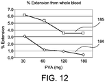
- FIG. 12 provides further empirical evidence that a cross-linked SBQ-PVA may be used to impart a heparin neutralizing property or heparin insensitivity to an immobilized substrate PT assay.
- FIG. 12 shows results of a PT assay performed on a whole blood sample (response curve 184) and a whole blood sample (response curve 185) spiked with 0.4 (response curve 184) or 1.2 IU/ml (response curve 185) of heparin without use of heparinase (a reagent conventionally included in a PT test for neutralizing heparin), but with the addition of increasing amounts of SBQ-PVA to the same size print.
- the data shows that increasing the concentration of the SBQ-PVA layer results in the lowering of the clotting time extensions from whole blood in the presence of heparin. This shows that the PT micro-environment sensor response can be modulated to reduce interference of heparin without the use of expensive heparinase.
- a positive charge imparted by the cross-linked or non-cross-linked SBQ-PVA may impart the heparin neutralizing property or heparin insensitivity to the immobilized substrate PT assay.
- the SBQ pendent group is a cation
- the PVA is an anion
- the heparin is an anion
- an anionic polymer such as hydroxypropyl cellulose may be used for diagnostic clotting time tests that monitor heparin therapy (e.g., aPTT and ACT) without imparting a heparin neutralizing property or heparin insensitivity to the assay.
- the polymer may be a non-heparin neutralizing polymer that could then be subsequently treated or modified to become heparin neutralizing.
- the polymer may be selected to include at least one non-heparin neutralizing component, for example, selected from the group consisting of hydroxypropyl cellulose, and Elvace TM , carboxymethyl cellulose, polylactic acid, polylactic acid, poly(lactic co-glycolic acid), celluloses, derivatives of cellulose, hydroxypropylmethylcellulose acetate succinate, inulin, fructose, fructans, derivatives of fructans, and polyglycolic acid.
- the one or more components of the non-heparin neutralizing polymer may then be treated or modified to generate a heparin neutralizing layer.
- the treatment or modification may include changing the charge of the one or more components of the non-heparin neutralizing polymer, adding heparinase to the polymer matrix, and/or configuring the polymer layer to preferentially bind sulfate groups on the heparin.
- the polymer may be formed of a non-heparin neutralizing polymer.
- the polymer layer may include at least one non-heparin neutralizing component optionally selected from the group consisting of hydroxypropyl cellulose, Elvace TM , carboxymethyl cellulose, polylactic acid, polylactic acid, poly(lactic co-glycolic acid), celluloses, derivatives of cellulose, hydroxypropylmethylcellulose acetate succinate, inulin, fructans, derivatives of fructans, and polyglycolic acid.
- the immobilized substrate and/or reagent polymer layer may be photolithographically patterned using ultraviolet light to crosslink the material using a mask followed by removal of the non-crosslinked material such that the immobilized substrate and/or reagent polymer layer is selectively coated.
- an appropriate quantity of each coating may be applied to an area optionally circumscribed by an additional structural component configured as a containment boundary.
- surfaces treatments e.g., exposure to gas plasmas, may be used to control the surface energy, and thus the spreading of the microdispensed material.
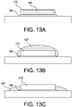
- the one or more reagents and substrates 187 may be immobilized within the polymer layer 175 as shown in FIG. 13A .
- the aqueous substrate-polymer-reagent matrix comprising one or more substrates, a polymer such as photoformable polymer (e.g., PVA), and one or more reagents may be utilized for immobilizing the one or more substrates and the one or more reagents on or near the transducer 180.
- the immobilized polymer layer 175 may be formed by either spin coating or by microdispensing the aqueous substrate-polymer-reagent matrix.
- the one or more reagents or substrates 187 for an aPTT or ACT test may be immobilized within the polymer layer 175 and the dried volume of the immobilized reagent-substrate-polymer layer 175 comprising the one or more reagents or substrates 187 may be in the range of about 0.55 - 2.0 nL, preferably in the range of about 1.0 -1.5 nL.
- the immobilized polymer layer 175 is substantially planar and has a thickness in the range of about 0.1- 100 ⁇ m.
- the immobilized polymer layer 175 is substantially domed and has a maximum thickness of the dome in the range of about 0.1- 100 ⁇ m.
- the reagents are shown in FIG. 13A heterogeneously localized in the central region of the polymer layer 175, in preferable embodiments the reagent(s) is homogeneously dispersed throughout the substrate-polymer layer.
- the one or more reagents or substrates 187 may be formed as a separate layer over and/or adjacent to the immobilized polymer layer 175 as shown in FIGS. 13B and 13C . Further, the one or more regents or substrates may be localized/immobilized together or in separate locations. In accordance with these aspects of the present invention, the one or more reagents or substrates 187 may be spin coated or printed over and/or adjacent to the immobilized polymer layer 175 (e.g., the PVA layer) to localize electrochemical or optical signals over or near the transducer 180.
- the immobilized polymer layer 175 e.g., the PVA layer
- the one or more reagents or substrates 187 for a PT test may be formed separate from the immobilized polymer layer 175 and the dried volume of the immobilized polymer layer 175 may be in the range of 1.5 - 2.2 nL, preferably in the range of 1.60 - 2.00 nL.
- the immobilized polymer layer 175 is substantially planar and has a thickness in the range of about 0.1- 100 ⁇ m. In additional or alternative embodiments, the immobilized polymer layer 175 is substantially domed and has a maximum thickness of the dome in the range of about 0.1- 100 ⁇ m.
- a preferred embodiment of a microfabricated sensor array comprises at least one transducer (e.g., a working electrode or optical detector).
- the microfabricated sensor array may comprise a pair of micro-environment sensors or transducers comprising a first micro-environment sensor or transducer (e.g., an aPTT) and optionally a second microenvironment sensor or transducer (e.g., a PT sensor sensor).
- the microenvironment sensors or transducers may be fabricated as adjacent structures, respectively, on a silicon chip.
- the microfabricated sensor array may further comprise in addition to the first microenvironment sensor or transducer and optionally the second micro-environment sensor or transducer, one or more blood chemistry sensors.
- the sensor array may further comprise one or more of sensors configured to measure one or more of sodium, potassium, calcium, chloride, carbon dioxide, glucose, blood urea nitrogen (BUN), creatinine, pH, partial pressure CO 2 , partial pressure O 2 , lactate, magnesium, or another analyte.
- the transducers may be formed as electrodes with gold surfaces coated with a photo defined polyimide layer.
- wafer-level micro-fabrication of a preferred embodiment of the sensor array may be achieved as shown in FIG. 14 .
- a planar non-conducting substrate 190 may be used as a base for the sensor array.
- a conducting layer 195 may be deposited on the substrate 190 by conventional means, e.g., conductive printing, or micro-fabrication technique known to those of skill in the art to form at least one transistor.
- the conducting layer 195 may comprise a noble metal such as gold, platinum, silver, palladium, iridium, or alloys thereof, although other unreactive metals such as titanium and tungsten or alloys thereof may also be used, as many non-metallic electrodes of graphite, conductive polymer, or other materials may also be used.
- a noble metal such as gold, platinum, silver, palladium, iridium, or alloys thereof, although other unreactive metals such as titanium and tungsten or alloys thereof may also be used, as many non-metallic electrodes of graphite, conductive polymer, or other materials may also be used.
- a base electrode may comprise a square array of 5-10 ⁇ m gold disks, e.g., 7 ⁇ m gold disks, on 15 ⁇ m centers.
- the array may cover a region, e.g., a circular region, approximately 300 to 900 ⁇ m in diameter, optionally 400-800 ⁇ m or about 600 ⁇ m in diameter, and may be formed by photo-patterning a thin layer of polyimide or photoresist of thickness up to 1.5 ⁇ m over a substrate made from a series of layers comprising Si,SiO 2 ,TiW, and/or Au, or combinations thereof.
- the base electrode has a working area of about 130,000 to 300,000 sq ⁇ m
- the volume of sample directly over the sensor may be about 0.1-0.3 ⁇ L
- the volume of the sample over the chip may be 1-3 ⁇ L.
- the conduit in a region of the base electrode has a volume to sensor area ratio of less than about 6 ⁇ L to about 1 square mm, preferably less than about 50 mm to about 2 square mm, more preferably less than about 100 ⁇ m to about 500 square ⁇ m. Accordingly, the array of microelectrodes affords high collection efficiency of a detectable moiety that is an electroactive species with a reduced contribution from any electrochemical background current associated with the capacitance of the exposed metal.
- openings in the insulating polyimide or photoresist layer define a region of gold electrodes at which the electroactive species, e.g., p-aminophenol, may be oxidized such as in a two electron per molecule reaction.
- the electroactive species e.g., p-aminophenol
- Micro-fabrication techniques may be utilized for construction of the multilayered sensor structures in confined spaces.
- methods for micro-fabrication of electrochemical immunosensors on silicon substrates are disclosed in U.S. Patent No. 5,200,051 , and include, for example, dispensing methods, methods for attaching substrates and reagents to surfaces including photoformed layers, and methods for performing electrochemical assays.
- the microfabricated sensor array may also comprise an electrical connection 195 and an immobilized polymer layer 205 (as discussed above with respect to FIGS. 4 , 7A, 7B, and 7C ), which is deposited onto at least a portion of the conducting layer 195 and/or the non-conducting substrate 190.
- the immobilized polymer layer 205 may be a porous polymer layer comprising a thrombin-cleavable peptide with a detectable moiety that is configured to respond to the presence of active thrombin by producing a change that is capable of being measured.
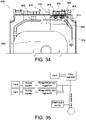
- the microfabricated sensor array may comprise a silicon chip 210 that includes micro-environment amperometric sensors or transducers 215 and 220 located on different vertical planes (a) and (b) of the silicon chip 210.
- the sensor 215 may be connected via wiring 225 to a first amperometric pin 230 (e.g., temporary electrical connector) and the sensor 220 may be connected via wiring 235 to a second amperometric pin 240 (e.g., temporary electrical connector).
- the sensor 215 may be configured as an aPTT sensor and the sensor 220 may be configured as a PT sensor both of which are formed on the single silicon chip 210 and positioned within one or more conduits of the point of care test cartridge.
- the senor 215 may be constructed with a target reticle design preferably comprising a plurality of concentric rings (e.g., 2, 3, 4 or more concentric rings) in an upper area of the silicon chip 210 and the sensor 220 may be constructed with a target reticle design preferably comprising a plurality of concentric rings (e.g., 2, 3, 4 or more concentric rings) in a lower area of the silicon chip 210.
- the design and arrangement of the sensors 215 and 220 on the chip 210 are selected based on printing and performance characteristics for each of the sensors 215 and 220.
- sensors 215 and 220 in the example in FIG. 15 are amperometric sensors, other electrochemical processes or optical processes which use other electrochemical or optical sensors, e.g., optical wave guides and charge-coupled device (CCD) camera chips, can be used.
- a potentiometric sensor may be used to detect ion species such as Na + or K + .
- the amperometric sensors or transducers 215 and 220 may be formed as electrodes with gold surfaces that are exposed (e.g., no polyimide or photoresist covering) to the inside environment of the conduit and configured to directly contact a biological sample disposed within the conduit.
- the wirings 225 and 235 may be formed with gold surfaces that are coated with a photo defined polyimide or photoresist layer such that the wirings 225 and 235 are insulated from exposure to the biological sample disposed within the conduit.
- the wirings 225 and 235 may be formed comprising containment ring structures 245 and 250 configured to contain the immobilized reagent-substrate-polymer layer.
- the immobilized reagent-substrate-polymer layer may be deposited onto at least a portion of the sensors 215 and/or 220 within the containment ring structures 245 and/or 250.
- the wirings 225 and 235 terminate at the first amperometric pin 230 and the second amperometric pin 240 respectively, which are used to make contact with a connector in an analyzer or cartridge reader (e.g., an i-STAT ® cartridge reader as described in U.S. Patent No. 4,954,087 ).
- the analyzer applies a potential via the first amperometric pin 230 and the second amperometric pin 240 between each of the amperometric sensors 215 and 220 and a reference electrode (described in detail below with respect to FIG. 17 ), and measures current changes generated by cleaved substrate as an electrochemical signal.
- the electrochemical signal being proportional to the concentration of the product in the biological sample.
- the amperometric sensors 215 and 220 have an applied potential of approximately +0.4 V versus the reference electrode and, in another preferred embodiment, the amperometric sensors 215 and 220 have an applied potential of approximately +0.1 V versus the reference electrode.
- the signal generated by the enzyme reaction product at approximately +0.1V is distinguishable from the signal generated by the unreacted substrate at approximately +0.4 V.
- the thrombin cleavable peptide Tos-Gly-Pro-Arg-, H-D-Phe-Pip-Arg, or Bz-Phe-Val-Arg attached to an N-phenyl-p-phenylenediamine or N-[p-methoxyphenyl-]-p-phenylenediamine detectable moiety the intact substrates are detected at a voltage of approximately +0.4V.
- the electrogenic reaction products N-phenyl-p-phenylenediamine or N-[p-methoxyphenyl-]-p-phenylenediamine are detected at a voltage of approximately +0.1V.
- the analyzer applies a potential to the amperometric sensors 215 and 220 with the generation of an electrochemical signal which is proportional to the concentration of the substrate in the biological sample. Also, the analyzer applies a potential to the amperometric sensors 215 and 220 with the generation of an electrochemical signal which is proportional to the concentration of the product in the biological sample. After hydrolysis of the substrate by thrombin, a product is formed which reacts at the amperometric sensors 215 and 220 with the generation of a signal distinguishable from the signal generated by the substrate.
- the exact voltages used to amperometrically detect the substrate and the product will vary depending on the chemical structure of the substrate and product. It is important that the difference in the voltages used to detect the substrate and the product be great enough to prevent interference between the readings. With some substrates, the voltage required to electrochemically detect the substrate is so high as to be beyond practical measurement in an aqueous buffered solution. In these cases, it is only necessary that the product be detectable amperometrically.
- the silicon chip 210 shown in FIG. 15 may further include multi-conduit conductometric sensors 255 and 260 (e.g., hematocrit sensors).
- the conductimetric sensors 255 and 260 are configured to determine biological sample arrival and/or departure at the amperometric sensors 215 and 220. More specifically, the conductometric sensors 255 and 260 lie perpendicular to a length of the conduit or sensor conduit, and an electrical resistance between pairs of electrodes for each sensor may be used to monitor a relative position of a fluid front of the biological sample. At the extremes, an open circuit reading indicates that the biological sample has been pushed off the amperometric sensors 215 and 220 and a closed circuit reading indicates the amperometric sensors 215 and 220 are covered with the biological sample.
- the conductometric sensor 255 may comprise at least two electrodes 265 and 270 (i.e., first electrode pair) positioned upstream of a midpoint of the amperometric sensor 215.
- the electrodes 265 and 270 may be connected via wirings 275 and 280 to a conductometric low pin 285 and an AC source or conductometric high pin 290, respectively (e.g., temporary electrical connectors).
- the wirings 275 and 280 may be formed with a gold surface that is coated with a photo defined polyimide or photoresist layer such that the wirings 275 and 280 are insulated from exposure to the biological sample disposed within the conduits.
- the conductometric sensor 260 may comprise at least two electrodes 295 and 300 (i.e., second electrode pair) positioned downstream of a midpoint of the amperometric sensor 220.
- the electrodes 295 and 300 may be connected via wirings 275 and 280 to a conductometric low pin 285 and an AC source or conductometric high pin 290, respectively (e.g., temporary electrical connectors).
- the fluid reaches the first electrode pair in a first fluidic conduit (e.g., prior to arriving at amperometric sensor 215), then subsequently arrives at the second electrode pair in a second fluidic conduit (e.g., after arriving at amperometric sensor 220).
- the silicon chip 210 may further include a third conductometric sensor 301 comprising at least two electrodes 302 and 303.
- the electrodes 302 and 303 may be connected via wiring 304 to a second AC source or conductometric high pin 305 (e.g., temporary electrical connector).
- a third sensor allows for two binary fluid detection events, e.g., both are OFF/ON, which is easily detectable with the current circuitry and software limitations.
- the current circuitry and software relies on the ability to detect two 'drops' in the resistance of the sample in quick succession.
- the arrangement of having three conductometric sensors allows for two switchable conductivity paths using the conductometric sensor 255 (shown in FIG. 15 ) and the conductometric sensor 301 (shown in FIG. 16 ).
- the microfabricated sensor array may further comprise a ground chip 306 that includes a reference sensor or electrode 307.
- the reference electrode 307 may be configured as a counter electrode to complete the circuitry.
- the reference electrode 307 may comprise silver metal (Ag) and its silver salt (AgCl) deposited on a solid substrate (i.e., an Ag/AgCl reference electrode).
- the reference electrode 307 may be connected via wiring 308 to a reference pin 309 (e.g., temporary electrical connector).
- the microfabricated sensor array may be designed such that the ground chip 306 is positioned upstream of the semiconductor chip 210 as discussed in further detail with respect to FIGS. 15 and 16 .
- the sensor array may further comprise one or more additional sensor chips (not shown) configured to detect various analytes of potential interest, such as troponin I, troponin T, CKMB, procalcitonin, bHCG, HCG, NTproBNP, proBNP, BNP, myoglobin, parathyroid hormone, d-dimer, NGAL, galectin-3, and/or PSA, among other analytes.
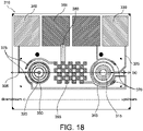
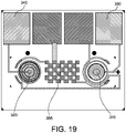
- the microfabricated sensor array may comprise a silicon chip 310 that includes micro-environment amperometric sensors or transducers 315 and 320 located on a same vertical plane (a) of the silicon chip 310.
- the sensor 315 may be connected via wiring 325 to a first amperometric pin 330 (e.g., temporary electrical connector) and the sensor 320 may be connected via wiring 335 to a second amperometric pin 340 (e.g., temporary electrical connector).
- the sensor 315 may be configured as an aPTT sensor and the sensor 320 may be configured as a PT sensor both of which are formed on a single chip 310 and positioned within the conduit of the point of care test cartridge. As illustrated in FIG.
- the sensor 315 may be constructed with a donut shaped design in an upstream position to that of the sensor 320 constructed with a target reticle design comprising a plurality of concentric rings (e.g., 2, 3, 4 or more concentric rings).
- the design and arrangement of the sensors 315 and 320 on the chip 310 are selected based on printing and performance characteristics for each of the sensors 315 and 320.
- any design or arrangement for the sensors is contemplated without departing from the spirit and scope of the present invention.
- the sensors 315 and 320 in the example in FIG. 18 are amperometric sensors, other electrochemical processes or optical processes which use other electrochemical or optical sensors can be used.
- a potentiometric sensor may be used to detect ion species such as Na + or K + .
- the sensors or transducers 315 and 320 may be formed as electrodes with gold surfaces that are exposed (e.g., no polyimide or photoresist covering) to the inside environment of the conduit and configured to directly contact a biological sample disposed within the conduit.
- the wirings 325 and 335 may be formed with gold surfaces that are coated with a photo defined polyimide layer such that the wirings 325 and 335 are insulated from exposure to the biological sample disposed within the conduit.
- the wirings 325 and 335 may be formed comprising containment ring structures 345 and 350 configured to contain the immobilized reagent-substrate-polymer layer.
- the immobilized reagent-substrate-polymer layer (as discussed above with respect to FIGS.
- the wirings 325 and 335 terminate at the first amperometric pin 330 and the second amperometric pin 340 respectively, which are used to make contact with a connector in an analyzer or cartridge reader (e.g., an i-STAT ® cartridge reader as described in U.S. Patent No. 4,954,087 ).
- an analyzer or cartridge reader e.g., an i-STAT ® cartridge reader as described in U.S. Patent No. 4,954,087 ).
- the silicon chip 310 further includes an integrated reference electrode 355.
- the reference electrode 355 is configured as a counter electrode to complete the circuitry.
- the reference electrode 355 may comprise silver metal (Ag) and its silver salt (AgCl) deposited on a solid substrate (i.e., a Ag/AgCl reference electrode).
- the reference electrode may be connected via wiring 360 to an AC ground and reference pin 365 (e.g., temporary electrical connector).
- the wiring 360 may be formed with a gold surface that is coated with a photo defined polyimide or photoresist layer such that the wiring 360 is insulated from exposure to the biological sample disposed within the conduit.
- the reference electrode 355 is designed in a checkerboard pattern as illustrated in FIG. 18 to improve wettability of a surface of the reference electrode 355. Specifically, it has been found unexpectedly that the wettability of the reference electrode 355 may be improved using the checkerboard pattern because AgCl is relatively hydrophobic and can promote the formation of an air bubble over the surface of the reference electrode 355 when a solid patch of AgCl is used, which results in a poor circuit.
- the analyzer applies a potential via the first amperometric pin 330 and the second amperometric pin 340 between each of the amperometric sensors 315 and 320 and the reference electrode 355, and measures current changes generated by cleaved substrate as an electrochemical signal.
- the electrochemical signal being proportional to the concentration of the product in the biological sample.
- the amperometric sensors 315 and 320 have an applied potential of approximately +0.4 V versus the reference electrode 355 and, in another preferred embodiment, the amperometric sensors 315 and 320 have an applied potential of approximately +0.1 V versus the reference electrode 355.
- the signal generated by the enzyme reaction product at approximately +0.1 V is distinguishable from the signal generated by the unreacted substrate at approximately +0.4 V.
- the silicon chip 310 may further include conductometric sensors 370 and 375 (which can also function as hematocrit sensors).
- the conductimetric sensors 370 and 375 may be split to form two sensor pairs with one at each end of the chip 310.
- the conductimetric sensors 370 and 375 are configured to determine biological sample arrival and/or departure at the amperometric sensors 315 and 320, respectively. More specifically, the conductometric sensors 370 and 375 lie in an arc that is perpendicular to a length of the conduit or sensor conduit, and an electrical resistance between pairs of electrodes for each sensor may be used to monitor a relative position of a fluid front of the biological sample. At the extremes, an open circuit reading indicates that the biological sample has been pushed off the amperometric sensors 315 and 320 and a closed circuit reading indicates the amperometric sensors 315 and 320 are covered with the biological sample.
- the conductometric sensor 370 may comprise at least two electrodes 380 and 385 (i.e., first electrode pair) positioned at a predetermined distance (d1) from one another.
- the conductometric sensor 370 may be positioned on the silicon chip 310 relative to a midpoint (v) of the amperometric sensor 315 (e.g., upstream, downstream, or in-line with the midpoint (v)).
- the electrode 380 may be connected via wiring 390 to an AC source pin 395 (e.g., temporary electrical connector).
- the electrode 385 may be connected via wiring 400, the reference electrode 355, and the wiring 360 to the AC ground and reference pin 365.
- the wirings 390 and 400 may be formed with a gold surface that is coated with a photo defined polyimide or photoresist layer such that the wirings 390 and 400 are insulated from exposure to the biological sample disposed within the conduit.
- the conductometric sensor 375 may comprise at least two electrodes 405 and 410 (i.e., second electrode pair) positioned at a predetermined distance (d2) from one another.
- the conductometric sensor 375 may be positioned on the silicon chip 310 relative to a midpoint (x) of the amperometric sensor 320 (e.g., upstream, downstream, or in-line with the midpoint (x)).
- the electrode 405 may be connected via wiring 415, the reference electrode 355, and the wiring 360 to the AC ground and reference pin 365.
- the electrode 410 may be connected via wiring 420 and the wiring 390 to the AC source pin 395.
- the wirings 415 and 420 may be formed with a gold surface that is coated with a photo defined polyimide or photoresist layer such that the wirings 415 and 420 are insulated from exposure to the biological sample disposed within the conduit.
- the conductometric sensors 370 and 375 are configured to detect arrival of the biological sample within the conduit at the amperometric sensors 315 and 320, respectively. As shown in FIG. 21 , the arrival of the biological sample at the amperometric sensors 315 and 320 may be detected based on determination of a first resistance drop 425 when the biological sample reaches conductivity sensor 370 and a second resistance drop 430 when the biological sample reaches conductivity sensor 375. In additional or alternative embodiments, determination of a rise or spike (not shown) in the resistance at either or both of the conductometric sensors 370 and 375 may be used to detect the presence of an air bubble within the conduit that is positioned over either or both of the amperometric sensors 315 and 320.
- a resistance profile for the conductometric sensors 370 and 375 should preferably provide two well defined resistance drops of roughly equal amplitude.
- conductometric sensors 435 and 440 may be configured as separate bars on opposite ends of the chip near respective amperometric sensors 445 and 450.
- the resistance profile 455 for such a design is found to often include an additional step 460, which is attributable to the sample temporarily stopping on the reference electrode 465 due to the hydrophobic nature of the reference electrode 465. As should be understood, this could make it difficult to decipher the second resistance drop as either the wetting of the reference electrode 465 or the sample arriving at the second conductometric sensor 440. Additionally, the time between the two steps is quite short, making the timing difficult, and the resistance drop of the second arrival is much smaller compared to the first drop, making the detection difficult.
- the chip design implemented in preferred embodiments of the present invention utilizes the conductometric sensors 370 and 375, which are each split to comprise at least two electrodes 380, 385 and 405, 410 spaced apart at predetermined distances (d1) and (d2), respectively.
- the dominant resistance drops 425 and 430 occur at the two pairs of conductometric sensors 370 and 375.
- the conductometric sensors 370 and 375 are placed at a front and rear of the chip to increase a time between the resistance drops 425 and 430 to better differentiate the resistance drops 425 and 430.
- the spacing or predetermined distance (d1) provided between the electrodes 380 and 385 is a value "n" greater than that of the spacing or predetermined distance (d2) provided between the electrodes 405 and 410 such that an amplitude of the second resistance drop 430 is increased over a resistance drop 475 (shown in FIG. 22A ) of the alternative chip design.
- (d1) may be constructed twice as large as that of (d2) to achieve about a 1000 ohm increase in amplitude of the second resistance drop.
- the increase in (d1) over that of (d2) effectively increases the ratio of resistance drops for the chip design shown in FIG. 22B over that of the ratio of resistance drops for the chip design shown in FIG. 22A .
- this increase in resistance drops allows for better detection of the arrival of the biological sample at the conductometric sensors 370 and 375 during an on/forward motor or pump position 480.
- Processes of the present invention may include continually moving the biological sample forward and back over the chip at a controlled velocity. Controlling the time for which the conductometric sensors 370 and 375 remain as open and closed circuits controls the position at which the biological sample changes direction.
- a pneumatic pump within the analyzer may be configured to oscillate the biological sample in the conduit with the trailing edge of the biological sample positioned in the region of the conductometric sensor 370 in order to dissolve the substrate in that portion of the sample near the trailing edge.
- the oscillation may be at a frequency in the range of 0.2 to 10 Hertz for a period in the range of 1 to 100 seconds. In a preferred method, the oscillation may be at a frequency in the range of about 1.5 Hertz for a period of about 20 seconds.
- the oscillation may be at a frequency of about 0.3 Hertz and the amperometric sensors 315 and 320 (as shown in FIG. 20 ) may be configured to generate a signal at each oscillation. If erythrocytes are present in the biological sample, the oscillation may be at a frequency adequate to prevent the settling of erythrocytes on the amperometric sensors 315 and 320.
- the amperometric sensors 315 and 320 determine the concentration of product each time the biological sample is oscillated past the amperometric sensors 315 and 320.
- a first amperometric sensor signal may be stored by the analyzer for each of the amperometric sensors 315 and 320 and subsequent signals from the amperometric sensors 315 and 320 may be stored and compared to the first and other stored signals in order to determine a maximum rate of change in the amperometric sensor signals. These data points may then be analyzed to determine a fixed fraction of a maximum rate of change of the amperometric sensor signals. These data points may thus be used to determine a coagulation parameter of interest for each of the amperometric sensors 315 and 320.
- the sensors or transducers may be formed as an optical detector, e.g. CCD camera chip and optical wave guide.
- the optical detector may either be a detector of fluorescence, chemiluminescence, or bioluminescence emission from the detectable moiety or a detector of absorbance by the detectable moiety.
- the detectable moiety may be an optical dye, a fluorescence emitter, chemiluminescence emitter or a bioluminescence emitter.
- the senor or transducers may be formed as a test strip, e.g., a glucose test strip, as described in U.S. Patent Application No. 13/724,348 .
- a test strip may be included within the cartridges described herein.
- the sample may be manually placed on the test strip and, as such, the microfluidic systems described herein would not need to be included with such embodiments.
- glucose test strip devices can include passive capillary fluidic elements to deliver the sample to a sensor or sensor array. As such, the elements, features, and functionality of a glucose test strip could be adapted to the present invention without departing from the spirit and scope of the present invention.
- the system 500 of the present invention may comprise a self-contained disposable sensing device or cartridge 505 and a reader device or instrument 510 (e.g., an analyzer).
- the cartridge 505 is a single-use device configured to be disposable after the single-use.
- a fluid sample e.g., whole blood
- the cartridge 505 may be inserted into the reader 510 through a slotted opening 520.
- the reader 510 may comprise a processor configured to perform measurements of analyte concentrations, measurements of resistances, identify analytes or sets of analytes that a chip is configured to measure, and/or determinations of diagnostic clotting time within the fluid sample, as discussed herein in further detail. Measurements and determinations performed by the reader 510 may be output to a display 525 or other output device, such as a printer or data management system 530 via a port 535 on the reader 510 to a computer port 540. Transmission can be via Wifi, Bluetooth link, infrared and the like.
- the sensors 545 in the cartridge 505 may be configured to make electrical contact with the reader 510 via an electrical connector 550.
- the connector may be of the design disclosed in jointly owned U.S. Patent No. 4,954,087 .
- the PT and aPTT sensors may be configured to connect with an electrical connector of a test meter within the reader 510 via the the electrical connector 550 (see, e.g., U.S. Patent Nos. 5,096,669 and 4,954,087 ).
- the reader 510 may also include a method for automatic fluid flow compensation in the cartridge 505, as disclosed in jointly owned US Patent No. 5,821,399 .
- the self-contained disposable sensing device or cartridge 555 may comprise a cover 560, a base 565, and a thin-film adhesive gasket (not shown) that is disposed between the base 565 and the cover 560.
- the cartridge 555 may be configured for insertion into the reader 510, and therefore the cartridge 555 may comprise a plurality of mechanical and electrical connections (not shown) for this purpose.
- a feature of the cartridge 555 is that once a fluid or biological sample is loaded within the cartridge 555, analysis of the fluid or biological sample may be completed and the cartridge 555 may be discarded without an operator or others contacting the fluid or biological sample.
- the cover 560 may be made of a rigid material, preferably plastic, and capable of repetitive deformation at flexible hinge regions 570, 575, and 580 without cracking.
- the cover 560 may comprise a lid 585, attached to a main body of the cover 560 by the flexible hinge 570.
- the lid 585 may be secured over an entrance to the sample entry port 595, preventing sample leakage.
- the lid 585 may be held in place by a hook 600.
- the cover 560 may further comprise two deformable members 605 and 610 that are moveable relative to the body of the cover 560, and which may be attached to the cover 560 by the flexible hinge regions 575 and 580.
- the deformable member 610 may be configured to be operated by a first pumping means such that a force is exerted upon an air bladder comprised of cavity 615 and the gasket. Operation of the deformable member 610 displaces fluid within conduits of the cartridge 555.
- the deformable member 605 may be configured to be operated upon by a second pumping means such that a force is exerted upon the gasket, which can deform because of slits cut therein.
- deformation of the gasket may transmit pressure onto a fluid-containing foil pack filled with a fluid, e.g., approximately 130 ⁇ L of analysis/wash solution, a control fluid, or calibrant fluid, located in cavity 620, rupturing the foil pack, and expelling fluid into conduit 625 for subsequent use in other conduits during sample analysis.
- a fluid e.g., approximately 130 ⁇ L of analysis/wash solution, a control fluid, or calibrant fluid
- the fluids may generally be required in a single device that combines coagulation tests with other tests, e.g., a wash fluid in immunoassays for analytes such as BNP and troponin, and a calibrant fluid in chemistry tests such as potassium, creatinine and glucose.
- the deformation of the gasket may transmit pressure onto an air bladder comprised of cavity 620 for displacing fluid within conduits of the cartridge 555.
- the second pumping means may not operate upon the cavity 620, and instead, the cavity 620 may be configured as a waste chamber.
- Additional action in the cartridge 555 generated by mechanisms within the reader 510 (discussed with respect to FIG. 23 ) applied to the cartridge 555 may be used to inject one or more air segments into the fluid or biological sample at controlled positions within the sample holding chamber 590 and conduit 630.
- the air segments may be used to wash a sensor surface of the sensor array and the surrounding conduit 630 with a minimum amount of fluid (e.g., a limited wash cycle in which the volume of wash may be less than fifty times a volume of the fluid or biological sample and/or fewer than three independent cycles of clean wash buffer (e.g., three independent washing steps with fresh wash buffer)), as should be understood by those of ordinary skill in the art of immunoassay procedures.
- the cover 560 may further comprise a hole covered by a thin pliable film.
- pressure exerted upon the film may expel one or more air segments into the conduit 630 through a small hole in the gasket.
- a cross-sectional area of the conduit 630 may be in the range of about 0.1 mm 2 to about 10 mm 2 .
- a lower surface of the cover 560 further comprises sample holding chamber 590, the conduit 630 and another conduit 635 (e.g., a waste conduit).
- the sample holding chamber 590 and the conduit 630 may include one or more constrictions or capillary stops 640 and 642 that control fluid flow by providing resistance to the flow of the fluid or biological sample.
- Optional coatings (not shown), e.g., dry reagent coatings, may provide hydrophobic surfaces on the conduit 630, which together with gasket holes control fluid flow between the sample holding chamber 590 and the conduit 635.
- the sample holding chamber 590 may be configured to connect the sample entry port 595 to the conduit 630 in the assembled cartridge 555.
- the cutaway 645 may house one or more sensor chips 650 comprising at least one sensor 655 (e.g., a PT, aPTT, or ACT micro-environment sensor), or a responsive surface, together with an optional conductimetric sensor or sensors 660.
- the cutaway 665 may house a ground chip 670 comprising a ground electrode 675 if needed as a return current path for an electrochemical sensor, and may also house an optional conductimetric sensor.
- the cutaway 665 and the ground chip 670 may not be included with the cartridge 555.
- a metering means may be provided that comprises the sample holding chamber 590 bounded by the constriction or capillary stop 640 and having along the sample holding chamber 590 length an air entry point 680 from the bladder comprising cavity 615. Air pressure exerted at the entry point 680 drives a metered volume of the sample past the constriction or capillary stop 640. Therefore, a metered volume of sample may be predetermined by a volume of the sample holding chamber 590 between the air entry point 680 and the constriction or capillary stop 640. An amount of the sample corresponding to this volume may be displaced into the conduit 630 when the deformable member 605 is displaced.
- This arrangement may therefore provide a metering means for delivering a metered amount of an unmetered sample into the various downstream conduits of the cartridge 555.
- the metering may be advantageous in some embodiments if quantization of an analyte is required. Thus, an operator may be relieved of accurately measuring the volume of the sample prior to measurement saving time, effort, and increasing the accuracy and reproducibility.
- the invention is a process for using a cartridge to determine diagnostic clotting times in a whole blood sample.
- the process may include introducing an unmetered fluid sample into the sample holding chamber 590 of the cartridge 555 through the sample entry port 595 (as shown in FIG. 24 ).
- Capillary stop 640 prevents passage of the fluid sample into conduit 630 at this stage, and the sample holding chamber 590 is filled with the sample. Lid 585 is closed to prevent leakage of the fluid sample from the cartridge 555.
- the cartridge 555 may then be inserted into the reading device or apparatus 510, as shown in FIG. 23 and further disclosed in U.S. Patent No. 5,821,399 .
- insertion of the cartridge into the reading apparatus 510 activates a mechanism, which punctures the fluid-containing package located in the cavity 620 when the package is pressed against a spike (not shown). Fluid may thereby be expelled into one or more conduits (e.g., conduit 630) arriving in sequence at the sensor region. Thereafter, operation of a pump means (e.g., a pneumatic pump) applies pressure to the air-bladder comprised of cavity 615, forcing air through a conduit into the sample holding chamber 590 at the air entry point 680.
- Capillary stop 640 delimits a metered portion of the original fluid sample. The metered portion of the sample is then expelled through the capillary stop 640 by air pressure produced within air bladder comprised of cavity 615.
- the sample passes into the conduit 630 and into contact with the one or more reagents, the one or more substrates (e.g., an immobilized reagent-substrate-polymer layer), and/or the one or more sensors comprising one or more transducers and optionally the reference electrode located within the cutaway 665.
- the one or more substrates e.g., an immobilized reagent-substrate-polymer layer
- the one or more sensors comprising one or more transducers and optionally the reference electrode located within the cutaway 665.
- the fluid sample may be positioned within the conduit 630 to contact the one or more reagents and/or substrates, the one or more immobilized polymer layers, and/or the one or more sensors, e.g., micro-environment sensors, for a predetermined period of time.
- a cartridge Use of a cartridge is herein illustrated by a specific embodiment in which diagnostic clotting time is determined for a fluid sample, which is introduced into the sample holding chamber of the cartridge followed by cartridge insertion into the cartridge reading device.
- the cartridge reading device makes electrical contact with the electrodes/sensors through pads, and performs certain diagnostic tests.
- the diagnostic tests determine whether fluid or sample is present in the conduits using the conductivity electrodes; determine whether electrical short circuits are present in the electrodes; and ensure that the sensor and ground electrodes are thermally equilibrated to, preferably, 37°C prior to the assay cycle.
- a metered portion of the fluid sample preferably between 4 and 200 ⁇ L, more preferably between 4 and 20 ⁇ L, and most preferably 7 ⁇ L, may be used to carry out the assay, while a sub-volume (between 0.1 and 3.5 uL) thereof may be used to contact the electrodes/sensors.
- the fluid sample is positioned with respect to the sensor region such that a portion of the fluid sample is positioned over the one or more reagents, the one or more substrates (e.g., immobilized polymer layers), and the one or more sensors comprising one or more transducers and the ground electrode.
- the sample may move to a second conduit or area for subsequent mixing or interactions, or become static or become locked within the conduit(s) or cartridge prior to signal generation.
- One or more conductivity sensors on the sensor chip may be used to control these processes as discussed with respect to FIGS. 20 , 21 , 22A, and 22B .
- the amending reagents have time to diffuse into the fluid sample or the fluid sample has time to diffuse into the amending reagents (which could be immobilized in some embodiments) in order to promote activation of the coagulation cascade by one of two pathways to generate thrombin,
- the active thrombin has time to diffuse through a substrate layer, e.g., an immobilized substrate and/or reagent polymer layer, and cleave the thrombin-cleavable peptide
- the activated detectable moiety has time to be detected by the at least one transducer.
- a disposable cartridge configuration for that enables two physically separated tests to be conducted simultaneously or subsequently on a single whole blood sample within the same disposable cartridge.
- the elements of the disposable cartridge configuration include the use of passive fluidic features (e.g., valves, resistances, and fluidic locking elements) in addition to active mechanisms from the analyzer (e.g., a pump) to split the sample into separate conduits/regions such that each sample segment can subsequently be moved to a specific sensor.
- the sample may be inserted into the inlet chamber of the cartridge by a user.
- the cartridge is then closed and inserted into the analyzer.
- the diaphragm pump formed as an air bladder in the cartridge and a mechanical plunger in the analyzer are used to move the sample throughout the cartridge.
- the embodiments of the present invention discussed with respect to FIGS. 25-29 are configured to split a single biological (e.g., whole blood) sample and allow independent mix control of at least two segments of the sample in two conduits where dried reagents and/or substrates specific to each test are located.
- the substrates may or may not be localized (e.g., in accordance with some embodiments, may or may not be immobilized) over the sensor.
- the reagents and/or substrates dissolved into the sample remain within the conduit where they were formed, therefore eliminating any potential cross-interference between the tests. This is an important element of multiplexing for any two tests where chemical or physical interference could be present (e.g., coagulation tests).
- some examples of the present invention pertain to a ground sensor first configuration for a cartridge 700 in which a conduit 705 splits at a junction 707 into a first conduit 710 and a second conduit 715 prior to or upstream of a ground chip 720.
- the second conduit 715 may comprise a constriction or capillary stop 725 and is configured to pass over a lower region of the sensor chip 730 comprising at least one analyte detection electrode (as described with respect to FIGS. 15 and 16 ).
- the first conduit 710 is configured to pass over the ground chip 720 (e.g., ground chip with reference sensor as described with respect to FIG.
- the cartridge 700 may further comprise at least one fluidic lock mechanism 735 (e.g., a membrane sponge valve, a microchannel capillary, or a micro-array valve) positioned within the first conduit 710, and one or more conduits 740 (e.g., vents), which lead from the first conduit 710 and the second conduit 715 to the cavity 747.
- the cavity 747 is configured as a waste chamber (as discussed with respect to FIG. 24 ).
- the one or more conduits 740 may be configured to lead to a waste conduit (as discussed with respect to FIG. 24 ).
- FIG. 26 shows an alternative ground sensor first configuration for a cartridge 750 in which the conduit 755 splits at a junction 760 into a first conduit 765 and a second conduit 770 prior to or upstream of a ground chip 775.
- the second conduit 770 may comprise a constriction or capillary stop 780 and is configured to pass over a lower region of the sensor chip 785 comprising at least one analyte detection electrode (as described with respect to FIGS. 15 and 16 ).
- the first conduit 765 is configured to pass over the ground chip 775 (e.g., ground chip with reference sensor as described with respect to FIG. 17 ) and the upper region of the sensor chip 785 comprising at least one analyte detection electrode (as described with respect to FIGS. 15 and 16 ).
- the cartridge 750 may further comprise at least one fluidic lock mechanism 790 positioned within the first conduit 765. And one or more conduits 793 and 795 (e.g., vents), which lead from the first conduit 765 and the second conduit 770 respectively to a waste conduit 797 (as discussed with respect to FIG. 24 ).
- conduits 793 and 795 e.g., vents
- the fluid or biological sample is moved using the bi-directional diaphragm pump (as described with respect to FIG. 24 ) from the inlet or sample holding chamber to the conduits 705/755.
- the biological sample is split into a first portion and a second portion at the junction 707/760 (e.g., a T-junction).
- the constriction or capillary stop 725/780 positioned within the second conduit 715/770 causes the sample to preferentially fill the first conduit 710/765 and move over the ground chip 720/775 and the at least one electrode (e.g., an aPTT electrode) within the upper region of the sensor chip 730/785.
- the diaphragm pump can therefore move a first portion of the sample back and forth in the first conduit 710/765 to dissolve and mix the reagent and/or substrate into sample, while a second portion of the sample in the second conduit 715/770 neither vacates the second conduit 715/770 nor moves to the sensor chip 730/785.
- the first portion of the sample is pushed over the sensor chip 730/785 to the fluidic lock mechanism 735/790 (e.g., a membrane "sponge valve” or a microchannel formed in either the double-sided adhesive or one of the molded plastic components), which provides pressure resistance and effectively locks the first portion of the sample into the first conduit 710/765.
- the fluidic lock mechanism 735/790 e.g., a membrane "sponge valve” or a microchannel formed in either the double-sided adhesive or one of the molded plastic components
- the second portion of the sample can be positioned over the sensor chip 730/785 and analysis in the second conduit 715/770 can begin.
- the second portion can be moved through the second conduit 715/770 over at least one electrode (e.g., a PT electrode) within the lower region of the sensor chip 730/785.
- the electrodes within the upper and lower region of the sensor chip 730/785 may be formed with or without immobilization of the reagent/substrate using one or more of the arrangements as discussed with respect to FIGS. 2, 3, 4 , 7A, 7B, 7C and 9 .
- the fluid or biological sample may be moved using the bi-directional diaphragm from the inlet or sample holding chamber to the sensor chip 730/785 (as described with respect to FIG. 24 ). Additionally, once the reagent and/or substrate is mixed into the second portion of the sample, the second portion of the sample is pushed over the sensor chip 730/785 to an additional fluidic lock mechanism 745/798 (shown in FIGS. 25 and 26 ) (e.g., a membrane "sponge valve" or a microchannel formed in either the double-sided adhesive or one of the molded plastic components), which provides pressure resistance and effectively locks the second portion of the sample into the second conduit 715/770. Once the second portion of the sample is locked in position over the sensor chip 730/785, analysis in the second conduit 715/770 can begin.
- an additional fluidic lock mechanism 745/798 shown in FIGS. 25 and 26
- FIGS. 25 and 26 e.g., a membrane "sponge valve" or a microchannel formed in either the double-sided adhesive
- the fluid or biological sample may be moved using the bi-directional diaphragm from the inlet or sample holding chamber to the conduits 705/755.
- the sample may be moved through an additional junction (e.g., T-junction) (not shown in FIGS. 25 and 26 ).
- the additional junction is configured to separate the first conduit 710/765 and the second conduit 715/770 from a relief conduit (e.g., a vent), which has a constriction or capillary stop (e.g., a capillary burst valve or fluidic resistance/constriction) to divert flow of the sample through the junction 707/760.
- a relief conduit e.g., a vent
- a constriction or capillary stop e.g., a capillary burst valve or fluidic resistance/constriction
- the additional constriction or capillary stop in the relief conduit is designed such that it has a lower pressure resistance than the fluidic locking features in the first conduit 710/765 and/or the second conduit 715/770.
- the mixing within the conduits may be performed by oscillating the first and second portions of the sample over the electrodes using the multi-conduit conductometric sensors to determine and maintain positioning of the sample as discussed herein.
- the first portion of the biological sample is mixed first to initiate a reaction between the first portion of the biological sample and the reagent and/or substrate within the first conduit prior to initiation of a reaction between the second portion of the biological sample and the reagent and/or substrate within the second conduit.
- an aPTT test conventionally requires a longer test time than that of the PT test, and thus an aPTT test performed within the first conduit could be started earlier than that of the PT test performed within the second conduit such that the tests are completed at approximately the same time.
- the ground sensor first design for the cartridges 700 and 750 advantageously provides for a single cartridge capable of performing simultaneously or subsequently two independent assays (e.g., PT and aPTT) within two separate conduits.
- the features of the cartridges 700 and 750 allow for independent mixing control within the first and second conduits without concern for cross-activation of the cascade pathways or other cross-electrode interference once the one or more reagents have become exposed to the biological sample because the sensors are physically separate from one another via use of at least the first and second conduits.
- the examples of the present invention discussed with respect to FIGS. 31-35 are configured to split a single biological (e.g., whole blood) sample into two segments in two conduits where dried reagents and/or substrates specific to each test are located.
- the primary difference between the configurations discussed with respect to FIGS. 31-35 to that of FIGS. 25-29 is that in the configurations of FIGS. 31-35 the sample is pushed over the sensors and locked in place and the reagents and/or substrates located on the sensors are specifically designed to dissolve into the sample by passive diffusion or remain within an immobilization layer.
- the activation of the cascade pathways and detection thereof occurs at a high concentration region in close proximity to the sensors.
- reagents and/or substrates dissolved into the sample or contained in the immobilized layer remain within the conduit where they were printed, therefore eliminating any potential cross-interference between the tests (data not shown). This is an important element of multiplexing for any two tests where chemical or physical interference could be present (e.g., coagulation tests).
- some examples of the present invention pertain to an integrated ground sensor and split sensor conduit design for a cartridge 800 in which a conduit 805 splits at a junction 810 into a first conduit 815 and a second conduit 820 prior to or upstream of a ground/sensor chip 825.
- the first conduit 815 is configured to pass over a first region of the ground/sensor chip 825 (as discussed with respect to FIG. 18 ) comprising a portion of the reference electrode and at least one analyte detection electrode (e.g., an aPTT electrode).
- the second conduit 820 comprises a constriction or capillary stop 822 and is configured to pass over a second region of the sensor chip 825 (as discussed with respect to FIG.
- the analyte detection electrodes within the first conduit 815 and the second conduit 820 may be formed with or without immobilization of the reagent/substrate using one or more of the arrangements as discussed with respect to FIGS. 2, 3, 4 , 7A, 7B, 7C and 9 .
- the cartridge 800 may further comprise at least two fluidic barrier mechanisms 830 and 835 (e.g., a fluidic lock mechanism, a capillary stop, or a fluidic constriction) positioned within the first conduit 815 and the second conduit 820 respectively, and one or more conduits 840 and 845 (e.g., vents), which lead from the first conduit 815 and the second conduit 820 respectively to a cavity 850.
- the cavity 850 is configured as a waste chamber (as discussed with respect to FIG. 24 ).
- the one or more conduits 840 and 845 may be configured to lead to a waste conduit (as discussed with respect to FIG. 24 ).
- the fluid or biological sample is moved using the bi-directional diaphragm pump (as described with respect to FIG. 24 ) from the inlet or sample holding chamber to the conduit 805.
- the biological sample is split into a first portion and a second portion at the junction 810 (e.g., a T-junction).
- the constriction or capillary stop 822 e.g., a capillary burst valve or fluidic resistance/constriction
- the second conduit 820 causes the sample to preferentially fill the first conduit 815 and move over the first region of the ground/sensor chip 825.
- the first portion of the sample is pushed over the ground/sensor chip 825 to the fluidic barrier mechanism 830 (e.g., a membrane "sponge valve” or a microchannel formed in either the double-sided adhesive or one of the molded plastic components), which provides pressure resistance greater than that of the second conduit 820, and effectively locks the first portion of the sample into the first conduit 815.
- the fluidic barrier mechanism 830 e.g., a membrane "sponge valve” or a microchannel formed in either the double-sided adhesive or one of the molded plastic components
- the second portion of the sample is pushed over the ground/sensor chip 825 to the fluidic barrier mechanism 835 (e.g., a membrane "sponge valve” or a microchannel formed in either the double-sided adhesive or one of the molded plastic components), and effectively locks the second portion of the sample into the second conduit 820. Analysis in the second conduit 820 can thereafter begin.
- the fluidic barrier mechanism 835 e.g., a membrane "sponge valve” or a microchannel formed in either the double-sided adhesive or one of the molded plastic components
- the fluid or biological sample may be moved using the bi-directional diaphragm from the inlet or sample holding chamber to the conduit 805.
- the sample may be moved through an additional junction 855 (e.g., T-junction) (shown in FIG. 31 ).
- the additional junction 855 e.g., T-junction
- the additional junction 855 is configured to separate the first conduit 810 and the second conduit 820 from a relief conduit 860 (e.g., a vent), which has a constriction or capillary stop (e.g., a capillary burst valve or fluidic resistance/constriction) to divert flow of the sample through the junction 810.
- the additional constriction or capillary stop in the relief conduit is designed such that it has a lower pressure resistance than the fluidic barrier mechanisms in the first and second conduits 815 and 820.
- the integrated ground sensor and split sensor conduit design for the cartridge 800 advantageously provides for a single cartridge capable of performing simultaneously or subsequently two independent assays (as should be understood the assays may be different or the same, e.g., PT and aPTT, PT and PT, aPTT and aPTT, etc) within two separate conduits without the requirement of mixing the biological sample with the reagent and/or substrate.
- the features of the cartridge 800 allow for performing two separate analytical tests within the first and second conduits 815 and 820 without concern for cross-activation of the cascade pathways or other cross-electrode interference once the one or more reagents have become exposed to the biological sample because the electrodes are physically separate from one another via use of at least the first and second conduits 815 and 820.
- the integrated ground sensor design for the cartridge 800 provides for a simpler more compact cartridge design than that of the ground sensor first designs described above because the design eliminates the space requirement for a completely separate ground sensor and additional length of conduit necessary to move the biological sample to the separate ground sensor.
- alternative examples of the present invention pertain to an integrated ground sensor and split conduit design for a cartridge 870 comprising a conduit 875 with a junction 880 (e.g., T-junction).
- the junction 880 is configured to separate a first sensor conduit 885 and a second conduit 890 from a relief conduit 895 (e.g., a vent).
- the first sensor conduit 885 is configured to pass over a first region of a ground/sensor chip 900 (as discussed with respect to FIG. 18 ) comprising a portion of a reference electrode and at least one analyte detection electrode (e.g., an aPTT electrode).
- the second sensor conduit 890 is configured to pass over a second region of the sensor chip 900 (as discussed with respect to FIG. 18 ) comprising another portion of the reference electrode and at least one different analyte detection electrode (e.g., a PT electrode).
- the analyte detection electrodes within the first sensor conduit 885 and the second sensor conduit 890 may be formed with or without immobilization of the substrate using one or more of the arrangements as discussed with respect to FIGS. 2, 3, 4 , 7A, 7B, 7C and 9 .
- the cartridge 870 may further comprise at least two fluidic barrier mechanisms 905 and 910 positioned within the first sensor conduit 885 and the second sensor conduit 890 respectively, and one or more conduits 915 and 920 (e.g., vents), which lead from the first sensor conduit 885 and the second conduit 890 respectively to a cavity 925.
- the cavity 925 is configured as a waste chamber (as discussed with respect to FIG. 24 ).
- the one or more conduits 915 and 920 may be configured to lead to a waste conduit (as discussed with respect to FIG. 24 ).
- the fluid or biological sample is moved using the bi-directional diaphragm pump (as described with respect to FIG. 24 ) from the inlet or sample holding chamber to the conduit 875 and through the junction 880.
- the relief conduit 895 e.g., a vent
- the constriction or capillary stop e.g., a capillary burst valve or fluidic resistance/constriction
- a first portion of the sample is pushed over the ground/sensor chip 900 to the fluidic barrier mechanism 905 (e.g., a membrane "sponge valve” or a microchannel formed in either the double-sided adhesive or one of the molded plastic components), which effectively locks the first portion of the sample into the first sensor conduit 885. Analysis in the first conduit 885 can thereafter begin.
- a second portion of the sample is pushed over the ground/sensor chip 900 to the fluidic barrier mechanism 910 (e.g., a membrane "sponge valve” or a microchannel formed in either the double-sided adhesive or one of the molded plastic components), which effectively locks the second portion of the sample into the second sensor conduit 890. Analysis in the second conduit 890 can thereafter begin.
- the constriction or capillary stop in the relief conduit is designed such that it has a lower pressure resistance than the fluidic barrier mechanisms in the first and second sensor conduits 885 and 890.
- the alternative integrated ground sensor and split conduit design for the cartridge 870 advantageously provides for a single cartridge capable of performing simultaneously or subsequently two independent assays (as should be understood the assays may be different or the same, e.g., PT and aPTT, PT and PT, aPTT and aPTT, etc.) within two separate sensor conduits without the requirement of mixing the biological sample with the reagent and/or substrate.
- the features of the cartridge 870 allow for performing two separate analytical tests within the first and second sensor conduits 885 and 890 without concern for cross-activation of the cascade pathways or other cross-electrode interference once the one or more reagents have become exposed to the biological sample because the electrodes are physically separate from one another via use of at least the first and second sensor conduits 885 and 890.
- the integrated ground sensor design for the cartridge 870 provides for a simpler more compact cartridge design than that of the ground sensor first designs described above because the design eliminates the space requirement for a completely separate ground sensor and additional length of conduit necessary to move the biological sample to the separate ground sensor.
- the sample volume required to cover the complete sensor circuit is significantly reduced.
- the examples of the present invention discussed with respect to FIGS. 36-38 are configured to maintain a single biological (e.g., whole blood) sample in a single conduit where dried reagents and/or substrates specific to each test are located.
- the primary difference between the configurations discussed with respect to FIGS. 36-38 to that of FIGS. 27-29 is that in the configurations of FIGS. 36-38 the sample is maintained in a single conduit and pushed over the sensors in series and locked or held in place and the reagents and/or substrates located on the sensors are specifically designed to dissolve into the sample by passive diffusion or remain within an immobilization layer.
- the activation of the cascade pathways and detection thereof occurs at a high concentration region in close proximity to the sensors.
- reagents and/or substrates dissolved into the sample remain near the sensors where they were printed, therefore eliminating any potential cross-interference between the tests. This is an important element of multiplexing for any two tests where chemical or physical interference could be present (e.g., coagulation tests).
- some examples of the present invention pertain to an integrated ground sensor and single conduit design for a cartridge 930 comprising a conduit 935 with a junction 940 (e.g., T-junction).
- the junction 940 is configured to separate a single conduit sensor conduit 945 from a relief conduit 950 (e.g., a vent).
- the single sensor conduit 945 is configured to pass over a first region of a ground/sensor chip 955 (as discussed with respect to FIG.
- analyte detection electrode e.g., an aPTT electrode
- a second region comprising at least a portion of the reference electrode
- a third region comprising at least one same or different analyte detection electrode (e.g., a PT electrode).
- the analyte detection electrodes within the single conduit sensor conduit 945 are formed with immobilization of the reagent/substrate using one or more of the arrangements as discussed with respect to FIGS. 4 , 7A, 7B, 7C and 9 .
- the cartridge 930 may further comprise a fluidic barrier mechanism 960 positioned within the sensor conduit 945, and a conduit 965 (e.g., vents) that leads from the sensor conduit 945 to a cavity 970.
- the cavity 970 is configured as a waste chamber (as discussed with respect to FIG. 24 ).
- the conduit 965 may be configured to lead to a waste conduit (as discussed with respect to FIG. 24 ).
- the fluid or biological sample is moved using the bi-directional diaphragm pump (as described with respect to FIG. 24 ) from the inlet or sample holding chamber to the conduit 935 and through the junction 940.
- the relief conduit 950 e.g., a vent
- the constriction or capillary stop e.g., a capillary burst valve or fluidic resistance/constriction
- the sample is pushed over the ground/sensor chip 955 to the fluidic barrier mechanism 960 (e.g., a membrane "sponge valve” or a microchannel formed in either the double-sided adhesive or one of the molded plastic components), which effectively locks the sample into the sensor conduit 945. Analysis in the sensor conduit 945 can thereafter begin. Any residual pressure or movement of the sample will then proceed into the relief conduit 950.
- the constriction or capillary stop in the relief conduit 950 is designed such that it has a lower pressure resistance than the fluidic barrier mechanisms in the sensor conduit 945.
- the fluid or biological sample may be moved using the bi-directional diaphragm from the inlet or sample holding chamber to the conduit 935.
- the sample is thereafter pushed over the ground/sensor chip 955 to the fluidic barrier mechanism 960 (e.g., a membrane "sponge valve" or a microchannel formed in either the double-sided adhesive or one of the molded plastic components), which effectively locks the sample into the sensor conduit 945.
- the fluidic barrier mechanism 960 e.g., a membrane "sponge valve” or a microchannel formed in either the double-sided adhesive or one of the molded plastic components
- the integrated ground sensor and single conduit design for the cartridge 930 advantageously provides for a single cartridge capable of performing simultaneously or subsequently two independent assays (e.g., as should be understood the assays may be different or the same, e.g., PT and aPTT, PT and PT, aPTT and aPTT, etc) within a single conduit without the requirement of mixing the biological sample with the reagent and/or substrate.
- the features of the cartridge 930 allow for performing two separate analytical tests within the sensor conduit 945 without concern for cross-activation of the cascade pathways or other cross-electrode interference once the one or more reagents have become exposed to the biological sample because the analyte detection electrodes are micro-environment sensors with a localized (e.g., immobilized) reagent/substrate formed using one or more of the arrangements as discussed herein in detail.
- the integrated ground sensor design for the cartridge 930 provides for a simpler more compact cartridge design than that of the ground sensor first designs described above because the design eliminates the space requirement for a completely separate ground sensor and additional length of conduit necessary to move the biological sample to the separate ground sensor.
- the sample volume required to cover the complete sensor circuit is significantly reduced.
- the examples of the present invention discussed with respect to FIG. 39 are configured to split a single biological (e.g., whole blood) sample and allow for multiple physically separated tests (e.g., coagulation tests and analytical chemistry tests) to be conducted simultaneously or subsequently on a single whole blood sample within the same disposable cartridge.
- independent mix control is provided for at least two segments of the sample in two conduits where dried reagents and/or substrates specific to each test may be located.
- the substrates may or may not be localized (e.g., immobilized) over the sensors.
- reagents and/or substrates dissolved into the sample remain within the conduit and close to the sensor where they were printed or deposited, therefore eliminating any potential cross-interference between the tests. This is an important element of multiplexing for any two tests where chemical or physical interference could be present (e.g., coagulation tests and analytical chemistry tests).
- some examples of the present invention pertain to a multiple sensor configuration for a cartridge 1000 comprising a conduit 1005 with a junction 1010 (e.g., T-junction).
- the junction 1010 may comprise a first constriction or capillary stop 1015 and is configured to separate a first sensor conduit 1020 from an ancillary conduit 1025.
- the first sensor conduit 1020 is configured to pass over at least a portion of a sensor chip 1030 comprising at least one analyte detection electrode (e.g., a PT electrode).
- the analyte detection electrode within the first sensor conduit 1020 may be formed with or without localization (e.g., immobilization) of a reagent/substrate using one or more of the arrangements as discussed with respect to FIGS. 2, 3, 4 , 7A, 7B, 7C and 9 .
- a second constriction or capillary stop 1035 may be positioned within the first sensor conduit 1020, and a conduit 1040 (e.g., vents) may be configured to lead from the first sensor conduit 1020 to a waste conduit 1045 (as discussed with respect to FIG. 24 ).
- the cartridge 1000 may further comprise a second sensor conduit 1050 that connects a cavity 1055 with the waste conduit 1045.
- the ancillary conduit 1025 connects to the second sensor conduit 1050 at a junction 1060.
- the junction 1060 may comprise a third constriction or capillary stop 1065.
- the first constriction or capillary stop 1015 and the third constriction or capillary stop 1065 are configured larger (e.g., larger in width) than the second constriction or capillary stop 1035 to allow for control of the sample as discussed hereafter in detail.
- the second sensor conduit 1050 is configured to pass over at least a portion of each of one or more sensor chips 1070 comprising at least one analyte detection electrode (e.g., a sodium or chloride electrode).
- the one or more sensor chips 1070 may be configured to perform any number of assays, including electrolytes, general chemistries, blood gases and hematology (See, for example, U.S. Patent Nos. 7,419,821 , 6,379,883 , 5,514,253 , 5,200,051 , and 5,096,6697 ).
- the one or more sensor chips 1070 may be configured to perform any number of assays capable of detecting one or more analytes selected from the group consisting of oxygen partial pressure, carbon dioxide partial pressure, total carbon dioxide, pH, potassium, sodium, chloride, glucose, BUN, creatinine, lactate, magnesium, hematocrit, ionized calcium, troponin I, troponin T, CKMB, procalcitonin, bHCG, HCG, NTproBNP, proBNP, BNP, myoglobin, parathyroid hormone, d-dimer, NGAL, galectin-3, and/or PSA, among other analytes.
- analytes selected from the group consisting of oxygen partial pressure, carbon dioxide partial pressure, total carbon dioxide, pH, potassium, sodium, chloride, glucose, BUN, creatinine, lactate, magnesium, hematocrit, ionized calcium, troponin I, troponin T, CKMB, procalcitonin, bHCG, HCG,
- the at least one analyte detection electrode within the second sensor conduit 1050 may be formed with or without localization (e.g., immobilization) of a reagent/substrate using one or more of the arrangements as discussed with respect to FIGS. 2, 3, 4 , 7A, 7B, 7C and 9 . In other embodiments that do not utilize a substrate, the at least one analyte detection electrode within the second sensor conduit 1050 may be formed without any substrate.
- deformation of a gasket by the analyzer may transmit pressure onto a fluid-containing foil pack filled with a fluid, e.g., approximately 130 ⁇ L of analysis/wash solution, control fluid, or calibrant fluid, located in the cavity 1055, rupturing the foil pack, and expelling fluid into the second sensor conduit 1050 and past the third constriction or capillary stop 1065 for subsequent use in sample analysis (as discussed with respect to FIG. 24 ).
- the foil pack is a calibrant package (CALPAK) that contains a calibrant solution.
- the typical sequence of events includes the CALPAK being ruptured and then the calibration solution passing over the one or more sensor chips 1070 to wet up the one or more sensor chips 1070. Thereafter, the fluid or biological sample is moved using the bi-directional diaphragm pump (as described with respect to FIG. 24 ) from the inlet or sample holding chamber to the conduit 1005. The biological sample is split into a first portion and a second portion at the junction 1010 (e.g., a T-junction).
- the first constriction or capillary stop 1015 positioned within the ancillary conduit 1025 causes the first portion of the sample to preferentially fill the first sensor conduit 1020 and move over the sensor chip 1030 and the at least one electrode (e.g., a PT electrode).
- the first portion of the sample within the first sensor conduit 1020 stops at the second constriction or capillary stop 1035, which causes the second portion of the sample to push through the first constriction or capillary stop 1015 and the third constriction or capillary stop 1065.
- the second portion of the sample fills the second sensor conduit 1050 and moves over one or more sensor chips 1070 and the at least one analyte detection electrode (e.g., a sodium or chloride electrode).
- the second portion of the sample may be configured to mix with the analysis/wash solution, control fluid, or calibrant fluid present within the second sensor conduit 1050.
- features including retention structures such as post arrays, conduit cut-outs, grooves, or dimples, can be designed into second sensor conduit 1050 to retain the analysis/wash solution, control fluid, or calibrant fluid.
- mixing of the two fluid segments can be accomplished by merging the two streams of fluid from conduit 1025 and the foil-pack 1055 at junction 1060.
- the analysis/wash solution, control fluid, or calibrant may have been pumped through the second sensor conduit 1050 to the waste conduit 1045 such that the second portion of the sample does not mix with the analysis/wash solution, control fluid, or calibrant.
- the cartridge may be designed in such a way as to introduce an air segment between the first fluid and the second portion of the sample.
- the volume of ancillary conduit 1025 should determine the size of the air gap between the fluid segments.
- the multiple sensor configurations for the cartridge 1000 advantageously provide for a single cartridge capable of performing simultaneously or subsequently two independent assays (e.g., PT and an analytical chemistry assay, PT and PT, aPTT and PT, aPTT and aPTT, etc.) within two separate conduits.
- the features of the cartridge 1000 allow for independent mixing control within the first and second conduits without concern for cross-activation or other cross-electrode interference once the one or more reagents have become exposed to the biological sample because the sensors are physically separate from one another via use of at least the first and second sensor conduits.
- embodiments pertaining to independent mix control of a sample in two separate conduits of a cartridge (as shown in FIGS. 25-29 and 39 ) and fully mixing the reagent/substrate (i.e., no localized micro-environment) are capable of achieving clotting results (for e.g., PT times indicated by the vertical line marked on each of the clot curves) using multiple sample types (whole blood represented by response curves 1071, two levels of factor depleted blood represented by response curves 1072 and 1073, one level of control plasma represented by response curves 1075).
- clotting results for e.g., PT times indicated by the vertical line marked on each of the clot curves
- multiple sample types whole blood represented by response curves 1071, two levels of factor depleted blood represented by response curves 1072 and 1073, one level of control plasma represented by response curves 1075.
- examples of the present invention pertaining to no mixing of a sample over the immobilized or localized reagents/substrates in one or more conduits of a cartridge (as shown in FIGS. 30-38 ) are also capable of achieving clotting results using samples (whole blood represented by response curves 1076, factor depleted blood represented by response curves 1077, and two levels of control plasma represented by response curves 1078 and 1079) similar to those used in FIG. 40 . As shown in FIG.
- the current (pA) generation is higher and variability (pA and clotting time) is lower in the no-mixed version (as shown in FIG. 41A ) of the embodiments.
- the no mixing embodiment in combination with the localized (e.g., immobilized) reagent/substrate print represents a system improvement in the activation/propagation of the coagulation signal in a higher reagent/substrate to lower sample volume ratio, thus producing a faster assay/sensor response time.
- the ground chip may be incorporated or integrated into the sensor chip as described in detail herein.
- a typical ground chip (as described with respect to FIG. 17 ) may include a ground electrode serving as a return of the sensor chip and four contact pins for cartridge identification (see, e.g., U.S. Patent No. 7,419,821 ). Accordingly, integration of the ground chip into the sensor chip encompasses moving these two functions into the sensor chip.
- the advantages of integrating the ground chip with the sensor chip include (i) a simplified manufacturing process since there is one component less to deal with during wafer fabrication, metallization, dicing, and cartridge assembly, (ii) reduced cost, and (iii) reduced sample volume since the sensor conduit can be shortened as shown in a comparison between at least FIGS. 25 and 31 .
- the separate ground chip and sensor chip arrangement 1080 typically functions by using a detector 1082 connected with the ground pin 1085 on the ground chip 1090 and an amperometric pin 1095 on the sensor chip 1100 to detect a difference in current between the reference electrode 1105 and the analyte detection electrode 1110 (e.g., an amperometric electrode).
- the reference electrode 1105 may be integrated with the sensor chip 1100 by connecting the reference electrode 1105 with the conductometric low pin 1120.
- An electronic switch 1125 may be implemented in the analyzer, which is configured to connect the ground pin 1085 and the conductometric low pin 1120. Accordingly, the reference electrode 1105 can be essentially moved from the ground chip 1090 to the sensor chip 1100.
- an additional mechanism or means may be included in the arrangement for cartridge identification.
- a single electrode arrangement 1130 for example, an aPTT only analyte detection electrode 1110
- a resistor 1135 can be implemented between an unused amperometric pin 1140 and the conductometric low pin 1120.
- the analyte detection electrode 1110 may be connected to the amperometric pin 1095
- the resistor 1135 may be connected to the unused amperometric pin 1140 and the conductometric low pin 1120
- the reference electrode 1105 may be connected to the conductometric low pin 1120.
- the resistance of the resistor 1135 may be measured by a detector 1145 (e.g., processor) by applying a small voltage, e.g., 1mV, between the unused amperometric pin 1140 and the conductometric low pin 1120, subsequent to (e.g., immediately after) the cartridge being inserted into the analyzer.
- the value of the measured resistance can then be used for cartridge identification.
- each cartridge type e.g., i-STAT ® cartridges EC8+, CG8+, EG7+, CHEM8+, etc.
- each cartridge type e.g., i-STAT ® cartridges EC8+, CG8+, EG7+, CHEM8+, etc.
- the resistor 1135 may be comprised of a metal wire, preferably a gold wire manufactured at a same time as the contact pads and sensor electrode.
- the gold wire may be as small as 5 ⁇ m wide and 0.1 ⁇ m thick, which forms an area of 0.5 ⁇ m 2 .
- a small voltage e.g., 0.5 mV may be applied and a current of around 10 uA may be generated and detected by the analyzer.
- the gold wire could be longer, the applied voltage could be lower, or the time for the application of the voltage could be shorter.
- the single electrode arrangement 1130 may include a PT only analyte detection electrode 1110 rather than an aPTT only analyte detection electrode 1110.
- the length of the gold wire may be increased to about 10 cm, which increases the resistance of the gold wire to around 5000 Q, in order to distinguish identification of the PT cartridge from that of the aPTT cartridge.
- the resistor may be implemented between the amperometric pin 1095 and the conductometric low pin 1120.
- the concept of using a resistor to identify the type of cartridge may be implemented in any of the sensor/cartridge arrangements described herein.
- different values for the resistor can be obtained by varying the geometries of the wire or using varied materials for the wire (e.g., using TiW rather than gold), which can then be used for identifying different cartridges without departing from the scope of the present invention.
- an additional mechanism or means may be included in the arrangement for cartridge identification.
- a multiple (e.g., two) electrode arrangement 1150 for example, a PT analyte detection electrode 1155 and an aPTT analyte detection electrode 1160
- a resistor 1165 can be implemented between an unused amperometric pin 1170 and the conductometric low pin 1175.
- the PT analyte detection electrode 1155 may be connected to the amperometric pin 1180
- the aPTT analyte detection electrode 1160 may be connected to the amperometric pin 1185
- the resistor 1165 may be connected to the unused amperometric pin 1170 and the conductometric low pin 1175
- the reference electrode 1190 may be connected to the conductometric low pin 1175.
- the resistance of the resistor 1165 may be measured by a detector 1195 by applying a small voltage, e.g., 1mV, between the unused amperometric pin 1170 and the conductometric low pin 1175, subsequent to (e.g., immediately after) the cartridge being inserted into the analyzer. The value of the measured resistance can then be used for cartridge identification.
- each cartridge type e.g., i-STAT ® cartridges EC8+, CG8+, EG7+, CHEM8+, etc.
- each cartridge type may be associated with a certain resistance or resistance range such that a measured resistance of the cartridge may be used to identify the type of cartridge using a look-up table.
- the resistor 1165 may be comprised of a metal wire, preferably a gold wire manufactured at a same time as the contact pads and sensor electrode.
- the gold wire may be as small as 5 ⁇ m wide and 0.1 ⁇ m thick, which forms an area of 0.5 ⁇ m 2 .
- a small voltage e.g., 0.5 mV may be applied and a current of around 10 uA may be generated and detected by the analyzer.
- the gold wire could be longer, the applied voltage could be lower, or the time for the application of the voltage could be shorter.
- a coagulation test reagent for comprising an ellagic acid formulation including ellagic acid and an agent for stably solubilizing the ellagic acid.
- the ellagic acid is a coagulation activator and is configured to activate the intrinsic pathway, for example, to perform an aPTT assay, as discussed in detail herein.
- the agent is a solvent or a compound that is configured to overcome the aqueous insolubility of ellagic acid and stably solubilize the ellagic acid.
- the agent comprises cyclodextrin and one or more of sodium hydroxide, methanol, and a polyether compound.
- Polyether compounds are a class of organic substances prepared by joining together or polymerizing many molecules of simpler compounds (monomers) by establishing ether links between them; polyethers, which may be either chainlike or networklike in molecular structure.
- Polyether compounds are commonly water-soluble liquids or waxy solids used in cosmetic and pharmaceutical preparations and in the manufacture of emulsifying or wetting agents and lubricants.
- PEG polyethylene glycol
- PEG polyethylene glycol
- the use of PEG to solubilize ellagic acid and the performance thereof in a single use coagulation assay device has not been previously explored.
- the polyether compound may be selected from the group consisting of PEG, polyethylene oxide, polyoxyethylene, and mixtures thereof.
- the agent comprises PEG having a molecular weight from about 200 to about 500000, more specifically a molecular weight from about 200 to 4000, preferably a molecular weight from about 200 to about 400.
- the agent comprises cyclodextrin.
- Cyclodextrin is a torus-like molecule which can increase solubility by allowing insoluble molecules to form inclusions with the hydrophobic core while still presenting a hydrophilic external feature which is more soluble in water ( Raja & Kumar, 2013, Journal of Global Trends in Pharmaceutical Sciences, 4(2):1099-1106 .)
- There are several approaches to prepare cyclodextrin inclusion complexes Javery & Doshi, 2014, International Journal of Universal Pharmacy and Bio Sciences, 3(3):674-91 ).
- Cyclodextrin may be selected from the group consisting of (2-hydroxypropyl)-beta-cyclodextrin, (2-hydroxypropyl)-gamma-cyclodextrin, alpha-cyclodextrin, gamma-cyclodextrin, dimethyl-alpha-cyclodextrin, trimethyl-alpha-cyclodextrin, dimethyl-beta-cyclodextrin, trimethyl-beta-cyclodextrin, dimethyl-gamma-cyclodextrin, trimethyl-gamma-cyclodextrin, glycosyl-alpha-cyclodextrin, glycosyl-beta-cyclodextrin, diglycosyl-beta-cyclodextrin, maltosyl-beta-cyclodextrin, dimaltosyl-beta-cyclodextrin, sulfobutylether-beta-cycl
- the cyclodextrin is complexed with ellagic acid. More specifically, the cyclodextrin is a soluble host-guest complex with ellagic acid having a molar ratio of at least 1:1 (ellagic acid: cyclodextrin), preferably a molar ratio selected from the group consisting of: 1:1, 1:2, 1:3, 1:4, 1:5, 1:6, 1:7, 1:8, 1:9 and 1:10 (ellagic acid: cyclodextrin).
- an ellagic acid formulation comprising cyclodextrin as the compound for enhancing the solubility of ellagic acid may be prepared by mixing ellagic acid with cyclodextrin, and optional deionized water to form an ellagic acid solution.
- the agent may be a polyether compound and cyclodextrin.
- An ellagic acid formulation comprising a polyether compound as the solvent and cyclodextrin as the compound for enhancing the solubility of ellagic acid may be prepared by mixing cyclodextrin with deionized water to form an emulsion of cyclodextrin. Mixing ellagic acid with a polyether compound to form an ellagic acid solution. Mixing the emulsion of cyclodextrin with the ellagic acid solution such that the cyclodextrin is complexed with the ellagic acid to create a cyclodextrin and ellagic acid emulsion. Thereafter, the cyclodextrin and ellagic acid emulsion may be microdispensed as a reagent or part of a reagent for use in a coagulation assay in accordance with various aspects of the present invention.
- the coagulation test reagent may include additional coagulation activators and/or a variety of other components that contribute to stabilization and/or deposition/dissolution characteristics of the reagent.
- the additional coagulation activators may be selected from the group consisting of celite, kaolin, diatomaceous earth, clay, silicon dioxide, synthetic or natural lipids, and synthetic or natural phospholipids.
- the other components may be selected from the group consisting of dextran, cyclodextrin, dextrin, tergitol, buffers, a carrier protein, one or more amino acids, stabilizers, antimicrobials, antioxidants, a detergent, a saccharide, a polysaccharide, sucrose, a polyether compound such polyethylene glycol, derivatives of polyethylene glycol, polyethylene oxide or polyoxyethylene, glycine, gelatin, buffer such as 4-(2-hydroxyethyl)-1-piperazineethanesulfonic acid (HEPES) buffer, rhamnose, trehalose, water, and sugars.
- HEPES 4-(2-hydroxyethyl)-1-piperazineethanesulfonic acid
- a coagulation test system comprising (i) a reagent comprising an ellagic acid formulation including ellagic acid and an agent for stably solubilizing the ellagic acid, a phospholipid, and a buffer, and (2) a substrate comprising one or more thrombin-cleavable peptides with a detectable moiety.
- the phospholipid may be selected from the group consisting of 1,2-dioleoyl-sn-glycero-3 phosphocholine (PC), 1,2-dioleoyl-sn-glycero-3-phosphoethanolamine (PE), 1,2-dioleoyl-sn-glycero-3-phosphoinositol (ammonium salt) (PI), and 1,2-dioleoyl-sn-glycero-3-phospho-L-serine (sodium salt) (PS).
- PC 1,2-dioleoyl-sn-glycero-3 phosphocholine
- PE 1,2-dioleoyl-sn-glycero-3-phosphoethanolamine
- PI 1,2-dioleoyl-sn-glycero-3-phosphoinositol
- PS 1,2-dioleoyl-sn-glycero-3-phospho-L-serine (sodium salt)
- the buffer may be selected from the group consisting of 4-(2-hydroxyethyl)-1-piperazineethanesulfonic acid (HEPES) buffer, N-2-hydroxyethyl piperazine-N-2-ethanesulfonic acid (HEPES), 3- (N-morpholino) -propanesulfonic acid (MOPS), Tris, N,N-bis- (hyrdroxyethyl) - 2-aminoethanesulfonic acid (BES), N-tris- (hyrdroxymethyl) -methyl-2-aminoethanesulfonic acid (TES), 3- [N-tris (hydroxymethyl) methylamino] -2- hydroxypropanesulfonic acid (TAPSO), and 3- [N-tris- (hydroxymethyl-methylamino] -propanesulfonic acid (TAPS).
- HEPSO 4-(2-hydroxyethyl)-1-piperazineethanesulfonic acid
- the substrate may have an amide linkage that mimics the thrombin-cleaved amide linkage in fibrinogen.
- the substrate may comprise one or more thrombin-cleavable peptides such as those selected from the group consisting of H-D-Phe-Pip-Arg, H-D-Chg-Abu-Arg, CBZ-Gly-Pro-Arg, Boc-Val-Pro-Arg, H-D-Phe-Pro-Arg, Cyclohexylglycine-Ala-Arg, Tos-Gly-Pro-Arg, Bz-Phe-Val-Arg, Boc-Val-Pro-Arg, Ac-Val-Pro-Arg, Ac-Val-Hyp-Arg, Ac-(8-amino-3,6,dioxaoctanoyl-Val-Pro-Arg, Ac-Gly-Pro-Arg, Ac-(8-amino-3,6,dioxaoctanoyl-Gly-Pro-Arg,
- Thrombin typically cleaves the amide bond at the carboxy-terminus of the arginine residue because the bond structurally resembles the thrombin-cleaved amide linkage in fibrinogen.
- the product of the thrombin-substrate reaction includes electrochemically inert compounds such as Tos-Gly-Pro-Arg, H-D-Phe-Pip-Arg, and/or Bz-Phe-Val-Arg- and electroactive compounds or detectable moieties, preferably selected from the group consisting of p-aminophenol, a quinone, a ferrocene, ferrocyanide derivative, other organometallic species, p-nitroaniline, o-dianisidine, 4,4'-bensidine, 4-methoxy-2-naphthylamine, N-phenyl-p-phenylenediamine, N-[p-methoxyphenyl-]-p-phenylenediamine, and phenazine derivatives
- the coagulation test system may further comprise at least one transducer (e.g., a working electrode or optical detector).
- the reagent and substrate may be formed in a localized manner near the surface of the at least one transducer.
- the reagent and the substrate may be printed as a dry substance directly on a surface of at least one transducer.
- a fluid sample may react with the reagent and the substrate without mixing (e.g., via passive diffusion) (although some degree of mixing, e.g., fluid oscillation, may be desired), in a localized manner creating a gradient from the sensor to a top of the conduit of active thrombin from activation of the coagulation pathway(s) via the ellagic acid, and the thrombin simultaneously converts the substrate and fibrinogen to their cleavage products.
- the electroactive compound or detectable moiety is detected by the at least one transducer.
- the at least one transducer of the coagulation test system may be a portion of a microfabricated sensor array.
- a microfabricated sensor array may comprise one or more sensors or transducers comprising a first sensor or transducer (e.g., an aPTT sensor) and optionally a second sensor or transducer (e.g., a PT sensor).
- the coagulation test system may be constructed as a micro-environment sensor structure comprising the reagent and the substrate in any of a number of different arrangements such that the introduction of the fluid sample, e.g., whole blood, to the reagent and the substrate is localized to at least one transducer, as discussed herein.
- the micro-environment sensor structure is configured to physically separate one or more reagents and/or reaction products from one another to avoid cross-activation of the cascade pathways or other cross-sensor interference once the one or more reagents have become exposed to the fluid sample.
- the coagulation test system may further comprise an immobilized substrate and/or reagent-polymer layer selectively patterned over the at least transducer.
- an aqueous polymer matrix comprising one or more of the reagent, the substrate, and a polymer, such as a photoformable polymer, may be utilized for immobilizing the reagent and/or substrate on or near the at least one transducer in any of a number of different arrangements, as discussed herein (see, e.g., FIGS. 7A-7C and 13A-13C ).
- the polymer may be selected from the group consisting of: hydroxypropyl cellulose, and Elvace TM , carboxymethyl cellulose, polylactic acid, polylactic acid, poly(lactic co-glycolic acid), celluloses, derivatives of cellulose, hydroxypropylmethylcellulose acetate succinate, inulin, fructose, fructans, derivatives of fructans, and polyglycolic acid.
- the ellagic acid formulations of the present invention are configured to provide the ellagic acid in a highly soluble format for use in a coagulation testing solution. Even more advantageously, the ellagic acid formulations of the present invention are configured to provide the ellagic acid in a highly soluble format that is highly stable for long term storage and reduces the assay time of an aPTT coagulation assay.
- ellagic acid from Sigma (Cat#E2250-10G) was added to 300 uL of 1M NaOH to create a 0.34% (3.4 mg/mL) partially solubilized solution of ellagic acid. Thereafter, 300 uL of the partially solubilized solution of ellagic acid was diluted with 5.7 mL of deionized water to create a diluted solubilized solution of ellagic acid. Thereafter, 1 ml of the diluted solubilized solution of ellagic acid was further diluted with 33 mL of deionized water to create approximately 100 ug/mL of diluted solubilized solution of ellagic acid for high performance liquid chromatography (HPLC) injection. A sample of the diluted solubilized solution of ellagic acid was retained for a fresh HPLC injection, and another sample of the diluted solubilized solution of ellagic acid was placed in storage at room temperature for 2 days prior to HPLC injection.
- HPLC high performance liquid chromatography
- HPLC conditions were as follows: the ellagic acid preparations were chromatographed on an Agilent 1200 HPLC Instrument using an Agilent Zorbax Eclipse XDB-C18 column (5 um, 4.6 x 150 mm) with a flow rate of 0.6 ml/min.
- the mobile phases were A: Acetonitrile, and B: 1% Acetic Acid using the following gradient Table 1.
- Table 1 Time (min) A(%) B(%) 0 5 98 35 15 85 55 25 75 73 55 45 78 100 0 83 100 0 90 5 95
- FIGS. 44-57 show peak intensity (mAU) vs retention time was captured at wavelengths of a wavelength of 260 nm, but the other wavelengths (e.g., 280, 320 and 360 nm) were used to ascertain the presence of any other contaminants. The peak area percentage and intensity was captured from each run.
- FIG. 44 shows an HPLC chromatograph of the ellagic acid preparation freshly made in sodium hydroxide.
- FIG. 45 shows an HPLC chromatograph of the ellagic acid preparation made in sodium hydroxide and stored for 2 days at room temperature. The data from FIGS. 44 and 45 shows that the ellagic acid prepared in sodium hydroxide is undergoing decomposition (i.e., a drop from 92.9% to 66.7%).
- ellagic acid from Sigma (Cat#E2250-10G) was added to 3.64 mL of methanol generating a partially solubilized solution of ellagic acid with a concentration of about 10 mg/mL. After rapidly mixing the partially solubilized solution of ellagic acid, 100 uL of the 10 mg/mL solution was added to 9.9 mL of methanol, generating approximately 100 ug/mL of solubilized solution of ellagic acid for HPLC injection.
- FIG. 46 shows an HPLC chromatograph of the ellagic acid preparation freshly made in methanol.
- FIG. 47 shows an HPLC chromatograph of the ellagic acid preparation made in methanol and stored for 6 days at room temperature.
- FIG. 48 shows an HPLC chromatograph of an ellagic acid preparation made in methanol and stored 13 days at room temperature. The data from FIGS. 46-48 shows no significant observable decomposition in the ellagic acid preparations.
- ellagic acid from Sigma (Cat#E2250-10G) was added to 6 mL of 1M PEG 400 from Sigma (Cat#91893-250mL-F) generating a partially solubilized solution of ellagic acid.
- the ellagic acid powder quickly solubilized in the solvent.
- the partially solubilized solution of ellagic acid was mixed by inverting the tube about 10 times, and sonicated for 10 minutes with a microtip probe to create a solubilized solution of ellagic acid.
- a sample of the solubilized solution of ellagic acid was retained for a fresh HPLC injection, another sample of the solubilized solution of ellagic acid was placed in storage at room temperature for 6 days prior to HPLC injection, and another sample of the solubilized solution of ellagic acid was placed in storage at room temperature for 13 days prior to HPLC injection.
- 27 uL of the solubilized solution of ellagic acid was diluted with 1 mL of deionized water creating approximately 100 ug/mL of diluted solubilized solution of ellagic acid for HPLC injection.
- FIG. 49 shows an HPLC chromatograph of the fresh ellagic acid preparation made in 1M PEG 400 and diluted in deionized water prior to HPLC injection.
- FIG. 50 shows an HPLC chromatograph of an ellagic acid preparation made in 1M PEG 400, stored 6 days at room temperature, and diluted in methanol prior to HPLC injection.
- FIG. 51 shows an ellagic acid preparation made in 1M PEG 400, stored 13 days at room temperature, and diluted in methanol prior to HPLC injection. The data from FIGS. 49-51 suggests that the ellagic acid preparations are stable for 13 days at room temperature when prepared with 1M PEG 400.
- PEG 4000 (Sigma 95904-250G-F) was added to deionized water up to 50 mL to create a solution of 100 mM PEG 4000, which was mixed on a rotator for an hour. Thereafter, 0.0494 g of ellagic acid from Sigma (Cat#E2250-10G) was added to 6 mL of the 100 mM PEG 4000 solution generating an insoluble mixture of ellagic acid and PEG. Another 13.8 mL of the 100 mM PEG 4000 solution was added to the insoluble mixture of ellagic acid and PEG to create a mixture with approximately 0.34% ellagic acid concentration, which was mixed on a rotator overnight.
- the partially solubilized solution of ellagic acid was sonicated at 50% for 10 minutes with a microtip probe to create a solubilized solution of ellagic acid.
- a sample of the solubilized solution of ellagic acid was retained for a fresh HPLC injection, another sample of the solubilized solution of ellagic acid was placed in storage at room temperature for 6 days prior to HPLC injection, and another sample of the solubilized solution of ellagic acid was placed in storage at room temperature for 13 days prior to HPLC injection.
- FIG. 52 shows an HPLC chromatograph of an ellagic acid preparation made in 100 mM PEG 4000 and stored 6 days at room temperature, which did not change significantly from the fresh preparation (data not shown).
- FIGS. 52 and 53 show an ellagic acid preparation made in 100 mM PEG 4000 and stored 13 days at room temperature.
- the data from FIGS. 52 and 53 suggests that the ellagic acid preparations are stable for 13 days at room temperature when prepared with 100 mM PEG 4000.
- Example 5 Ellagic Acid in PEG 400 and beta-cyclodextrin
- the beta-cyclodextrin and ellagic acid emulsion was stirred for one hour at room temperature, and sonicated for 10 minutes with a microtip probe to create a mixed beta-cyclodextrin and ellagic acid emulsion.
- the mixed beta-cyclodextrin and ellagic acid emulsion was left to stand overnight at room temperature. After standing overnight, the mixed beta-cyclodextrin and ellagic acid emulsion had no observable precipitate.
- FIG. 54 shows an HPLC chromatograph of the fresh ellagic acid preparation made with beta-cyclodextrin.
- FIG. 55 shows an HPLC chromatograph of the ellagic acid preparation made with beta-cyclodextrin and stored for 6 days at room temperature. The data from FIGS. 56 and 57 shows no significant observable decomposition in the ellagic acid preparations made with beta-cyclodextrin.
- ellagic acid from Sigma (Cat#E2250-10G) was added to 2.65 g of beta-cyclodextrin from Sigma (Cat# C4805-100G) and mixed to generate an emulsion of ellagic acid. Thereafter, the beta-cyclodextrin and ellagic acid emulsion was diluted with 5mL of deionized water and stirred at a high setting to create a diluted beta-cyclodextrin and ellagic acid emulsion.
- FIG. 56 shows an HPLC chromatograph of the fresh ellagic acid preparation made with pH shocked beta-cyclodextrin.
- FIG. 57 shows an HPLC chromatograph of the ellagic acid preparation made with pH shocked beta-cyclodextrin and stored for 6 days at room temperature. The data from FIGS. 56 and 57 shows no significant observable decomposition in the ellagic acid preparations made with pH shocked beta-cyclodextrin.
- Samples tested for use as an aPTT reagent included: Example 1: 1M sodium hydroxide solubilized ellagic acid solution, Example 3: 1M PEG 400 solubilized ellagic acid solution, Example 4: 100 mM PEG 4000 solubilized ellagic acid solution, Example 5: PEG 400 and beta-cyclodextrin solubilized ellagic acid solution, and Example 6: pH shocked beta-cyclodextrin solubilized ellagic acid solution.
- the aPTT cocktail was prepared as follows: initially 0.06 g of poly(ethylene glycol) methyl ether from Sigma (Cat#81323) and 30 uL of a salt (1M NaCl or KCl) were added to a ratio of 6 mL of each of the above tested samples (Examples 1, 3, 4, 5, and 6) to create an activator solution. Thereafter, 30 g of Chloroform from Sigma (Cat# C2432) was added to 2 vials each of 0.006g of butylated hydroxyanisole from Sigma (Cat#B 1253).
- the phospholipids 1,2-dioleoyl-sn-glycero-3 phosphocholine (PC), 1,2-dioleoyl-sn-glycero-3-phosphoethanolamine (PE), 1,2-dioleoyl-sn-glycero-3-phosphoinositol (ammonium salt) (PI) and 1,2-dioleoyl-sn-glycero-3-phospho-L-serine (sodium salt) (PS) were solubilized in the chloroform/butylated hydroxyanisole solvent.
- the phospholipids were combined in a ratio of 1.16 uL of 10.3 mM PS, 1.69 uL 10.6 mM PC, 0.535 uL 11.2 mM PE and 17.5 uL of 0.103 mM PI. Additionally, a HEPES/Rhamnose solution was prepared as 50 mM HEPES from Sigma (Cat#H0887-100mL) with 0.5% Rhamnose from Sigma (Cat#R3875).
- the aPTT "reagent” was prepared by adding 75 uL of the activator solution prepared and tested above (Examples 1, 3, 4, 5, and 6) to 20.9 uL of the phospholipid preparation.
- the aPTT "substrate” RF16-1 had the sequence of Tos-Gly-Pro-Arg-MeOpADA.
- the aPTT "substrate” was prepared by suspending 20 mg of the substrate in 7.366 mL of deionized water or 10 mM acetic acid to make a substrate with a final concentration of 4 mM.
- a solution matrix was prepared by adding 0.4288 g of albumen fraction V from Sigma (Cat# A-7906) to 2.538 g glycine from Sigma (Cat# G-7126) , 0.3938 g methoxypolyethylene glycol from Sigma (Cat#81323), and 1.4 g of sucrose from Sigma (Cat# S9378) to create the solution matrix made up to 250 mL with deionized water.
- a 6.5% solution of HPC(80000) was prepared by adding 0.065 g of hydroxypropyl cellulose from Aldrich (Cat#435007) to 1 mL of deionized water.
- the aPTT cocktail used for microdispensing on the aforementioned coagulation chip was made by taking 30 uL of the aPTT "reagent", adding 33 uL of the HEPES/Rhamnose solution, 22 uL of the solution matrix, 40 uL Of 6.5% HPC(80000), 25 uL of 4 mM aPTT "substrate” RF16-1 for a total volume of 150 uL. This material was microdispensed onto the aPTT chip and assembled into a cartridge device for testing.
- FIG. 58 shows chronoamperometric plots of the current over time using the aPTT assay reagents generated from the above tested samples with whole blood (Plot A.
- Plot B Ellagic Acid prepared in PEG 4000 solution.
- Plot C Ellagic Acid prepared in PEG 400 solution.
- Plot D Ellagic Acid prepared in a PEG 400 solution containing beta-cyclodextrin.
- Plot E Ellagic Acid prepared in a pH shocked beta-cyclodextrin solution. Print thicknesses of the microdispensed prints are indicated for each plot).
- Stabilized solutions of ellagic acid were able to produce clotting curves and times which were similar to the baseline ellagic acid preparation method. Aged preparations of stable ellagic acid were shown to produce acceptable clotting parameters (data not shown).
- Example 8 aPTT Coagulation Cocktail Preparation Method for pH Shock Ellagic Acid
- the aPTT cocktail was prepared as follows: initially took 05 mL of deionized water in a 50 mL centrifuge tube and added 0.3456g of ellagic acid (Sigma E2250-10G Lot#SLBD8693V) to create a ellagic acid emulsion.
- the ellagic acid emulsion was mixed by vortexing for 10 seconds. Thereafter, 2.7 mL of 2M NaOH (added 675 uL at a time with mixing after each addition) was added to the ellagic acid emulsion. Thereafter, 3.8 mL of 1N HCl (950 uL at a time with mixing after each addition) was added to the ellagic acid emulsion.
- the final weight of the ellagic acid emulsion was recorded to be 13 g and the final pH was 7.57.
- the ellagic acid emulsion was then sonicated for 10 minutes at 50%, selecting the microprobe option.
- This mixed ellagic acid emulsion was labeled as the EA stock solution.
- a (1x) concentration of the EA stock solution was created by weighing 0.5 g of the EA stock solution in a 5 mL Eppendorf tube, to which 150 uL of 1M KCl/1%MePeg solution and 4350 uL of deionized water were added.
- the (1x) concentration of the EA stock solution was used hereafter as the activator solution.
- the aPTT "reagent" was prepared by adding 75 uL of the activator solution prepared above to 75 uL of the phospholipid preparation.
- the phospholipid preparation was made in a manner similar to that discussed with respect to Example 7, and included aliquoting 20.9 uL of the PS:PC:PE:PI blend into a glass vial, evaporating off the chloroform under a gentle nitrogen gas stream followed by rehydration in the 50mM Hepes + 0.5% Rhamnose buffer.
- the aPTT "substrate” RF16-1 had the sequence of Tos-Gly-Pro-Arg-MeOpADA.
- the aPTT "substrate” was prepared by suspending 20 mg of the substrate in 14.732 mL of deionized water to make a substrate with a final concentration of 2 mM.
- the solution matrix was prepared by adding 0.4288 g of albumen fraction V from Sigma (Cat# A-7906) to 2.538 g glycine from Sigma (Cat# G-7126) , 0.3938 g methoxypolyethylene glycol from Sigma (Cat#81323), and 1.4 g of sucrose from Sigma (Cat# S9378) to create a solution matrix made up to 250 mL with deionized water.
- a 6.5% solution of HPC(80000) was prepared by adding 0.065 g of hydroxypropyl cellulose from Aldrich (Cat#435007) to 1 mL of deionized water.
- the aPTT cocktail used for microdispensing on the aforementioned coagulation chip was made by taking 75 uL of the aPTT "reagent", adding 6.6 uL of 1M HEPES, 13. 4 uL of 40% Rhamnose solution, 55 uL of the solution matrix, 100 uL Of 6.5% HPC(80000), 125 uL of 2 mM aPTT "substrate” RF16-1 for a total volume of 375 uL.
- This material was microdispensed onto the aPTT chip and assembled into a cartridge device for testing.
- FIG. 59 shows a chronoamperometric plot (A. Ellagic Acid Only solution prepared by pH shock method) of the current over time using the aPTT assay reagent with whole blood.
- Example 9 aPTT Coagulation Cocktail Preparation Method for Ellagic Acid in 1M PEG 400
- the aPTT cocktail was prepared as follows: initially added 0.0224 g of ellagic acid from Sigma (Cat#E2250-10G) to 6 mL of 1M PEG 400 from Sigma (Cat#91893-250mL-F). The ellagic acid powder quickly solubilized in the solvent. Thereafter, the partially solubilized solution of ellagic acid was mixed by inverting the tube about 10 times, and sonicated for 10 minutes with a microtip probe to create a solubilized solution of ellagic acid.. To create a (1x) concentration of the solubilized solution of ellagic acid, 0.5 mL of the solubilized solution of ellagic acid was added to 4.5 mL of deionized water.
- the aPTT "reagent" was prepared by adding 75 uL of the activator solution prepared above to 75 uL of the phospholipid preparation.
- the phospholipid preparation was made in a manner similar to that discussed with respect to Example 7, and included aliquoting 20.9 uL of the PS:PC:PE:PI blend into a glass vial, evaporating off the chloroform under a gentle nitrogen gas stream followed by rehydration in the 50mM Hepes + 0.5% Rhamnose buffer.
- the aPTT "substrate” RF16-1 had the sequence of Tos-Gly-Pro-Arg-MeOpADA.
- the aPTT "substrate” was prepared by suspending 20 mg of the substrate in 14.732 mL of deionized water to make a substrate with a final concentration of 2 mM.
- the solution matrix was prepared by adding 0.4288 g of albumen fraction V from Sigma (Cat# A-7906) to 2.538 g glycine from Sigma (Cat# G-7126) , 0.3938 g methoxypolyethylene glycol from Sigma (Cat#81323), and 1.4 g of sucrose from Sigma (Cat# S9378) to create a solution matrix made up to 250 mL with deionized water.
- a 6.5% solution of HPC(80000) was prepared by adding 0.065 g of hydroxypropyl cellulose from Aldrich (Cat#435007) to 1 mL of deionized water.
- the aPTT cocktail used for microdispensing on the aforementioned coagulation chip was made by taking 75 uL of the aPTT "reagent", adding 6.6 uL of 1M HEPES, 13. 4 uL of 40% Rhamnose solution, 55 uL of the solution matrix, 100 uL Of 6.5% HPC(80000), 125 uL of 2 mM aPTT "substrate” RF16-1 for a total volume of 375 uL.
- This material was microdispensed onto the aPTT chip and assembled into a cartridge device for testing.
- FIG. 59 shows a chronoamperometric plot (B. Ellagic Acid prepared in 1M PEG 400 solution) of the current over time using the aPTT assay reagent in whole blood.
- Example 10 aPTT Coagulation Cocktail Preparation Method for Ellagic Acid and beta-cyclodextrin
- the aPTT cocktail was prepared as follows: initially added 0.3454 g of ellagic acid from Sigma (Cat#E2250-10G) to 2.65 g of beta-cyclodextrin from Sigma (Cat# C4805-100G) into a 30 mL beaker with a stir bar. Thereafter, 5.7 mL of deionized water and 300 uL of 1M sodium hydroxide was added to the beta-cyclodextrin and ellagic acid emulsion and stirred at a high setting to create a solubilized beta-cyclodextrin and ellagic acid emulsion.
- the aPTT "reagent" was prepared by adding 75 uL of the activator solution prepared above to 75 uL of the phospholipid preparation.
- the phospholipid preparation was made in a manner similar to that discussed with respect to Example 7, and included aliquoting 20.9 uL of the PS:PC:PE:PI blend into a glass vial, evaporating off the chloroform under a gentle nitrogen gas stream followed by rehydration in the 50mM Hepes + 0.5% Rhamnose buffer.
- the aPTT "substrate” RF16-1 had the sequence of Tos-Gly-Pro-Arg-MeOpADA.
- the aPTT "substrate” was prepared by suspending 20 mg of the substrate in 14.732 mL of deionized water to make a substrate with a final concentration of 2 mM.
- the solution matrix was prepared by adding 0.4288 g of albumen fraction V from Sigma (Cat# A-7906) to 2.538 g glycine from Sigma (Cat# G-7126) , 0.3938 g methoxypolyethylene glycol from Sigma (Cat#81323), and 1.4 g of sucrose from Sigma (Cat# S9378) to create a Solution matrix made up to 250 mL with deionized water.
- a 6.5% solution of HPC(80000) was prepared by adding 0.065 g of hydroxypropyl cellulose from Aldrich (Cat#435007) to 1 mL of deionized water.
- the aPTT cocktail used for microdispensing on the aforementioned coagulation chip was made by taking 75 uL of the aPTT "reagent", adding 6.6 uL of 1M HEPES, 13. 4 uL of 40% Rhamnose solution, 55 uL of the Solution matrix, 100 uL Of 6.5% HPC(80000), 125 uL of 2 mM aPTT "substrate” RF16-1 for a total volume of 375 uL.
- This material was microdispensed onto the aPTT chip and assembled into a cartridge device for testing.
- FIG. 59 shows a chronoamperometric plot (C. Ellagic acid prepared in deionized water containing beta-cyclodextrin) of the current over time using the aPTT assay reagent in whole blood.
- Example 11 aPTT Coagulation Cocktail Preparation Method for pH Shock Ellagic Acid, PEG, and beta-cyclodextrin
- the aPTT cocktail was prepared as follows: initially 2.65 g of beta-cyclodextrin from Sigma (Cat# C4805-100G) was added to 5.0 mL of deionized water and 0.3454 g of ellagic acid from Sigma (Cat#E2250-10G) generating an emulsion of ellagic acid and beta-cyclodextrin. Thereafter, 2M sodium hydroxide was added dropwise to the ellagic acid and beta-cyclodextrin emulsion until a pH of 12 was reached (approximately 2.5 mL).
- a (1x) concentration of the ellagic acid and beta-cyclodextrin emulsion 0.2 mL of the ellagic acid and beta-cyclodextrin emulsion was added to 1.8 mL of 50mM PEG 400 solution. Thereafter, 30 uL of 1M KCl from Fisher Scientific (Cat# P-217-10) and 0.01 g of MePeg from Sigma (Cat# 81323) were added to 1 mL of the (1x) solubilized solution of ellagic acid. This solution was used hereafter as the activator solution.
- the aPTT "reagent" was prepared by adding 75 uL of the activator solution prepared above to 75 uL of the phospholipid preparation.
- the phospholipid preparation was made in a manner similar to that discussed with respect to Example 7, and included aliquoting 20.9 uL of the PS:PC:PE:PI blend into a glass vial, evaporating off the chloroform under a gentle nitrogen gas stream followed by rehydration in the 50mM Hepes + 0.5% Rhamnose buffer.
- the aPTT "substrate” RF16-1 had the sequence of Tos-Gly-Pro-Arg-MeOpADA.
- the aPTT "substrate” was prepared by suspending 20 mg of the substrate in 14.732 mL of deionized water to make a substrate with a final concentration of 2 mM.
- the solution matrix was prepared by adding 0.4288 g of albumen fraction V from Sigma (Cat# A-7906) to 2.538 g glycine from Sigma (Cat# G-7126) , 0.3938 g methoxypolyethylene glycol from Sigma (Cat#81323), and 1.4 g of sucrose from Sigma (Cat# S9378) to create a solution matrix made up to 250 mL with deionized water.
- a 6.5% solution of HPC(80000) was prepared by adding 0.065 g of hydroxypropyl cellulose from Aldrich (Cat#435007) to 1 mL of deionized water.
- the aPTT cocktail used for microdispensing on the aforementioned coagulation chip was made by taking 75 uL of the aPTT "reagent", adding 6.6 uL of 1M HEPES, 13. 4 uL of 40% Rhamnose solution, 55 uL of the solution matrix, 100 uL Of 6.5% HPC(80000), 125 uL of 2 mM aPTT "substrate” RF16-1 for a total volume of 375 uL. This material was microdispensed onto the aPTT chip and assembled into a cartridge device for testing.
- FIG. 59 shows a chronoamperometric plot (D.
- Ellagic Acid prepared in a 50mM PEG 400 solution containing beta-cyclodextrin) of the current over time using the aPTT assay reagent in whole blood.
- Example 12 aPTT Coagulation Cocktail Preparation Method for Ellagic Acid and methyl-cyclodextrin
- the aPTT cocktail was prepared as follows: initially 3.02 g of methyl-cyclodextrin from Sigma (Cat# C4555-10G) was added to 5.0 mL of deionized water and 0.3454 g of ellagic acid from Sigma (Cat#E2250-10G) generating an emulsion of ellagic acid and methyl-cyclodextrin. Thereafter, 2M sodium hydroxide was added dropwise to the ellagic acid and methyl-cyclodextrin emulsion until a pH of 12.5 was reached. Thereafter, 1M hydrochloric acid was added dropwise to the ellagic acid and methyl-cyclodextrin emulsion until a pH of 7.3 was reached.
- the ellagic acid and methyl-cyclodextrin emulsion was then poured into a 50 mL centrifuge tune and sonicated for 10 minutes. Thereafter, 1.5 mL of deionized water was added to the ellagic acid and methyl-cyclodextrin emulsion to achieve an ellagic acid and methyl-cyclodextrin emulsion with a final volume of 11.5 mL. To create a (1x) concentration of the ellagic acid and methyl-cyclodextrin emulsion, 0.5 mL of the ellagic acid and methyl-cyclodextrin emulsion was added to 4.5 mL of deionized water.
- the aPTT "reagent" was prepared by adding 75 uL of the activator solution prepared above to 75 uL of the phospholipid preparation.
- the phospholipid preparation was made in a manner similar to that discussed with respect to Example 7, and included aliquoting 20.9 uL of the PS:PC:PE:PI blend into a glass vial, evaporating off the chloroform under a gentle nitrogen gas stream followed by rehydration in the 50mM Hepes + 0.5% Rhamnose buffer.
- the aPTT "substrate” RF16-1 had the sequence of Tos-Gly-Pro-Arg-MeOpADA.
- the aPTT "substrate” was prepared by suspending 20 mg of the substrate in 14.732 mL of deionized water to make a substrate with a final concentration of 2 mM.
- the solution matrix was prepared by adding 0.4288 g of albumen fraction V from Sigma (Cat# A-7906) to 2.538 g glycine from Sigma (Cat# G-7126) , 0.3938 g methoxypolyethylene glycol from Sigma (Cat#81323), and 1.4 g of sucrose from Sigma (Cat# S9378) to create a solution matrix made up to 250 mL with deionized water.
- a 6.5% solution of HPC(80000) was prepared by adding 0.065 g of hydroxypropyl cellulose from Aldrich (Cat#435007) to 1 mL of deionized water.
- the aPTT cocktail used for microdispensing on the aforementioned coagulation chip was made by taking 75 uL of the aPTT "reagent", adding 6.6 uL of 1M HEPES, 13. 4 uL of 40% Rhamnose solution, 55 uL of the solution matrix, 100 uL Of 6.5% HPC (80000), 125 uL of 2 mM aPTT "substrate” RF16-1 for a total volume of 375 uL. This material was microdispensed onto the aPTT chip and assembled into a cartridge device for testing.
- FIG. 59 shows a chronoamperometric plot (E.
- Ellagic Acid prepared in deionized water containing methyl cyclodextrin of the current over time using the aPTT assay reagent with whole blood.
- Stabilized solutions of ellagic acid shown in FIG. 59 were able to produce clotting curves and times which were similar to the baseline ellagic acid preparation method (A. Ellagic Acid Only solution prepared by pH shock method). Aged preparations of stable ellagic acid were shown to produce acceptable clotting parameters (data not shown).
Landscapes
- Health & Medical Sciences (AREA)
- Chemical & Material Sciences (AREA)
- Life Sciences & Earth Sciences (AREA)
- Hematology (AREA)
- Engineering & Computer Science (AREA)
- Immunology (AREA)
- Urology & Nephrology (AREA)
- Molecular Biology (AREA)
- Biomedical Technology (AREA)
- Analytical Chemistry (AREA)
- General Health & Medical Sciences (AREA)
- Medicinal Chemistry (AREA)
- Cell Biology (AREA)
- Biotechnology (AREA)
- Microbiology (AREA)
- Food Science & Technology (AREA)
- Physics & Mathematics (AREA)
- Biochemistry (AREA)
- General Physics & Mathematics (AREA)
- Pathology (AREA)
- Chemical Kinetics & Catalysis (AREA)
- Clinical Laboratory Science (AREA)
- Dispersion Chemistry (AREA)
- Measuring Or Testing Involving Enzymes Or Micro-Organisms (AREA)
Claims (15)
- Koagulationstestsystem, das Folgendes umfasst:ein Reagenz, das Ellagsäure und ein Agens zur stabilen Solubilisierung der Ellagsäure enthält; undein Substrat, das ein Thrombin-spaltbares Peptid mit einer nachweisbaren Einheit enthält,wobei das Agens ein Cyclodextrin und gegebenenfalls eine Polyetherverbindung umfasst,wobei die Ellagsäure stabil solubilisiert ist,und wobei mindestens 80 % der Ellagsäure aktive Ellagsäure ist.
- Koagulationstestsystem nach Anspruch 1, wobei die Polyetherverbindung ausgewählt ist aus der Gruppe bestehend aus Polyethylenglykol, Polyethylenoxid, Polyoxyethylen und Mischungen davon.
- Koagulationstestsystem nach Anspruch 2, wobei die Polyetherverbindung das Polyethylenglykol mit einem Molekulargewicht von etwa 200 bis etwa 500000 ist.
- Koagulationstestsystem nach Anspruch 1, wobei das Cyclodextrin ausgewählt ist aus der Gruppe bestehend aus (2-Hydroxypropyl)-beta-cyclodextrin, (2-Hydroxypropyl)-gamma-cyclodextrin, alpha-Cyclodextrin, gamma-Cyclodextrin, Dimethyl-alpha-cyclodextrin, Trimethyl-alpha-cyclodextrin, Dimethyl-beta-cyclodextrin, Trimethyl-beta-Cyclodextrin, Dimethyl-gamma-Cyclodextrin, Trimethyl-gamma-Cyclodextrin, Glycosyl-alpha-Cyclodextrin, Glycosyl-beta-Cyclodextrin, Diglycosyl-beta-Cyclodextrin, Maltosyl-beta-Cyclodextrin, Dimaltosyl-beta-Cyclodextrin, Sulfobutylether-beta-Cyclodextrin und Mischungen davon.
- Koagulationstestsystem nach Anspruch 1, wobei das Cyclodextrin mit der Ellagsäure komplexiert ist.
- Koagulationstestsystem nach Anspruch 1, wobei das Cyclodextrin in einem löslichen Wirt-Gast-Komplex mit der Ellagsäure vorliegt, der ein molares Verhältnis von mindestens 1: 1 (Ellagsäure:Cyclodextrin) aufweist.
- Koagulationstestsystem nach Anspruch 1, wobei das Cyclodextrin ein beta-Cyclodextrin ist und das beta-Cyclodextrin mit der Ellagsäure komplexiert ist.
- Koagulationstestsystem nach Anspruch 1, wobei das Agens die Polyetherverbindung und das Cyclodextrin umfasst und das Cyclodextrin mit der Ellagsäure komplexiert ist.
- Koagulationstestsystem nach Anspruch 1, wobei das Agens aus Cyclodextrin besteht.
- Koagulationstestsystem nach Anspruch 1, wobei das Thrombin-spaltbare Peptid ausgewählt ist aus der Gruppe bestehend aus: H-D-Phe-Pip-Arg, H-D-Chg-Abu-Arg, CBZ-Gly-Pro-Arg, Boc-Val-Pro-Arg, H-D-Phe-Pro-Arg, Cyclohexylglycin-Ala-Arg, Tos-Gly-Pro-Arg, Bz-Phe-Val-Arg, Boc-Val-Pro-Arg, Ac-Val-Pro-Arg, Ac-Val-Hyp-Arg, Ac-(8-Amino-3,6,dioxaoctanoyl-Val-Pro-Arg, Ac-Gly-Pro-Arg, Ac-(8-Amino-3,6,dioxaoctanoyl-Gly-Pro-Arg, Ac-Gly-Hyp-Arg und H-D-Chg-Abu-Arg.
- Koagulationstestsystem nach Anspruch 1, wobei die nachweisbare Einheit ausgewählt ist aus der Gruppe bestehend aus: p-Aminophenol, einem Chinon, einem Ferrocen, Ferrocyanid, anderen organometallischen Spezies, p-Nitroanilin, o-Dianisidin, 4,4'-Bensidin, 4-Methoxy-2-naphthylamin, N-Phenyl-p-phenylendiamin, N-[p-Methoxyphenyl-]-p-phenylendiamin und Phenazinderivaten.
- Koagulationstestsystem nach Anspruch 1 umfassend ferner mindestens einen mit einer Polymerschicht beschichteten Wandler, wobei die Polymerschicht das Thrombin-spaltbare Peptid mit der nachweisbaren Einheit umfasst.
- Koagulationstestsystem nach Anspruch 12, wobei das Reagenz ein Reagenz für die aktivierte partielle Thromboplastinzeit (aPTT) ist und die Polymerschicht das aPTT-Reagenz umfasst.
- Koagulationstestsystem nach Anspruch 1, das außerdem Folgendes umfasst:einen Puffer, ausgewählt aus der Gruppe bestehend aus: 4-(2-Hydroxyethyl)-1-piperazinethansulfonsäure (HEPES)-Puffer, N-2-Hydroxyethylpiperazin-N-2-ethansulfonsäure (HEPES), 3-(N-Morpholino)-propansulfonsäure (MOPS), Tris, N,N-Bis-(hyrdroxyethyl)-2-aminoethansulfonsäure (BES), N-tris-(Hyrdroxymethyl)-methyl-2-aminoethansulfonsäure (TES), 3-[N-tris-(Hydroxymethyl)-methylamino]-2- hydroxypropansulfonsäure (TAPSO) und 3-[N-tris-(Hydroxymethyl-methylamino)-propansulfonsäure (TAPS);ein Phospholipid, ausgewählt aus der Gruppe bestehend aus: 1,2-Dioleoyl-sn-glycero-3-phosphocholin (PC), 1,2-Dioleoyl-sn-glycero-3-phosphoethanolamin (PE), 1,2-Dioleoyl-sn-glycero-3-phosphoinositol (PI) und 1,2-Dioleoyl-sn-glycero-3-phospho-L-serin (Natriumsalz) (PS).
- Probenanalyse-Kartusche, umfassend:eine Einlasskammer, die so konfiguriert ist, dass sie eine biologische Probe aufnimmt;eine Leitung, die mit der Einlasskammer in Fluidverbindung steht und so konfiguriert ist, dass sie die biologische Probe aus der Einlasskammer aufnimmt; undeinen Sensor für die durch die Mikroumgebung aktivierte partielle Thromboplastinzeit (aPTT), der sich in der Leitung befindet, wobei der Sensor umfasst:
ein Reagenz, das Ellagsäure und ein Agens zur stabilen Solubilisierung der Ellagsäure umfasst, wobei das Agens ein Cyclodextrin und gegebenenfalls eine Polyetherverbindung umfasst, wobei die Ellagsäure stabil solubilisiert ist und wobei mindestens 80 % der Ellagsäure aktive Ellagsäure ist; und
mindestens einen Wandler, der mit einer Polymerschicht beschichtet ist, wobei die Polymerschicht ein Thrombin-spaltbares Peptid mit einer nachweisbaren Einheit umfasst.
Applications Claiming Priority (2)
| Application Number | Priority Date | Filing Date | Title |
|---|---|---|---|
| US201462055768P | 2014-09-26 | 2014-09-26 | |
| PCT/US2015/052408 WO2016049557A1 (en) | 2014-09-26 | 2015-09-25 | Ellagic acid formulations for use in coagulation assays |
Publications (2)
| Publication Number | Publication Date |
|---|---|
| EP3198281A1 EP3198281A1 (de) | 2017-08-02 |
| EP3198281B1 true EP3198281B1 (de) | 2023-01-25 |
Family
ID=54337357
Family Applications (1)
| Application Number | Title | Priority Date | Filing Date |
|---|---|---|---|
| EP15782124.0A Active EP3198281B1 (de) | 2014-09-26 | 2015-09-25 | Ellagsäureformulierungen zur verwendung bei gerinnungstests |
Country Status (4)
| Country | Link |
|---|---|
| US (2) | US9921232B2 (de) |
| EP (1) | EP3198281B1 (de) |
| CN (1) | CN107110875A (de) |
| WO (1) | WO2016049557A1 (de) |
Families Citing this family (34)
| Publication number | Priority date | Publication date | Assignee | Title |
|---|---|---|---|---|
| US10048281B2 (en) | 2014-09-26 | 2018-08-14 | Abbott Point Of Care Inc. | Cartridge device with segmented fluidics for assaying coagulation in fluid samples |
| WO2016049515A1 (en) | 2014-09-26 | 2016-03-31 | Abbott Point Of Care Inc. | Microfabricated device with micro-environment sensors for assaying coagulation in fluid samples |
| EP3198272B1 (de) | 2014-09-26 | 2022-04-06 | Abbott Point Of Care, Inc. | Kartuschenvorrichtungsidentifizierung für blutgerinnungstests in flüssigen proben |
| EP4043879A1 (de) | 2014-09-26 | 2022-08-17 | Abbott Point Of Care Inc | Einzelkanalkartuschenvorrichtung für blutgerinnungstests in fluidproben |
| US10048282B2 (en) | 2014-09-26 | 2018-08-14 | Abbott Point Of Care Inc. | Cartridge device with fluidic junctions for coagulation assays in fluid samples |
| EP3955003B1 (de) | 2014-09-26 | 2023-06-21 | Abbott Point Of Care Inc | Sensoren zur prüfung auf koagulation in flüssigen proben |
| EP3198281B1 (de) | 2014-09-26 | 2023-01-25 | Abbott Point Of Care, Inc. | Ellagsäureformulierungen zur verwendung bei gerinnungstests |
| CN106421809B (zh) * | 2016-09-30 | 2018-07-10 | 合肥职业技术学院 | 一种石榴鞣花酸包合物的制备方法及产品 |
| CN108344875B (zh) * | 2017-01-22 | 2021-11-02 | 上海长岛生物技术有限公司 | 提高活化部分凝血活酶时间试剂对肝素敏感性的方法及用途 |
| CN107247095B (zh) * | 2017-05-25 | 2019-08-20 | 武汉大学 | 一种基于代谢组学分析的用于抗氧化衰老药物筛选的大鼠模型的构建方法 |
| EP4732889A2 (de) | 2017-06-07 | 2026-04-29 | Supira Medical, Inc. | Vorrichtungen, systeme und verfahren zur bewegung intravaskulärer flüssigkeiten |
| WO2019035082A1 (en) * | 2017-08-17 | 2019-02-21 | Abbott Point Of Care Inc. | TECHNIQUES FOR PERFORMING OPTICAL AND ELECTROCHEMICAL ASSAYS WITH UNIVERSAL CIRCUITS |
| EP3669178B1 (de) | 2017-08-17 | 2023-07-19 | Abbott Point Of Care Inc | Systeme zur durchführung optischer und elektrochemischer analysen |
| US11067526B2 (en) * | 2017-08-17 | 2021-07-20 | Abbott Point Of Care Inc. | Devices, systems, and methods for performing optical and electrochemical assays |
| CN107748267B (zh) * | 2017-10-13 | 2019-02-26 | 山东艾科达生物科技有限公司 | 一种测定活化部分凝血活酶时间(aptt)的试剂盒 |
| JP7319266B2 (ja) | 2017-11-13 | 2023-08-01 | シファメド・ホールディングス・エルエルシー | 血管内流体移動デバイス、システム、および使用方法 |
| EP4085965A1 (de) | 2018-02-01 | 2022-11-09 | Shifamed Holdings, LLC | Intravaskuläre blutpumpen und verfahren zur verwendung und herstellung |
| CN108226540B (zh) * | 2018-02-08 | 2020-07-03 | 武汉市长立生物技术有限责任公司 | 一种鞣花酸试剂及其配制方法与活化部分凝血活酶时间测定试剂、aptt试剂盒 |
| US11541385B2 (en) | 2018-07-06 | 2023-01-03 | Qorvo Us, Inc. | Methods of measuring hematocrit in fluidic channels including conductivity sensor |
| WO2020009897A1 (en) | 2018-07-06 | 2020-01-09 | Qorvo Us, Inc. | Fluidic channels including conductivity sensor and methods of use thereof |
| US12161857B2 (en) | 2018-07-31 | 2024-12-10 | Shifamed Holdings, Llc | Intravascular blood pumps and methods of use |
| CN112638535B (zh) | 2018-09-11 | 2022-08-02 | 豪夫迈·罗氏有限公司 | 带液体包的料筒 |
| WO2020073047A1 (en) | 2018-10-05 | 2020-04-09 | Shifamed Holdings, Llc | Intravascular blood pumps and methods of use |
| AU2019385307A1 (en) | 2018-11-20 | 2021-05-06 | Xa Tek, Inc. | Portable dielectric spectroscopy device |
| EP3996797A4 (de) | 2019-07-12 | 2023-08-02 | Shifamed Holdings, LLC | Intravaskuläre blutpumpen und verfahren zur herstellung und verwendung |
| US11654275B2 (en) | 2019-07-22 | 2023-05-23 | Shifamed Holdings, Llc | Intravascular blood pumps with struts and methods of use and manufacture |
| EP4010046A4 (de) | 2019-08-07 | 2023-08-30 | Calomeni, Michael | Katheterblutpumpen und zusammenklappbare pumpengehäuse |
| EP4034192B1 (de) | 2019-09-25 | 2025-12-24 | Supira Medical, Inc. | Intravaskuläre blutpumpensysteme und verfahren zur verwendung und steuerung davon |
| US12102815B2 (en) | 2019-09-25 | 2024-10-01 | Shifamed Holdings, Llc | Catheter blood pumps and collapsible pump housings |
| US12121713B2 (en) | 2019-09-25 | 2024-10-22 | Shifamed Holdings, Llc | Catheter blood pumps and collapsible blood conduits |
| EP4072650A4 (de) | 2019-12-11 | 2024-01-10 | Shifamed Holdings, LLC | Absteigende aorten- und hohlvenenblutpumpen |
| WO2021127503A1 (en) | 2019-12-19 | 2021-06-24 | Shifamed Holdings, Llc | Intravascular blood pumps, motors, and fluid control |
| CN113244224B (zh) * | 2021-05-27 | 2022-06-03 | 中南林业科技大学 | 一种鞣花酸缓释凝胶及其制备方法和应用 |
| CN113341164B (zh) * | 2021-07-21 | 2022-11-01 | 广州万孚生物技术股份有限公司 | 活化部分凝血活酶时间测定试剂卡及其制备方法和应用 |
Family Cites Families (113)
| Publication number | Priority date | Publication date | Assignee | Title |
|---|---|---|---|---|
| US2928774A (en) | 1953-08-31 | 1960-03-15 | Standard Oil Co | Automatic titration system |
| US2928775A (en) | 1956-05-31 | 1960-03-15 | Standard Oil Co | Amperometric-coulometric titration systems |
| US3486981A (en) | 1965-03-15 | 1969-12-30 | Roy E Speck | Substances relating to testing of blood-coagulation |
| GB1299363A (en) | 1968-09-27 | 1972-12-13 | Amiram Ur | Monitoring of chemical, bio-chemical and biological reactions, particularly blood-clotting |
| US3795589A (en) | 1970-11-30 | 1974-03-05 | H Dahms | Methods for electrochemical analysis |
| DE3061860D1 (en) | 1979-04-24 | 1983-03-17 | Marcel Jozefonvicz | Process for the determination of proteases and antiproteases |
| WO1982001377A1 (en) | 1980-10-09 | 1982-04-29 | Lill Helmut | Method for determining a bm-antithrombin |
| DE3268329D1 (en) | 1981-11-02 | 1986-02-13 | Pentapharm Ag | Process for the quantitative determination of the blood clotting factor xii in human plasma |
| DE3516579A1 (de) | 1984-11-19 | 1986-05-22 | Boehringer Mannheim Gmbh, 6800 Mannheim | Gerinnungstest auf teststreifen |
| US4756884A (en) | 1985-08-05 | 1988-07-12 | Biotrack, Inc. | Capillary flow device |
| US4906439A (en) | 1986-03-25 | 1990-03-06 | Pb Diagnostic Systems, Inc. | Biological diagnostic device and method of use |
| US4959324A (en) | 1989-03-16 | 1990-09-25 | Chemtrak, Inc. | Sample pad assay initiation device and method of making |
| US4954087A (en) | 1988-04-27 | 1990-09-04 | I-Stat Corporation | Static-free interrogating connector for electric components |
| US5096669A (en) | 1988-09-15 | 1992-03-17 | I-Stat Corporation | Disposable sensing device for real time fluid analysis |
| US5200051A (en) | 1988-11-14 | 1993-04-06 | I-Stat Corporation | Wholly microfabricated biosensors and process for the manufacture and use thereof |
| US5132086A (en) | 1990-02-06 | 1992-07-21 | Chemtrak Corporation | Non-instrumented cholesterol assay |
| US5260221A (en) | 1989-03-16 | 1993-11-09 | Ramel Urs A | Sample pad assay initiation device |
| US5055412A (en) | 1989-03-21 | 1991-10-08 | Proksch Gary J | Factor sensitive reagent for testing of blood coagulation containing ellagic acid and divalent metal ions and method of making the same |
| US5039617A (en) | 1989-04-20 | 1991-08-13 | Biotrack, Inc. | Capillary flow device and method for measuring activated partial thromboplastin time |
| US5234813A (en) | 1989-05-17 | 1993-08-10 | Actimed Laboratories, Inc. | Method and device for metering of fluid samples and detection of analytes therein |
| DE4003194A1 (de) | 1990-02-03 | 1991-08-08 | Boehringer Mannheim Gmbh | Verfahren und sensorelektrodensystem zur elektrochemischen bestimmung eines analyts oder einer oxidoreduktase sowie verwendung hierfuer geeigneter verbindungen |
| JP3368279B2 (ja) | 1992-04-27 | 2003-01-20 | ベックマン コールター,インコーポレイティド | 血液凝固検定を行うためのテスト物品及び方法 |
| ATE127226T1 (de) | 1992-06-09 | 1995-09-15 | Avl Medical Instr Ag | Körper für die bildung mindestens einer elektrode und/oder eines sensors. |
| US5344754A (en) | 1993-01-13 | 1994-09-06 | Avocet Medical, Inc. | Assay timed by electrical resistance change and test strip |
| US5821399A (en) | 1993-07-16 | 1998-10-13 | I-Stat Corporation | Automatic test parameters compensation of a real time fluid analysis sensing device |
| US5447440A (en) | 1993-10-28 | 1995-09-05 | I-Stat Corporation | Apparatus for assaying viscosity changes in fluid samples and method of conducting same |
| US5514253A (en) | 1994-07-13 | 1996-05-07 | I-Stat Corporation | Method of measuring gas concentrations and microfabricated sensing device for practicing same |
| US6344271B1 (en) | 1998-11-06 | 2002-02-05 | Nanoenergy Corporation | Materials and products using nanostructured non-stoichiometric substances |
| US7559494B1 (en) | 1996-09-03 | 2009-07-14 | Ppg Industries Ohio, Inc. | Method of forming non-stoichiometric nanoscale powder comprising temperature-processing of a stoichiometric metal compound |
| US6030827A (en) | 1998-01-23 | 2000-02-29 | I-Stat Corporation | Microfabricated aperture-based sensor |
| US8480580B2 (en) | 1998-04-30 | 2013-07-09 | Abbott Diabetes Care Inc. | Analyte monitoring device and methods of use |
| US8688188B2 (en) | 1998-04-30 | 2014-04-01 | Abbott Diabetes Care Inc. | Analyte monitoring device and methods of use |
| FR2784678B1 (fr) | 1998-09-23 | 2002-11-29 | Sod Conseils Rech Applic | Nouveaux derives de n-(iminomethyl)amines, leur preparation, leur application a titre de medicaments et les compositions pharmaceutiques les contenant |
| US6495336B1 (en) | 1999-02-23 | 2002-12-17 | Pentapharm Ag | Oligopeptide derivatives for the electrochemical measurement of protease activity |
| EP1031830B8 (de) | 1999-02-23 | 2009-12-09 | Asulab S.A. | Elektrochemisches System zur Bestimmung der Blutgerinnungszeit |
| US7122152B2 (en) | 1999-05-10 | 2006-10-17 | University Of Florida | Spatiotemporal and geometric optimization of sensor arrays for detecting analytes fluids |
| US6878255B1 (en) | 1999-11-05 | 2005-04-12 | Arrowhead Center, Inc. | Microfluidic devices with thick-film electrochemical detection |
| KR20020065519A (ko) | 1999-11-15 | 2002-08-13 | 아이-스탯 코오포레이션 | 유체 샘플 중의 응고물을 분석하기 위한 장치 및 방법 |
| US6750053B1 (en) | 1999-11-15 | 2004-06-15 | I-Stat Corporation | Apparatus and method for assaying coagulation in fluid samples |
| US6936473B2 (en) | 2000-01-05 | 2005-08-30 | Leisure, Inc. | Method of preparing a biological sample for quantification |
| US6438498B1 (en) | 2000-02-10 | 2002-08-20 | I-Stat Corporation | System, method and computer implemented process for assaying coagulation in fluid samples |
| DE10016775A1 (de) * | 2000-02-21 | 2001-08-23 | Roche Diagnostics Gmbh | Elektrochemischer Sensor zur Bestimmung der Blutgerinnung, ein entsprechendes Blutgerinnungsmeßsystem sowie ein Verfahren zur Bestimmung der Blutgerinnung |
| US7306924B2 (en) | 2000-04-17 | 2007-12-11 | Purdue Research Foundation | Biosensor and related method |
| US6607644B1 (en) | 2000-10-31 | 2003-08-19 | Agilent Technolgoies, Inc. | Microanalytical device containing a membrane for molecular identification |
| SE0004351D0 (sv) | 2000-11-27 | 2000-11-27 | Helen Andersson | System och metod för tidstyrd vätskehantering för reaktioner och processer i ett mikrofluidiskt flödescellsystem |
| US20060108218A1 (en) | 2001-03-05 | 2006-05-25 | Clinical Analysis Corporation | Test cell for use with medical diagnostic instrument |
| GB0121669D0 (en) | 2001-09-10 | 2001-10-31 | Sensalyse Holdings Ltd | Electrode |
| US7419821B2 (en) | 2002-03-05 | 2008-09-02 | I-Stat Corporation | Apparatus and methods for analyte measurement and immunoassay |
| US20040019300A1 (en) | 2002-07-26 | 2004-01-29 | Leonard Leslie Anne | Microfluidic blood sample separations |
| EP1583950B1 (de) | 2002-12-26 | 2017-04-05 | Meso Scale Technologies, LLC. | Testkassetten und verfahren zu ihrer verwendung |
| CA2513880A1 (en) | 2003-01-21 | 2004-08-05 | Micronics Inc. | Method and system for microfluidic manipulation, amplification and analysis of fluids, for example, bacteria assays and antiglobulin testing |
| DE10305050A1 (de) | 2003-02-07 | 2004-08-19 | Roche Diagnostics Gmbh | Analytisches Testelement und Verfahren für Blutuntersuchungen |
| GB0316075D0 (en) | 2003-07-09 | 2003-08-13 | Molecular Sensing Plc | Protease detection assay |
| DE102004017750B4 (de) | 2004-04-06 | 2006-03-16 | Flechsig, Gerd-Uwe, Dr. rer. nat. | Analyse-Array mit heizbaren Elektroden |
| EP1868722B1 (de) | 2004-12-13 | 2011-06-08 | Bayer HealthCare LLC | In sich geschlossener testsensor |
| KR101931899B1 (ko) | 2005-05-09 | 2018-12-21 | 테라노스, 인코포레이티드 | 현장진료 유체 시스템 및 그 용도 |
| WO2006122312A2 (en) | 2005-05-11 | 2006-11-16 | The Trustees Of The University Of Pennsylvania | Methods of testing using a microfluidic cassette |
| US20090143761A1 (en) | 2005-06-03 | 2009-06-04 | Transdermal Patents Company, Llc | Agent delivery system and uses of same |
| EP1888235A1 (de) | 2005-06-06 | 2008-02-20 | Decision Biomarkers Incorporated | Auf flüssigkeitsstrom über anordnungen basierende assays |
| EP1742063B1 (de) | 2005-07-07 | 2010-09-08 | Asulab S.A. | System zur differenziellen Bestimmung der Menge eines proteolytischen Enzyms in einer Körperflüssigkeit |
| US8999125B2 (en) | 2005-07-15 | 2015-04-07 | Nipro Diagnostics, Inc. | Embedded strip lot autocalibration |
| CA2615278A1 (en) | 2005-08-31 | 2007-03-08 | Egomedical Technologies Ag | Coagulation test system |
| US20070077610A1 (en) | 2005-09-30 | 2007-04-05 | Jyotsna Ghai | Membrane system for blood coagulation testing |
| KR20130100022A (ko) | 2005-09-30 | 2013-09-06 | 바이엘 헬스케어 엘엘씨 | 게이트형 전압 전류 측정 분석물 결정 방법 |
| US20070077613A1 (en) | 2005-09-30 | 2007-04-05 | Jyotsna Ghai | Membrane system for blood coagulation testing |
| US7618810B2 (en) | 2005-12-14 | 2009-11-17 | Kimberly-Clark Worldwide, Inc. | Metering strip and method for lateral flow assay devices |
| JP4686683B2 (ja) | 2006-05-24 | 2011-05-25 | 国立大学法人京都大学 | 血漿分離用マイクロ流路 |
| US7966898B2 (en) | 2006-07-28 | 2011-06-28 | California Institute Of Technology | Polymer NEMS for cell physiology and microfabricated cell positioning system for micro-biocalorimeter |
| US20080158563A1 (en) | 2006-08-21 | 2008-07-03 | Pierre Simon Joseph Berini | Sensors |
| EP1918718A1 (de) | 2006-10-31 | 2008-05-07 | Roche Diagnostics GmbH | Verfahren und Vorrichtungen zur elektrochemischen Bestimmung von Faktor Xa-Inhibitoren in Blutproben |
| GB0704151D0 (en) | 2007-03-03 | 2007-04-11 | Univ Cranfield | Sensor |
| CA2689170A1 (en) | 2007-06-20 | 2008-12-24 | Mec Dynamics Corporation | Methods and apparatus for measuring blood coagulation |
| KR100885074B1 (ko) | 2007-07-26 | 2009-02-25 | 주식회사 아이센스 | 미세유로형 센서 복합 구조물 |
| TWI516601B (zh) | 2007-10-26 | 2016-01-11 | 環球生物醫療感測器私人有限公司 | 電化學檢測之裝置及方法 |
| CN101918829A (zh) | 2007-11-20 | 2010-12-15 | 3M创新有限公司 | 检测装置和方法 |
| US20090181441A1 (en) | 2007-11-27 | 2009-07-16 | Board Of Trustees Of Michigan State University | Porous silicon-polymer composites for biosensor applications |
| JP2012510060A (ja) * | 2008-11-24 | 2012-04-26 | バイエル・ヘルスケア・エルエルシー | シリカをベースとする活性化部分トロンボプラスチン時間アッセイにおけるpeg化血液凝固因子の活性の測定方法 |
| US20120108787A1 (en) | 2009-02-26 | 2012-05-03 | Nubiome, Inc. | Immobilization Particles for Removal of Microorganisms and/or Chemicals |
| US8084272B2 (en) | 2009-03-25 | 2011-12-27 | Abbott Point Of Care Inc. | Amelioration of heterophile antibody immunosensor interference |
| JP5608943B2 (ja) | 2009-03-31 | 2014-10-22 | マイクロ化学技研株式会社 | 血漿分離装置及び方法 |
| FR2945350A1 (fr) | 2009-05-07 | 2010-11-12 | Echosens | Appareil et dispositif consommable pour effectuer des analyses sanguines |
| US20110165595A1 (en) | 2009-07-13 | 2011-07-07 | Catanzaro Brian E | Apparatus and methods for processing a whole blood sample |
| CA2770071C (en) | 2009-08-07 | 2014-07-15 | Ohmx Corporation | Enzyme triggered redox altering chemical elimination (e-trace) immunoassay |
| EP2473963A4 (de) | 2009-08-31 | 2014-01-08 | Abbott Diabetes Care Inc | Medizinische geräte und verfahren |
| US8221994B2 (en) | 2009-09-30 | 2012-07-17 | Cilag Gmbh International | Adhesive composition for use in an immunosensor |
| EP4459241A3 (de) | 2009-12-07 | 2025-01-01 | Meso Scale Technologies, LLC. | Testkassetten und verfahren zur verwendung davon |
| KR20110080067A (ko) | 2010-01-04 | 2011-07-12 | 엘지전자 주식회사 | 샘플분석 카트리지 및 샘플분석 카트리지 리더 |
| US20110269648A1 (en) | 2010-05-02 | 2011-11-03 | Schwartz Anne M | Electrochemical sensor system |
| EP2576813A1 (de) * | 2010-05-28 | 2013-04-10 | Diagon Kft. | Verfahren für die zweiphasige zubereitung von liposomen und anwendung dafür bei der herstellung von diagnostischen reagenzien |
| US8394325B2 (en) | 2010-06-14 | 2013-03-12 | Abbott Point Of Care Inc. | Magnetic beads for reducing leukocyte interference in immunoassays |
| GB201012902D0 (en) * | 2010-07-30 | 2010-09-15 | Queen Mary & Westfield College | Sensor coating layer, device and method |
| US9453833B2 (en) | 2011-01-07 | 2016-09-27 | Digital Diagnostics Pty. Ltd. | System and method for detecting and monitoring proteolysis of protein matrices |
| US20140046277A1 (en) * | 2011-04-15 | 2014-02-13 | Gamma Therapeutics, Inc. | Fast-clotting wound dressings |
| US9201034B2 (en) | 2011-06-30 | 2015-12-01 | Abbott Point Of Care Inc. | Methods and devices for determining sensing device usability |
| US20130000378A1 (en) | 2011-06-30 | 2013-01-03 | Abbott Point Of Care Inc. | Methods and Devices for Sensing Device Signal Correction |
| WO2013096801A1 (en) | 2011-12-23 | 2013-06-27 | Abbott Point Of Care Inc | Reader devices for optical and electrochemical test devices |
| ES2699238T3 (es) * | 2012-01-30 | 2019-02-08 | Baxalta GmbH | Polisacáridos sulfatados o sulfonatados no anticoagulantes |
| JP5911345B2 (ja) * | 2012-03-27 | 2016-04-27 | シスメックス株式会社 | 凝固時間測定用試薬、凝固時間測定用試薬キットおよび凝固時間の測定方法 |
| US9551699B2 (en) | 2012-07-16 | 2017-01-24 | Micropoint Bioscience, Inc. | Testing of blood coagulation characteristics |
| US9500639B2 (en) | 2012-07-18 | 2016-11-22 | Theranos, Inc. | Low-volume coagulation assay |
| US8926369B2 (en) | 2012-12-20 | 2015-01-06 | Lifescan Scotland Limited | Electrical connector for substrate having conductive tracks |
| TWI509066B (zh) | 2012-12-28 | 2015-11-21 | 中原大學 | 多通道微流體光盤檢測系統及其應用 |
| US9371448B2 (en) | 2013-03-04 | 2016-06-21 | Indiana University Research And Technology Corporation | Imidazo[1,5-a]pyridinium ion fluorophores, and methods of making and using the same |
| WO2014151450A1 (en) | 2013-03-15 | 2014-09-25 | Siemens Healthcare Diagnostics Inc. | Microfluidic distributing device |
| GB2516666B (en) | 2013-07-29 | 2015-09-09 | Atlas Genetics Ltd | Fluidic cartridge for nucleic acid amplification and detection |
| GB201405713D0 (en) | 2014-03-31 | 2014-05-14 | Flow Technologies Ltd M | Fluid sensor |
| US10048281B2 (en) | 2014-09-26 | 2018-08-14 | Abbott Point Of Care Inc. | Cartridge device with segmented fluidics for assaying coagulation in fluid samples |
| US10048282B2 (en) | 2014-09-26 | 2018-08-14 | Abbott Point Of Care Inc. | Cartridge device with fluidic junctions for coagulation assays in fluid samples |
| EP3198281B1 (de) | 2014-09-26 | 2023-01-25 | Abbott Point Of Care, Inc. | Ellagsäureformulierungen zur verwendung bei gerinnungstests |
| EP3955003B1 (de) | 2014-09-26 | 2023-06-21 | Abbott Point Of Care Inc | Sensoren zur prüfung auf koagulation in flüssigen proben |
| EP4043879A1 (de) | 2014-09-26 | 2022-08-17 | Abbott Point Of Care Inc | Einzelkanalkartuschenvorrichtung für blutgerinnungstests in fluidproben |
| EP3198272B1 (de) | 2014-09-26 | 2022-04-06 | Abbott Point Of Care, Inc. | Kartuschenvorrichtungsidentifizierung für blutgerinnungstests in flüssigen proben |
| WO2016049515A1 (en) | 2014-09-26 | 2016-03-31 | Abbott Point Of Care Inc. | Microfabricated device with micro-environment sensors for assaying coagulation in fluid samples |
-
2015
- 2015-09-25 EP EP15782124.0A patent/EP3198281B1/de active Active
- 2015-09-25 US US14/866,518 patent/US9921232B2/en active Active
- 2015-09-25 CN CN201580062021.9A patent/CN107110875A/zh active Pending
- 2015-09-25 WO PCT/US2015/052408 patent/WO2016049557A1/en not_active Ceased
-
2018
- 2018-03-06 US US15/912,967 patent/US10746749B2/en active Active
Also Published As
| Publication number | Publication date |
|---|---|
| US20160091512A1 (en) | 2016-03-31 |
| US9921232B2 (en) | 2018-03-20 |
| US20180196072A1 (en) | 2018-07-12 |
| EP3198281A1 (de) | 2017-08-02 |
| US10746749B2 (en) | 2020-08-18 |
| WO2016049557A1 (en) | 2016-03-31 |
| CN107110875A (zh) | 2017-08-29 |
Similar Documents
| Publication | Publication Date | Title |
|---|---|---|
| US10746749B2 (en) | Ellagic acid formulations for use in coagulation assays | |
| US11156620B2 (en) | Microfabricated device with micro-environment sensors for assaying coagulation in fluid samples | |
| US10598675B2 (en) | Single channel cartridge device for coagulation assays in fluid samples | |
| US10352951B2 (en) | Sensors for assaying coagulation in fluid samples | |
| US11391747B2 (en) | Cartridge device with fluidic junctions for coagulation assays in fluid samples | |
| US10048281B2 (en) | Cartridge device with segmented fluidics for assaying coagulation in fluid samples | |
| EP3198272B1 (de) | Kartuschenvorrichtungsidentifizierung für blutgerinnungstests in flüssigen proben |
Legal Events
| Date | Code | Title | Description |
|---|---|---|---|
| STAA | Information on the status of an ep patent application or granted ep patent |
Free format text: STATUS: THE INTERNATIONAL PUBLICATION HAS BEEN MADE |
|
| PUAI | Public reference made under article 153(3) epc to a published international application that has entered the european phase |
Free format text: ORIGINAL CODE: 0009012 |
|
| STAA | Information on the status of an ep patent application or granted ep patent |
Free format text: STATUS: REQUEST FOR EXAMINATION WAS MADE |
|
| 17P | Request for examination filed |
Effective date: 20170425 |
|
| AK | Designated contracting states |
Kind code of ref document: A1 Designated state(s): AL AT BE BG CH CY CZ DE DK EE ES FI FR GB GR HR HU IE IS IT LI LT LU LV MC MK MT NL NO PL PT RO RS SE SI SK SM TR |
|
| AX | Request for extension of the european patent |
Extension state: BA ME |
|
| DAV | Request for validation of the european patent (deleted) | ||
| DAX | Request for extension of the european patent (deleted) | ||
| STAA | Information on the status of an ep patent application or granted ep patent |
Free format text: STATUS: EXAMINATION IS IN PROGRESS |
|
| 17Q | First examination report despatched |
Effective date: 20200306 |
|
| GRAP | Despatch of communication of intention to grant a patent |
Free format text: ORIGINAL CODE: EPIDOSNIGR1 |
|
| STAA | Information on the status of an ep patent application or granted ep patent |
Free format text: STATUS: GRANT OF PATENT IS INTENDED |
|
| INTG | Intention to grant announced |
Effective date: 20220920 |
|
| GRAS | Grant fee paid |
Free format text: ORIGINAL CODE: EPIDOSNIGR3 |
|
| GRAA | (expected) grant |
Free format text: ORIGINAL CODE: 0009210 |
|
| STAA | Information on the status of an ep patent application or granted ep patent |
Free format text: STATUS: THE PATENT HAS BEEN GRANTED |
|
| AK | Designated contracting states |
Kind code of ref document: B1 Designated state(s): AL AT BE BG CH CY CZ DE DK EE ES FI FR GB GR HR HU IE IS IT LI LT LU LV MC MK MT NL NO PL PT RO RS SE SI SK SM TR |
|
| REG | Reference to a national code |
Ref country code: GB Ref legal event code: FG4D |
|
| REG | Reference to a national code |
Ref country code: CH Ref legal event code: EP |
|
| REG | Reference to a national code |
Ref country code: DE Ref legal event code: R096 Ref document number: 602015082395 Country of ref document: DE |
|
| REG | Reference to a national code |
Ref country code: AT Ref legal event code: REF Ref document number: 1546239 Country of ref document: AT Kind code of ref document: T Effective date: 20230215 Ref country code: IE Ref legal event code: FG4D |
|
| REG | Reference to a national code |
Ref country code: LT Ref legal event code: MG9D |
|
| REG | Reference to a national code |
Ref country code: NL Ref legal event code: MP Effective date: 20230125 |
|
| REG | Reference to a national code |
Ref country code: AT Ref legal event code: MK05 Ref document number: 1546239 Country of ref document: AT Kind code of ref document: T Effective date: 20230125 |
|
| PG25 | Lapsed in a contracting state [announced via postgrant information from national office to epo] |
Ref country code: NL Free format text: LAPSE BECAUSE OF FAILURE TO SUBMIT A TRANSLATION OF THE DESCRIPTION OR TO PAY THE FEE WITHIN THE PRESCRIBED TIME-LIMIT Effective date: 20230125 |
|
| P01 | Opt-out of the competence of the unified patent court (upc) registered |
Effective date: 20230530 |
|
| PG25 | Lapsed in a contracting state [announced via postgrant information from national office to epo] |
Ref country code: RS Free format text: LAPSE BECAUSE OF FAILURE TO SUBMIT A TRANSLATION OF THE DESCRIPTION OR TO PAY THE FEE WITHIN THE PRESCRIBED TIME-LIMIT Effective date: 20230125 Ref country code: PT Free format text: LAPSE BECAUSE OF FAILURE TO SUBMIT A TRANSLATION OF THE DESCRIPTION OR TO PAY THE FEE WITHIN THE PRESCRIBED TIME-LIMIT Effective date: 20230525 Ref country code: NO Free format text: LAPSE BECAUSE OF FAILURE TO SUBMIT A TRANSLATION OF THE DESCRIPTION OR TO PAY THE FEE WITHIN THE PRESCRIBED TIME-LIMIT Effective date: 20230425 Ref country code: LV Free format text: LAPSE BECAUSE OF FAILURE TO SUBMIT A TRANSLATION OF THE DESCRIPTION OR TO PAY THE FEE WITHIN THE PRESCRIBED TIME-LIMIT Effective date: 20230125 Ref country code: LT Free format text: LAPSE BECAUSE OF FAILURE TO SUBMIT A TRANSLATION OF THE DESCRIPTION OR TO PAY THE FEE WITHIN THE PRESCRIBED TIME-LIMIT Effective date: 20230125 Ref country code: HR Free format text: LAPSE BECAUSE OF FAILURE TO SUBMIT A TRANSLATION OF THE DESCRIPTION OR TO PAY THE FEE WITHIN THE PRESCRIBED TIME-LIMIT Effective date: 20230125 Ref country code: ES Free format text: LAPSE BECAUSE OF FAILURE TO SUBMIT A TRANSLATION OF THE DESCRIPTION OR TO PAY THE FEE WITHIN THE PRESCRIBED TIME-LIMIT Effective date: 20230125 Ref country code: AT Free format text: LAPSE BECAUSE OF FAILURE TO SUBMIT A TRANSLATION OF THE DESCRIPTION OR TO PAY THE FEE WITHIN THE PRESCRIBED TIME-LIMIT Effective date: 20230125 |
|
| PG25 | Lapsed in a contracting state [announced via postgrant information from national office to epo] |
Ref country code: SE Free format text: LAPSE BECAUSE OF FAILURE TO SUBMIT A TRANSLATION OF THE DESCRIPTION OR TO PAY THE FEE WITHIN THE PRESCRIBED TIME-LIMIT Effective date: 20230125 Ref country code: PL Free format text: LAPSE BECAUSE OF FAILURE TO SUBMIT A TRANSLATION OF THE DESCRIPTION OR TO PAY THE FEE WITHIN THE PRESCRIBED TIME-LIMIT Effective date: 20230125 Ref country code: IS Free format text: LAPSE BECAUSE OF FAILURE TO SUBMIT A TRANSLATION OF THE DESCRIPTION OR TO PAY THE FEE WITHIN THE PRESCRIBED TIME-LIMIT Effective date: 20230525 Ref country code: GR Free format text: LAPSE BECAUSE OF FAILURE TO SUBMIT A TRANSLATION OF THE DESCRIPTION OR TO PAY THE FEE WITHIN THE PRESCRIBED TIME-LIMIT Effective date: 20230426 Ref country code: FI Free format text: LAPSE BECAUSE OF FAILURE TO SUBMIT A TRANSLATION OF THE DESCRIPTION OR TO PAY THE FEE WITHIN THE PRESCRIBED TIME-LIMIT Effective date: 20230125 |
|
| REG | Reference to a national code |
Ref country code: DE Ref legal event code: R097 Ref document number: 602015082395 Country of ref document: DE |
|
| PG25 | Lapsed in a contracting state [announced via postgrant information from national office to epo] |
Ref country code: SM Free format text: LAPSE BECAUSE OF FAILURE TO SUBMIT A TRANSLATION OF THE DESCRIPTION OR TO PAY THE FEE WITHIN THE PRESCRIBED TIME-LIMIT Effective date: 20230125 Ref country code: RO Free format text: LAPSE BECAUSE OF FAILURE TO SUBMIT A TRANSLATION OF THE DESCRIPTION OR TO PAY THE FEE WITHIN THE PRESCRIBED TIME-LIMIT Effective date: 20230125 Ref country code: EE Free format text: LAPSE BECAUSE OF FAILURE TO SUBMIT A TRANSLATION OF THE DESCRIPTION OR TO PAY THE FEE WITHIN THE PRESCRIBED TIME-LIMIT Effective date: 20230125 Ref country code: DK Free format text: LAPSE BECAUSE OF FAILURE TO SUBMIT A TRANSLATION OF THE DESCRIPTION OR TO PAY THE FEE WITHIN THE PRESCRIBED TIME-LIMIT Effective date: 20230125 Ref country code: CZ Free format text: LAPSE BECAUSE OF FAILURE TO SUBMIT A TRANSLATION OF THE DESCRIPTION OR TO PAY THE FEE WITHIN THE PRESCRIBED TIME-LIMIT Effective date: 20230125 |
|
| PG25 | Lapsed in a contracting state [announced via postgrant information from national office to epo] |
Ref country code: SK Free format text: LAPSE BECAUSE OF FAILURE TO SUBMIT A TRANSLATION OF THE DESCRIPTION OR TO PAY THE FEE WITHIN THE PRESCRIBED TIME-LIMIT Effective date: 20230125 |
|
| PLBE | No opposition filed within time limit |
Free format text: ORIGINAL CODE: 0009261 |
|
| STAA | Information on the status of an ep patent application or granted ep patent |
Free format text: STATUS: NO OPPOSITION FILED WITHIN TIME LIMIT |
|
| 26N | No opposition filed |
Effective date: 20231026 |
|
| PG25 | Lapsed in a contracting state [announced via postgrant information from national office to epo] |
Ref country code: SI Free format text: LAPSE BECAUSE OF FAILURE TO SUBMIT A TRANSLATION OF THE DESCRIPTION OR TO PAY THE FEE WITHIN THE PRESCRIBED TIME-LIMIT Effective date: 20230125 |
|
| REG | Reference to a national code |
Ref country code: CH Ref legal event code: PL |
|
| PG25 | Lapsed in a contracting state [announced via postgrant information from national office to epo] |
Ref country code: LU Free format text: LAPSE BECAUSE OF NON-PAYMENT OF DUE FEES Effective date: 20230925 |
|
| REG | Reference to a national code |
Ref country code: BE Ref legal event code: MM Effective date: 20230930 |
|
| PG25 | Lapsed in a contracting state [announced via postgrant information from national office to epo] |
Ref country code: LU Free format text: LAPSE BECAUSE OF NON-PAYMENT OF DUE FEES Effective date: 20230925 Ref country code: IT Free format text: LAPSE BECAUSE OF FAILURE TO SUBMIT A TRANSLATION OF THE DESCRIPTION OR TO PAY THE FEE WITHIN THE PRESCRIBED TIME-LIMIT Effective date: 20230125 Ref country code: MC Free format text: LAPSE BECAUSE OF FAILURE TO SUBMIT A TRANSLATION OF THE DESCRIPTION OR TO PAY THE FEE WITHIN THE PRESCRIBED TIME-LIMIT Effective date: 20230125 |
|
| REG | Reference to a national code |
Ref country code: IE Ref legal event code: MM4A |
|
| PG25 | Lapsed in a contracting state [announced via postgrant information from national office to epo] |
Ref country code: IE Free format text: LAPSE BECAUSE OF NON-PAYMENT OF DUE FEES Effective date: 20230925 |
|
| PG25 | Lapsed in a contracting state [announced via postgrant information from national office to epo] |
Ref country code: CH Free format text: LAPSE BECAUSE OF NON-PAYMENT OF DUE FEES Effective date: 20230930 |
|
| PG25 | Lapsed in a contracting state [announced via postgrant information from national office to epo] |
Ref country code: IE Free format text: LAPSE BECAUSE OF NON-PAYMENT OF DUE FEES Effective date: 20230925 Ref country code: CH Free format text: LAPSE BECAUSE OF NON-PAYMENT OF DUE FEES Effective date: 20230930 |
|
| PG25 | Lapsed in a contracting state [announced via postgrant information from national office to epo] |
Ref country code: BE Free format text: LAPSE BECAUSE OF NON-PAYMENT OF DUE FEES Effective date: 20230930 |
|
| PG25 | Lapsed in a contracting state [announced via postgrant information from national office to epo] |
Ref country code: BG Free format text: LAPSE BECAUSE OF FAILURE TO SUBMIT A TRANSLATION OF THE DESCRIPTION OR TO PAY THE FEE WITHIN THE PRESCRIBED TIME-LIMIT Effective date: 20230125 |
|
| PG25 | Lapsed in a contracting state [announced via postgrant information from national office to epo] |
Ref country code: BG Free format text: LAPSE BECAUSE OF FAILURE TO SUBMIT A TRANSLATION OF THE DESCRIPTION OR TO PAY THE FEE WITHIN THE PRESCRIBED TIME-LIMIT Effective date: 20230125 |
|
| REG | Reference to a national code |
Ref country code: DE Ref legal event code: R082 Ref document number: 602015082395 Country of ref document: DE Representative=s name: KBN IP PATENTANWAELTE PARTNERSCHAFT MBB, DE |
|
| PG25 | Lapsed in a contracting state [announced via postgrant information from national office to epo] |
Ref country code: CY Free format text: LAPSE BECAUSE OF FAILURE TO SUBMIT A TRANSLATION OF THE DESCRIPTION OR TO PAY THE FEE WITHIN THE PRESCRIBED TIME-LIMIT; INVALID AB INITIO Effective date: 20150925 |
|
| PG25 | Lapsed in a contracting state [announced via postgrant information from national office to epo] |
Ref country code: HU Free format text: LAPSE BECAUSE OF FAILURE TO SUBMIT A TRANSLATION OF THE DESCRIPTION OR TO PAY THE FEE WITHIN THE PRESCRIBED TIME-LIMIT; INVALID AB INITIO Effective date: 20150925 |
|
| PGFP | Annual fee paid to national office [announced via postgrant information from national office to epo] |
Ref country code: DE Payment date: 20250808 Year of fee payment: 11 |
|
| PGFP | Annual fee paid to national office [announced via postgrant information from national office to epo] |
Ref country code: GB Payment date: 20250814 Year of fee payment: 11 |
|
| PGFP | Annual fee paid to national office [announced via postgrant information from national office to epo] |
Ref country code: FR Payment date: 20250808 Year of fee payment: 11 |
|
| PG25 | Lapsed in a contracting state [announced via postgrant information from national office to epo] |
Ref country code: TR Free format text: LAPSE BECAUSE OF FAILURE TO SUBMIT A TRANSLATION OF THE DESCRIPTION OR TO PAY THE FEE WITHIN THE PRESCRIBED TIME-LIMIT Effective date: 20230125 |