EP3198258B1 - Phase-modulated standing wave mixing apparatus and method - Google Patents
Phase-modulated standing wave mixing apparatus and method Download PDFInfo
- Publication number
- EP3198258B1 EP3198258B1 EP15844882.9A EP15844882A EP3198258B1 EP 3198258 B1 EP3198258 B1 EP 3198258B1 EP 15844882 A EP15844882 A EP 15844882A EP 3198258 B1 EP3198258 B1 EP 3198258B1
- Authority
- EP
- European Patent Office
- Prior art keywords
- phase
- phase angle
- transducer
- drive signal
- mixing apparatus
- Prior art date
- Legal status (The legal status is an assumption and is not a legal conclusion. Google has not performed a legal analysis and makes no representation as to the accuracy of the status listed.)
- Active
Links
Images


Classifications
-
- B—PERFORMING OPERATIONS; TRANSPORTING
- B01—PHYSICAL OR CHEMICAL PROCESSES OR APPARATUS IN GENERAL
- B01F—MIXING, e.g. DISSOLVING, EMULSIFYING OR DISPERSING
- B01F31/00—Mixers with shaking, oscillating, or vibrating mechanisms
- B01F31/80—Mixing by means of high-frequency vibrations above one kHz, e.g. ultrasonic vibrations
- B01F31/87—Mixing by means of high-frequency vibrations above one kHz, e.g. ultrasonic vibrations transmitting the vibratory energy by means of a fluid, e.g. by means of air shock waves
-
- B—PERFORMING OPERATIONS; TRANSPORTING
- B01—PHYSICAL OR CHEMICAL PROCESSES OR APPARATUS IN GENERAL
- B01F—MIXING, e.g. DISSOLVING, EMULSIFYING OR DISPERSING
- B01F2215/00—Auxiliary or complementary information in relation with mixing
- B01F2215/04—Technical information in relation with mixing
- B01F2215/0413—Numerical information
- B01F2215/0436—Operational information
- B01F2215/0454—Numerical frequency values
-
- G—PHYSICS
- G01—MEASURING; TESTING
- G01N—INVESTIGATING OR ANALYSING MATERIALS BY DETERMINING THEIR CHEMICAL OR PHYSICAL PROPERTIES
- G01N35/00—Automatic analysis not limited to methods or materials provided for in any single one of groups G01N1/00 - G01N33/00; Handling materials therefor
- G01N2035/00465—Separating and mixing arrangements
- G01N2035/00534—Mixing by a special element, e.g. stirrer
- G01N2035/00554—Mixing by a special element, e.g. stirrer using ultrasound
-
- G—PHYSICS
- G01—MEASURING; TESTING
- G01N—INVESTIGATING OR ANALYSING MATERIALS BY DETERMINING THEIR CHEMICAL OR PHYSICAL PROPERTIES
- G01N35/00—Automatic analysis not limited to methods or materials provided for in any single one of groups G01N1/00 - G01N33/00; Handling materials therefor
- G01N35/02—Automatic analysis not limited to methods or materials provided for in any single one of groups G01N1/00 - G01N33/00; Handling materials therefor using a plurality of sample containers moved by a conveyor system past one or more treatment or analysis stations
- G01N35/025—Automatic analysis not limited to methods or materials provided for in any single one of groups G01N1/00 - G01N33/00; Handling materials therefor using a plurality of sample containers moved by a conveyor system past one or more treatment or analysis stations having a carousel or turntable for reaction cells or cuvettes
-
- G—PHYSICS
- G01—MEASURING; TESTING
- G01N—INVESTIGATING OR ANALYSING MATERIALS BY DETERMINING THEIR CHEMICAL OR PHYSICAL PROPERTIES
- G01N35/00—Automatic analysis not limited to methods or materials provided for in any single one of groups G01N1/00 - G01N33/00; Handling materials therefor
- G01N35/02—Automatic analysis not limited to methods or materials provided for in any single one of groups G01N1/00 - G01N33/00; Handling materials therefor using a plurality of sample containers moved by a conveyor system past one or more treatment or analysis stations
- G01N35/026—Automatic analysis not limited to methods or materials provided for in any single one of groups G01N1/00 - G01N33/00; Handling materials therefor using a plurality of sample containers moved by a conveyor system past one or more treatment or analysis stations having blocks or racks of reaction cells or cuvettes
-
- G—PHYSICS
- G01—MEASURING; TESTING
- G01N—INVESTIGATING OR ANALYSING MATERIALS BY DETERMINING THEIR CHEMICAL OR PHYSICAL PROPERTIES
- G01N35/00—Automatic analysis not limited to methods or materials provided for in any single one of groups G01N1/00 - G01N33/00; Handling materials therefor
- G01N35/10—Devices for transferring samples or any liquids to, in, or from, the analysis apparatus, e.g. suction devices, injection devices
Definitions
- the present invention relates generally to methods and systems adapted to mix various components, such as liquids or combinations of liquid and solid.
- a liquid sample e.g., patient sample
- a reagent e.g., a reagent, and possibly other process fluids
- a liquid sample e.g., patient sample
- one or more process fluids e.g., purified water
- reagents are aspirated and dispensed within an automated clinical analyzer, such as by using a probe (otherwise referred to as a pipette) into a reaction vessel (e.g., a cuvette).
- a probe otherwise referred to as a pipette
- a reaction vessel e.g., a cuvette
- analyte e.g., nucleic acid
- additional mixing operations may be involved. As part of this process, rapid and thorough mixing in order to provide a homogeneous mixture is sought.
- a sonic mixing apparatus according to claim 1 is provided.
- the analyzer apparatus includes an annular reservoir configured to contain a coupling liquid, an transducer configured to be driven at a frequency and communicate with the coupling liquid, a carrier member configured to suspend reaction vessels containing components to be mixed in the coupling liquid, and a signal generation unit configured to provide a phase modulatable drive signal to the transducer to produce moving standing waves in the components to be mixed in at least one of the suspend reaction vessels.
- achieving improved mixing of components especially of one or more reagents and a patient sample in clinical analyte testing or analysis is desirable.
- the inventors herein have discovered a simple, yet effective, way of generating standing waves within a reaction vessel (e.g., cuvette) containing the components to be mixed, and then moving (e.g., oscillating) the standing waves back and forth within a reaction vessel, in order to thoroughly mix the components.
- the improved mixing is accomplished according to embodiments of the invention by setting up standing waves (e.g., vertically-oriented standing waves) in the reaction vessel by driving a high-frequency transducer fluidly coupled to the reaction vessel, such as by a coupling liquid.
- the drive signal to the transducer is phase modulatable to move the locations of the standing waves back and forth laterally within the reaction vessel in order to accomplish mixing.
- the mixing apparatus 100 includes a container 102 including a reservoir 104 formed of container walls (e.g., inner and outer container walls and a floor) that is configured to receive and contain a coupling liquid 106.
- the reservoir 104 may have an annular shape and may have an annular recess formed therein that may include an open top.
- Coupling liquid 106 may be any suitable liquid that functions to aid in the transmission of vibrations (e.g., pressure waves) to the reaction vessel 107 which is suspended in the coupling liquid 106 contained within the reservoir 104.
- Coupling liquid 106 may be a liquid such as water, but may also be a gel (e.g., an ultrasound gel).
- the Mixing apparatus 100 further includes a transducer 108.
- the transducer 108 is configured to be driven at high frequency to produce a wave or other disturbance that communicates with the coupling liquid 106.
- the transducer 108 may be drive at approximately a resonant frequency of the transducer 108 in some embodiment.
- "Communicate" as used herein means causing or producing pressure waves in the coupling liquid 106.
- the transducer 108 may be immersed in the coupling liquid 106 and may include one or more surfaces that act directly upon the coupling liquid 106.
- the transducer 108 may be coupled to a container side wall of the reservoir 104 of the container 102.
- Transducer 108 may be a piezoelectric transducer in some embodiments.
- a lead, zirconate and titanate piezoelectric (PZT) ceramic material may be used for the transducer 108.
- PZT lead, zirconate and titanate piezoelectric
- One or more piezoelectric material e.g., crystal elements
- the transducer 108 may have an effective driving area of any suitable shape (e.g., circular, rectangular, square, or the like) that is large enough to set up standing waves in the entire volume of the component to be mixed that is held by the reaction vessel 107.
- Effective driving area may be between about 50 mm 2 and about 1000 mm 2 , or about 175 mm 2 for a 7 mm 7 mm x 7 mm x 15 mm volume of components to be mixed in some embodiments.
- Other types and driving areas of suitable high-frequency transducers may be used.
- Transducer 108 may, in one or more embodiments, be driven at a substantially constant frequency.
- the drive frequency ( ⁇ ) may be dependent on the number of standing waves that are desired to be generated in the reaction vessel 107.
- the transducer 108 is driven at between about 200 KHz and about 4 MHz. In one example, 16 vertically-oriented standing waves may be generated in a reaction vessel having a 7 mm width, when drive at about 1.72 MHz.
- mixing apparatus 100 further includes a signal generation unit 110 that is configured to produce a phase modulatable drive signal to the transducer 108 in line 111.
- Signal generation unit 110 may be configured to be driven at approximately a resonant frequency of the transducer 108.
- Signal generation unit 110 is operational to produce a drive signal in line 111 to drive the transducer 108 that is phase modulatable.
- phase modulatable as used herein means that the drive signal may be actively varied in phase.
- the signal generation unit 110 is be configured to modulate the phase of the phase modulatable drive signal between a first phase angle and a second phase angle, over time, wherein the second phase angle is different than the first phase angle.
- Signal generation unit 110 may be configured to adjust the phase of the phase modulatable drive signal between about 0 degrees and about 180 degrees in some embodiments.
- Large variations in phase over time were discovered by the inventors to provide rapid mixing of components, given that the standings waves move back and forth in direct correlation to the magnitude of any phase change.
- a phase angle change of 180 degrees may cause the standing wave to move back and forth by one half of the wavelength of the wave causing the standing wave.
- Producing the moving standing waves promotes some mixing of the first and second components (e.g., patient sample 109 and reagent 112). Variation between other phase angles, other than 0 and 180, may be used.
- the reaction vessels 107 is received in a carrier member 114.
- the reaction vessels 107 may be received in apertures formed therein.
- Carrier member 114 may be contain a number of reaction vessels 107, which may be identical and may be arranged in a circle, such as shown in FIG. 2 .
- Carrier member 114 may be rotated by a drive member 115, which may be engaged with the carrier member 114 in some manner.
- drive member 115 may be a gear that engages with gear teeth 117 formed on the radial inside surface of the carrier member 114.
- Other suitable known drive mechanisms may be used to rotate the carrier member 114.
- Rotation of the carrier member 114 may be by operation of a drive motor 116 coupled to and driving the drive member 115, such as by a motor shaft.
- the carrier member 114 and container 102 forming the reservoir 104 may be included within a clinical analyzer apparatus 200 as is shown in FIG. 2 .
- Clinical analyzer apparatus 200 may include a housing 218 that may include a frame or other support structures therein.
- the container 102 and the drive motor 116 may be supported relative to the housing 218.
- the clinical analyzer apparatus 200 may receive one or more sample racks 220 (multiple racks shown) containing sample containers 222 having patient samples 109 therein. Sample racks 220 may be received on a tray, for example.
- Patient samples 109 may be urine, whole blood, blood serum or plasma, swab extracts from urogenital, nasopharyngeal, buccal or eye swabs, cerebral spinal fluid, semen, stool, breast milk, saliva, sputum, cell culture, amniotic fluid, ascites, bronchial alveoli lavage (BAL), collection media, peripheral blood mononuclear cells (PBMC), buffy coat, or the like.
- BAL peripheral blood mononuclear cells
- a robot and coupled pipette may aspirate patient sample 109 from the sample containers 222 in the sample rack 220 and move the pipette to dispense the patient sample 109 into the reaction vessel 107 that is being carried by the carrier member 114.
- patient samples 109 may be dispensed to successive reaction vessels 107 that have been rotated to the patient sample dispense location in line with first arrow 224.
- a new pipette tip may be obtained by the pipette from a tip supply 225 for each new dispense of a different patient sample 109.
- any suitable aspiration/dispensing system may be used for the aspiration and dispensing of patient samples 109 and various consumables, such as described in US 5,777,221 ; US 6,060,320 ; US 6,158,269 ; US 6,250,130 ; US 6,463,969 : US 7,998,751 ; US 7,205,158 .
- Other suitable aspiration/dispensing systems may be used.
- the carrier member 114 may be rotated to a reagent addition location and one or more reagents 112 may be added from a reagent supply 226 by a second robot and pipette (collectively designed by second arrow 228).
- the transducer 108 (shown dotted and enlarged in FIG. 2 ) may be located.
- the transducer 108 may be driven by the drive signal in line 111 from the signal generation unit 110, which may be part of a controller 230 for the clinical analyzer apparatus 200.
- Controller 230 may be responsible for coordinating the other movements of the various robots, motions of the carrier member 114, and other functions of the clinical analyzer apparatus 200.
- Controller 230 may include microprocessor and memory suitable for storing programming and for carrying out instructions. In some embodiments, there may be an additional reagent addition from a second reagent supply 229. Another transducer may be added at that location to mix the added reagent from the second reagent supply 229 with the components (e.g., patient sample 109 and one or more reagents 112) previously mixed by operation of the transducer 108.
- components e.g., patient sample 109 and one or more reagents 112
- Driving the transducer 108 may operate to produce vibrations in the coupling liquid 106 that set up standing waves within the reaction vessel 107, as is shown in FIG. 4B.
- FIG. 4A illustrates the patient sample 109 being drawn up into the reagent 112 as the transducer 108 is vibrated at the operating frequency ( ⁇ ), with phase being held constant. Obviously, some mixing may have already occurred as the reagent 112 is added by the second robot and pipette (designated by second arrow 228), so the patterns shown are only illustrative of the standing waves as they are being formed.
- the drive signal V (t) in line 111 may be phase modulated.
- Phase modulating the drive signal in line 111 operates to move the standing waves back and forth in the direction shown by mixing directional arrow 444 approximately in proportion to the amount of phase change ( ⁇ phase angle) that has been imparted to the drive signal in line 111.
- the phase angle is changed by a ⁇ phase angle of from about 0 degrees to about 180 degrees.
- the phase modulation may not need to wait until the standing waves 432 are fully developed, and may start when they are undeveloped or only partially developed in some embodiments.
- the signal generator unit 110 includes an oscillator 346.
- the oscillator 346 may generate a sinusoidal wave 347, as is shown in FIG. 3B .
- the sinusoidal wave 347 has a frequency as discussed above, for example.
- the oscillator 346 may be a harmonic or linear type oscillator (examples of are a Colpitts oscillator, Hartley, Armstrong oscillator (also known as a Meissner oscillator), Clapp oscillator, and a Wien bridge oscillator.
- the oscillator 346 may be adjustable in amplitude A, in some embodiments.
- Signal generator unit 110 includes a phase modulator circuit 348 that receives the sinusoidal wave 347 at the desired frequency ( ⁇ ) and adjusts the phase angle ⁇ thereof, such as according to Equation 1. This results in a phase shifted signal 351 (shown dotted in FIG. 3B ).
- the phase modulator circuit 348 may rapidly change the phase angle ⁇ , e.g., impulsively.
- the phase angle is modulated between a first phase angle and a second phase angle at a modulation frequency. Modulation frequency is between about 1 Hz and about 50 Hz.
- the signal output in output line 349 may be filtered by a filter 350. Filter 350 may be a suitable low pass filter.
- the cutoff frequency of the filter 350 may be set greater than or equal to the desired drive frequency ( ⁇ ) of the oscillator 346.
- the signal in output line 349 may need amplified by an amplifier 352. Any suitable amplifier may be used, such as a class A, B or D class amplifier.
- the amplified signal is the drive signal in line 111 that drives the transducer 108 to cause standing waves to be generated within the reaction vessel 107.
- FIG. 3C illustrates a first embodiment of a phase modulator circuit 348.
- a combination of an operational amplifier 353 and an analog multiplexor 355 may be used to provide a phase modulated drive signal.
- the operational amplifier 353 may operate as an inverter, multiplying the input signal by - 1, and thus phase shifting the signal by 180 degrees in second line 354.
- the analog multiplexor 355 may be used to modulate between a first signal (e.g., a sine wave) received directly from the oscillator 346 ( FIG. 3A ) in first line 356, and a second phase shifted signal in a second line 354.
- the analog multiplexor 355 may be switched by any suitable means.
- the analog multiplexor 355 may be switched in time in accordance with a modulation signal 358 from a waveform generator 359.
- the waveform generator 359 may be a 555 timer configured in an Astable mode, for example.
- Switching between the first and second lines 356, 354 may be based upon a square wave signal, for example, generated by the waveform generator 359.
- the modulation frequency of the waveform generator may be selected, set or provided as described above. Other suitable variants may be used.
- a phase modulator circuit 348D that receives inputs from multiple oscillators 346A, 346B are provided.
- Oscillator #1 346A may generate a first wave (e.g., a sine wave)
- oscillator #2 346B may generate a second wave that is out of phase with the first wave (as shown in FIG. 3B ).
- the second wave is 180 degrees out of phase with the first wave.
- a phase synchronization circuit 360 may be included to set and/or maintain a desired phase difference.
- Phase synchronization circuit 360 may be a phase-locked loop in some embodiments.
- a switching component such as an analog multiplexor 355 may be used to switch between the inputs from oscillator #1 and oscillator #2.
- the rate of switching may be controlled by a modulation signal from the waveform generator 359.
- the signal in output line 349 may be phase modulated.
- the a signal generation unit 310 that is configured to provide a phase modulatable drive signal to the transducer 108 to produce moving standing waves 432 ( FIG. 4B ) may be implemented entirely digitally.
- the signal generation unit 310 may include a digital signal processor (DSP) 365 that communicates with a direct digital synthesizer 370. Communication may be by any suitable communication protocol, such as SPI, I 2 c, or the like.
- the DSP 365 may provide the operating frequency ⁇ and the modulating frequency to the direct digital synthesizer 370.
- An AD9833 chip from Analog Devices may be used, for example.
- a programmable waveform generator may be used in place of the direct digital synthesizer 370 in some embodiments.
- Other suitable all-digital implementations of the signal generation unit may be used.
- FIG. 5 illustrates a method of mixing components (e.g., patient sample 109 and reagent 112), such as in a reaction vessel (e.g., reaction vessel 107) in a clinical analyzer apparatus (e.g., clinical analyzer apparatus 200).
- the method 500 includes providing a reaction vessel (e.g., reaction vessel 107) including components to be mixed (e.g., patient sample 109 and reagent 112) in 502.
- the method 500 further includes, in 504, providing a drive signal (e.g., in line 111) to a transducer (e.g., transducer 108) to produce vibrations at a desired frequency (e.g., at frequency ⁇ ) resulting in standing waves (e.g., standing waves 432) in the reaction vessel.
- a drive signal e.g., in line 111
- a transducer e.g., transducer 108
- a desired frequency e.g., at frequency ⁇
- standing waves e.g., standing waves 432
- the method 500 includes, in 506, phase modulating the drive signal to move the standing waves and promote mixing of the components.
- Phase modulation may be accomplished using one or more oscillators (e.g., oscillator 346, 346A, 346B) and a phase modulator circuit (e.g., phase modulator circuit 348, 348D)).
- oscillators e.g., oscillator 346, 346A, 346B
- phase modulator circuit e.g., phase modulator circuit 348, 348D
Landscapes
- Chemical & Material Sciences (AREA)
- Chemical Kinetics & Catalysis (AREA)
- Automatic Analysis And Handling Materials Therefor (AREA)
Description
- This application claims priority to
U.S. Provisional Application Serial Number 62/056,194 - The present invention relates generally to methods and systems adapted to mix various components, such as liquids or combinations of liquid and solid.
- In the implementation of automated clinical chemistry testing methods, a liquid sample (e.g., patient sample) and a reagent, and possibly other process fluids are combined. Conventionally, a liquid sample (e.g., patient sample), one or more process fluids (e.g., purified water), and reagents are aspirated and dispensed within an automated clinical analyzer, such as by using a probe (otherwise referred to as a pipette) into a reaction vessel (e.g., a cuvette). In certain clinical analyzer instruments used to test for the presence of an analyte or other component in a patient sample it may be desirable to mix the patient sample and the reagent. Once mixed, various additional processing steps take place within the automated clinical analyzer to isolate and quantity the analyte (e.g., nucleic acid) of interest. During these processing steps additional mixing operations may be involved. As part of this process, rapid and thorough mixing in order to provide a homogeneous mixture is sought.
- Conventional mixing methods include ultrasonic mixing wherein the frequency of an ultrasonic member is modulated. However, although such methods may result in adequate mixing, they may result in complex and expensive systems.
US 2007/0267351 discloses a system and a method for mixing particles within an article, e.g. a fluid by applying a sound wave to the article. - Accordingly, methods and systems that may improve component mixing are desired.
- According to a first aspect of the invention, a sonic mixing apparatus according to
claim 1 is provided. - According to another aspect of the invention, a method of mixing components according to claim 6 is provided.
- Furthermore, an analyzer apparatus is provided. The analyzer apparatus includes an annular reservoir configured to contain a coupling liquid, an transducer configured to be driven at a frequency and communicate with the coupling liquid, a carrier member configured to suspend reaction vessels containing components to be mixed in the coupling liquid, and a signal generation unit configured to provide a phase modulatable drive signal to the transducer to produce moving standing waves in the components to be mixed in at least one of the suspend reaction vessels.
- Still other aspects, features, and advantages of the present invention may be readily apparent from the following detailed description by illustrating a number of example embodiments and implementations, including the best mode contemplated for carrying out the present invention. The present invention may also be capable of other and different embodiments, and its several details may be modified in various respects, all without departing from the scope of the present invention which is defined by the claims. Accordingly, the drawings and descriptions are to be regarded as illustrative in nature, and not as restrictive. The drawings are not necessarily drawn to scale.
-
-
FIG. 1 illustrates a partial cross-sectioned side view of a mixing apparatus according to embodiments. -
FIG. 2 illustrates a top view of an aspiration and dispensing apparatus including a mixing apparatus according to embodiments. -
FIG. 3A illustrates a block diagram view of a signal generation unit configured to produce a phase modulatable drive signal according to embodiments. -
FIG. 3B illustrates a graphical view of an input to, and drive signal from, a signal generation unit configured to produce a phase modulatable drive signal according to embodiments. -
FIG. 3C illustrates a block diagram view of a phase modulator circuit according to embodiments. -
FIG. 3D illustrates a block diagram view of another phase modulator circuit according to embodiments. -
FIG. 3E illustrates a block diagram view of digital implementation of a signal generation unit according to embodiments. -
FIG. 4A illustrates a partial cross-sectional view of a reaction vessel having standing waves being initiated therein according to embodiments. -
FIG. 4B illustrates a partial cross-sectional view of a reaction vessel having standing waves produced therein according to embodiments. -
FIG. 5 illustrates a flowchart illustrating a method of mixing components according to embodiments. - For at least the above-described reasons, achieving improved mixing of components, especially of one or more reagents and a patient sample in clinical analyte testing or analysis is desirable. The inventors herein have discovered a simple, yet effective, way of generating standing waves within a reaction vessel (e.g., cuvette) containing the components to be mixed, and then moving (e.g., oscillating) the standing waves back and forth within a reaction vessel, in order to thoroughly mix the components.
- The improved mixing is accomplished according to embodiments of the invention by setting up standing waves (e.g., vertically-oriented standing waves) in the reaction vessel by driving a high-frequency transducer fluidly coupled to the reaction vessel, such as by a coupling liquid. The drive signal to the transducer is phase modulatable to move the locations of the standing waves back and forth laterally within the reaction vessel in order to accomplish mixing.
- These and other aspects and features of the invention will be described with reference to
FIGs. 1-5 herein. - As represented in
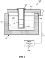
FIG. 1 , a structural configuration of a sonic mixing apparatus 100 (hereinafter "mixing apparatus") in accordance with one or more embodiments of the present invention is shown. Themixing apparatus 100 includes acontainer 102 including areservoir 104 formed of container walls (e.g., inner and outer container walls and a floor) that is configured to receive and contain acoupling liquid 106. In one or more embodiment, thereservoir 104 may have an annular shape and may have an annular recess formed therein that may include an open top.Coupling liquid 106 may be any suitable liquid that functions to aid in the transmission of vibrations (e.g., pressure waves) to thereaction vessel 107 which is suspended in thecoupling liquid 106 contained within thereservoir 104.Coupling liquid 106 may be a liquid such as water, but may also be a gel (e.g., an ultrasound gel). -
Mixing apparatus 100 further includes atransducer 108. Thetransducer 108 is configured to be driven at high frequency to produce a wave or other disturbance that communicates with thecoupling liquid 106. Thetransducer 108 may be drive at approximately a resonant frequency of thetransducer 108 in some embodiment. "Communicate" as used herein means causing or producing pressure waves in thecoupling liquid 106. In one or more embodiments, thetransducer 108 may be immersed in thecoupling liquid 106 and may include one or more surfaces that act directly upon thecoupling liquid 106. In some embodiments, thetransducer 108 may be coupled to a container side wall of thereservoir 104 of thecontainer 102.Transducer 108 may be a piezoelectric transducer in some embodiments. For example, a lead, zirconate and titanate piezoelectric (PZT) ceramic material may be used for thetransducer 108. One or more piezoelectric material (e.g., crystal elements) may be used. Thetransducer 108 may have an effective driving area of any suitable shape (e.g., circular, rectangular, square, or the like) that is large enough to set up standing waves in the entire volume of the component to be mixed that is held by thereaction vessel 107. Effective driving area may be between about 50 mm2 and about 1000 mm2, or about 175 mm2 for a 7 mm 7 mm x 7 mm x 15 mm volume of components to be mixed in some embodiments. Other types and driving areas of suitable high-frequency transducers may be used.Transducer 108 may, in one or more embodiments, be driven at a substantially constant frequency. The drive frequency (ω) may be dependent on the number of standing waves that are desired to be generated in thereaction vessel 107. Thetransducer 108 is driven at between about 200 KHz and about 4 MHz. In one example, 16 vertically-oriented standing waves may be generated in a reaction vessel having a 7 mm width, when drive at about 1.72 MHz. - In more detail, mixing
apparatus 100 further includes asignal generation unit 110 that is configured to produce a phase modulatable drive signal to thetransducer 108 inline 111.Signal generation unit 110 may be configured to be driven at approximately a resonant frequency of thetransducer 108.Signal generation unit 110 is operational to produce a drive signal inline 111 to drive thetransducer 108 that is phase modulatable. The term "phase modulatable" as used herein means that the drive signal may be actively varied in phase. Thesignal generation unit 110 is be configured to modulate the phase of the phase modulatable drive signal between a first phase angle and a second phase angle, over time, wherein the second phase angle is different than the first phase angle.Signal generation unit 110 may be configured to adjust the phase of the phase modulatable drive signal between about 0 degrees and about 180 degrees in some embodiments. Large variations in phase over time were discovered by the inventors to provide rapid mixing of components, given that the standings waves move back and forth in direct correlation to the magnitude of any phase change. For example, a phase angle change of 180 degrees may cause the standing wave to move back and forth by one half of the wavelength of the wave causing the standing wave. Producing the moving standing waves promotes some mixing of the first and second components (e.g.,patient sample 109 and reagent 112). Variation between other phase angles, other than 0 and 180, may be used. - As shown in
FIG. 1 and2 , thereaction vessels 107 is received in acarrier member 114. For example, thereaction vessels 107 may be received in apertures formed therein.Carrier member 114 may be contain a number ofreaction vessels 107, which may be identical and may be arranged in a circle, such as shown inFIG. 2 .Carrier member 114 may be rotated by adrive member 115, which may be engaged with thecarrier member 114 in some manner. For example,drive member 115 may be a gear that engages withgear teeth 117 formed on the radial inside surface of thecarrier member 114. Other suitable known drive mechanisms may be used to rotate thecarrier member 114. Rotation of thecarrier member 114 may be by operation of a drive motor 116 coupled to and driving thedrive member 115, such as by a motor shaft. Thecarrier member 114 andcontainer 102 forming thereservoir 104 may be included within aclinical analyzer apparatus 200 as is shown inFIG. 2 . -
Clinical analyzer apparatus 200, as best shown inFIG. 2 , may include ahousing 218 that may include a frame or other support structures therein. Thecontainer 102 and the drive motor 116 may be supported relative to thehousing 218. Theclinical analyzer apparatus 200 may receive one or more sample racks 220 (multiple racks shown) containingsample containers 222 havingpatient samples 109 therein.Sample racks 220 may be received on a tray, for example.Patient samples 109 may be urine, whole blood, blood serum or plasma, swab extracts from urogenital, nasopharyngeal, buccal or eye swabs, cerebral spinal fluid, semen, stool, breast milk, saliva, sputum, cell culture, amniotic fluid, ascites, bronchial alveoli lavage (BAL), collection media, peripheral blood mononuclear cells (PBMC), buffy coat, or the like. - A robot and coupled pipette (collectively designated by first arrow 224) and aspiration/dispense system (not shown) may aspirate
patient sample 109 from thesample containers 222 in thesample rack 220 and move the pipette to dispense thepatient sample 109 into thereaction vessel 107 that is being carried by thecarrier member 114. One by one,patient samples 109 may be dispensed tosuccessive reaction vessels 107 that have been rotated to the patient sample dispense location in line withfirst arrow 224. A new pipette tip may be obtained by the pipette from atip supply 225 for each new dispense of a differentpatient sample 109. Any suitable aspiration/dispensing system may be used for the aspiration and dispensing ofpatient samples 109 and various consumables, such as described inUS 5,777,221 ;US 6,060,320 ;US 6,158,269 ;US 6,250,130 ;US 6,463,969 :US 7,998,751 ;US 7,205,158 . Other suitable aspiration/dispensing systems may be used. - Once the
patient sample 109 is dispensed to thereaction vessel 107, thecarrier member 114 may be rotated to a reagent addition location and one ormore reagents 112 may be added from areagent supply 226 by a second robot and pipette (collectively designed by second arrow 228). At the location of the reagent addition, the transducer 108 (shown dotted and enlarged inFIG. 2 ) may be located. Thetransducer 108 may be driven by the drive signal inline 111 from thesignal generation unit 110, which may be part of a controller 230 for theclinical analyzer apparatus 200. Controller 230 may be responsible for coordinating the other movements of the various robots, motions of thecarrier member 114, and other functions of theclinical analyzer apparatus 200. Controller 230 may include microprocessor and memory suitable for storing programming and for carrying out instructions. In some embodiments, there may be an additional reagent addition from asecond reagent supply 229. Another transducer may be added at that location to mix the added reagent from thesecond reagent supply 229 with the components (e.g.,patient sample 109 and one or more reagents 112) previously mixed by operation of thetransducer 108. - Driving the
transducer 108 may operate to produce vibrations in thecoupling liquid 106 that set up standing waves within thereaction vessel 107, as is shown inFIG. 4B. FIG. 4A illustrates thepatient sample 109 being drawn up into thereagent 112 as thetransducer 108 is vibrated at the operating frequency (ω), with phase being held constant. Obviously, some mixing may have already occurred as thereagent 112 is added by the second robot and pipette (designated by second arrow 228), so the patterns shown are only illustrative of the standing waves as they are being formed. The drive signal inline 111, which may be a voltage signal v(t) from thesignal generation unit 110, may take the form ofEquation 1 below in some embodiments:
- A is the amplitude of the drive signal (Volts),
- Ω is the drive signal frequency (in Hz),
- T is the time (in seconds), and
- Θ is the phase angle (in degrees).
- Initially, the drive signal in 111 may be a pure sinusoidal signal and the phase angle Θ may be zero, so that the drive signal V(t) signal takes the form of
equation 2 below:
- As the standing
waves 432 become fully formed as shown inFIG. 4B (e.g., illustrating vertically-oriented standing waves), then the drive signal V (t) inline 111 may be phase modulated. Phase modulating the drive signal inline 111 operates to move the standing waves back and forth in the direction shown by mixingdirectional arrow 444 approximately in proportion to the amount of phase change (Δ phase angle) that has been imparted to the drive signal inline 111. The phase angle is changed by a Δ phase angle of from about 0 degrees to about 180 degrees. However, the phase modulation may not need to wait until the standingwaves 432 are fully developed, and may start when they are undeveloped or only partially developed in some embodiments. - As shown in
FIG. 3A , thesignal generator unit 110 includes anoscillator 346. Theoscillator 346 may generate asinusoidal wave 347, as is shown inFIG. 3B . Thesinusoidal wave 347 has a frequency as discussed above, for example. Theoscillator 346 may be a harmonic or linear type oscillator (examples of are a Colpitts oscillator, Hartley, Armstrong oscillator (also known as a Meissner oscillator), Clapp oscillator, and a Wien bridge oscillator. Theoscillator 346 may be adjustable in amplitude A, in some embodiments. -
Signal generator unit 110 includes aphase modulator circuit 348 that receives thesinusoidal wave 347 at the desired frequency (ω) and adjusts the phase angle Θ thereof, such as according toEquation 1. This results in a phase shifted signal 351 (shown dotted inFIG. 3B ). In one or more embodiments, thephase modulator circuit 348 may rapidly change the phase angle θ, e.g., impulsively. The phase angle is modulated between a first phase angle and a second phase angle at a modulation frequency. Modulation frequency is between about 1 Hz and about 50 Hz. In one or more embodiments, the signal output inoutput line 349 may be filtered by afilter 350.Filter 350 may be a suitable low pass filter. For example, the cutoff frequency of thefilter 350 may be set greater than or equal to the desired drive frequency (ω) of theoscillator 346. Depending upon the strength of the signal exiting thephase modulator circuit 348, the signal inoutput line 349 may need amplified by anamplifier 352. Any suitable amplifier may be used, such as a class A, B or D class amplifier. The amplified signal is the drive signal inline 111 that drives thetransducer 108 to cause standing waves to be generated within thereaction vessel 107. -
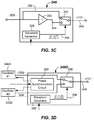
FIG. 3C illustrates a first embodiment of aphase modulator circuit 348. In the depicted embodiment, a combination of anoperational amplifier 353 and ananalog multiplexor 355 may be used to provide a phase modulated drive signal. Theoperational amplifier 353 may operate as an inverter, multiplying the input signal by - 1, and thus phase shifting the signal by 180 degrees insecond line 354. Theanalog multiplexor 355 may be used to modulate between a first signal (e.g., a sine wave) received directly from the oscillator 346 (FIG. 3A ) infirst line 356, and a second phase shifted signal in asecond line 354. Theanalog multiplexor 355 may be switched by any suitable means. For example, theanalog multiplexor 355 may be switched in time in accordance with amodulation signal 358 from awaveform generator 359. Thewaveform generator 359 may be a 555 timer configured in an Astable mode, for example. Switching between the first andsecond lines waveform generator 359. The modulation frequency of the waveform generator may be selected, set or provided as described above. Other suitable variants may be used. - In another embodiment, as is shown in
FIG. 3D , aphase modulator circuit 348D that receives inputs frommultiple oscillators Oscillator # 1 346A may generate a first wave (e.g., a sine wave), whereasoscillator # 2 346B may generate a second wave that is out of phase with the first wave (as shown inFIG. 3B ). In some embodiments, the second wave is 180 degrees out of phase with the first wave. Other phase differences are possible. Aphase synchronization circuit 360 may be included to set and/or maintain a desired phase difference.Phase synchronization circuit 360 may be a phase-locked loop in some embodiments. As before, a switching component, such as ananalog multiplexor 355 may be used to switch between the inputs fromoscillator # 1 andoscillator # 2. Similarly, the rate of switching may be controlled by a modulation signal from thewaveform generator 359. By switching between the inputs fromoscillator # 1 andoscillator # 2, the signal inoutput line 349 may be phase modulated. - In other embodiments, the a
signal generation unit 310 that is configured to provide a phase modulatable drive signal to thetransducer 108 to produce moving standing waves 432 (FIG. 4B ) may be implemented entirely digitally. For example, as shown inFIG. 3E , thesignal generation unit 310 may include a digital signal processor (DSP) 365 that communicates with a directdigital synthesizer 370. Communication may be by any suitable communication protocol, such as SPI, I2c, or the like. TheDSP 365 may provide the operating frequency ω and the modulating frequency to the directdigital synthesizer 370. An AD9833 chip from Analog Devices may be used, for example. A programmable waveform generator may be used in place of the directdigital synthesizer 370 in some embodiments. Other suitable all-digital implementations of the signal generation unit may be used. -
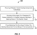
FIG. 5 illustrates a method of mixing components (e.g.,patient sample 109 and reagent 112), such as in a reaction vessel (e.g., reaction vessel 107) in a clinical analyzer apparatus (e.g., clinical analyzer apparatus 200). Themethod 500 includes providing a reaction vessel (e.g., reaction vessel 107) including components to be mixed (e.g.,patient sample 109 and reagent 112) in 502. - The
method 500 further includes, in 504, providing a drive signal (e.g., in line 111) to a transducer (e.g., transducer 108) to produce vibrations at a desired frequency (e.g., at frequency ω) resulting in standing waves (e.g., standing waves 432) in the reaction vessel. - The
method 500 includes, in 506, phase modulating the drive signal to move the standing waves and promote mixing of the components. Phase modulation may be accomplished using one or more oscillators (e.g.,oscillator phase modulator circuit - Although the invention is illustrated and described herein with reference to specific embodiments, the invention is not intended to be limited to the details shown.
Claims (8)
- A sonic mixing apparatus (100), comprising:a reservoir (104) configured to contain a coupling liquid (106);a reaction vessel (107) suspended in the reservoir (104) from a carrier member (114);a transducer (108) configured to be driven at a frequency and communicate with the coupling liquid (106); anda signal generation unit (110) configured to provide a phase modulatable drive signal to the transducer (108) wherein the signal generation unit (110) includes an oscillator (346) operable at between about 200 KHz and about 4MHz; and wherein the signal generation unit (110) comprises a phase modulator circuit (348) including a wave generator configured to produce a modulation signal which is configured to modulate a phase of the phase modulatable drive signal between a first phase angle and a second phase angle which is different than the first phase angle wherein the modulation between the first phase angle and the second phase angle cycling takes place at a modulation frequency of between about 1 Hz and about 50 Hz.
- The sonic mixing apparatus of claim 1, wherein the reservoir (104) comprises an annular recess.
- The sonic mixing apparatus of claim 1, wherein the signal generation unit (110) either- is configured to be driven at approximately a resonant frequency of the transducer (108); or- is configured to adjust a phase of the phase modulatable drive signal between about 0 degrees and about 180 degrees; or- comprises an analog multiplexor (355); or- comprises a low pass filter.
- The sonic mixing apparatus of claim 1, wherein components to be mixed are patient sample (109) and reagent (112).
- An analyzer apparatus (200) including the sonic mixing apparatus of claim 1.
- A method of mixing components, comprising:providing a reaction vessel (107) including the components to be mixed;suspending the reaction vessel (107) from a carrier member (114) in a reservoir (104) containing a coupling liquid (106);providing a drive signal of about 200 KHz and about 4MHz to a transducer (108) to produce vibrations at a desired frequency resulting in standing waves (432) in the reaction vessel (107); andphase modulating the drive signal to move the standing waves (432) and promote mixing of the components, wherein the phase modulating includes modulating between a first phase angle and a second phase angle andwherein the modulation between the first phase angle and the second phase angle cycling takes place at a modulation frequency of between about 1 Hz and about 50 Hz.
- The method of claim 6, wherein the components to be mixed are patient sample (109) and reagent (112).
- The use of a sonic mixing apparatus of claim 1 in an analyzer apparatus.
Applications Claiming Priority (2)
| Application Number | Priority Date | Filing Date | Title |
|---|---|---|---|
| US201462056194P | 2014-09-26 | 2014-09-26 | |
| PCT/US2015/050492 WO2016048760A1 (en) | 2014-09-26 | 2015-09-16 | Phase-modulated standing wave mixing apparatus and methods |
Publications (3)
| Publication Number | Publication Date |
|---|---|
| EP3198258A1 EP3198258A1 (en) | 2017-08-02 |
| EP3198258A4 EP3198258A4 (en) | 2017-11-01 |
| EP3198258B1 true EP3198258B1 (en) | 2021-05-19 |
Family
ID=55581826
Family Applications (1)
| Application Number | Title | Priority Date | Filing Date |
|---|---|---|---|
| EP15844882.9A Active EP3198258B1 (en) | 2014-09-26 | 2015-09-16 | Phase-modulated standing wave mixing apparatus and method |
Country Status (6)
| Country | Link |
|---|---|
| US (1) | US10737228B2 (en) |
| EP (1) | EP3198258B1 (en) |
| JP (1) | JP6805134B2 (en) |
| CN (1) | CN106687797B (en) |
| CA (1) | CA2962594C (en) |
| WO (1) | WO2016048760A1 (en) |
Families Citing this family (8)
| Publication number | Priority date | Publication date | Assignee | Title |
|---|---|---|---|---|
| FR3050211B1 (en) * | 2016-04-19 | 2018-04-13 | Etablissement Français Du Sang | DEVICE FOR SEGMENTING DNA SAMPLES |
| TWI766942B (en) | 2017-02-13 | 2022-06-11 | 美商海科生醫有限責任公司 | Apparatuses and methods for mixing fluid or media by vibrating a pipette using transient and steady-state intervals |
| WO2019000902A1 (en) | 2017-06-28 | 2019-01-03 | 中国科学院宁波工业技术研究院慈溪生物医学工程研究所 | Detection analyzer |
| CN109142657B (en) * | 2017-06-28 | 2020-08-07 | 中国科学院宁波工业技术研究院慈溪生物医学工程研究所 | A detection analyzer |
| JP6858096B2 (en) * | 2017-08-23 | 2021-04-14 | 株式会社日立ハイテク | Chemical analyzer |
| DE102018212125A1 (en) * | 2018-07-20 | 2020-01-23 | Robert Bosch Gmbh | Microfluidic system and method for mixing fluids |
| CN112774533A (en) * | 2020-12-18 | 2021-05-11 | 昆山微电子技术研究院 | Solid-liquid dispersion device |
| WO2025264457A1 (en) * | 2024-06-19 | 2025-12-26 | Siemens Healthcare Diagnostics Inc. | Mixing using frequency-modulated standing waves |
Family Cites Families (18)
| Publication number | Priority date | Publication date | Assignee | Title |
|---|---|---|---|---|
| US2650872A (en) * | 1947-10-30 | 1953-09-01 | Lever Brothers Ltd | Method and apparatus utilizing compressional wave energy in the upper sonic and supersonic range for washing textiles |
| US4930532A (en) * | 1989-02-17 | 1990-06-05 | Ipco Corporation | Beaker holder for use with ultrasonic cleaning device |
| US5736100A (en) * | 1994-09-20 | 1998-04-07 | Hitachi, Ltd. | Chemical analyzer non-invasive stirrer |
| US7687039B2 (en) * | 1998-10-28 | 2010-03-30 | Covaris, Inc. | Methods and systems for modulating acoustic energy delivery |
| US6948843B2 (en) * | 1998-10-28 | 2005-09-27 | Covaris, Inc. | Method and apparatus for acoustically controlling liquid solutions in microfluidic devices |
| EP1178601B1 (en) * | 2000-08-04 | 2005-02-16 | Freescale Semiconductor, Inc. | Frequency modulation using a digital filter for baseband waveshaping |
| US6626253B2 (en) | 2001-02-27 | 2003-09-30 | Baker Hughes Incorporated | Oscillating shear valve for mud pulse telemetry |
| DE10117772C2 (en) | 2001-04-09 | 2003-04-03 | Advalytix Ag | Mixing device and mixing method for mixing small amounts of liquid |
| JP3746239B2 (en) | 2002-02-28 | 2006-02-15 | 株式会社日立ハイテクノロジーズ | Automatic analyzer |
| WO2005025730A1 (en) | 2003-09-10 | 2005-03-24 | Burr Ronald F | Acoustic fluidized bed |
| GB2425974A (en) | 2005-05-09 | 2006-11-15 | Orion Diagnostica Oy | Sonication of a medium |
| JP2007078618A (en) | 2005-09-16 | 2007-03-29 | Nippon Support System Kk | Ultrasonic generator for stirring and deairing micro-plate or the like with ultrasonic wave |
| US20070267351A1 (en) * | 2006-05-22 | 2007-11-22 | Traceguard Technologies Inc. | Low-frequency acoustic waves for collecting and/or moving particles inside articles |
| JP2008256565A (en) | 2007-04-05 | 2008-10-23 | Olympus Corp | Stirring apparatus and analyzer |
| JP5159197B2 (en) | 2007-07-25 | 2013-03-06 | キヤノン株式会社 | Liquid control device |
| US20090052272A1 (en) * | 2007-08-20 | 2009-02-26 | Artann Laboratories, Inc. | Ultrasonic stirring of liquids in small volumes |
| JP2009270941A (en) | 2008-05-08 | 2009-11-19 | Hitachi High-Technologies Corp | Automatic analysis apparatus |
| ITUD20080126A1 (en) | 2008-05-27 | 2009-11-28 | Alifax International S A | MIXING DEVICE AND ITS MIXING PROCEDURE |
-
2015
- 2015-09-16 EP EP15844882.9A patent/EP3198258B1/en active Active
- 2015-09-16 CA CA2962594A patent/CA2962594C/en active Active
- 2015-09-16 US US15/511,578 patent/US10737228B2/en active Active
- 2015-09-16 CN CN201580051689.3A patent/CN106687797B/en active Active
- 2015-09-16 JP JP2017516352A patent/JP6805134B2/en active Active
- 2015-09-16 WO PCT/US2015/050492 patent/WO2016048760A1/en not_active Ceased
Non-Patent Citations (1)
| Title |
|---|
| None * |
Also Published As
| Publication number | Publication date |
|---|---|
| CN106687797B (en) | 2020-11-10 |
| US10737228B2 (en) | 2020-08-11 |
| EP3198258A1 (en) | 2017-08-02 |
| US20170246601A1 (en) | 2017-08-31 |
| WO2016048760A1 (en) | 2016-03-31 |
| CN106687797A (en) | 2017-05-17 |
| CA2962594A1 (en) | 2016-03-31 |
| JP6805134B2 (en) | 2020-12-23 |
| CA2962594C (en) | 2021-02-02 |
| EP3198258A4 (en) | 2017-11-01 |
| JP2017529540A (en) | 2017-10-05 |
Similar Documents
| Publication | Publication Date | Title |
|---|---|---|
| EP3198258B1 (en) | Phase-modulated standing wave mixing apparatus and method | |
| US20090227042A1 (en) | Coustic Concentration Method and Device and a Reaction Method | |
| US4046515A (en) | Diluting and agitating device | |
| US3780992A (en) | Vibrating pipette probe mixer | |
| CN112041685A (en) | Chemical analysis device | |
| JP2009270941A (en) | Automatic analysis apparatus | |
| CN112538426B (en) | Acoustic wave driven bubble resonance and micro-flow field excitation device and method | |
| Iida et al. | Bubble motions confined in a microspace observed with stroboscopic technique | |
| EP3560611B1 (en) | Ultrasonic washer and automatic analysis apparatus using same | |
| JP2006349380A (en) | Stirrer, stirring method, reaction container and analyzer equipped with stirrer | |
| JP4085230B2 (en) | Stirring device and analyzer equipped with the stirring device | |
| CN110691975B (en) | Automatic analysis device and analysis method | |
| EP0209872A2 (en) | Method and apparatus for ultrasonic interface detection | |
| JP5668021B2 (en) | Automatic analyzer | |
| JP5919364B2 (en) | Automatic analyzer | |
| JP6858096B2 (en) | Chemical analyzer | |
| CN207439793U (en) | A kind of suspended matter mechanical mixing apparatus and the mixer using the device | |
| WO2025264457A1 (en) | Mixing using frequency-modulated standing waves | |
| JP3595883B2 (en) | Fluid drive device, chemical analyzer and fluid drive method | |
| JP2011141244A (en) | Analyzer | |
| EP0212280A2 (en) | Self-cleaning ultrasonic horn | |
| JP2004333348A (en) | Processing device | |
| JP2022126439A (en) | Autoanalyzer | |
| JP2007040847A (en) | Stirrer and analyzer equipped with stirrer | |
| JP2006242806A (en) | Dispensing apparatus |
Legal Events
| Date | Code | Title | Description |
|---|---|---|---|
| STAA | Information on the status of an ep patent application or granted ep patent |
Free format text: STATUS: THE INTERNATIONAL PUBLICATION HAS BEEN MADE |
|
| PUAI | Public reference made under article 153(3) epc to a published international application that has entered the european phase |
Free format text: ORIGINAL CODE: 0009012 |
|
| STAA | Information on the status of an ep patent application or granted ep patent |
Free format text: STATUS: REQUEST FOR EXAMINATION WAS MADE |
|
| 17P | Request for examination filed |
Effective date: 20170425 |
|
| AK | Designated contracting states |
Kind code of ref document: A1 Designated state(s): AL AT BE BG CH CY CZ DE DK EE ES FI FR GB GR HR HU IE IS IT LI LT LU LV MC MK MT NL NO PL PT RO RS SE SI SK SM TR |
|
| AX | Request for extension of the european patent |
Extension state: BA ME |
|
| A4 | Supplementary search report drawn up and despatched |
Effective date: 20171002 |
|
| RIC1 | Information provided on ipc code assigned before grant |
Ipc: G01N 35/00 20060101ALN20170926BHEP Ipc: G01N 35/10 20060101ALN20170926BHEP Ipc: G01N 35/02 20060101ALN20170926BHEP Ipc: B01F 11/02 20060101AFI20170926BHEP |
|
| DAV | Request for validation of the european patent (deleted) | ||
| DAX | Request for extension of the european patent (deleted) | ||
| REG | Reference to a national code |
Ref country code: DE Ref legal event code: R079 Ref document number: 602015069544 Country of ref document: DE Free format text: PREVIOUS MAIN CLASS: G01N0015140000 Ipc: B01F0011020000 |
|
| GRAP | Despatch of communication of intention to grant a patent |
Free format text: ORIGINAL CODE: EPIDOSNIGR1 |
|
| STAA | Information on the status of an ep patent application or granted ep patent |
Free format text: STATUS: GRANT OF PATENT IS INTENDED |
|
| RIC1 | Information provided on ipc code assigned before grant |
Ipc: G01N 35/00 20060101ALN20201112BHEP Ipc: G01N 35/02 20060101ALN20201112BHEP Ipc: G01N 35/10 20060101ALN20201112BHEP Ipc: B01F 11/02 20060101AFI20201112BHEP |
|
| INTG | Intention to grant announced |
Effective date: 20201201 |
|
| GRAS | Grant fee paid |
Free format text: ORIGINAL CODE: EPIDOSNIGR3 |
|
| GRAA | (expected) grant |
Free format text: ORIGINAL CODE: 0009210 |
|
| STAA | Information on the status of an ep patent application or granted ep patent |
Free format text: STATUS: THE PATENT HAS BEEN GRANTED |
|
| AK | Designated contracting states |
Kind code of ref document: B1 Designated state(s): AL AT BE BG CH CY CZ DE DK EE ES FI FR GB GR HR HU IE IS IT LI LT LU LV MC MK MT NL NO PL PT RO RS SE SI SK SM TR |
|
| REG | Reference to a national code |
Ref country code: GB Ref legal event code: FG4D |
|
| REG | Reference to a national code |
Ref country code: CH Ref legal event code: EP |
|
| REG | Reference to a national code |
Ref country code: DE Ref legal event code: R096 Ref document number: 602015069544 Country of ref document: DE |
|
| REG | Reference to a national code |
Ref country code: AT Ref legal event code: REF Ref document number: 1393454 Country of ref document: AT Kind code of ref document: T Effective date: 20210615 |
|
| REG | Reference to a national code |
Ref country code: IE Ref legal event code: FG4D |
|
| REG | Reference to a national code |
Ref country code: LT Ref legal event code: MG9D |
|
| REG | Reference to a national code |
Ref country code: AT Ref legal event code: MK05 Ref document number: 1393454 Country of ref document: AT Kind code of ref document: T Effective date: 20210519 |
|
| REG | Reference to a national code |
Ref country code: NL Ref legal event code: MP Effective date: 20210519 |
|
| PG25 | Lapsed in a contracting state [announced via postgrant information from national office to epo] |
Ref country code: HR Free format text: LAPSE BECAUSE OF FAILURE TO SUBMIT A TRANSLATION OF THE DESCRIPTION OR TO PAY THE FEE WITHIN THE PRESCRIBED TIME-LIMIT Effective date: 20210519 Ref country code: AT Free format text: LAPSE BECAUSE OF FAILURE TO SUBMIT A TRANSLATION OF THE DESCRIPTION OR TO PAY THE FEE WITHIN THE PRESCRIBED TIME-LIMIT Effective date: 20210519 Ref country code: BG Free format text: LAPSE BECAUSE OF FAILURE TO SUBMIT A TRANSLATION OF THE DESCRIPTION OR TO PAY THE FEE WITHIN THE PRESCRIBED TIME-LIMIT Effective date: 20210819 Ref country code: LT Free format text: LAPSE BECAUSE OF FAILURE TO SUBMIT A TRANSLATION OF THE DESCRIPTION OR TO PAY THE FEE WITHIN THE PRESCRIBED TIME-LIMIT Effective date: 20210519 Ref country code: FI Free format text: LAPSE BECAUSE OF FAILURE TO SUBMIT A TRANSLATION OF THE DESCRIPTION OR TO PAY THE FEE WITHIN THE PRESCRIBED TIME-LIMIT Effective date: 20210519 |
|
| REG | Reference to a national code |
Ref country code: DE Ref legal event code: R079 Ref document number: 602015069544 Country of ref document: DE Free format text: PREVIOUS MAIN CLASS: B01F0011020000 Ipc: B01F0031800000 |
|
| PG25 | Lapsed in a contracting state [announced via postgrant information from national office to epo] |
Ref country code: RS Free format text: LAPSE BECAUSE OF FAILURE TO SUBMIT A TRANSLATION OF THE DESCRIPTION OR TO PAY THE FEE WITHIN THE PRESCRIBED TIME-LIMIT Effective date: 20210519 Ref country code: SE Free format text: LAPSE BECAUSE OF FAILURE TO SUBMIT A TRANSLATION OF THE DESCRIPTION OR TO PAY THE FEE WITHIN THE PRESCRIBED TIME-LIMIT Effective date: 20210519 Ref country code: NO Free format text: LAPSE BECAUSE OF FAILURE TO SUBMIT A TRANSLATION OF THE DESCRIPTION OR TO PAY THE FEE WITHIN THE PRESCRIBED TIME-LIMIT Effective date: 20210819 Ref country code: PL Free format text: LAPSE BECAUSE OF FAILURE TO SUBMIT A TRANSLATION OF THE DESCRIPTION OR TO PAY THE FEE WITHIN THE PRESCRIBED TIME-LIMIT Effective date: 20210519 Ref country code: PT Free format text: LAPSE BECAUSE OF FAILURE TO SUBMIT A TRANSLATION OF THE DESCRIPTION OR TO PAY THE FEE WITHIN THE PRESCRIBED TIME-LIMIT Effective date: 20210920 Ref country code: IS Free format text: LAPSE BECAUSE OF FAILURE TO SUBMIT A TRANSLATION OF THE DESCRIPTION OR TO PAY THE FEE WITHIN THE PRESCRIBED TIME-LIMIT Effective date: 20210919 Ref country code: LV Free format text: LAPSE BECAUSE OF FAILURE TO SUBMIT A TRANSLATION OF THE DESCRIPTION OR TO PAY THE FEE WITHIN THE PRESCRIBED TIME-LIMIT Effective date: 20210519 Ref country code: GR Free format text: LAPSE BECAUSE OF FAILURE TO SUBMIT A TRANSLATION OF THE DESCRIPTION OR TO PAY THE FEE WITHIN THE PRESCRIBED TIME-LIMIT Effective date: 20210820 |
|
| PG25 | Lapsed in a contracting state [announced via postgrant information from national office to epo] |
Ref country code: NL Free format text: LAPSE BECAUSE OF FAILURE TO SUBMIT A TRANSLATION OF THE DESCRIPTION OR TO PAY THE FEE WITHIN THE PRESCRIBED TIME-LIMIT Effective date: 20210519 |
|
| PG25 | Lapsed in a contracting state [announced via postgrant information from national office to epo] |
Ref country code: DK Free format text: LAPSE BECAUSE OF FAILURE TO SUBMIT A TRANSLATION OF THE DESCRIPTION OR TO PAY THE FEE WITHIN THE PRESCRIBED TIME-LIMIT Effective date: 20210519 Ref country code: CZ Free format text: LAPSE BECAUSE OF FAILURE TO SUBMIT A TRANSLATION OF THE DESCRIPTION OR TO PAY THE FEE WITHIN THE PRESCRIBED TIME-LIMIT Effective date: 20210519 Ref country code: EE Free format text: LAPSE BECAUSE OF FAILURE TO SUBMIT A TRANSLATION OF THE DESCRIPTION OR TO PAY THE FEE WITHIN THE PRESCRIBED TIME-LIMIT Effective date: 20210519 Ref country code: SM Free format text: LAPSE BECAUSE OF FAILURE TO SUBMIT A TRANSLATION OF THE DESCRIPTION OR TO PAY THE FEE WITHIN THE PRESCRIBED TIME-LIMIT Effective date: 20210519 Ref country code: SK Free format text: LAPSE BECAUSE OF FAILURE TO SUBMIT A TRANSLATION OF THE DESCRIPTION OR TO PAY THE FEE WITHIN THE PRESCRIBED TIME-LIMIT Effective date: 20210519 Ref country code: RO Free format text: LAPSE BECAUSE OF FAILURE TO SUBMIT A TRANSLATION OF THE DESCRIPTION OR TO PAY THE FEE WITHIN THE PRESCRIBED TIME-LIMIT Effective date: 20210519 Ref country code: ES Free format text: LAPSE BECAUSE OF FAILURE TO SUBMIT A TRANSLATION OF THE DESCRIPTION OR TO PAY THE FEE WITHIN THE PRESCRIBED TIME-LIMIT Effective date: 20210519 |
|
| REG | Reference to a national code |
Ref country code: DE Ref legal event code: R097 Ref document number: 602015069544 Country of ref document: DE |
|
| PLBE | No opposition filed within time limit |
Free format text: ORIGINAL CODE: 0009261 |
|
| STAA | Information on the status of an ep patent application or granted ep patent |
Free format text: STATUS: NO OPPOSITION FILED WITHIN TIME LIMIT |
|
| 26N | No opposition filed |
Effective date: 20220222 |
|
| REG | Reference to a national code |
Ref country code: CH Ref legal event code: PL |
|
| REG | Reference to a national code |
Ref country code: BE Ref legal event code: MM Effective date: 20210930 |
|
| PG25 | Lapsed in a contracting state [announced via postgrant information from national office to epo] |
Ref country code: IS Free format text: LAPSE BECAUSE OF FAILURE TO SUBMIT A TRANSLATION OF THE DESCRIPTION OR TO PAY THE FEE WITHIN THE PRESCRIBED TIME-LIMIT Effective date: 20210919 Ref country code: MC Free format text: LAPSE BECAUSE OF FAILURE TO SUBMIT A TRANSLATION OF THE DESCRIPTION OR TO PAY THE FEE WITHIN THE PRESCRIBED TIME-LIMIT Effective date: 20210519 Ref country code: AL Free format text: LAPSE BECAUSE OF FAILURE TO SUBMIT A TRANSLATION OF THE DESCRIPTION OR TO PAY THE FEE WITHIN THE PRESCRIBED TIME-LIMIT Effective date: 20210519 |
|
| PG25 | Lapsed in a contracting state [announced via postgrant information from national office to epo] |
Ref country code: LU Free format text: LAPSE BECAUSE OF NON-PAYMENT OF DUE FEES Effective date: 20210916 Ref country code: IT Free format text: LAPSE BECAUSE OF FAILURE TO SUBMIT A TRANSLATION OF THE DESCRIPTION OR TO PAY THE FEE WITHIN THE PRESCRIBED TIME-LIMIT Effective date: 20210519 Ref country code: IE Free format text: LAPSE BECAUSE OF NON-PAYMENT OF DUE FEES Effective date: 20210916 Ref country code: BE Free format text: LAPSE BECAUSE OF NON-PAYMENT OF DUE FEES Effective date: 20210930 |
|
| PG25 | Lapsed in a contracting state [announced via postgrant information from national office to epo] |
Ref country code: LI Free format text: LAPSE BECAUSE OF NON-PAYMENT OF DUE FEES Effective date: 20210930 Ref country code: CH Free format text: LAPSE BECAUSE OF NON-PAYMENT OF DUE FEES Effective date: 20210930 |
|
| PG25 | Lapsed in a contracting state [announced via postgrant information from national office to epo] |
Ref country code: HU Free format text: LAPSE BECAUSE OF FAILURE TO SUBMIT A TRANSLATION OF THE DESCRIPTION OR TO PAY THE FEE WITHIN THE PRESCRIBED TIME-LIMIT; INVALID AB INITIO Effective date: 20150916 |
|
| PG25 | Lapsed in a contracting state [announced via postgrant information from national office to epo] |
Ref country code: CY Free format text: LAPSE BECAUSE OF FAILURE TO SUBMIT A TRANSLATION OF THE DESCRIPTION OR TO PAY THE FEE WITHIN THE PRESCRIBED TIME-LIMIT Effective date: 20210519 |
|
| PG25 | Lapsed in a contracting state [announced via postgrant information from national office to epo] |
Ref country code: MK Free format text: LAPSE BECAUSE OF FAILURE TO SUBMIT A TRANSLATION OF THE DESCRIPTION OR TO PAY THE FEE WITHIN THE PRESCRIBED TIME-LIMIT Effective date: 20210519 |
|
| PG25 | Lapsed in a contracting state [announced via postgrant information from national office to epo] |
Ref country code: TR Free format text: LAPSE BECAUSE OF FAILURE TO SUBMIT A TRANSLATION OF THE DESCRIPTION OR TO PAY THE FEE WITHIN THE PRESCRIBED TIME-LIMIT Effective date: 20210519 |
|
| PG25 | Lapsed in a contracting state [announced via postgrant information from national office to epo] |
Ref country code: MT Free format text: LAPSE BECAUSE OF FAILURE TO SUBMIT A TRANSLATION OF THE DESCRIPTION OR TO PAY THE FEE WITHIN THE PRESCRIBED TIME-LIMIT Effective date: 20210519 |
|
| REG | Reference to a national code |
Ref country code: DE Ref legal event code: R082 Ref document number: 602015069544 Country of ref document: DE |
|
| PGFP | Annual fee paid to national office [announced via postgrant information from national office to epo] |
Ref country code: FR Payment date: 20250915 Year of fee payment: 11 |
|
| PGFP | Annual fee paid to national office [announced via postgrant information from national office to epo] |
Ref country code: DE Payment date: 20251120 Year of fee payment: 11 |
|
| PGFP | Annual fee paid to national office [announced via postgrant information from national office to epo] |
Ref country code: GB Payment date: 20251002 Year of fee payment: 11 |