EP3197403B1 - Planification chirurgicale - Google Patents
Planification chirurgicale Download PDFInfo
- Publication number
- EP3197403B1 EP3197403B1 EP15784801.1A EP15784801A EP3197403B1 EP 3197403 B1 EP3197403 B1 EP 3197403B1 EP 15784801 A EP15784801 A EP 15784801A EP 3197403 B1 EP3197403 B1 EP 3197403B1
- Authority
- EP
- European Patent Office
- Prior art keywords
- angle
- planned
- cut angle
- values
- selected range
- Prior art date
- Legal status (The legal status is an assumption and is not a legal conclusion. Google has not performed a legal analysis and makes no representation as to the accuracy of the status listed.)
- Active
Links
- 210000002414 leg Anatomy 0.000 claims description 105
- 238000000034 method Methods 0.000 claims description 94
- 210000003127 knee Anatomy 0.000 claims description 57
- 238000001356 surgical procedure Methods 0.000 claims description 46
- 210000000629 knee joint Anatomy 0.000 claims description 16
- 238000012545 processing Methods 0.000 claims description 15
- 238000013150 knee replacement Methods 0.000 claims description 13
- 238000004590 computer program Methods 0.000 claims description 6
- 210000000689 upper leg Anatomy 0.000 description 35
- 238000013459 approach Methods 0.000 description 29
- 239000007943 implant Substances 0.000 description 25
- 238000005520 cutting process Methods 0.000 description 23
- 210000002303 tibia Anatomy 0.000 description 20
- 241000469816 Varus Species 0.000 description 19
- 241001227561 Valgus Species 0.000 description 17
- 210000000988 bone and bone Anatomy 0.000 description 13
- 230000007935 neutral effect Effects 0.000 description 13
- 210000003484 anatomy Anatomy 0.000 description 12
- 238000003860 storage Methods 0.000 description 12
- 210000003423 ankle Anatomy 0.000 description 9
- 238000010586 diagram Methods 0.000 description 8
- 210000004872 soft tissue Anatomy 0.000 description 7
- 238000004364 calculation method Methods 0.000 description 6
- 230000008901 benefit Effects 0.000 description 5
- 230000008569 process Effects 0.000 description 5
- 201000010099 disease Diseases 0.000 description 4
- 208000037265 diseases, disorders, signs and symptoms Diseases 0.000 description 4
- 210000001699 lower leg Anatomy 0.000 description 4
- 230000002980 postoperative effect Effects 0.000 description 4
- 238000004513 sizing Methods 0.000 description 4
- 238000004458 analytical method Methods 0.000 description 3
- 230000008859 change Effects 0.000 description 3
- 230000000694 effects Effects 0.000 description 3
- 210000001624 hip Anatomy 0.000 description 3
- 230000000007 visual effect Effects 0.000 description 3
- 230000006399 behavior Effects 0.000 description 2
- 210000004394 hip joint Anatomy 0.000 description 2
- 239000003550 marker Substances 0.000 description 2
- 238000012986 modification Methods 0.000 description 2
- 230000004048 modification Effects 0.000 description 2
- 230000003287 optical effect Effects 0.000 description 2
- 238000002360 preparation method Methods 0.000 description 2
- 230000003362 replicative effect Effects 0.000 description 2
- 125000006850 spacer group Chemical group 0.000 description 2
- 239000003826 tablet Substances 0.000 description 2
- 238000012546 transfer Methods 0.000 description 2
- 101100008050 Caenorhabditis elegans cut-6 gene Proteins 0.000 description 1
- 208000007366 Genu Valgum Diseases 0.000 description 1
- 206010062061 Knee deformity Diseases 0.000 description 1
- 241000699670 Mus sp. Species 0.000 description 1
- 238000002591 computed tomography Methods 0.000 description 1
- 238000005094 computer simulation Methods 0.000 description 1
- 238000013500 data storage Methods 0.000 description 1
- 230000001419 dependent effect Effects 0.000 description 1
- 238000009826 distribution Methods 0.000 description 1
- 238000005553 drilling Methods 0.000 description 1
- 238000005516 engineering process Methods 0.000 description 1
- 210000002683 foot Anatomy 0.000 description 1
- 210000003041 ligament Anatomy 0.000 description 1
- 210000003141 lower extremity Anatomy 0.000 description 1
- 238000005259 measurement Methods 0.000 description 1
- 230000003278 mimic effect Effects 0.000 description 1
- 230000009467 reduction Effects 0.000 description 1
- 230000010076 replication Effects 0.000 description 1
- 230000000717 retained effect Effects 0.000 description 1
- 238000012552 review Methods 0.000 description 1
- 210000000453 second toe Anatomy 0.000 description 1
- 239000004065 semiconductor Substances 0.000 description 1
- 238000011883 total knee arthroplasty Methods 0.000 description 1
- 230000009466 transformation Effects 0.000 description 1
Images


Classifications
-
- A—HUMAN NECESSITIES
- A61—MEDICAL OR VETERINARY SCIENCE; HYGIENE
- A61B—DIAGNOSIS; SURGERY; IDENTIFICATION
- A61B34/00—Computer-aided surgery; Manipulators or robots specially adapted for use in surgery
- A61B34/10—Computer-aided planning, simulation or modelling of surgical operations
-
- A—HUMAN NECESSITIES
- A61—MEDICAL OR VETERINARY SCIENCE; HYGIENE
- A61B—DIAGNOSIS; SURGERY; IDENTIFICATION
- A61B17/00—Surgical instruments, devices or methods, e.g. tourniquets
- A61B17/14—Surgical saws ; Accessories therefor
- A61B17/15—Guides therefor
- A61B17/154—Guides therefor for preparing bone for knee prosthesis
- A61B17/155—Cutting femur
-
- A—HUMAN NECESSITIES
- A61—MEDICAL OR VETERINARY SCIENCE; HYGIENE
- A61B—DIAGNOSIS; SURGERY; IDENTIFICATION
- A61B17/00—Surgical instruments, devices or methods, e.g. tourniquets
- A61B17/14—Surgical saws ; Accessories therefor
- A61B17/15—Guides therefor
- A61B17/154—Guides therefor for preparing bone for knee prosthesis
- A61B17/157—Cutting tibia
-
- A—HUMAN NECESSITIES
- A61—MEDICAL OR VETERINARY SCIENCE; HYGIENE
- A61B—DIAGNOSIS; SURGERY; IDENTIFICATION
- A61B17/00—Surgical instruments, devices or methods, e.g. tourniquets
- A61B17/56—Surgical instruments or methods for treatment of bones or joints; Devices specially adapted therefor
- A61B2017/564—Methods for bone or joint treatment
-
- A—HUMAN NECESSITIES
- A61—MEDICAL OR VETERINARY SCIENCE; HYGIENE
- A61B—DIAGNOSIS; SURGERY; IDENTIFICATION
- A61B34/00—Computer-aided surgery; Manipulators or robots specially adapted for use in surgery
- A61B34/10—Computer-aided planning, simulation or modelling of surgical operations
- A61B2034/101—Computer-aided simulation of surgical operations
- A61B2034/102—Modelling of surgical devices, implants or prosthesis
- A61B2034/104—Modelling the effect of the tool, e.g. the effect of an implanted prosthesis or for predicting the effect of ablation or burring
-
- A—HUMAN NECESSITIES
- A61—MEDICAL OR VETERINARY SCIENCE; HYGIENE
- A61B—DIAGNOSIS; SURGERY; IDENTIFICATION
- A61B34/00—Computer-aided surgery; Manipulators or robots specially adapted for use in surgery
- A61B34/10—Computer-aided planning, simulation or modelling of surgical operations
- A61B2034/101—Computer-aided simulation of surgical operations
- A61B2034/105—Modelling of the patient, e.g. for ligaments or bones
-
- A—HUMAN NECESSITIES
- A61—MEDICAL OR VETERINARY SCIENCE; HYGIENE
- A61B—DIAGNOSIS; SURGERY; IDENTIFICATION
- A61B34/00—Computer-aided surgery; Manipulators or robots specially adapted for use in surgery
- A61B34/10—Computer-aided planning, simulation or modelling of surgical operations
- A61B2034/108—Computer aided selection or customisation of medical implants or cutting guides
-
- A—HUMAN NECESSITIES
- A61—MEDICAL OR VETERINARY SCIENCE; HYGIENE
- A61B—DIAGNOSIS; SURGERY; IDENTIFICATION
- A61B34/00—Computer-aided surgery; Manipulators or robots specially adapted for use in surgery
- A61B34/20—Surgical navigation systems; Devices for tracking or guiding surgical instruments, e.g. for frameless stereotaxis
- A61B2034/2046—Tracking techniques
-
- A—HUMAN NECESSITIES
- A61—MEDICAL OR VETERINARY SCIENCE; HYGIENE
- A61F—FILTERS IMPLANTABLE INTO BLOOD VESSELS; PROSTHESES; DEVICES PROVIDING PATENCY TO, OR PREVENTING COLLAPSING OF, TUBULAR STRUCTURES OF THE BODY, e.g. STENTS; ORTHOPAEDIC, NURSING OR CONTRACEPTIVE DEVICES; FOMENTATION; TREATMENT OR PROTECTION OF EYES OR EARS; BANDAGES, DRESSINGS OR ABSORBENT PADS; FIRST-AID KITS
- A61F2/00—Filters implantable into blood vessels; Prostheses, i.e. artificial substitutes or replacements for parts of the body; Appliances for connecting them with the body; Devices providing patency to, or preventing collapsing of, tubular structures of the body, e.g. stents
- A61F2/02—Prostheses implantable into the body
- A61F2/30—Joints
- A61F2/38—Joints for elbows or knees
-
- A—HUMAN NECESSITIES
- A61—MEDICAL OR VETERINARY SCIENCE; HYGIENE
- A61F—FILTERS IMPLANTABLE INTO BLOOD VESSELS; PROSTHESES; DEVICES PROVIDING PATENCY TO, OR PREVENTING COLLAPSING OF, TUBULAR STRUCTURES OF THE BODY, e.g. STENTS; ORTHOPAEDIC, NURSING OR CONTRACEPTIVE DEVICES; FOMENTATION; TREATMENT OR PROTECTION OF EYES OR EARS; BANDAGES, DRESSINGS OR ABSORBENT PADS; FIRST-AID KITS
- A61F2/00—Filters implantable into blood vessels; Prostheses, i.e. artificial substitutes or replacements for parts of the body; Appliances for connecting them with the body; Devices providing patency to, or preventing collapsing of, tubular structures of the body, e.g. stents
- A61F2/02—Prostheses implantable into the body
- A61F2/30—Joints
- A61F2/46—Special tools or methods for implanting or extracting artificial joints, accessories, bone grafts or substitutes, or particular adaptations therefor
- A61F2002/4632—Special tools or methods for implanting or extracting artificial joints, accessories, bone grafts or substitutes, or particular adaptations therefor using computer-controlled surgery, e.g. robotic surgery
- A61F2002/4633—Special tools or methods for implanting or extracting artificial joints, accessories, bone grafts or substitutes, or particular adaptations therefor using computer-controlled surgery, e.g. robotic surgery for selection of endoprosthetic joints or for pre-operative planning
Definitions
- the present invention relates to total knee replacement surgery and in particular to methods of planning total knee replacement surgery.
- a workflow for a surgical method to execute a surgical plan is as well herein described.
- Various surgical techniques for total knee replacement are generally known and used. They typically involve replacement of a distal part of the patient's femur with a femoral prosthetic implant or component and replacement of a proximal part of the patient's tibia with a tibial prosthetic implant or component.
- An aspect of the surgical procedure is preparing the distal part of the femur and proximal part of the tibia to provide resect bone surfaces on which the respective implants are placed. The height and angle of the resected bone surfaces determines the position of each implant relative to its respective bone which is one factor in the post-operative behaviour of the patient's knee joint.
- the surgeon may also carry out some soft tissue balancing which can also impact on the behaviour of the patient's knee joint.
- an important aspect of the surgical procedure is the positioning of the implants relative to their respective bones and also relative to each other.
- a variety of philosophies can inform the surgical technique used by a surgeon.
- a common philosophy is to try and place the femoral implant so that it is perpendicular to an axis passing from the centre of the femoral head of the hip joint to the centre of the knee and the tibial implant so that it is perpendicular to an axis passing from the centre of the knee to the centre of the ankle. This placement means that the load line from the patient's hip to the ankle, passes through the centre of the knee and hence helps provide an even loading on the medial and lateral sides of the implants and tibia.
- varus lower leg pointing medially - sometimes colloquially known as 'bowlegged'
- valgus lower leg pointing laterally - sometimes colloquially known as 'knock knee'
- the planning process can take a range of forms, including inspecting, measuring or marking X-ray images of the patient's bone all the way through to complex computer assisted surgical planning methods using patient bone images and/or 3D modelling techniques.
- the surgical planning information can sometimes also be used with computer assisted surgery systems which include surgical workflow software often providing visual or image guidance as to the position of the patient's bones, instruments and implanted being used in the surgical procedure and also a visual indication of the planned implant positions.
- planning software and computer assisted surgery systems can be used to help improve the accuracy of placement of implants compared to their planned positions.
- An anatomic alignment scheme which attempts to mimic the natural knee by cutting the tibia at 3° varus to the mechanical axis of the tibia and a distal femoral cut that is 9° valgus to the mechanical axis of the femur to recreate a 6° valgus joint line.
- a mechanical alignment scheme is described which involves a tibial cut that is perpendicular to the mechanical axis of the tibia and a distal femoral cut 6° valgus to the anatomic axis (perpendicular to the mechanical axis) of the femur.
- Kinematic alignment schemes are also described based on the kinematics of the knee and in which the femoral cut is made 1° - 2° more valgus and the tibial cut is made 1° - 2° varus compared with the mechanically aligned approach. The clinical results of mechanical alignment schemes and kinematic alignment schemes are compared.
- the invention can provide a planning method which combines the otherwise competing approaches of maintaining the patient's anatomy and maintaining the mechanical performance of the patient's prosthetic knee joint so as to take advantage of the respective benefits of these otherwise competing approaches.
- a first aspect of the invention provides a data processing device according to claim 1.
- a second aspect of the invention provides a computer assisted surgery system according to claim 11.
- the first and second preselected ranges of values for the long leg angle and proximal tibial cut angle respectively allow the effect of the positions of the proximal tibial cut angle and distal femoral cut angle to be checked to ensure an acceptable long leg angle and proximal tibial cut angle and adjusted, if necessary.
- the first pre-selected range may be not more than 10°, not more than 6°, or not more than 3°.
- the first pre-selected range may extend from 175° to 185°, or from 177° to 183°, or from 177° to 180°.
- the first pre-selected range may extend from 170° to 180°, or from 175° to 180°, or from 177° to 180°. Hence, the first pre-selected range may correspond to neutral and varus long leg alignment angles only and not include valgus long leg alignment angles.
- the second pre-selected range may be not more than 6° or not more than 3°.
- the second pre-selected range may extend from 87° to 93°.
- the second pre-selected range may extend from 90° to 84°, or from 90° to 87°. Hence, the second pre-selected range may correspond to neutral and varus proximal tibial cut angles and not include valgus proximal tibial cut angles.
- the adjustment angle may causes the proximal tibial cut angle to correspond to the closest value of the second pre-selected range.
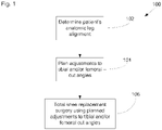
- FIG. 1 With reference to Figure 1 , there is shown a high level flowchart illustrating various stages of an overall method 100 of preparing for, planning and conducting total knee replacement surgery 100. Aspects of the disclosure may reside in the overall method 100, the individual stages thereof, combinations of the individual stages and combinations of sub-stages of the stages illustrated in Figure 1 .
- An initial stage 102 of the overall method involves determining the patient's pre-operative anatomical legal alignment 102. This may be carried out in a number of ways, as described in greater detail below, and essentially involves determining the hip, knee, ankle axes of the patient's leg and also the knee joint line. Anatomical information derived from the patient's actual leg are obtained at this initial step 102.
- a planning method is carried out.
- the planning method carried out at step 104 uses the patient's anatomic leg alignment information obtained in step 102 to determine any angular adjustments to be made to femoral and / or tibial cuts.
- the result of planning step 104 are planned tibial and / or femoral cut angles which can then be used in the actual surgical procedure carried out at step 106.
- a total knee replacement surgical procedure is carried out using the tibial and femoral cut positions determined from planning surgery 104 which may include adjustments to the tibial and / or femoral cut angles compared to those used in conventional procedures.
- the tibial and / or femoral cut angles planned at stage 104 implement a surgical philosophy underlying the surgical method step 106 that the femur is the key kinematic driver of the knee. Therefore, an improved functional restoration of the patient's knee can be achieved by resurfacing the femur within the constraints of maintaining the long leg alignment and tibial cuts angles within safe boundaries.
- the pre-operative surgical planning method carried out at step 104 allows a pre-operative surgical plan to be developed that can restore the natural joint line within predefined safe boundaries of the varus or valgus angle of the tibial cut, restores the long leg alignment of the patient within predefined safe boundaries for the hip-knee-ankle axis and may also restore the natural posterior femoral condyles within predefined boundaries of femoral rotation.
- the planning method of step 104 recognises that the long leg alignment of the patient is dependent on the distal femoral cut angle and tibial cut angle.
- the method enables calculation of a one of these variables based on second safe target ranges for the other two.
- the angle of the distal femoral cut and / or tibial cut can be modified to ensure that they stay within predefined ranges of values. Any adjustment to the tibial cut angle can be applied also to the femoral rotation of the knee in flexion.
- the planned femoral and tibial cut angles are then used as input to the surgical procedure 106.
- Surgical procedure 106 is then largely conventional and may use largely conventional instrumentation in order to carry out the total knee replacement surgery.
- the angles at which the tibial and / or femoral cutting blocks are set relative to the femur and / or tibia differ to those that would otherwise be used.
- the surgical method 106 can also use any prosthetic knee implant system comprising femoral and tibial components intended for use in anatomy based surgical procedure.
- a suitable set of instruments include the Intuition instruments described in the Attune surgical knee system surgical technique document available from DePuySynthes, a Johnson & Johnson company (Intuition is a Trade Mark of DePuySynthes).
- the knee implants used may be the Attune knee system implants also available from DePuySynthes and also described in the Attune knee system surgical technique document available from DePuySynthes (Attune is a Trade Mark of DePuySynthes which may be registered in some countries).
- the invention is not limited to either very specific implants or the specific instruments of the Attune knee system. Rather, any instrumentation allowing the angle of the distal femoral cut to be adjusted relative to the femur and the tibial cut to be adjusted relative to the tibia can be used.
- step 106 An exemplary surgical procedure corresponding to step 106 is described in greater detail below.
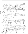
- Figure 2A shows a neutral leg alignment 200.
- a neutral leg alignment is characterised by the load bearing axis extending from the centre of the femoral head 202 to the centre of the ankle 204, represented by solid line 206, passing through the centre of the patient's knee.
- Also illustrated in Figure 2A as a dash dot line 208, is the approximate axis of the intramedullary canal of the distal end of the femur, and which represents the distal femoral anatomical axis.
- Figure 2A shows the patient's leg alignment in a standing, loaded condition in which the weight of the patient's body passing along the long leg axis 206.
- the joint line 209 of the patient's knee is also shown in Figure 2A.
- the joint line 209 is generally parallel to the floor on which the patient is standing and typically approximately 3° offset from perpendicular to the long leg axis 206.
- the angle subtended between the joint line 209 and the long leg axis 206 on the medial side, and inferior to the joint line, and marked ⁇ in Figure 2A is typically approximately 87°.
- Figure 2A shows the various axes of the patient's leg projected on to the frontal plane of the body.
- Figure 2B is similar to Figure 2A but shows a leg having a varus alignment.
- the long leg axis 206 extends from the centre of the femoral head 202 to the centre of the ankle 204.
- a hip-knee axis 214 also known as the femoral mechanical axis is defined by the line passing from the centre of the femoral head 202 to the centre of the knee 212.
- the knee-ankle axis 216 also known as the tibial mechanical axis is defined by the line running from the centre of the knee 212 to the centre of the ankle 204.
- the hip-knee-ankle axis defined by lines 214 and 216 is no longer co-linear with the long leg axis 206 as is the case in the neutral alignment illustrated in Figure 2A .
- the angle on the medial side subtended between the hip-knee axis 214 and knee-ankle axis 216 is less than 180°.
- the angle on the lateral side between the hip-knee axis 214 and knee-ankle axis 216 is greater than 180°.
- line 208 represents the alignment of the intramedullary canal at the distal end of the femur.
- the hip-knee axis, or mechanical axis of the femur, 214 can be considered to extend from the centre of the femoral head to the mid-condylar point between the cruciate ligaments of the knee.
- the knee-ankle axis, or the mechanical axis of the tibia, 216 can be defined by the line from the centre of the tibial plateau to the centre of the tibial plafond.
- Figure 2C shows a valgus leg alignment 220.
- the femoral mechanical axis 214 and tibial mechanical axis 216 are no longer co-linear with the long leg axis 206.
- the long leg axis 206 falls laterally of the knee for a valgus alignment whereas the long leg axis 206 falls medially of the knee for a varus alignment as shown in Figure 2B .
- the angle subtended by the femoral mechanical axis 214 and tibial mechanical axis 216 medially of the knee is greater than 180° and the angle subtended by the femoral mechanical axis 214 and tibial mechanical axis 216 on the lateral side is less than 180°.
- the joint line of the knee, 209 can generally be considered to be the line tangential to the distal most parts of the medial and lateral condyles.
- the joint line 209 is substantially parallel to the floor however, the angle of the joint line relative to the mechanical axes of the tibia and femur of the knee varies in the varus and valgus alignments as will be appreciated by a person of ordinary skill in the art.
- a first anatomical information gathering stage 102 information is obtained from the patient's body, either directly or indirectly, sufficient to establish the femoral mechanical axis 214, the tibial mechanical axis 216 and the joint line 209.
- Indirect approaches typically involve capturing an image of the patient's bones and determining the positions of various anatomical landmarks in the bone images in order to determine the required anatomical alignment information.
- a long leg x-ray may be taken of the patient in a standing, loaded position.
- the x-ray may involve the capture of one or a plurality of x-rays which overlap, sufficient to allow the various anatomical landmark positions to be determined.
- the centre of the femoral head 202 can be determined as well as the centre of the knee, the centre of the ankle and also the joint line 209 corresponding to the line tangential to the distal most parts of the medial and lateral condyles.
- image processing routines may be used on digitised images of the x-rays or digital x-rays themselves in order to manually, automatically or semi automatically determine the required angle information.
- three dimensional modelling and/or computer simulation software may be used and CT scan data may be processed to determine the required anatomical information.
- the positions of various anatomical landmarks on the patient are determined directly on the patient themselves. This may be done by palpating the patient and measuring various distances.
- computer assisted surgery techniques may be used in which trackable markers are attached to the patient's bones and / or instruments so as to capture the position of various anatomical landmarks by placing a trackable pointer on those landmarks.
- the determination of the patient's anatomical information may be carried out as part of a surgical procedure itself, rather than a purely pre-operative step, as access to the interior of the patient's knee may be required.
- Computer assisted surgery methods for determining the centre of rotation of the femoral head are generally known in the art. Examples of these include attaching a trackable marker to the patient's knee, rotating the femur about the hip joint and capturing the locus traced by the trackable marker. From this, the centre of rotation of the hip, corresponding to the centre of the femoral head can be determined.
- an x-ray may be captured with the lower leg in a stressed position so that the patient's knee adopts an alignment similar to that it would have in the absence of the disease condition and which can be considered more accurately to correspond to the original anatomy of the patient's knee rather than the disease state.
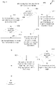
- FIG 3 shows a process flow chart illustrating a total knee replacement planning method 300 according to an aspect of the invention and corresponding generally to step 104 of Figure 1 .
- Planning method 300 corresponds to a femur based planning approach which aims to maintain the angle of the femoral cut as parallel to the joint line, if possible, by modifying the tibial cut angle, if necessary, to ensure that the tibial cut angle and leg alignment are both within safe boundaries. If this cannot be done by modifying the tibial cut angle alone, then the femoral cut angle can also be modified to ensure compliance with the tibial cut angle and long leg angle safe boundaries.
- a tibia based planning approach is also possible and is described later with reference to Figure 8 .
- Method 300 may be implemented in a number of different ways.
- method 300 may be implemented in software as part of a more general surgical planning computer program 940 which may be associated with a computer assisted surgery (CAS) system 950 or may be a standalone computer program dedicated to this purpose only, for example as an application on a smart phone or tablet or other general purpose computing device.
- CAS computer assisted surgery
- method 300 may be implemented as a set or rules, or guidelines or a flow chart on printed media to which a surgeon may refer to in order to carry out the method and enter various measurements, values and calculations used in the method.
- the planning method 300 does not also plan the height of the cuts as this is not important in realising the benefits of the method, the heights or depths of the cuts may depend on the size of the implants used, the soft tissues of the knee and other factors and the heights or depths of the cuts may be determined as for a conventional total knee replacement surgical procedure.
- An initial step 302 of the planning method 300 involves setting boundaries for the long leg alignment angle and the angle of the proximal tibial cut.
- the angle between the femoral mechanical axis and tibial mechanical axis is substantially 180°.
- a range of acceptable leg alignment values is defined.
- the range of acceptable angles may be 3°
- the boundary values may be 177° and 180°.
- ⁇ the magnitude of the angle subtended by the femoral mechanical axis and the tibial mechanical axis on the medial side of the knee will be used and will be referred to herein as ⁇ .
- ⁇ being greater than 180° corresponds to valgus alignment and ⁇ being less than 180° corresponds to varus alignment.
- the choice of the definition of the angle used to define the long leg alignment is largely arbitrary.
- a variation of up to 10° away from neutral alignment will still provide reasonable mechanical performance of the tibial and femoral components of the prosthetic knee.
- a variation of up to not more than 3° may be used as the boundaries or limits of the long leg alignment of the patient's leg.
- the long leg alignment boundaries are set such that 177° ⁇ ⁇ ⁇ 180°, and hence corresponding to neutral to varus alignments.
- Figure 4 shows a schematic diagram of a patient's pre-operative knee joint 400 and includes the distal part of the femur 402 and the proximal part of the tibia 404. Also shown is the femoral anatomical axis 208 adjacent the distal part of the femur and corresponding generally to the femoral intramedullary canal. The anatomical axis of the tibia is largely coincidental to the mechanical axis of the tibia 216.
- the medial condyle is 406, the lateral condyle is 408 and the angle ⁇ is subtended by the femoral mechanical axis 214 and the tibial mechanical axis 216.
- the joint line 209 is tangential to the distal most parts of the medial 406 and lateral 408 condyles.
- the joint line angle can generally be defined as the angle, on the medial side, subtended between the joint line 209 and tibial mechanical axis 216 and inferior to the joint line.
- the tibial cut angle can be defined as the angle subtended between the tibial cut line 410 and the tibial mechanical axis 216 inferior to the joint line and is labelled ⁇ in Figure 4 .
- the definition of the tibial cut angle is again largely arbitrary and other definitions are possible, such as the angle subtended between the tibial cut line and tibial mechanical axis superior to tibial cut line 410.
- a distal femoral cut angle, ⁇ can also be defined as the angle subtended between the distal femoral cut line 412 and the femoral mechanical axis 214. Again the definition of the distal femoral cut angle ⁇ is largely arbitrary, and other definitions are possible.
- the joint line 209 is generally parallel to the floor and approximately 3 ° offset from perpendicular to the tibial mechanical axis (which is coincident with the long leg axis 206 for neutral alignment).
- the purely anatomical surgical philosophy is to simply make the tibial cut line 410 parallel to the patient's joint line 209, thereby replicating the knee geometry of neutral alignment.
- the planning method 300 instead sets a range of acceptable values for the angle of the tibial cut. In this example, the range of values is not more than 3° less than perpendicular to the tibial mechanical axis, i.e.
- leg alignment angle and tibial cut angle are both 3°. In other embodiments, the magnitudes of the ranges of values may be different for leg alignment angle and tibial cut angle.
- the range of acceptable angles for the long leg alignment and the proximal tibial cut angle set at step 302 may be based on a number of approaches either individually or in combination.
- Theoretical and/or empirical approaches may be used. For example, a more empirical approach would be to analyse survivorship data for implants in different patients and correlate that with the post-operative long leg alignment angles and/or tibial cut angles arising for the patients' implants.
- a more theoretical approach would be to use computer analysis of computer models of the patient's leg and knee implant to determine the distribution, direction and size of various forces.
- Another more empirical approach would be to measure the forces arising in a prosthetic knee for different long leg alignment angles to determine the effect of long leg alignment angle and/or proximal tibial angle on the forces in the prosthetic knee joint and/or exerted by the prosthetic knee joint on the patient's resected tibia and/or femur.
- the results of theoretical and empirical approaches may be combined to help determine the pre-selected ranges of angles used at step 302.
- the definitions of the various angles are arbitrary to an extent.
- the boundaries of the ranges of values of the long leg angle and tibial cut angle are set at step 302.
- this may be a direct comparison, if the ranges and angles are defined in the same way or it may be an indirect comparison, if the ranges and angels are defined in different way.
- This direct or indirect comparison is covered by determining whether the various angles correspond to an angle falling within or outside the ranges. Hence, this encompasses situations in which the definitions are the same or differ, in which case a transformation may need to be applied to make the angles directly comparable with the ranges, for example adding or subtracting 180° or 90 °.
- the definitions of the angles and values used in the ranges are the same and therefore allow a direct comparison when determining whether various angles correspond to an angle within the first or second ranges of values set at 302.
- the patients anatomical data obtained previously at step 102 is used to determine whether the patient's long leg alignment is with the boundaries set at step 302.
- the method proceeds to step 306 at which initial planned femoral cut and tibial cut angles are set.
- the initially planned tibial cut angle is set to an angle that would restore the joint line 209 of the patient.
- the initially planned tibial cut angle between the tibial cut line 410 and the tibial mechanical axis 216, is set to make the tibial cut line 410 parallel to the joint line 209, which in this example is 89°.
- the initially planned femoral cut angle ⁇ is set to a value such that the distal femoral cut line 412 is parallel to the joint line and in this case also to the initially planned tibial cut line 410'.
- the initially planned femoral cut angle is 89°.
- step 308 it is determined if the initially planned value for the tibial cut angle is within the boundaries set at step 302. Hence, step 308 determines whether, the initially planned tibial cut angle value of 89° is between 87° and 90° which it is. Hence, at step 310 the final planned femoral cut angle value is set to the initially planned value of 89° and the final planned tibial cut value is set to the initially planned value of 89° and planning is complete. Hence, the initially planned tibial and distal femoral cut angles have been validated by the planning method as being acceptable final planned cut angles.
- FIG. 5 shows a different patient's knee geometry 500.
- the value of the angle ⁇ between the femoral mechanical axis 214 and the tibial mechanical axis 216 is again 178° and so the method proceeds at step 304 to step 306.
- the angle between the joint line 209 and the tibial mechanical axis 216 is 86°.
- the initially planned tibial cut angle value to restore the patient's joint line 209 will be 86° (so that the tibial cut line 410 is parallel to the joint line 209).
- the initially planned femoral cut angle value is set so that the femoral cut line 412 is also parallel to the joint line 209.
- the initially planned femoral cut angle value is 92°.
- the initially planned tibial cut angle value is set to the boundary value closest to the initially planned value, i.e. to 87° at step 314.
- an adjustment angle of 1° is applied to the initially planned tibial cut angle to arrive at the final planned tibial cut angle. This is illustrated in Figure 5 , by the corresponding final planned tibial cut line 414 which is no longer parallel to joint line 209 (and which is exaggerated in Figure 5 for clarity of explanation).
- the finally planned femoral cut angle is set to the initially planned femoral cut angle but adjusted by the tibial cut adjustment angle of 1°.
- the value of the finally planned femoral cut angle is set to 91° and gives rise to a corresponding finally planned femoral cut line 416 which is no longer parallel to joint line 209, but is parallel to finally planned tibial cut line 414 and hence does not change the leg alignment of the patient.
- the finally planned tibial cut angle and distal femoral cut angles no longer provide exact replication of the pre-operative patient anatomy, as the resulting joint line will be 1° rotated compared to original anatomic joint line 209, but they are as close as possible within the boundaries set.
- the long leg alignment has not been altered and therefore this aspect of the patient's anatomy will be preserved by these planned cut angles.
- the initially planned femoral cut angle is modified only if the initially planned tibial cut angle is outside of the acceptable range.
- a third example illustrates the planning method 300 further.
- Figure 6 shows a different patient's knee geometry 600.
- the value of the angle ⁇ between the femoral mechanical axis 214 and the tibial mechanical axis 216 is 176°.
- the method 300 proceeds to step 316.
- the initially planned femoral cut angle is set to restore the joint line 209.
- the initially planned femoral cut angle is set to a value of 87° so that the corresponding initially planned femoral cut line 418 is parallel to joint line 209.
- an initially planned tibial cut angle is set which will bring the long leg alignment back within the boundary set in step 302.
- a 1° rotation is added to the initially planned tibial cut angle, which is illustrated in Figure 6 , by the initially planned tibial cut line 420 being rotated by 1° relative to a line 422 parallel to the joint line 209.
- the initially planned tibial cut angle value is therefore 90°.
- step 318 it is determined whether the initially planned tibial cut angle is within the tibial cut angle boundaries set in step 302, which in this example it is.
- step 320 the value of the finally planned femoral cut angle is set to the initially planned value of 87° and the value of the finally planned tibial cut angle is set to the initially planned value, which includes the 1° adjustment, of 91°.
- the leg alignment angle ⁇ has been increased by 1° and hence the long leg alignment has been brought back within the acceptable range.
- a fourth example illustrates the planning method 300 further.
- Figure 7 shows a different patient's knee geometry 700.
- the value of the angle ⁇ between the femoral mechanical axis 214 and the tibial mechanical axis 216 is 176°.
- the method 300 proceeds to step 316.
- the initially planned femoral cut angle is set to restore the joint line 209.
- the initially planned femoral cut angle is set to a value of 91° so that the corresponding initially planned femoral cut line 424 is parallel to joint line 209.
- an initially planned tibial cut angle is set which will bring the long leg alignment back within the boundary set in step 302.
- a 1° rotation is added to the initially planned tibial cut angle, which is illustrated in Figure 7 , by the initially planned tibial cut line 426 being rotated by 1° relative to a line 428 parallel to the joint line 209.
- the initially planned tibial cut angle value is therefore 86°.
- the method proceeds to step 322 at which the value of the finally planned tibial cut angle is set to the closest tibial cut boundary, being 87°, and therefore including an adjustment angle of 1°.
- This is illustrated in Figure 7 , by corresponding finally planned tibial cut line 430, being rotated by a further 1° from the initially planned tibial cut line 426.
- the method proceeds to step 324 at which the value of the finally planned femoral cut angle is set to the initially planned femoral cut angel but adjusted by the tibial cut angle adjustment of 1° needed to bring the tibial cut angle back within the acceptable range.
- the finally planned femoral cut angle is set to the value of 92°.
- the embodiment of the planning method illustrated in Figure 3 prioritises the angle of the distal femoral cut as the method tries to maintain the femoral cut line parallel to the joint line, and preferentially modifies the angle of the tibial cut.
- the tibial cut angle rather than the femoral cut angle, is used to modify the long leg alignment axis if that is outside its boundaries.
- the femoral cut angle is only modified in cases where the tibial cut angle would otherwise be outside its boundaries, in which case the femoral cut angel is adjusted by the same amount of angle as the tibial cut angle is adjusted to bring it back within its boundaries.
- the method may also be implemented as a tibial cut prioritised plan using a similar approach but in which the proximal tibial cut angle is preserved as an anatomical cut (i.e. to recreate the joint line) unless needed in order to keep the tibial cut angle within the acceptable boundaries.
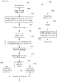
- the tibial based planning method 800 is illustrated by the flow chart shown in Figure 8 .
- the planning method 800 illustrated in Figure 8 uses the same overall approach as the planning method 300 illustrated in Figure 3 of setting leg alignment and tibial cut boundaries and then checking that the tibial cut angle and leg length alignment fall within those boundaries, and if not then adjusting the tibial cut and/or femoral cut angles so that the finally planned tibial and femoral cut angles result in a knee joint geometry that does fall within those boundaries.
- the approach of the method 800 differs in that it initially sets the tibial cut angle as the finally planned tibial cut angle and then only the femoral cut angle is subsequently adjusted, if necessary to bring the leg length alignment within its acceptable boundaries.
- the boundaries of the leg length alignment are set, e.g. 177° ⁇ ⁇ ⁇ 180°, and the boundaries of the tibial cut angle relative to the tibial mechanical axis are set, e.g. 87° ⁇ ⁇ ⁇ 90°.
- the angle between the joint line and the tibial mechanical axis is compared to the tibial cut angle boundaries, to see if an anatomical approach, i.e. the tibial cut replicating the patient's joint line, is acceptable.
- the planned tibial cut angle is set to the angle resulting in the tibial cut line being parallel to the joint line and also the initially planned femoral cut angle is set so that the distal femoral cut line will also be parallel to the joint line.
- the finally planned femoral cut angle is set to the initially planned femoral cut angle but adjusted to bring the long leg alignment back within the boundaries at 812. For example, if the angle between the patient's femoral mechanical axis and tibial mechanical axis is 175°, then a 2° adjustment at least is needed to bring the long leg alignment back within the boundaries. Hence, at step 812, a 2° adjustment is made to the initially planned femoral cut angle and that value is then used as the finally planned femoral cut angle. Hence, planning is complete and results in an anatomy preserving tibial cut, but a slight change in the long leg alignment of the patient.
- the tibial cut angle is planned as being the closest boundary value, i.e. 87°. It will be appreciated that by choosing the closest boundary value, as is also done in method 300, the adjustments made away from the patient's anatomy are minimised, thereby helping to preserve the benefits arising from anatomy based surgical philosophies. Also at 814, the initially planned femoral cut angle is set to that needed to restore the joint line, but also including the tibia cut adjustment angle.
- the initially planned femoral cut angle is set as including the 2° tibial adjustment angle at 814.
- the planned tibial cut line and initially planned femoral cut line are parallel at this stage of the method.
- the long leg alignment angle has now been adjusted, by 2° in this example.
- the method proceeds to 818 and the planned femoral cut angle is set to the initially planned femoral cut angle, which includes the 2° adjustment.
- the planned tibial cut line is left as close as the boundaries allow to the anatomical cut line, and a minimal adjustment to the long leg alignment so as to be within the acceptable boundaries has been introduced.
- the method proceeds to 820 and the planned femoral cut angle is set to the initially planned femoral cut angle but including an angular adjustment to bring the long leg alignment back within the boundaries.
- a further 1 adjustment is added to the initially planned femoral cut angle, to bring the corresponding long leg alignment axis to 177° and therefore within the boundary.
- the planned tibial cut line is left as close as the boundaries allow to the anatomical cut line, and a minimal adjustment to the long leg alignment so as to be within the acceptable boundaries has been introduced, but which is slightly greater than that of the preceding example.
- the planning methods 300 and 800 may be embodied or implemented in a printed medium which bears instructions readable by a user and guiding the user through the steps of the planning methods 300 and 800 illustrated in Figures 3 and 8 , or other steps which ultimately implement the planning method of the disclosure as illustrated by the specific methods of Figures 3 and 8 .
- the instructions may include written instructions as well as instructions in graphical form, such as one or more diagrams of a knee joint showing the various axes and angles used in the planning methods 300, 800.
- the printed medium may also bear an indication of the first pre-selected range of values, e.g. 177° ⁇ ⁇ ⁇ 180°, and the second pre-selected range of values, 87° ⁇ ⁇ ⁇ 90°.
- the medium may also include one or more first fields where a user can record a first type of data.
- the first type of data may be anatomical data derived from the patient and may include the angle of the femoral mechanical axis, the angle of the tibial mechanical axis, the angle between the femoral mechanical axis and the tibial mechanical axis, the angle of the joint line, the angle between the joint line and the femoral mechanical axis and/or the angle between the joint line and the tibial mechanical axis.
- the anatomical data should include at least enough data to allow the angles of the joint line relative to the tibial mechanical axis to be determined and also the angle between the tibial and femoral mechanical axes.
- the medium may include one or more second fields where a user can record the result of a calculation.
- the result of the calculation may be a value of an angle.
- fields may be provided near instructions to add or subtract various angles to enter the result of that calculation so as to maintain a record of the initially planned angles, any angular adjustments applied by following the planning methods and also the resulting finally planned tibial and femoral cut angles.
- the surgical method 106 may be carried out using the Attune Knee System and Intuition instruments as provided by DePuySynthes and as described in the Attune Knee System Surgical Technique document also provided by DePuySynthes (ATTUNE is a Trade Mark of DePuySynthes, which is registered in some countries and INTUITION is a Trade Mark of DePuySynthes).
- ATTUNE is a Trade Mark of DePuySynthes, which is registered in some countries and INTUITION is a Trade Mark of DePuySynthes).
- the surgical method may be carried out using a computer assisted surgery (CAS) system 950, for example as illustrated in Figure 9 .
- CAS systems are generally known and typically including a computer system 952, tracking system 954 and a display 956 which provides visual and other guidance to the surgeon to guide them through the various steps of the workflow of the surgical procedure and also provides guidance as to the relative positions of tools, instruments, implants and body parts, represented by 958, 960, 962, to asset in the carrying out of various acts, such as positing instrumentation, making cuts, and placing trial components and prosthetic components.
- the body parts and the tools, instruments and implants used in the CAS system may include one or more markers 964 which are trackable by the tracking system 954 which provides positional information or data 966 to the computer system 952.
- a CAS system may including software 942 which configures the CAS system to assist the surgeon to carry out the surgical steps illustrated in Figure 9 .
- the CAS system may also include planning software 940 which configures the CAS system to implement the planning method used at step 104.
- the tibial and femoral cut planning data generated by the planning software 940 may be passed to the surgery workflow software 942 and used by the surgery workflow software 942 to provide an indication of the planned position of the tibial and femoral cuts and any angular adjustments or settings to be used with the femoral and tibial cutting block so as to reproduce the planned tibial and femoral cut positions on the display 956.
- the tracking system 954 is shown separately in Figure 9 for the sake of explanation, it will be appreciated that the tracking system 954 can be integrated into the computer system 952 to provide a unified CAS system 950 in other embodiments.
- the surgical method 900 begins at 902 by opening the patent's knee with the patient's leg generally extended.
- a femoral cutting block may be attached to the patient's femur. This may involve drilling a hole into the distal end of the femur to access the femoral intramedullary canal which defines the local anatomical axis of the femur.
- An intramedullary rod with an angle adjustable jig is connected to a distal femoral cutting block inserted into the intramedullary canal.
- a suitable arrangement is the distal femoral jig assembly as shown in the Attune Surgical Technique document.
- the anatomical axis of the femur 208 is offset from the mechanical axis of the femur 214 by an angle that varies from patient to patient, depending largely on the length of their femur.
- the angle is typically about 3° - 4°, for a medium femur typically about 5°, and for a longer femur, typically about 6° - 7°.
- the angular offset between the anatomical axis 208 and the mechanical axis is taken into account in determining the angel to be set using the adjustable jig so as to set the correct planned position of the distal cutting block.
- the angular position of the cutting block is typically defined relative to the anatomical axis (along which the intramedullary rod passes), such that a zero degree angle of the adjustment jig corresponds to the distal cut line being perpendicular to the femur's anatomical axis.
- the angle of the jig is adjusted so as to place the distal femoral cutting block so that the distal femoral cut line corresponds to the planned distal femoral cut angle, taking into account the offset between the mechanical axis and anatomical axis of the femur.
- the depth of the femoral cut will depend on the size of the implant being used and is often in the range of 4 to 16 mm, with 8-11mm being typical.
- the distal femoral cutting block is then pinned in position, the femoral jig and IM rod removed and then the distal femoral cut is made at 908.
- the tibial cutting block is attached to the tibia.
- the tibial mechanical axis and anatomical axis are usually coincidental and so usually there is no angular off set to be taken in to account for the tibial cutting block adjustment.
- a tibial alignment guide can be used to position and attach the tibial cutting block.
- a stable tibial alignment guide is described in the Attune Surgical Technique document.
- the tibial alignment guide is attached to the lower leg of the patient by attaching a first end to the patient's ankle and aligned with the second toe of the patient's foot and the mechanical axis of the tibia.
- a tibial cutting block is attached to the second end of the alignment guide and includes a central aperture through which a bone pin is placed aligned with the centre or midpoint of the knee.
- the medial-lateral position of the first end of the alignment guide is adjustable and when varied causes the tibial cutting block to pivot about the bone pin.
- the angle of the tibial cutting block can be adjusted by changing the medial-lateral position of the first end of the tibial alignment guide, until the cutting block angle corresponds to the planned tibial cut line.
- the tibial cutting block is then pinned in place and the proximal cut is made at 914.
- steps 904 to 908 may be carried out after steps 910 to 914, with any appropriate modifications to the surgical steps resulting therefrom, and which modifications will be apparent to a person of ordinary skill in the art.
- the distal femoral cut and proximal tibial cuts have now been made, but using the planned cut orientations obtained from the planning step 104 rather than conventionally planned positions.
- the planed tibial an femoral cut orientations help to ensure proper mechanical operation of the prosthetic knee while also maintaining the long leg alignment and anatomy of the patient as much as possible.
- a spacer instrument may be inserted into the extension gap between the resected tibia and femur to assess the gap and any soft tissue release may be carried out to provide balance with the knee in extension. Soft tissue release may be more likely to be required in instances where the long leg alignment has been altered.
- the knee may be articulated into flexion to allow femoral sizing and rotation to be assessed.
- Two different approaches may be used.
- a measured femoral sizing and rotation approach may be used as indicated by step 920.
- a measured femoral sizing and rotation guide as described in the Attune Surgical Technique document may be used.
- the size of the femur may be determined and the position of the femoral cutting block used to make the rest of the femoral cuts can be determined.
- a stylus attached to the guide can be used to determine the size of the femur.
- the guide is angle adjustable to allow the angular position of the femoral cutting block to be set on the resected distal femoral surface.
- the rotation of the femur is defined by the line tangential to the posterior most parts of the lateral and medial condyles.
- the angular relationship between this line and the plane of the resected proximal tibia is generally desirable for the angular relationship between this line and the plane of the resected proximal tibia to be kept the same.
- an angular adjustment of the tibial cut was introduce during planning, e.g. 3°, to bring the tibial cut angle and/or the long leg alignment back within their boundaries, then the same angular adjustment is added to the femoral rotation.
- the femoral cutting block is rotated by an extra 3° to maintain the angular relationship between the posterior part of the condyles and the plane of the proximal tibial surface before being pinned to the resected distal femur.
- a feature of the planning method may also include planning an angle of a posterior femoral cut to set the femoral rotation and which includes any angular adjustments made to the tibial cut angle during the planning method 104.
- step 920 An alternative to step 920 is to use a balanced approach, rather than a measured approach, to femoral sizing and rotation at step 922.
- a balancing device for example including a pair of spreaders, is used and introduced into the flexion gap to apply an equal force to the posterior parts of the medial and lateral condyles. The surgeon then positions a cutting block at an angle such that, when the posterior condyles are under load, the posterior cut is generally parallel to the plane of the resected tibial surface.
- the soft tissue structure define the femoral rotation rather than the angle of the posterior femoral cut.
- the posterior femoral cut is made at 924.
- a spacer block may be inserted in the flexion gap and the balance of the joint may be assessed and any soft tissue release carried out to improve the balance of the joint.
- the rest of the surgical procedure is then largely conventional.
- the remaining femoral cuts are made at 926 to complete preparation of the femur.
- Trial implants may be attached during a trialling stage 928 and a trial reduction of the joint carried out. As will be appreciated trialling can give rise to iterative changes to the cuts and/or soft tissues until the surgeon is happy.
- the prosthetic tibial and femoral components are implanted at 930 and then the knee is closed 932.
- the disclosure may include various operations from each of the general patient data acquisition 102, planning 104 and surgical method 106 steps of Figure 1 .
- the planning method may be implemented in a variety of ways ranging from software to printed media providing instructions to guide a user through the planning method and/or including fields for entering information or data and/or carrying out calculations to determine the planned tibial and femoral cut angles.
- aspects of the disclosure may employ various processes involving data stored in or transferred through one or more computer systems.
- aspects of the present disclosure also relate to an apparatus for performing these operations.
- This apparatus may be specially constructed for the required purposes, or it may be a general-purpose computer selectively activated or reconfigured by a computer program and/or data structure stored in the computer.
- the processes presented herein are not inherently related to any particular computer or other apparatus.
- various general-purpose machines may be used with programs written in accordance with the teachings herein, or it may be more convenient to construct a more specialized apparatus to perform the required method steps.
- aspects of the present disclosure relate to computer readable media or computer program products that include program instructions and/or data (including data structures) for performing various computer-implemented operations.
- Examples of computer-readable media include, but are not limited to, magnetic media such as hard disks, floppy disks, and magnetic tape; optical media such as CD-ROM disks; magneto-optical media; semiconductor memory devices, and hardware devices that are specially configured to store and perform program instructions, such as read-only memory devices (ROM) and random access memory (RAM).
- Examples of program instructions include both machine code, such as produced by a compiler, and files containing higher level code that may be executed by the computer using an interpreter.
- FIG 11 illustrates a typical computer system that, when appropriately configured or designed, can serve as a planning computer or CAS computer or part of a CAS system according to the invention.
- the computer system 970 includes any number of processors 972 (also referred to as central processing units, or CPUs) that are coupled to storage devices including primary storage 976 (typically a random access memory, or RAM), primary storage 974 (typically a read only memory, or ROM).
- processors 972 may be of various types including microcontrollers and microprocessors such as programmable devices (e.g., CPLDs and FPGAs) and unprogrammable devices such as gate array ASICs or general purpose microprocessors.
- primary storage 974 acts to transfer data and instructions uni-directionally to the CPU and primary storage 976 is used typically to transfer data and instructions in a bi-directional manner. Both of these primary storage devices may include any suitable computer-readable media such as those described above.
- a mass storage device 978 is also coupled bi-directionally to CPU 972 and provides additional data storage capacity and may include any of the computer-readable media described above. Mass storage device 978 may be used to store programs, data and the like and is typically a secondary storage medium such as a hard disk. It will be appreciated that the information retained within the mass storage device 978, may, in appropriate cases, be incorporated in standard fashion as part of primary storage 497 as virtual memory.
- a specific mass storage device such as a CD-ROM 974 may also pass data uni-directionally to the CPU.
- CPU 972 is also coupled to an interface 980 that connects to one or more input/output devices such as such as video monitors, track balls, mice, keyboards, microphones, touch-sensitive displays, transducer card readers, magnetic or paper tape readers, tablets, styluses, voice or handwriting recognizers, or other well-known input devices such as, of course, other computers.
- CPU 972 optionally may be coupled to an external device such as a tracking system, a database or a computer or telecommunications network using an external connection as shown generally at 982. With such a connection, it is contemplated that the CPU might receive information from the tracking system, network, or might output information to the tracking system, network or other device in the course of performing the method steps described herein.
Landscapes
- Health & Medical Sciences (AREA)
- Surgery (AREA)
- Life Sciences & Earth Sciences (AREA)
- Engineering & Computer Science (AREA)
- General Health & Medical Sciences (AREA)
- Veterinary Medicine (AREA)
- Nuclear Medicine, Radiotherapy & Molecular Imaging (AREA)
- Public Health (AREA)
- Animal Behavior & Ethology (AREA)
- Molecular Biology (AREA)
- Biomedical Technology (AREA)
- Heart & Thoracic Surgery (AREA)
- Medical Informatics (AREA)
- Physical Education & Sports Medicine (AREA)
- Transplantation (AREA)
- Orthopedic Medicine & Surgery (AREA)
- Dentistry (AREA)
- Oral & Maxillofacial Surgery (AREA)
- Robotics (AREA)
- Prostheses (AREA)
- Surgical Instruments (AREA)
Claims (11)
- Dispositif de traitement de données (970) comprenant :un processeur de données (972) ; etun support lisible par ordinateur (976) stockant un code de programme informatique sous une forme non temporaire, et dans lequel le code de programme informatique est exécutable par le processeur de données pour réaliser une méthode mise en œuvre par ordinateur (300) de détermination d'un angle de coupe tibial proximal planifié et d'un angle de coupe fémoral distal planifié à utiliser dans une intervention chirurgicale d'arthroplastie totale du genou sur un genou d'une jambe d'un patient, comprenant :la définition (302) d'une première plage de valeurs présélectionnée pour un angle à jambe allongée entre l'axe mécanique tibial et l'axe mécanique fémoral ;la définition (302) d'une seconde plage de valeurs présélectionnée pour un angle de coupe tibial proximal ; etla détermination d'un angle de coupe tibial proximal planifié et d'un angle de coupe fémoral distal planifié en utilisant des données anatomiques obtenues du patient qui définissent l'axe mécanique tibial, l'axe mécanique fémoral et la ligne articulaire du genou du patient, dans lequel la détermination de l'angle de coupe tibial proximal planifié et de l'angle de coupe fémoral distal planifié inclut :la détermination (304) de la correspondance ou non de l'angle à jambe allongée avec un angle tombant à l'intérieur de la première plage de valeurs présélectionnée ;si l'angle à jambe allongée correspond à un angle tombant à l'intérieur de la première plage de valeurs présélectionnée, alors la définition (306) d'un angle de coupe tibial proximal initialement planifié pour restaurer la ligne articulaire et d'un angle de coupe fémoral distal initialement planifié pour restaurer la ligne articulaire ;si l'angle à jambe allongée ne correspond pas à un angle tombant à l'intérieur de la première plage de valeurs présélectionnée, alors la définition (316) d'un angle de coupe tibial proximal initialement planifié pour ajuster l'angle à jambe allongée pour qu'il corresponde à un angle tombant à l'intérieur de la première plage de valeurs présélectionnée et d'un angle de coupe fémoral distal initialement planifié pour restaurer la ligne articulaire ;la détermination (308, 318) de la correspondance ou non de l'angle de coupe tibial proximal initialement planifié avec un angle tombant à l'intérieur de la seconde plage de valeurs présélectionnées ; etla définition (310, 320) de l'angle de coupe fémoral distal planifié à l'angle de coupe fémoral distal initialement planifié et de l'angle de coupe tibial proximal planifié à l'angle de coupe tibial proximal initialement planifié lorsqu'il est déterminé que l'angle de coupe tibial proximal initialement planifié correspond à un angle tombant à l'intérieur de la seconde plage de valeurs présélectionnées ; oula définition (312, 322) de l'angle de coupe tibial proximal planifié à l'angle de coupe tibial proximal initialement planifié modifié par un angle d'ajustement amenant l'angle de coupe tibial proximal planifié à correspondre à un angle tombant à l'intérieur de la seconde plage de valeurs présélectionnée, et la définition (314, 324) de l'angle de coupe fémoral distal planifié à l'angle de coupe fémoral distal initialement planifié modifié par l'angle d'ajustement lorsqu'il est déterminé que l'angle de coupe tibial proximal initialement planifié ne correspond pas à un angle tombant à l'intérieur de la seconde plage de valeurs présélectionnée, dans lequel l'angle de coupe tibial proximal planifié et l'angle de coupe fémoral distal planifié assurent que l'angle à jambe allongée résultant de l'angle de coupe tibial proximal planifié et de l'angle de coupe fémoral distal planifié correspond à un angle à l'intérieur de la première plage de valeurs présélectionnée et que l'angle de coupe tibial proximal planifié correspond à un angle à l'intérieur de la seconde plage de valeurs présélectionnée.
- Dispositif de traitement de données (970) selon la revendication 1, dans lequel la première plage de valeurs présélectionnée n'est pas supérieure à 3°.
- Dispositif de traitement de données (970) selon la revendication 2, dans lequel la première plage de valeurs présélectionnée correspond à un angle médial à jambe allongée de 177° à 180°.
- Dispositif de traitement de données (970) selon la revendication 1, dans lequel la première plage de valeurs présélectionnée n'est pas supérieure à 6°.
- Dispositif de traitement de données (970) selon la revendication 4, dans lequel la première plage de valeurs présélectionnée correspond à un angle médial à jambe allongée de 177° à 183°.
- Dispositif de traitement de données (970) selon la revendication 1, dans lequel la seconde plage de valeurs présélectionnée n'est pas supérieure à 3°.
- Dispositif de traitement de données (970) selon la revendication 6, dans lequel la seconde plage de valeurs présélectionnée correspond à un angle entre la ligne de coupe tibiale et l'axe mécanique tibial sur le côté médial, de 87° à 90°.
- Dispositif de traitement de données (970) selon la revendication 1, dans lequel la seconde plage de valeurs présélectionnée n'est pas supérieure à 6°.
- Dispositif de traitement de données (970) selon la revendication 8, dans lequel la seconde plage de valeurs présélectionnée correspond à un angle entre la ligne de coupe tibiale et l'axe mécanique tibial, sur le côté médial, 87° à 93°.
- Dispositif de traitement de données (970) selon la revendication 1, dans lequel l'angle d'ajustement entraîne la correspondance de l'angle de coupe tibial proximal avec la valeur la plus proche de la seconde plage présélectionnée.
- Système chirurgical assisté par ordinateur (950) incluant un dispositif de traitement de données (970) selon l'une quelconque des revendications 1 à 10.
Applications Claiming Priority (2)
| Application Number | Priority Date | Filing Date | Title |
|---|---|---|---|
| US201462054604P | 2014-09-24 | 2014-09-24 | |
| PCT/US2015/051672 WO2016049151A1 (fr) | 2014-09-24 | 2015-09-23 | Planification chirurgicale et méthode associée |
Publications (2)
| Publication Number | Publication Date |
|---|---|
| EP3197403A1 EP3197403A1 (fr) | 2017-08-02 |
| EP3197403B1 true EP3197403B1 (fr) | 2022-04-06 |
Family
ID=54347812
Family Applications (1)
| Application Number | Title | Priority Date | Filing Date |
|---|---|---|---|
| EP15784801.1A Active EP3197403B1 (fr) | 2014-09-24 | 2015-09-23 | Planification chirurgicale |
Country Status (7)
| Country | Link |
|---|---|
| US (3) | US10932855B2 (fr) |
| EP (1) | EP3197403B1 (fr) |
| JP (3) | JP6662862B2 (fr) |
| CN (2) | CN107106239B (fr) |
| AU (2) | AU2015320707B2 (fr) |
| PT (1) | PT3197403T (fr) |
| WO (1) | WO2016049151A1 (fr) |
Families Citing this family (12)
| Publication number | Priority date | Publication date | Assignee | Title |
|---|---|---|---|---|
| WO2019139931A1 (fr) * | 2018-01-10 | 2019-07-18 | Covidien Lp | Guidage pour le placement d'orifices chirurgicaux |
| EP3852689A4 (fr) * | 2018-09-19 | 2021-11-24 | MAKO Surgical Corp. | Procédé de chirurgie |
| CN111166474B (zh) * | 2019-04-23 | 2021-08-27 | 艾瑞迈迪科技石家庄有限公司 | 一种关节置换手术术前的辅助诊查方法和装置 |
| CN110136051A (zh) * | 2019-04-30 | 2019-08-16 | 北京市商汤科技开发有限公司 | 一种图像处理方法、装置和计算机存储介质 |
| CN111249002B (zh) * | 2020-01-21 | 2021-10-08 | 北京天智航医疗科技股份有限公司 | 全膝关节置换的术中规划调整方法、装置及设备 |
| CN111345895B (zh) * | 2020-03-13 | 2021-08-20 | 北京天智航医疗科技股份有限公司 | 全膝关节置换手术机器人辅助系统、控制方法及电子设备 |
| AU2021315544A1 (en) * | 2020-07-28 | 2022-12-08 | Mako Surgical Corp. | Systems and methods for joint balancing |
| CN113017829B (zh) * | 2020-08-22 | 2023-08-29 | 张逸凌 | 一种基于深度学习的全膝关节置换术的术前规划方法、系统、介质和设备 |
| CN112402076B (zh) * | 2020-11-19 | 2022-03-08 | 北京积水潭医院 | 一种定位膝关节单髁置换术中假体旋转角度安全区的方法 |
| CN113974827B (zh) * | 2021-09-30 | 2023-08-18 | 杭州三坛医疗科技有限公司 | 一种手术参考方案生成方法及装置 |
| CN114431957B (zh) * | 2022-04-12 | 2022-07-29 | 北京长木谷医疗科技有限公司 | 基于深度学习的全膝关节置换术后翻修术前规划系统 |
| CN116059016B (zh) * | 2023-02-27 | 2023-07-28 | 北京壹点灵动科技有限公司 | 膝关节参数的处理方法和装置、电子设备 |
Family Cites Families (103)
| Publication number | Priority date | Publication date | Assignee | Title |
|---|---|---|---|---|
| US4207627A (en) | 1979-01-18 | 1980-06-17 | Cloutier Jean Marie | Knee prosthesis |
| US4822366A (en) | 1986-10-16 | 1989-04-18 | Boehringer Mannheim Corporation | Modular knee prosthesis |
| US4952213A (en) | 1989-02-03 | 1990-08-28 | Boehringer Mannheim Corporation | Tibial cutting guide |
| US5133759A (en) | 1991-05-24 | 1992-07-28 | Turner Richard H | Asymmetrical femoral condye total knee arthroplasty prosthesis |
| US6503277B2 (en) * | 1991-08-12 | 2003-01-07 | Peter M. Bonutti | Method of transplanting human body tissue |
| US5133758A (en) | 1991-09-16 | 1992-07-28 | Research And Education Institute, Inc. Harbor-Ucla Medical Center | Total knee endoprosthesis with fixed flexion-extension axis of rotation |
| US5275603A (en) | 1992-02-20 | 1994-01-04 | Wright Medical Technology, Inc. | Rotationally and angularly adjustable tibial cutting guide and method of use |
| US5370692A (en) | 1992-08-14 | 1994-12-06 | Guild Associates, Inc. | Rapid, customized bone prosthesis |
| US5445642A (en) | 1992-09-01 | 1995-08-29 | Depuy Inc. | Method for installing a femoral component |
| WO1994005212A1 (fr) | 1992-09-10 | 1994-03-17 | Depuy Inc. | Procede et appareil pour installer un composant femoral |
| US5549688A (en) | 1994-08-04 | 1996-08-27 | Smith & Nephew Richards Inc. | Asymmetric femoral prosthesis |
| US5682886A (en) | 1995-12-26 | 1997-11-04 | Musculographics Inc | Computer-assisted surgical system |
| US5681354A (en) | 1996-02-20 | 1997-10-28 | Board Of Regents, University Of Colorado | Asymmetrical femoral component for knee prosthesis |
| US6126690A (en) | 1996-07-03 | 2000-10-03 | The Trustees Of Columbia University In The City Of New York | Anatomically correct prosthesis and method and apparatus for manufacturing prosthesis |
| US5681316A (en) | 1996-08-22 | 1997-10-28 | Johnson & Johnson Professional, Inc. | Tibial resection guide |
| DE19646891A1 (de) | 1996-11-13 | 1998-05-14 | Kubein Meesenburg Dietmar | Künstliches Gelenk, insbesondere Endoprothese zum Ersatz natürlicher Gelenke |
| US7468075B2 (en) | 2001-05-25 | 2008-12-23 | Conformis, Inc. | Methods and compositions for articular repair |
| US8480754B2 (en) * | 2001-05-25 | 2013-07-09 | Conformis, Inc. | Patient-adapted and improved articular implants, designs and related guide tools |
| US6205411B1 (en) * | 1997-02-21 | 2001-03-20 | Carnegie Mellon University | Computer-assisted surgery planner and intra-operative guidance system |
| CA2201800C (fr) * | 1997-04-04 | 2003-01-28 | Brian Kelly | Methode et appareil de localisation d'une droite transepicondylienne dans une articulation qui permet de definir l'action transversale pour un mouvement |
| DE19722389C2 (de) * | 1997-05-28 | 1999-07-01 | Eska Implants Gmbh & Co | Modulares Knie-Arthrodeseimplantat |
| US6039764A (en) | 1997-08-18 | 2000-03-21 | Arch Development Corporation | Prosthetic knee with adjusted center of internal/external rotation |
| US6712856B1 (en) | 2000-03-17 | 2004-03-30 | Kinamed, Inc. | Custom replacement device for resurfacing a femur and method of making the same |
| US6478799B1 (en) * | 2000-06-29 | 2002-11-12 | Richard V. Williamson | Instruments and methods for use in performing knee surgery |
| DE60232315D1 (de) | 2001-02-27 | 2009-06-25 | Smith & Nephew Inc | Chirurgisches navigationssystem zur teilweisen kniegelenkrekonstruktion |
| GB0119540D0 (en) | 2001-08-10 | 2001-10-03 | Depuy Int Ltd | Tibial resection guide |
| US6858032B2 (en) | 2001-08-23 | 2005-02-22 | Midwest Orthopaedic Research Foundation | Rotating track cutting guide system |
| FR2831794B1 (fr) * | 2001-11-05 | 2004-02-13 | Depuy France | Procede de selection d'elements de prothese de genou et dispositif pour sa mise en oeuvre |
| AU2002348204A1 (en) | 2001-11-28 | 2003-06-10 | Wright Medical Technology, Inc. | Instrumentation for minimally invasive unicompartmental knee replacement |
| US7831292B2 (en) | 2002-03-06 | 2010-11-09 | Mako Surgical Corp. | Guidance system and method for surgical procedures with improved feedback |
| US8010180B2 (en) | 2002-03-06 | 2011-08-30 | Mako Surgical Corp. | Haptic guidance system and method |
| US7206627B2 (en) | 2002-03-06 | 2007-04-17 | Z-Kat, Inc. | System and method for intra-operative haptic planning of a medical procedure |
| US8996169B2 (en) | 2011-12-29 | 2015-03-31 | Mako Surgical Corp. | Neural monitor-based dynamic haptics |
| US8257360B2 (en) * | 2002-04-30 | 2012-09-04 | Orthosoft Inc. | Determining femoral cuts in knee surgery |
| US8801720B2 (en) * | 2002-05-15 | 2014-08-12 | Otismed Corporation | Total joint arthroplasty system |
| DE60336013D1 (de) | 2002-12-20 | 2011-03-24 | Smith & Nephew Inc | Hochleistungsknieprothese |
| US7364590B2 (en) | 2003-04-08 | 2008-04-29 | Thomas Siebel | Anatomical knee prosthesis |
| US7392076B2 (en) | 2003-11-04 | 2008-06-24 | Stryker Leibinger Gmbh & Co. Kg | System and method of registering image data to intra-operatively digitized landmarks |
| US7387644B2 (en) | 2003-11-07 | 2008-06-17 | University Of Vermont And State Agricultural College | Knee joint prosthesis with a femoral component which links the tibiofemoral axis of rotation with the patellofemoral axis of rotation |
| US8535383B2 (en) | 2004-01-12 | 2013-09-17 | DePuy Synthes Products, LLC | Systems and methods for compartmental replacement in a knee |
| US20060136058A1 (en) | 2004-12-17 | 2006-06-22 | William Pietrzak | Patient specific anatomically correct implants to repair or replace hard or soft tissue |
| US20060155294A1 (en) | 2005-01-11 | 2006-07-13 | Zimmer Technology, Inc. | Tibial/femoral recutter with paddle |
| GB0504172D0 (en) | 2005-03-01 | 2005-04-06 | King S College London | Surgical planning |
| US20070118055A1 (en) | 2005-11-04 | 2007-05-24 | Smith & Nephew, Inc. | Systems and methods for facilitating surgical procedures involving custom medical implants |
| US20070161888A1 (en) * | 2005-12-30 | 2007-07-12 | Sherman Jason T | System and method for registering a bone of a patient with a computer assisted orthopaedic surgery system |
| US7780671B2 (en) * | 2006-01-23 | 2010-08-24 | Zimmer Technology, Inc. | Bone resection apparatus and method for knee surgery |
| GB2434747B (en) | 2006-02-01 | 2010-12-22 | Biomet Uk Ltd | Surgical jig for a knee |
| US7625407B2 (en) | 2006-02-07 | 2009-12-01 | Howmedica Osteonics Corp. | Tibial prosthesis with asymmetric articular surfaces |
| US9345548B2 (en) * | 2006-02-27 | 2016-05-24 | Biomet Manufacturing, Llc | Patient-specific pre-operative planning |
| CA2645559C (fr) | 2006-03-13 | 2016-04-12 | Mako Surgical Corp. | Dispositif prothetique et systeme et procede pour l'implanter |
| CN101711127B (zh) * | 2007-04-19 | 2013-12-11 | 玛口外科股份有限公司 | 使用捕获的关节运动信息的植入规划 |
| JP5171193B2 (ja) * | 2007-09-28 | 2013-03-27 | 株式会社 レキシー | 人工膝関節置換手術の術前計画用プログラム |
| EP2957237A1 (fr) * | 2007-09-30 | 2015-12-23 | DePuy Products, Inc. | Instrument chirurgical orthopédique personnalisé spécifique d'un patient |
| US8221430B2 (en) | 2007-12-18 | 2012-07-17 | Otismed Corporation | System and method for manufacturing arthroplasty jigs |
| US8545509B2 (en) | 2007-12-18 | 2013-10-01 | Otismed Corporation | Arthroplasty system and related methods |
| US8737700B2 (en) * | 2007-12-18 | 2014-05-27 | Otismed Corporation | Preoperatively planning an arthroplasty procedure and generating a corresponding patient specific arthroplasty resection guide |
| US8617171B2 (en) | 2007-12-18 | 2013-12-31 | Otismed Corporation | Preoperatively planning an arthroplasty procedure and generating a corresponding patient specific arthroplasty resection guide |
| US8480679B2 (en) | 2008-04-29 | 2013-07-09 | Otismed Corporation | Generation of a computerized bone model representative of a pre-degenerated state and useable in the design and manufacture of arthroplasty devices |
| JP5663118B2 (ja) | 2008-02-18 | 2015-02-04 | マックス オーソピディックス、インク. | 高次nurbs曲面を有する全置換人工膝関節 |
| EP2242453B1 (fr) * | 2008-02-20 | 2018-11-28 | Mako Surgical Corp. | Planification des implants utilisant des informations sur des mouvements articulaires capturés et corrigés |
| US8475535B2 (en) | 2008-03-04 | 2013-07-02 | Mako Surgical Corp. | Multi-compartmental prosthetic device with patellar component transition |
| EP2103259B1 (fr) * | 2008-03-19 | 2012-01-25 | BrainLAB AG | Procédé et système pour la détermination d'un degré de difformité d'une articulation anatomique |
| GB0806813D0 (en) | 2008-04-15 | 2008-05-14 | Smith & Nephew Orthopaedics Ag | Medical navigation method and system |
| CA2728888C (fr) | 2008-06-24 | 2014-09-09 | New York University | Prothese d'articulation de genou a rampe et a empreintes |
| US8617175B2 (en) | 2008-12-16 | 2013-12-31 | Otismed Corporation | Unicompartmental customized arthroplasty cutting jigs and methods of making the same |
| US8078440B2 (en) | 2008-09-19 | 2011-12-13 | Smith & Nephew, Inc. | Operatively tuning implants for increased performance |
| US9220600B2 (en) | 2008-12-23 | 2015-12-29 | Aesculap Implant Systems, Llc | Knee prosthesis |
| EP3266419B1 (fr) | 2009-02-25 | 2020-09-09 | ConforMIS, Inc. | Implants orthopédiques améliorés et adaptés au patient |
| IT1393753B1 (it) | 2009-04-06 | 2012-05-08 | Ferrari Massimo & C S A S | Dispositivo per il bilanciamento di un impianto protesico, in particolare per un impianto protesico per ginocchio, e relativo kit. |
| US8794977B2 (en) * | 2009-04-29 | 2014-08-05 | Lifemodeler, Inc. | Implant training system |
| SG178836A1 (en) * | 2009-08-26 | 2012-04-27 | Conformis Inc | Patient-specific orthopedic implants and models |
| GB2521953A (en) | 2009-10-07 | 2015-07-08 | Otis Biotech Co Ltd | Artificial knee joint |
| CA2778057C (fr) | 2009-10-29 | 2019-02-19 | Zimmer, Inc. | Guide de fraisage specifique d'un patient |
| WO2011071979A2 (fr) | 2009-12-09 | 2011-06-16 | The General Hospital Corporation D/B/A Massachusetts General Hospital | Implant destiné à restaurer une plage de flexion normale et des mouvements normaux du genou |
| EP2538854B1 (fr) * | 2010-02-25 | 2018-08-22 | DePuy Products, Inc. | Blocs de coupe tibiale spécifiques à un patient personnalisés |
| US20130150862A1 (en) | 2010-02-25 | 2013-06-13 | Luke J. Aram | Customized patient-specific bone cutting blocks having locating features and method of making the same |
| US9706948B2 (en) * | 2010-05-06 | 2017-07-18 | Sachin Bhandari | Inertial sensor based surgical navigation system for knee replacement surgery |
| WO2012018563A1 (fr) | 2010-07-24 | 2012-02-09 | Zimmer, Inc. | Prothèse tibiale |
| CA2808526A1 (fr) | 2010-08-13 | 2012-02-16 | Smith & Nephew, Inc. | Systemes et procedes pour optimiser des parametres d'interventions orthopediques |
| US9931215B2 (en) | 2010-10-12 | 2018-04-03 | New York University | Total knee replacement implant based on normal anatomy and kinematics |
| CA2814553A1 (fr) | 2010-10-14 | 2012-04-19 | Smith & Nephew, Inc. | Instrumentation adaptee a un patient et methodes associees |
| EP2640278A1 (fr) | 2010-11-16 | 2013-09-25 | Blue Belt Technologies, Inc. | Stabilisateurs pour outils chirurgicaux |
| US8603101B2 (en) * | 2010-12-17 | 2013-12-10 | Zimmer, Inc. | Provisional tibial prosthesis system |
| US9232951B2 (en) | 2011-01-19 | 2016-01-12 | Synvasive Technology, Inc. | Knee arthroplasty apparatus and method |
| US20120185054A1 (en) | 2011-01-19 | 2012-07-19 | Wright Medical Technology, Inc. | Medial pivot posterior stabilized knee implant system |
| EP2754419B1 (fr) * | 2011-02-15 | 2024-02-07 | ConforMIS, Inc. | Implants orthopédiques améliorés et adaptés au patient |
| EP3656356B1 (fr) * | 2011-02-25 | 2021-04-28 | Corin Limited | Procédé mis en oeuvre par ordinateur, dispositif informatique et support d'enregistrement lisible par ordinateur permettant de fournir des données d'informations d'alignement d'un implant orthopédique pour une articulation d'un patient |
| WO2012167016A1 (fr) | 2011-06-01 | 2012-12-06 | Smith & Nephew, Inc. | Instrument spécifique à un patient |
| US8641721B2 (en) * | 2011-06-30 | 2014-02-04 | DePuy Synthes Products, LLC | Customized patient-specific orthopaedic pin guides |
| US20130184713A1 (en) | 2011-12-23 | 2013-07-18 | Conformis, Inc. | Anatomical Alignment Systems and Methods |
| WO2013131066A1 (fr) | 2012-03-02 | 2013-09-06 | Conformis, Inc. | Implants du genou stabilisés postérieurs adaptés au patient, conceptions et procédés et outils associés |
| US20130261759A1 (en) | 2012-03-30 | 2013-10-03 | Zimmer, Inc. | Tibial prosthesis systems, kits, and methods |
| US9486226B2 (en) | 2012-04-18 | 2016-11-08 | Conformis, Inc. | Tibial guides, tools, and techniques for resecting the tibial plateau |
| US20130297031A1 (en) | 2012-05-02 | 2013-11-07 | Conformis, Inc. | Patient specific instruments and related methods for joint replacement |
| US9622820B2 (en) * | 2012-05-03 | 2017-04-18 | Siemens Product Lifecycle Management Software Inc. | Feature-driven rule-based framework for orthopedic surgical planning |
| US20150148653A1 (en) * | 2012-06-13 | 2015-05-28 | Brainlab Ag | Determining a range of motion of an artificial knee joint |
| WO2013190573A1 (fr) | 2012-06-20 | 2013-12-27 | Dominions Healthcare Pvt. Ltd. | Prothèse d'articulation de genou |
| WO2014008444A1 (fr) | 2012-07-03 | 2014-01-09 | Conformis, Inc. | Dispositifs, systèmes et procédés pour impact d'éléments d'implant d'articulation |
| US20140013565A1 (en) | 2012-07-10 | 2014-01-16 | Eileen B. MacDonald | Customized process for facilitating successful total knee arthroplasty with outcomes analysis |
| EP2884910A4 (fr) * | 2012-08-09 | 2016-06-01 | Smith & Nephew Inc | Arthroplastie totale du genou adaptée à un patient |
| WO2014047514A1 (fr) | 2012-09-21 | 2014-03-27 | Conformis, Inc. | Procédés et systèmes pour optimiser la conception et la fabrication de composants d'implant au moyen du prototypage rapide |
| US20140276861A1 (en) * | 2013-03-18 | 2014-09-18 | Orthosensor Inc. | Bone cutting method for alignment relative to a mechanical axis |
| US9532845B1 (en) * | 2015-08-11 | 2017-01-03 | ITKR Software LLC | Methods for facilitating individualized kinematically aligned total knee replacements and devices thereof |
-
2015
- 2015-09-23 PT PT157848011T patent/PT3197403T/pt unknown
- 2015-09-23 JP JP2017516068A patent/JP6662862B2/ja active Active
- 2015-09-23 WO PCT/US2015/051672 patent/WO2016049151A1/fr active Application Filing
- 2015-09-23 US US15/504,152 patent/US10932855B2/en active Active
- 2015-09-23 CN CN201580063606.2A patent/CN107106239B/zh active Active
- 2015-09-23 AU AU2015320707A patent/AU2015320707B2/en active Active
- 2015-09-23 CN CN202010205851.5A patent/CN111329584B/zh active Active
- 2015-09-23 EP EP15784801.1A patent/EP3197403B1/fr active Active
-
2020
- 2020-02-13 JP JP2020022233A patent/JP7021271B2/ja active Active
- 2020-09-24 AU AU2020239724A patent/AU2020239724B2/en active Active
-
2021
- 2021-01-22 US US17/155,194 patent/US11701177B2/en active Active
-
2022
- 2022-02-03 JP JP2022015516A patent/JP7455877B2/ja active Active
-
2023
- 2023-06-05 US US18/205,803 patent/US20230310081A1/en active Pending
Also Published As
| Publication number | Publication date |
|---|---|
| JP2017528264A (ja) | 2017-09-28 |
| CN107106239A (zh) | 2017-08-29 |
| WO2016049151A1 (fr) | 2016-03-31 |
| US10932855B2 (en) | 2021-03-02 |
| AU2015320707B2 (en) | 2020-07-02 |
| JP7021271B2 (ja) | 2022-02-16 |
| JP6662862B2 (ja) | 2020-03-11 |
| CN111329584A (zh) | 2020-06-26 |
| AU2020239724B2 (en) | 2022-06-02 |
| EP3197403A1 (fr) | 2017-08-02 |
| CN107106239B (zh) | 2020-04-10 |
| JP2020096899A (ja) | 2020-06-25 |
| US20230310081A1 (en) | 2023-10-05 |
| JP2022058875A (ja) | 2022-04-12 |
| CN111329584B (zh) | 2023-02-07 |
| AU2020239724A1 (en) | 2020-10-15 |
| US20210145520A1 (en) | 2021-05-20 |
| US11701177B2 (en) | 2023-07-18 |
| PT3197403T (pt) | 2022-05-02 |
| JP7455877B2 (ja) | 2024-03-26 |
| US20170265944A1 (en) | 2017-09-21 |
| AU2015320707A1 (en) | 2017-04-13 |
Similar Documents
| Publication | Publication Date | Title |
|---|---|---|
| AU2020239724B2 (en) | Surgical planning and method | |
| EP3322337B1 (fr) | Procédé mis en oeuvre par ordinateur de calcul de la longueur de la jambe sur la base des extrémités inférieures | |
| US8444651B2 (en) | Patient-specific surgical guidance tool and method of use | |
| US11903651B2 (en) | System and method for pre-operatively determining desired alignment of a knee joint | |
| US9351744B2 (en) | Patient-specific surgical guidance tool and method of use | |
| US10993817B1 (en) | Method for femur resection alignment approximation in hip replacement procedures | |
| US11478362B2 (en) | Robotic surgery system for augmented hip arthroplasty procedures | |
| US11957417B2 (en) | Surgical registration tools, systems, and methods of use in computer-assisted surgery | |
| US20220183768A1 (en) | Systems and methods for initial assessment warnings | |
| Masjedi et al. | Protocol for evaluation of robotic technology in orthopedic surgery | |
| Fu | Computer-assisted patellar resurfacing system for total knee arthroplasty |
Legal Events
| Date | Code | Title | Description |
|---|---|---|---|
| STAA | Information on the status of an ep patent application or granted ep patent |
Free format text: STATUS: THE INTERNATIONAL PUBLICATION HAS BEEN MADE |
|
| PUAI | Public reference made under article 153(3) epc to a published international application that has entered the european phase |
Free format text: ORIGINAL CODE: 0009012 |
|
| STAA | Information on the status of an ep patent application or granted ep patent |
Free format text: STATUS: REQUEST FOR EXAMINATION WAS MADE |
|
| 17P | Request for examination filed |
Effective date: 20170323 |
|
| AK | Designated contracting states |
Kind code of ref document: A1 Designated state(s): AL AT BE BG CH CY CZ DE DK EE ES FI FR GB GR HR HU IE IS IT LI LT LU LV MC MK MT NL NO PL PT RO RS SE SI SK SM TR |
|
| AX | Request for extension of the european patent |
Extension state: BA ME |
|
| DAV | Request for validation of the european patent (deleted) | ||
| DAX | Request for extension of the european patent (deleted) | ||
| STAA | Information on the status of an ep patent application or granted ep patent |
Free format text: STATUS: EXAMINATION IS IN PROGRESS |
|
| 17Q | First examination report despatched |
Effective date: 20180927 |
|
| STAA | Information on the status of an ep patent application or granted ep patent |
Free format text: STATUS: EXAMINATION IS IN PROGRESS |
|
| RIC1 | Information provided on ipc code assigned before grant |
Ipc: A61F 2/38 20060101ALN20210302BHEP Ipc: A61B 34/10 20160101AFI20210302BHEP |
|
| RIC1 | Information provided on ipc code assigned before grant |
Ipc: A61B 34/10 20160101AFI20210512BHEP Ipc: A61F 2/38 20060101ALN20210512BHEP |
|
| REG | Reference to a national code |
Ref country code: DE Ref legal event code: R079 Ref document number: 602015078062 Country of ref document: DE Free format text: PREVIOUS MAIN CLASS: A61F0002380000 Ipc: A61B0034100000 |
|
| GRAP | Despatch of communication of intention to grant a patent |
Free format text: ORIGINAL CODE: EPIDOSNIGR1 |
|
| STAA | Information on the status of an ep patent application or granted ep patent |
Free format text: STATUS: GRANT OF PATENT IS INTENDED |
|
| RIC1 | Information provided on ipc code assigned before grant |
Ipc: A61B 34/10 20160101AFI20210617BHEP Ipc: A61F 2/38 20060101ALN20210617BHEP |
|
| INTG | Intention to grant announced |
Effective date: 20210714 |
|
| GRAS | Grant fee paid |
Free format text: ORIGINAL CODE: EPIDOSNIGR3 |
|
| GRAA | (expected) grant |
Free format text: ORIGINAL CODE: 0009210 |
|
| STAA | Information on the status of an ep patent application or granted ep patent |
Free format text: STATUS: THE PATENT HAS BEEN GRANTED |
|
| AK | Designated contracting states |
Kind code of ref document: B1 Designated state(s): AL AT BE BG CH CY CZ DE DK EE ES FI FR GB GR HR HU IE IS IT LI LT LU LV MC MK MT NL NO PL PT RO RS SE SI SK SM TR |
|
| REG | Reference to a national code |
Ref country code: GB Ref legal event code: FG4D |
|
| REG | Reference to a national code |
Ref country code: CH Ref legal event code: EP |
|
| REG | Reference to a national code |
Ref country code: AT Ref legal event code: REF Ref document number: 1480581 Country of ref document: AT Kind code of ref document: T Effective date: 20220415 |
|
| REG | Reference to a national code |
Ref country code: DE Ref legal event code: R096 Ref document number: 602015078062 Country of ref document: DE |
|
| REG | Reference to a national code |
Ref country code: SE Ref legal event code: TRGR |
|
| REG | Reference to a national code |
Ref country code: IE Ref legal event code: FG4D |
|
| REG | Reference to a national code |
Ref country code: PT Ref legal event code: SC4A Ref document number: 3197403 Country of ref document: PT Date of ref document: 20220502 Kind code of ref document: T Free format text: AVAILABILITY OF NATIONAL TRANSLATION Effective date: 20220422 |
|
| REG | Reference to a national code |
Ref country code: LT Ref legal event code: MG9D |
|
| REG | Reference to a national code |
Ref country code: NL Ref legal event code: MP Effective date: 20220406 |
|
| REG | Reference to a national code |
Ref country code: AT Ref legal event code: MK05 Ref document number: 1480581 Country of ref document: AT Kind code of ref document: T Effective date: 20220406 |
|
| PG25 | Lapsed in a contracting state [announced via postgrant information from national office to epo] |
Ref country code: NL Free format text: LAPSE BECAUSE OF FAILURE TO SUBMIT A TRANSLATION OF THE DESCRIPTION OR TO PAY THE FEE WITHIN THE PRESCRIBED TIME-LIMIT Effective date: 20220406 |
|
| PG25 | Lapsed in a contracting state [announced via postgrant information from national office to epo] |
Ref country code: NO Free format text: LAPSE BECAUSE OF FAILURE TO SUBMIT A TRANSLATION OF THE DESCRIPTION OR TO PAY THE FEE WITHIN THE PRESCRIBED TIME-LIMIT Effective date: 20220706 Ref country code: LT Free format text: LAPSE BECAUSE OF FAILURE TO SUBMIT A TRANSLATION OF THE DESCRIPTION OR TO PAY THE FEE WITHIN THE PRESCRIBED TIME-LIMIT Effective date: 20220406 Ref country code: HR Free format text: LAPSE BECAUSE OF FAILURE TO SUBMIT A TRANSLATION OF THE DESCRIPTION OR TO PAY THE FEE WITHIN THE PRESCRIBED TIME-LIMIT Effective date: 20220406 Ref country code: GR Free format text: LAPSE BECAUSE OF FAILURE TO SUBMIT A TRANSLATION OF THE DESCRIPTION OR TO PAY THE FEE WITHIN THE PRESCRIBED TIME-LIMIT Effective date: 20220707 Ref country code: FI Free format text: LAPSE BECAUSE OF FAILURE TO SUBMIT A TRANSLATION OF THE DESCRIPTION OR TO PAY THE FEE WITHIN THE PRESCRIBED TIME-LIMIT Effective date: 20220406 Ref country code: ES Free format text: LAPSE BECAUSE OF FAILURE TO SUBMIT A TRANSLATION OF THE DESCRIPTION OR TO PAY THE FEE WITHIN THE PRESCRIBED TIME-LIMIT Effective date: 20220406 Ref country code: BG Free format text: LAPSE BECAUSE OF FAILURE TO SUBMIT A TRANSLATION OF THE DESCRIPTION OR TO PAY THE FEE WITHIN THE PRESCRIBED TIME-LIMIT Effective date: 20220706 Ref country code: AT Free format text: LAPSE BECAUSE OF FAILURE TO SUBMIT A TRANSLATION OF THE DESCRIPTION OR TO PAY THE FEE WITHIN THE PRESCRIBED TIME-LIMIT Effective date: 20220406 |
|
| PG25 | Lapsed in a contracting state [announced via postgrant information from national office to epo] |
Ref country code: RS Free format text: LAPSE BECAUSE OF FAILURE TO SUBMIT A TRANSLATION OF THE DESCRIPTION OR TO PAY THE FEE WITHIN THE PRESCRIBED TIME-LIMIT Effective date: 20220406 Ref country code: PL Free format text: LAPSE BECAUSE OF FAILURE TO SUBMIT A TRANSLATION OF THE DESCRIPTION OR TO PAY THE FEE WITHIN THE PRESCRIBED TIME-LIMIT Effective date: 20220406 Ref country code: LV Free format text: LAPSE BECAUSE OF FAILURE TO SUBMIT A TRANSLATION OF THE DESCRIPTION OR TO PAY THE FEE WITHIN THE PRESCRIBED TIME-LIMIT Effective date: 20220406 Ref country code: IS Free format text: LAPSE BECAUSE OF FAILURE TO SUBMIT A TRANSLATION OF THE DESCRIPTION OR TO PAY THE FEE WITHIN THE PRESCRIBED TIME-LIMIT Effective date: 20220806 |
|
| REG | Reference to a national code |
Ref country code: DE Ref legal event code: R097 Ref document number: 602015078062 Country of ref document: DE |
|
| PG25 | Lapsed in a contracting state [announced via postgrant information from national office to epo] |
Ref country code: SM Free format text: LAPSE BECAUSE OF FAILURE TO SUBMIT A TRANSLATION OF THE DESCRIPTION OR TO PAY THE FEE WITHIN THE PRESCRIBED TIME-LIMIT Effective date: 20220406 Ref country code: SK Free format text: LAPSE BECAUSE OF FAILURE TO SUBMIT A TRANSLATION OF THE DESCRIPTION OR TO PAY THE FEE WITHIN THE PRESCRIBED TIME-LIMIT Effective date: 20220406 Ref country code: RO Free format text: LAPSE BECAUSE OF FAILURE TO SUBMIT A TRANSLATION OF THE DESCRIPTION OR TO PAY THE FEE WITHIN THE PRESCRIBED TIME-LIMIT Effective date: 20220406 Ref country code: EE Free format text: LAPSE BECAUSE OF FAILURE TO SUBMIT A TRANSLATION OF THE DESCRIPTION OR TO PAY THE FEE WITHIN THE PRESCRIBED TIME-LIMIT Effective date: 20220406 Ref country code: DK Free format text: LAPSE BECAUSE OF FAILURE TO SUBMIT A TRANSLATION OF THE DESCRIPTION OR TO PAY THE FEE WITHIN THE PRESCRIBED TIME-LIMIT Effective date: 20220406 Ref country code: CZ Free format text: LAPSE BECAUSE OF FAILURE TO SUBMIT A TRANSLATION OF THE DESCRIPTION OR TO PAY THE FEE WITHIN THE PRESCRIBED TIME-LIMIT Effective date: 20220406 |
|
| PLBE | No opposition filed within time limit |
Free format text: ORIGINAL CODE: 0009261 |
|
| STAA | Information on the status of an ep patent application or granted ep patent |
Free format text: STATUS: NO OPPOSITION FILED WITHIN TIME LIMIT |
|
| 26N | No opposition filed |
Effective date: 20230110 |
|
| PG25 | Lapsed in a contracting state [announced via postgrant information from national office to epo] |
Ref country code: AL Free format text: LAPSE BECAUSE OF FAILURE TO SUBMIT A TRANSLATION OF THE DESCRIPTION OR TO PAY THE FEE WITHIN THE PRESCRIBED TIME-LIMIT Effective date: 20220406 |
|
| PG25 | Lapsed in a contracting state [announced via postgrant information from national office to epo] |
Ref country code: MC Free format text: LAPSE BECAUSE OF FAILURE TO SUBMIT A TRANSLATION OF THE DESCRIPTION OR TO PAY THE FEE WITHIN THE PRESCRIBED TIME-LIMIT Effective date: 20220406 |
|
| PG25 | Lapsed in a contracting state [announced via postgrant information from national office to epo] |
Ref country code: SI Free format text: LAPSE BECAUSE OF FAILURE TO SUBMIT A TRANSLATION OF THE DESCRIPTION OR TO PAY THE FEE WITHIN THE PRESCRIBED TIME-LIMIT Effective date: 20220406 |
|
| PG25 | Lapsed in a contracting state [announced via postgrant information from national office to epo] |
Ref country code: LU Free format text: LAPSE BECAUSE OF NON-PAYMENT OF DUE FEES Effective date: 20220923 |
|
| PGFP | Annual fee paid to national office [announced via postgrant information from national office to epo] |
Ref country code: IT Payment date: 20230810 Year of fee payment: 9 Ref country code: IE Payment date: 20230809 Year of fee payment: 9 Ref country code: GB Payment date: 20230803 Year of fee payment: 9 |
|
| PGFP | Annual fee paid to national office [announced via postgrant information from national office to epo] |
Ref country code: SE Payment date: 20230810 Year of fee payment: 9 Ref country code: PT Payment date: 20230922 Year of fee payment: 9 Ref country code: FR Payment date: 20230808 Year of fee payment: 9 Ref country code: DE Payment date: 20230802 Year of fee payment: 9 Ref country code: BE Payment date: 20230818 Year of fee payment: 9 |
|
| PGFP | Annual fee paid to national office [announced via postgrant information from national office to epo] |
Ref country code: CH Payment date: 20231001 Year of fee payment: 9 |
|
| PG25 | Lapsed in a contracting state [announced via postgrant information from national office to epo] |
Ref country code: HU Free format text: LAPSE BECAUSE OF FAILURE TO SUBMIT A TRANSLATION OF THE DESCRIPTION OR TO PAY THE FEE WITHIN THE PRESCRIBED TIME-LIMIT; INVALID AB INITIO Effective date: 20150923 |
|
| PG25 | Lapsed in a contracting state [announced via postgrant information from national office to epo] |
Ref country code: CY Free format text: LAPSE BECAUSE OF FAILURE TO SUBMIT A TRANSLATION OF THE DESCRIPTION OR TO PAY THE FEE WITHIN THE PRESCRIBED TIME-LIMIT Effective date: 20220406 |