EP3196568A1 - Système de refroidissement à faible charge de température - Google Patents
Système de refroidissement à faible charge de température Download PDFInfo
- Publication number
- EP3196568A1 EP3196568A1 EP17151860.8A EP17151860A EP3196568A1 EP 3196568 A1 EP3196568 A1 EP 3196568A1 EP 17151860 A EP17151860 A EP 17151860A EP 3196568 A1 EP3196568 A1 EP 3196568A1
- Authority
- EP
- European Patent Office
- Prior art keywords
- refrigerant
- compressor
- flash tank
- flash
- load
- Prior art date
- Legal status (The legal status is an assumption and is not a legal conclusion. Google has not performed a legal analysis and makes no representation as to the accuracy of the status listed.)
- Granted
Links
- 238000001816 cooling Methods 0.000 title description 18
- 239000003507 refrigerant Substances 0.000 claims abstract description 245
- 239000007788 liquid Substances 0.000 claims abstract description 23
- 238000000034 method Methods 0.000 claims description 22
- 238000005057 refrigeration Methods 0.000 description 10
- CURLTUGMZLYLDI-UHFFFAOYSA-N Carbon dioxide Chemical compound O=C=O CURLTUGMZLYLDI-UHFFFAOYSA-N 0.000 description 8
- 239000000203 mixture Substances 0.000 description 8
- 229910002092 carbon dioxide Inorganic materials 0.000 description 4
- 238000012986 modification Methods 0.000 description 4
- 230000004048 modification Effects 0.000 description 4
- 238000007792 addition Methods 0.000 description 2
- 230000004075 alteration Effects 0.000 description 2
- 235000013611 frozen food Nutrition 0.000 description 2
- 230000009466 transformation Effects 0.000 description 2
- 238000000844 transformation Methods 0.000 description 2
- 230000005587 bubbling Effects 0.000 description 1
- 239000001569 carbon dioxide Substances 0.000 description 1
- 230000008859 change Effects 0.000 description 1
- 230000007257 malfunction Effects 0.000 description 1
- 230000007246 mechanism Effects 0.000 description 1
- 238000013021 overheating Methods 0.000 description 1
- 230000001105 regulatory effect Effects 0.000 description 1
Images


Classifications
-
- F—MECHANICAL ENGINEERING; LIGHTING; HEATING; WEAPONS; BLASTING
- F25—REFRIGERATION OR COOLING; COMBINED HEATING AND REFRIGERATION SYSTEMS; HEAT PUMP SYSTEMS; MANUFACTURE OR STORAGE OF ICE; LIQUEFACTION SOLIDIFICATION OF GASES
- F25B—REFRIGERATION MACHINES, PLANTS OR SYSTEMS; COMBINED HEATING AND REFRIGERATION SYSTEMS; HEAT PUMP SYSTEMS
- F25B9/00—Compression machines, plants or systems, in which the refrigerant is air or other gas of low boiling point
- F25B9/002—Compression machines, plants or systems, in which the refrigerant is air or other gas of low boiling point characterised by the refrigerant
- F25B9/008—Compression machines, plants or systems, in which the refrigerant is air or other gas of low boiling point characterised by the refrigerant the refrigerant being carbon dioxide
-
- F—MECHANICAL ENGINEERING; LIGHTING; HEATING; WEAPONS; BLASTING
- F25—REFRIGERATION OR COOLING; COMBINED HEATING AND REFRIGERATION SYSTEMS; HEAT PUMP SYSTEMS; MANUFACTURE OR STORAGE OF ICE; LIQUEFACTION SOLIDIFICATION OF GASES
- F25B—REFRIGERATION MACHINES, PLANTS OR SYSTEMS; COMBINED HEATING AND REFRIGERATION SYSTEMS; HEAT PUMP SYSTEMS
- F25B1/00—Compression machines, plants or systems with non-reversible cycle
- F25B1/10—Compression machines, plants or systems with non-reversible cycle with multi-stage compression
-
- F—MECHANICAL ENGINEERING; LIGHTING; HEATING; WEAPONS; BLASTING
- F25—REFRIGERATION OR COOLING; COMBINED HEATING AND REFRIGERATION SYSTEMS; HEAT PUMP SYSTEMS; MANUFACTURE OR STORAGE OF ICE; LIQUEFACTION SOLIDIFICATION OF GASES
- F25B—REFRIGERATION MACHINES, PLANTS OR SYSTEMS; COMBINED HEATING AND REFRIGERATION SYSTEMS; HEAT PUMP SYSTEMS
- F25B31/00—Compressor arrangements
-
- F—MECHANICAL ENGINEERING; LIGHTING; HEATING; WEAPONS; BLASTING
- F25—REFRIGERATION OR COOLING; COMBINED HEATING AND REFRIGERATION SYSTEMS; HEAT PUMP SYSTEMS; MANUFACTURE OR STORAGE OF ICE; LIQUEFACTION SOLIDIFICATION OF GASES
- F25B—REFRIGERATION MACHINES, PLANTS OR SYSTEMS; COMBINED HEATING AND REFRIGERATION SYSTEMS; HEAT PUMP SYSTEMS
- F25B40/00—Subcoolers, desuperheaters or superheaters
-
- F—MECHANICAL ENGINEERING; LIGHTING; HEATING; WEAPONS; BLASTING
- F25—REFRIGERATION OR COOLING; COMBINED HEATING AND REFRIGERATION SYSTEMS; HEAT PUMP SYSTEMS; MANUFACTURE OR STORAGE OF ICE; LIQUEFACTION SOLIDIFICATION OF GASES
- F25B—REFRIGERATION MACHINES, PLANTS OR SYSTEMS; COMBINED HEATING AND REFRIGERATION SYSTEMS; HEAT PUMP SYSTEMS
- F25B41/00—Fluid-circulation arrangements
- F25B41/30—Expansion means; Dispositions thereof
- F25B41/39—Dispositions with two or more expansion means arranged in series, i.e. multi-stage expansion, on a refrigerant line leading to the same evaporator
-
- F—MECHANICAL ENGINEERING; LIGHTING; HEATING; WEAPONS; BLASTING
- F25—REFRIGERATION OR COOLING; COMBINED HEATING AND REFRIGERATION SYSTEMS; HEAT PUMP SYSTEMS; MANUFACTURE OR STORAGE OF ICE; LIQUEFACTION SOLIDIFICATION OF GASES
- F25B—REFRIGERATION MACHINES, PLANTS OR SYSTEMS; COMBINED HEATING AND REFRIGERATION SYSTEMS; HEAT PUMP SYSTEMS
- F25B5/00—Compression machines, plants or systems, with several evaporator circuits, e.g. for varying refrigerating capacity
- F25B5/02—Compression machines, plants or systems, with several evaporator circuits, e.g. for varying refrigerating capacity arranged in parallel
-
- F—MECHANICAL ENGINEERING; LIGHTING; HEATING; WEAPONS; BLASTING
- F25—REFRIGERATION OR COOLING; COMBINED HEATING AND REFRIGERATION SYSTEMS; HEAT PUMP SYSTEMS; MANUFACTURE OR STORAGE OF ICE; LIQUEFACTION SOLIDIFICATION OF GASES
- F25B—REFRIGERATION MACHINES, PLANTS OR SYSTEMS; COMBINED HEATING AND REFRIGERATION SYSTEMS; HEAT PUMP SYSTEMS
- F25B2400/00—General features or devices for refrigeration machines, plants or systems, combined heating and refrigeration systems or heat-pump systems, i.e. not limited to a particular subgroup of F25B
- F25B2400/05—Compression system with heat exchange between particular parts of the system
- F25B2400/054—Compression system with heat exchange between particular parts of the system between the suction tube of the compressor and another part of the cycle
-
- F—MECHANICAL ENGINEERING; LIGHTING; HEATING; WEAPONS; BLASTING
- F25—REFRIGERATION OR COOLING; COMBINED HEATING AND REFRIGERATION SYSTEMS; HEAT PUMP SYSTEMS; MANUFACTURE OR STORAGE OF ICE; LIQUEFACTION SOLIDIFICATION OF GASES
- F25B—REFRIGERATION MACHINES, PLANTS OR SYSTEMS; COMBINED HEATING AND REFRIGERATION SYSTEMS; HEAT PUMP SYSTEMS
- F25B2400/00—General features or devices for refrigeration machines, plants or systems, combined heating and refrigeration systems or heat-pump systems, i.e. not limited to a particular subgroup of F25B
- F25B2400/06—Several compression cycles arranged in parallel
-
- F—MECHANICAL ENGINEERING; LIGHTING; HEATING; WEAPONS; BLASTING
- F25—REFRIGERATION OR COOLING; COMBINED HEATING AND REFRIGERATION SYSTEMS; HEAT PUMP SYSTEMS; MANUFACTURE OR STORAGE OF ICE; LIQUEFACTION SOLIDIFICATION OF GASES
- F25B—REFRIGERATION MACHINES, PLANTS OR SYSTEMS; COMBINED HEATING AND REFRIGERATION SYSTEMS; HEAT PUMP SYSTEMS
- F25B2400/00—General features or devices for refrigeration machines, plants or systems, combined heating and refrigeration systems or heat-pump systems, i.e. not limited to a particular subgroup of F25B
- F25B2400/13—Economisers
-
- F—MECHANICAL ENGINEERING; LIGHTING; HEATING; WEAPONS; BLASTING
- F25—REFRIGERATION OR COOLING; COMBINED HEATING AND REFRIGERATION SYSTEMS; HEAT PUMP SYSTEMS; MANUFACTURE OR STORAGE OF ICE; LIQUEFACTION SOLIDIFICATION OF GASES
- F25B—REFRIGERATION MACHINES, PLANTS OR SYSTEMS; COMBINED HEATING AND REFRIGERATION SYSTEMS; HEAT PUMP SYSTEMS
- F25B2400/00—General features or devices for refrigeration machines, plants or systems, combined heating and refrigeration systems or heat-pump systems, i.e. not limited to a particular subgroup of F25B
- F25B2400/16—Receivers
-
- F—MECHANICAL ENGINEERING; LIGHTING; HEATING; WEAPONS; BLASTING
- F25—REFRIGERATION OR COOLING; COMBINED HEATING AND REFRIGERATION SYSTEMS; HEAT PUMP SYSTEMS; MANUFACTURE OR STORAGE OF ICE; LIQUEFACTION SOLIDIFICATION OF GASES
- F25B—REFRIGERATION MACHINES, PLANTS OR SYSTEMS; COMBINED HEATING AND REFRIGERATION SYSTEMS; HEAT PUMP SYSTEMS
- F25B2500/00—Problems to be solved
- F25B2500/28—Means for preventing liquid refrigerant entering into the compressor
Definitions
- This disclosure relates generally to a cooling system, specifically a refrigeration system with a low temperature load.
- Refrigeration systems may be configured in a carbon dioxide booster system. This system may cycle CO2 refrigerant to cool a space using refrigeration. The refrigerant may be cycled through a low temperature load, low temperature compressor(s), a medium temperature load, and medium temperature compressor(s).
- a system includes a high side heat exchanger, a flash tank, a load, a first compressor, a second compressor, a refrigerant routing line, and a flash gas bypass line.
- the high side heat exchanger removes heat from a refrigerant.
- the flash tank stores the refrigerant from the high side heat exchanger.
- the load uses the refrigerant from the flash tank to remove heat from a space proximate the load.
- the first compressor compresses the refrigerant from the load.
- the refrigerant routing line routes the refrigerant from the first compressor to the flash tank below a liquid level line of the flash tank.
- the flash gas bypass line is coupled to the flash tank and sends the refrigerant as a flash gas from the flash tank to the second compressor.
- the second compressor compresses the refrigerant and sends the refrigerant to the high side heat exchanger.
- a method includes removing, by a high side heat exchanger, heat from a refrigerant and storing, by a flash tank, the refrigerant from the high side heat exchanger.
- the method also includes using, by a load, the refrigerant from the flash tank to remove heat from a space proximate the load and compressing, by a first compressor, the refrigerant from the load.
- the method further includes routing, by a refrigerant routing line, the refrigerant from the first compressor to the flash tank below a liquid level line of the flash tank and sending, by a flash gas bypass line coupled to the flash tank, the refrigerant as a flash gas from the flash tank to a second compressor.
- the method also includes compressing, by the second compressor, the refrigerant and sending, by the second compressor, the refrigerant to the high side heat exchanger.
- a system includes a flash tank, a load, a first compressor, a second compressor, a refrigerant routing line, and a flash gas bypass line.
- the flash tank stores a refrigerant.
- the load uses the refrigerant from the flash tank to remove heat from a space proximate the load.
- the first compressor compresses the refrigerant from the load.
- the refrigerant routing line routes the refrigerant from the first compressor to the flash tank below a liquid level line of the flash tank.
- the flash gas bypass line is coupled to the flash tank and sends the refrigerant as a flash gas from the flash tank to the second compressor.
- the second compressor compresses the refrigerant.
- an embodiment allows for the safe operation of a medium temperature compressor when a medium temperature load is not present in a CO2 booster system by routing refrigerant from a low temperature compressor to a flash tank below a liquid level line of the flash tank and then sending flash gas from the flash tank to the medium temperature compressor.
- an embodiment reduces the temperature and/or pressure of a superheated refrigerant by routing the superheated refrigerant to a flash tank below the liquid level line of the flash tank.
- Certain embodiments may include none, some, or all of the above technical advantages.
- One or more other technical advantages may be readily apparent to one skilled in the art from the figures, descriptions, and claims included herein.
- FIGURES 1 through 4 of the drawings like numerals being used for like and corresponding parts of the various drawings.
- Cooling systems such as for example refrigeration systems, may be configured in a CO2 booster configuration. These systems may cycle refrigerant from a flash tank through low temperature loads and medium temperature loads to cool spaces corresponding to those loads.
- the low temperature loads may be freezers used to store frozen foods and the medium temperature loads may be refrigerated shelves used to store fresh produce.
- the refrigerant from the low temperature load is sent through low temperature compressors, and then that compressed refrigerant is mixed with refrigerant from the medium temperature load and refrigerant from the flash tank. That mixture is then sent through medium temperature compressors and then cycled back to the condenser.
- the temperature of the refrigerant from the low temperature compressor may be reduced before being sent to the medium temperature compressor.
- the refrigerant from the medium temperature load is not included in the mixture.
- the temperature of the mixture may be too high for the medium temperature compressors to handle safely. Unsafe operating conditions may result if that mixture is sent to the medium temperature compressors (e.g., overheating the medium temperature compressors and/or causing the medium temperature compressors to fail or compressor protection mechanisms to trip with loss of refrigeration to the system owner).
- the medium temperature load and the low temperature load are imbalanced.
- the low temperature load could be operating much more actively than the medium temperature load.
- the medium temperature load may not send enough refrigerant to mix with the refrigerant from the low temperature compressor.
- the temperature of the refrigerant received by the medium temperature compressor would then be too high for the medium temperature compressor to safely compress.
- This disclosure contemplates a configuration of the refrigeration system that lowers the temperature of the unsafe mixture and avoids such unsafe operating conditions.
- the refrigerant from the low temperature compressor is routed through the flash tank before being received by the medium temperature compressor. In this manner, the refrigerant may be cooled by the liquid refrigerant in the flash tank before being sent to the medium temperature compressor.
- FIGURE 1 shows a cooling system with a medium temperature load and a low temperature load.
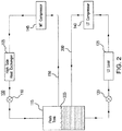
- FIGURE 2 shows the cooling system of FIGURE 1 configured without a medium temperature load.
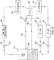
- FIGURE 3 shows the cooling system of FIGURE 1 with imbalanced loads.
- FIGURE 4 describes the operation of the system of FIGURES 2 and 3 .
- system 100 includes a high side heat exchanger 105, an expansion valve 110, a flash tank 115, an expansion valve 120, a low temperature load 125, expansion valve 130, a medium temperature load 135, a low temperature compressor 140, a medium temperature compressor 145, and a flash gas bypass line 150.
- System 100 may circulate a refrigerant to remove heat from spaces proximate low temperature load 125 and medium temperature load 135.
- High side heat exchanger 105 may remove heat from the refrigerant. When heat is removed from the refrigerant, the refrigerant is cooled. This disclosure contemplates high side heat exchanger 105 being operated as a condenser and/or a gas cooler. When operating as a condenser, high side heat exchanger 105 cools the refrigerant such that the state of the refrigerant changes from a gas to a liquid. When operating as a gas cooler, high side heat exchanger 105 cools the refrigerant but the refrigerant remains a gas. In certain configurations, high side heat exchanger 105 is positioned such that heat removed from the refrigerant may be discharged into the air.
- high side heat exchanger 105 may be positioned on a rooftop so that heat removed from the refrigerant may be discharged into the air.
- high side heat exchanger 105 may be positioned external to a building and/or on the side of a building.
- Expansion valves 110, 120, and 130 reduce the pressure and therefore the temperature of the refrigerant. Expansion valves 110, 120, and 130 reduce pressure from the refrigerant flowing into the expansion valves 110, 120, and 130. The temperature of the refrigerant may then drop as pressure is reduced. As a result, warm or hot refrigerant entering expansion valves 110, 120, and 130 may be cooler when leaving expansion valves 110, 120, and 130. The refrigerant leaving expansion valve 110 is fed into flash tank 115. Expansion valves 120 and 130 feed low temperature load 125 and medium temperature load 135 respectively.
- Flash tank 115 may store refrigerant received from high side heat exchanger 105 through expansion valve 110. This disclosure contemplates flash tank 115 storing refrigerant in any state such as, for example, a liquid state and/or a gaseous state. Refrigerant leaving flash tank 115 is fed to low temperature load 125 and medium temperature load 135 through expansion valves 120 and 130. Flash tank 115 is referred to as a receiving vessel in certain embodiments.
- System 100 may include a low temperature portion and a medium temperature portion.
- the low temperature portion may operate at a lower temperature than the medium temperature portion.
- the low temperature portion may be a freezer system and the medium temperature system may be a regular refrigeration system.
- the low temperature portion may include freezers used to hold frozen foods and the medium temperature portion may include refrigerated shelves used to hold produce.
- Refrigerant may flow from flash tank 115 to both the low temperature and medium temperature portions of the refrigeration system.
- the refrigerant may flow to low temperature load 125 and medium temperature load 135.
- the refrigerant removes heat from the air around low temperature load 125 or medium temperature load 135. As a result, the air is cooled.
- the cooled air may then be circulated such as, for example, by a fan to cool a space such as, for example, a freezer and/or a refrigerated shelf.
- a fan to cool a space
- refrigerant may change from a liquid state to a gaseous state.
- Refrigerant may flow from low temperature load 125 and medium temperature load 135 to compressors 140 and 145.
- This disclosure contemplates system 100 including any number of low temperature compressors 140 and medium temperature compressors 145. Both the low temperature compressor 140 and medium temperature compressor 145 may be configured to increase the pressure of the refrigerant. As a result, the heat in the refrigerant may become concentrated and the refrigerant may become a high pressure gas.
- Low temperature compressor 140 may compress refrigerant from low temperature load 125 and send the compressed refrigerant to medium temperature compressor 145.
- Medium temperature compressor 145 may compress refrigerant from low temperature compressor 140 and medium temperature load 135. Medium temperature compressor 145 may then send the compressed refrigerant to high side heat exchanger 105.
- Medium temperature compressor 145 may not be able to safely compress the refrigerant if the temperature of that refrigerant is too high.
- the refrigerant from low temperature compressor 140 may be mixed with a cooler refrigerant coming from medium temperature load 135 before being received by medium temperature compressor 145.
- the refrigerant from low temperature compressor 140 may further be mixed with a cooler flash gas from flash tank 115 via flash gas bypass line 150.
- Flash gas bypass line 150 may be used to mix flash gas from flash tank 115 with the refrigerant from low temperature compressor 140 and medium temperature load 135 before that refrigerant is received by medium temperature compressor 145.
- the flash gas supplied by flash gas bypass line 150 cools the refrigerant before the refrigerant is received by medium temperature compressor 145.
- Flash gas bypass line 150 includes expansion valve 155. Expansion valve 155 may further cool the flash gas coming from flash tank 115.
- the refrigerant from low temperature compressor 140 (125° F-140° F) is cooled by both the refrigerant from medium temperature load 135 (25° F-35° F) and the refrigerant from flash gas line 150 (21° F) at a ratio of about 10%-15% from low temperature load 140, 45%-50% from medium temperature load 135, and 30%-40% from flash gas bypass line 150. This allows medium temperature compressor 145 to operate safely.
- system 100 as illustrated in FIGURE 1 may depend on medium temperature load 135 providing enough refrigerant to mix with the refrigerant from low temperature compressor 140. If medium temperature load 135 is not present or is not providing enough refrigerant, then the refrigerant received by medium temperature compressor 145 may be too high a temperature for medium temperature compressor 145 to safely compress.
- This disclosure contemplates configurations of system 100 that may allow medium temperature compressor 145 to safely compress a received refrigerant when medium temperature load 135 is not present and/or is not providing enough refrigerant.
- FIGURES 2 and 3 illustrate the alternative configurations.
- FIGURE 4 describes the operation of the alternative configurations.
- FIGURE 2 illustrates the example cooling system 100 of FIGURE 1 with the medium temperature load removed.
- system 100 may be configured with a refrigerant routing line 200 when the medium temperature load is removed.
- the refrigerant received by medium temperature compressor 145 may be too hot for medium temperature compressor 145 to safely compress.
- the refrigerant from low temperature compressor 140 is not mixed with the refrigerant from the medium temperature load.
- the resulting mixture (at around 71° F) may include about 60% of high temperature gas from the low temperature compressor 140 at around 140° F and about 40% of the vapor from the flash tank through flash gas bypass line 150 at around 21° F. Because medium temperature compressor 145 may not safely handle refrigerant above 65° F, this mixture may be unsafe to pass to medium temperature compressor 145.
- Refrigerant routing line 200 allows for the refrigerant from low temperature compressor 140 to be further cooled so that medium temperature compressor 145 can safely compress the refrigerant.
- Refrigerant routing line 200 is coupled to low temperature compressor 140 and flash tank 115.
- Refrigerant routing line 200 routes refrigerant from low temperature compressor 140 to flash tank 115.
- the refrigerant is routed to a portion of flash tank 115 that is below a liquid level line 205 of flash tank 115. Because the refrigerant routed by refrigerant routing line 200 is typically in the gaseous state, the refrigerant will rise through the liquid refrigerant in flash tank 115. As the refrigerant travels through the liquid refrigerant, the refrigerant is cooled although the refrigerant may remain in the gaseous state.
- the refrigerant may further mix with the flash gas inside flash tank 115 and/or flash gas bypass line 150, which further cools the refrigerant. After being cooled, the refrigerant may enter flash gas bypass line 150 and travel to medium temperature compressor 145. By routing the refrigerant through flash tank 115, the refrigerant may be cooled sufficiently for medium temperature compressor 145 to safely compress the refrigerant. In this manner, the refrigerant may be sufficiently cooled even though it is not mixed with refrigerant from a medium temperature load.
- flash gas bypass valve 155 is removed from system 100. It is understood however that system 100 may still operate as intended even with flash gas bypass valve 155 included.
- FIGURE 3 illustrates the example cooling system 100 of FIGURE 1 with imbalanced loads.
- medium temperature load 135 may not provide enough refrigerant to mix with the refrigerant from low temperature compressor 140.
- the refrigerant received by medium temperature compressor 145 may be too hot to be safely compressed.
- system 100 can be configured according to the same guiding principles used in the configuration of FIGURE 2 to cool the refrigerant received by medium temperature compressor 145.
- Refrigerant routing line 200 routes the refrigerant from low temperature compressor 140 to flash tank 115 below a liquid level line 205 of flash tank 115.
- the refrigerant is then cooled by the refrigerant in flash tank 115 and leaves flash tank 115 through flash gas bypass line 150. Furthermore, the refrigerant from medium temperature load 135 is mixed with the refrigerant in flash gas bypass line 150 before the refrigerant is received by medium temperature compressor 145. As a result, the refrigerant received by medium temperature compressor 145 is at a low enough temperature such that medium temperature compressor 145 can safely compress the refrigerant. In this manner, system 100 may operate safely even if medium temperature load 135 and low temperature load 125 are imbalanced.
- system 100 includes a heat exchanger 300 coupled to flash gas bypass line 150 and refrigerant routing line 200.
- the heat exchanger transfers heat from the refrigerant in refrigerant routing line 200 to the refrigerant in flash gas bypass line 150.
- the temperature of the refrigerant received by medium temperature compressor 145 may be further regulated to be above a minimum temperature.
- the heat exchanger may offset any over cooling resulting from routing the refrigerant through flash tank 115 and/or flash gas bypass valve 155.
- any liquid refrigerant may be evaporated before reaching medium temperature compressor 145 so that medium temperature compressor 145 does not malfunction.
- system 100 may include a second high side heat exchanger that removes heat from the refrigerant.
- the second high side heat exchanger is positioned along refrigerant routing line 200 between low temperature compressor 140 and flash tank 115.
- the second high side heat exchanger may operate as a gas cooler or as a condenser.
- the second high side heat exchanger may receive refrigerant from low temperature compressor 140, remove heat from that refrigerant, and then send the refrigerant to flash tank 115. In this manner, additional heat may be removed from the refrigerant before it is received by medium temperature compressor 145.
- a portion of refrigerant routing line 200 may extend into flash tank 115.
- the portion extending into flash tank 115 may include a plurality of pipes.
- the refrigerant may travel through these pipes into the liquid refrigerant in flash tank 115.
- one or more of these pipes may be perforated which allows the gaseous refrigerant to escape through holes in the pipe into the liquid refrigerant in flash tank 115.
- the gaseous refrigerant may then bubble up through the liquid refrigerant into flash gas bypass line 150. Perforating these pipes may increase the bubbling surface area, which improves heat removal from the refrigerant.
- refrigerant routing line 200 and flash tank 115 being configured in any appropriate manner.
- a baffle may be positioned between refrigerant routing line 200 and flash gas bypass line 150.
- the baffle may be positioned at the entrance of flash gash bypass line 150. The baffle may restrain the flow of gaseous refrigerant from refrigerant routing line 200 to flash gas bypass line 150. In this manner, the gaseous refrigerant may spend more time in flash tank 115 thereby further reducing the temperature of the gaseous refrigerant.
- FIGURE 4 is a flowchart illustrating a method 400 of operating the example cooling system of FIGURE 2 .
- Various components of the cooling system perform the steps of method 400.
- the temperature of a refrigerant may be reduced before the refrigerant is received by a medium temperature compressor.
- Method 400 may begin by a high side heat exchanger removing heat from a refrigerant in step 405.
- the high side heat exchanger sends the refrigerant to a flash tank.
- the flash tank stores the refrigerant.
- the flash tank sends the refrigerant to a load.
- the load uses the refrigerant to remove heat from a space proximate the load. The load then sends the refrigerant to a first compressor.
- the first compressor compresses the refrigerant.
- the first compressor sends the compressed refrigerant to a refrigerant routing line.
- the refrigerant routing line routes the refrigerant to the flash tank below a liquid level line of the flash tank. In this manner, the refrigerant may be cooled by the liquid refrigerant in the flash tank. After being cooled the refrigerant leaves the flash tank through a flash gas bypass line.
- the flash gas bypass line sends the refrigerant as a flash gas to a second compressor.
- the second compressor compresses the refrigerant in step 435.
- the second compressor sends the refrigerant back to the high side heat exchanger.
- Method 400 may include more, fewer, or other steps. For example, steps may be performed in parallel or in any suitable order. While discussed as various components of cooling system 100 performing the steps, any suitable component or combination of components of system 100 may perform one or more steps of the method.
Applications Claiming Priority (1)
| Application Number | Priority Date | Filing Date | Title |
|---|---|---|---|
| US15/000,817 US9964339B2 (en) | 2016-01-19 | 2016-01-19 | Cooling system with low temperature load |
Publications (2)
| Publication Number | Publication Date |
|---|---|
| EP3196568A1 true EP3196568A1 (fr) | 2017-07-26 |
| EP3196568B1 EP3196568B1 (fr) | 2022-12-07 |
Family
ID=57860687
Family Applications (1)
| Application Number | Title | Priority Date | Filing Date |
|---|---|---|---|
| EP17151860.8A Active EP3196568B1 (fr) | 2016-01-19 | 2017-01-17 | Système de refroidissement à faible charge de température |
Country Status (4)
| Country | Link |
|---|---|
| US (1) | US9964339B2 (fr) |
| EP (1) | EP3196568B1 (fr) |
| CN (1) | CN106989532B (fr) |
| CA (1) | CA2955130C (fr) |
Cited By (5)
| Publication number | Priority date | Publication date | Assignee | Title |
|---|---|---|---|---|
| EP3486579A1 (fr) * | 2017-11-21 | 2019-05-22 | Heatcraft Refrigeration Products LLC | Système de refroidissement |
| EP3584513A1 (fr) * | 2018-06-06 | 2019-12-25 | Heatcraft Refrigeration Products LLC | Système de refroidissement |
| EP3584519A1 (fr) * | 2018-06-05 | 2019-12-25 | Heatcraft Refrigeration Products LLC | Système de refroidissement |
| FR3101698A1 (fr) * | 2019-10-08 | 2021-04-09 | Valeo Systemes Thermiques | Circuit de gestion thermique d’un véhicule automobile électrique ou hybride |
| EP3845828A1 (fr) * | 2020-01-03 | 2021-07-07 | Heatcraft Refrigeration Products LLC | Système de refroidissement à compression parallèle utilisant des compresseurs à température moyenne |
Families Citing this family (20)
| Publication number | Priority date | Publication date | Assignee | Title |
|---|---|---|---|---|
| US10352604B2 (en) * | 2016-12-06 | 2019-07-16 | Heatcraft Refrigeration Products Llc | System for controlling a refrigeration system with a parallel compressor |
| JP6798441B2 (ja) * | 2017-07-31 | 2020-12-09 | 株式会社デンソー | 冷凍サイクル装置 |
| US10365023B2 (en) | 2017-09-06 | 2019-07-30 | Heatcraft Refrigeration Products Llc | Refrigeration system with integrated air conditioning by parallel solenoid valves and check valve |
| MX2020004340A (es) * | 2017-10-24 | 2020-10-14 | Hussmann Corp | Sistema de refrigeracion y metodo de control de carga de refrigeracion. |
| US11118817B2 (en) * | 2018-04-03 | 2021-09-14 | Heatcraft Refrigeration Products Llc | Cooling system |
| US11835270B1 (en) * | 2018-06-22 | 2023-12-05 | Booz Allen Hamilton Inc. | Thermal management systems |
| US11536494B1 (en) | 2018-11-01 | 2022-12-27 | Booz Allen Hamilton Inc. | Thermal management systems for extended operation |
| US11448434B1 (en) | 2018-11-01 | 2022-09-20 | Booz Allen Hamilton Inc. | Thermal management systems |
| US11408649B1 (en) | 2018-11-01 | 2022-08-09 | Booz Allen Hamilton Inc. | Thermal management systems |
| CN109489289B (zh) * | 2018-11-14 | 2020-02-18 | 珠海格力电器股份有限公司 | 复叠式空气调节系统 |
| US11801731B1 (en) | 2019-03-05 | 2023-10-31 | Booz Allen Hamilton Inc. | Thermal management systems |
| US11473814B2 (en) * | 2019-05-13 | 2022-10-18 | Heatcraft Refrigeration Products Llc | Integrated cooling system with flooded air conditioning heat exchanger |
| KR20200137837A (ko) * | 2019-05-31 | 2020-12-09 | 현대자동차주식회사 | 차량용 기액 분리장치 |
| US11796230B1 (en) | 2019-06-18 | 2023-10-24 | Booz Allen Hamilton Inc. | Thermal management systems |
| US11752837B1 (en) | 2019-11-15 | 2023-09-12 | Booz Allen Hamilton Inc. | Processing vapor exhausted by thermal management systems |
| US11150001B2 (en) * | 2019-12-17 | 2021-10-19 | Heatcraft Refrigeration Products Llc | Cooling system with compressor bypass |
| US11561030B1 (en) | 2020-06-15 | 2023-01-24 | Booz Allen Hamilton Inc. | Thermal management systems |
| EP4168724A1 (fr) * | 2020-06-23 | 2023-04-26 | Hill Phoenix Inc. | Système de refroidissement comprenant un système de distribution et une unité de refroidissement |
| CN112361634B (zh) * | 2020-12-14 | 2021-10-26 | 珠海格力电器股份有限公司 | 双级压缩制冷系统、制冷控制方法及制冷设备 |
| CN113091339A (zh) * | 2021-03-29 | 2021-07-09 | 广东美芝制冷设备有限公司 | 双温制冷系统 |
Citations (6)
| Publication number | Priority date | Publication date | Assignee | Title |
|---|---|---|---|---|
| JP2000337722A (ja) * | 1999-05-26 | 2000-12-08 | Sanden Corp | 蒸気圧縮式冷凍サイクル |
| EP1707901A2 (fr) * | 2005-03-30 | 2006-10-04 | Sanyo Electric Co., Ltd. | Dispositif frigorifique et réfrigérateur |
| WO2008140454A1 (fr) * | 2007-05-14 | 2008-11-20 | Carrier Corporation | Système à compression à vapeur de réfrigérant ayant un économiseur à ballon de détente |
| US20090025405A1 (en) * | 2007-07-27 | 2009-01-29 | Johnson Controls Technology Company | Economized Vapor Compression Circuit |
| WO2009152593A1 (fr) * | 2008-06-18 | 2009-12-23 | Whirlpool S.A. | Système de réfrigération |
| EP2317251A1 (fr) * | 2008-08-27 | 2011-05-04 | Mayekawa Mfg. Co., Ltd. | Appareil de cycle pour pompe a chaleur avec compresseur a deux etages |
-
2016
- 2016-01-19 US US15/000,817 patent/US9964339B2/en active Active
-
2017
- 2017-01-17 EP EP17151860.8A patent/EP3196568B1/fr active Active
- 2017-01-17 CA CA2955130A patent/CA2955130C/fr active Active
- 2017-01-19 CN CN201710199521.8A patent/CN106989532B/zh active Active
Patent Citations (6)
| Publication number | Priority date | Publication date | Assignee | Title |
|---|---|---|---|---|
| JP2000337722A (ja) * | 1999-05-26 | 2000-12-08 | Sanden Corp | 蒸気圧縮式冷凍サイクル |
| EP1707901A2 (fr) * | 2005-03-30 | 2006-10-04 | Sanyo Electric Co., Ltd. | Dispositif frigorifique et réfrigérateur |
| WO2008140454A1 (fr) * | 2007-05-14 | 2008-11-20 | Carrier Corporation | Système à compression à vapeur de réfrigérant ayant un économiseur à ballon de détente |
| US20090025405A1 (en) * | 2007-07-27 | 2009-01-29 | Johnson Controls Technology Company | Economized Vapor Compression Circuit |
| WO2009152593A1 (fr) * | 2008-06-18 | 2009-12-23 | Whirlpool S.A. | Système de réfrigération |
| EP2317251A1 (fr) * | 2008-08-27 | 2011-05-04 | Mayekawa Mfg. Co., Ltd. | Appareil de cycle pour pompe a chaleur avec compresseur a deux etages |
Cited By (10)
| Publication number | Priority date | Publication date | Assignee | Title |
|---|---|---|---|---|
| EP3486579A1 (fr) * | 2017-11-21 | 2019-05-22 | Heatcraft Refrigeration Products LLC | Système de refroidissement |
| US10767911B2 (en) | 2017-11-21 | 2020-09-08 | Heatcraft Refrigeration Products Llc | Cooling system |
| EP3584519A1 (fr) * | 2018-06-05 | 2019-12-25 | Heatcraft Refrigeration Products LLC | Système de refroidissement |
| US10663196B2 (en) | 2018-06-05 | 2020-05-26 | Heatcraft Refrigeration Products Llc | Cooling system |
| EP3584513A1 (fr) * | 2018-06-06 | 2019-12-25 | Heatcraft Refrigeration Products LLC | Système de refroidissement |
| US10808975B2 (en) | 2018-06-06 | 2020-10-20 | Heatcraft Refrigeration Products Llc | Cooling system |
| FR3101698A1 (fr) * | 2019-10-08 | 2021-04-09 | Valeo Systemes Thermiques | Circuit de gestion thermique d’un véhicule automobile électrique ou hybride |
| WO2021069831A1 (fr) * | 2019-10-08 | 2021-04-15 | Valeo Systemes Thermiques | Circuit de gestion thermique d'un véhicule automobile électrique ou hybride |
| EP3845828A1 (fr) * | 2020-01-03 | 2021-07-07 | Heatcraft Refrigeration Products LLC | Système de refroidissement à compression parallèle utilisant des compresseurs à température moyenne |
| US11353245B2 (en) | 2020-01-03 | 2022-06-07 | Heatcraft Refrigeration Products Llc | Cooling system with parallel compression using medium temperature compressors |
Also Published As
| Publication number | Publication date |
|---|---|
| US9964339B2 (en) | 2018-05-08 |
| EP3196568B1 (fr) | 2022-12-07 |
| US20170205120A1 (en) | 2017-07-20 |
| CN106989532B (zh) | 2020-02-14 |
| CA2955130C (fr) | 2019-09-17 |
| CN106989532A (zh) | 2017-07-28 |
| CA2955130A1 (fr) | 2017-07-19 |
Similar Documents
| Publication | Publication Date | Title |
|---|---|---|
| CA2955130C (fr) | Systeme de refroidissement a charge basse temperature | |
| EP3550222B1 (fr) | Système de refroidissement | |
| JP2009525453A (ja) | 冷却システム | |
| US11009266B2 (en) | Integrated refrigeration and air conditioning system | |
| CN212386270U (zh) | 大空间的交通工具 | |
| EP3438566B1 (fr) | Stockage thermique de système de dioxyde de carbone pour coupure de courant | |
| EP3370016B1 (fr) | Système de refroidissement à compression parallèle | |
| CA2961945C (fr) | Systeme de refroidissement a sous-refroidissement integre | |
| EP3584519B1 (fr) | Système de refroidissement | |
| EP3486579A1 (fr) | Système de refroidissement | |
| CN111536708A (zh) | 冷却系统 | |
| US20200256602A1 (en) | Cooling system | |
| EP3839377A1 (fr) | Système de réfrigération avec évaporateur partiellement noyé | |
| US10712052B2 (en) | Cooling system with improved compressor stability | |
| JP2015155776A (ja) | 冷却システム |
Legal Events
| Date | Code | Title | Description |
|---|---|---|---|
| PUAI | Public reference made under article 153(3) epc to a published international application that has entered the european phase |
Free format text: ORIGINAL CODE: 0009012 |
|
| STAA | Information on the status of an ep patent application or granted ep patent |
Free format text: STATUS: THE APPLICATION HAS BEEN PUBLISHED |
|
| AK | Designated contracting states |
Kind code of ref document: A1 Designated state(s): AL AT BE BG CH CY CZ DE DK EE ES FI FR GB GR HR HU IE IS IT LI LT LU LV MC MK MT NL NO PL PT RO RS SE SI SK SM TR |
|
| AX | Request for extension of the european patent |
Extension state: BA ME |
|
| STAA | Information on the status of an ep patent application or granted ep patent |
Free format text: STATUS: REQUEST FOR EXAMINATION WAS MADE |
|
| 17P | Request for examination filed |
Effective date: 20180117 |
|
| RBV | Designated contracting states (corrected) |
Designated state(s): AL AT BE BG CH CY CZ DE DK EE ES FI FR GB GR HR HU IE IS IT LI LT LU LV MC MK MT NL NO PL PT RO RS SE SI SK SM TR |
|
| STAA | Information on the status of an ep patent application or granted ep patent |
Free format text: STATUS: EXAMINATION IS IN PROGRESS |
|
| 17Q | First examination report despatched |
Effective date: 20210519 |
|
| STAA | Information on the status of an ep patent application or granted ep patent |
Free format text: STATUS: EXAMINATION IS IN PROGRESS |
|
| GRAP | Despatch of communication of intention to grant a patent |
Free format text: ORIGINAL CODE: EPIDOSNIGR1 |
|
| STAA | Information on the status of an ep patent application or granted ep patent |
Free format text: STATUS: GRANT OF PATENT IS INTENDED |
|
| RIC1 | Information provided on ipc code assigned before grant |
Ipc: F25B 9/00 20060101ALI20220712BHEP Ipc: F25B 40/00 20060101ALI20220712BHEP Ipc: F25B 5/02 20060101ALI20220712BHEP Ipc: F25B 1/10 20060101AFI20220712BHEP |
|
| INTG | Intention to grant announced |
Effective date: 20220805 |
|
| GRAS | Grant fee paid |
Free format text: ORIGINAL CODE: EPIDOSNIGR3 |
|
| GRAA | (expected) grant |
Free format text: ORIGINAL CODE: 0009210 |
|
| STAA | Information on the status of an ep patent application or granted ep patent |
Free format text: STATUS: THE PATENT HAS BEEN GRANTED |
|
| AK | Designated contracting states |
Kind code of ref document: B1 Designated state(s): AL AT BE BG CH CY CZ DE DK EE ES FI FR GB GR HR HU IE IS IT LI LT LU LV MC MK MT NL NO PL PT RO RS SE SI SK SM TR |
|
| REG | Reference to a national code |
Ref country code: GB Ref legal event code: FG4D |
|
| REG | Reference to a national code |
Ref country code: CH Ref legal event code: EP Ref country code: AT Ref legal event code: REF Ref document number: 1536530 Country of ref document: AT Kind code of ref document: T Effective date: 20221215 |
|
| REG | Reference to a national code |
Ref country code: DE Ref legal event code: R096 Ref document number: 602017064309 Country of ref document: DE |
|
| REG | Reference to a national code |
Ref country code: IE Ref legal event code: FG4D |
|
| REG | Reference to a national code |
Ref country code: LT Ref legal event code: MG9D |
|
| REG | Reference to a national code |
Ref country code: NL Ref legal event code: MP Effective date: 20221207 |
|
| PG25 | Lapsed in a contracting state [announced via postgrant information from national office to epo] |
Ref country code: SE Free format text: LAPSE BECAUSE OF FAILURE TO SUBMIT A TRANSLATION OF THE DESCRIPTION OR TO PAY THE FEE WITHIN THE PRESCRIBED TIME-LIMIT Effective date: 20221207 Ref country code: NO Free format text: LAPSE BECAUSE OF FAILURE TO SUBMIT A TRANSLATION OF THE DESCRIPTION OR TO PAY THE FEE WITHIN THE PRESCRIBED TIME-LIMIT Effective date: 20230307 Ref country code: LT Free format text: LAPSE BECAUSE OF FAILURE TO SUBMIT A TRANSLATION OF THE DESCRIPTION OR TO PAY THE FEE WITHIN THE PRESCRIBED TIME-LIMIT Effective date: 20221207 Ref country code: FI Free format text: LAPSE BECAUSE OF FAILURE TO SUBMIT A TRANSLATION OF THE DESCRIPTION OR TO PAY THE FEE WITHIN THE PRESCRIBED TIME-LIMIT Effective date: 20221207 Ref country code: ES Free format text: LAPSE BECAUSE OF FAILURE TO SUBMIT A TRANSLATION OF THE DESCRIPTION OR TO PAY THE FEE WITHIN THE PRESCRIBED TIME-LIMIT Effective date: 20221207 |
|
| PGFP | Annual fee paid to national office [announced via postgrant information from national office to epo] |
Ref country code: FR Payment date: 20230125 Year of fee payment: 7 |
|
| REG | Reference to a national code |
Ref country code: AT Ref legal event code: MK05 Ref document number: 1536530 Country of ref document: AT Kind code of ref document: T Effective date: 20221207 |
|
| PG25 | Lapsed in a contracting state [announced via postgrant information from national office to epo] |
Ref country code: RS Free format text: LAPSE BECAUSE OF FAILURE TO SUBMIT A TRANSLATION OF THE DESCRIPTION OR TO PAY THE FEE WITHIN THE PRESCRIBED TIME-LIMIT Effective date: 20221207 Ref country code: PL Free format text: LAPSE BECAUSE OF FAILURE TO SUBMIT A TRANSLATION OF THE DESCRIPTION OR TO PAY THE FEE WITHIN THE PRESCRIBED TIME-LIMIT Effective date: 20221207 Ref country code: LV Free format text: LAPSE BECAUSE OF FAILURE TO SUBMIT A TRANSLATION OF THE DESCRIPTION OR TO PAY THE FEE WITHIN THE PRESCRIBED TIME-LIMIT Effective date: 20221207 Ref country code: HR Free format text: LAPSE BECAUSE OF FAILURE TO SUBMIT A TRANSLATION OF THE DESCRIPTION OR TO PAY THE FEE WITHIN THE PRESCRIBED TIME-LIMIT Effective date: 20221207 Ref country code: GR Free format text: LAPSE BECAUSE OF FAILURE TO SUBMIT A TRANSLATION OF THE DESCRIPTION OR TO PAY THE FEE WITHIN THE PRESCRIBED TIME-LIMIT Effective date: 20230308 |
|
| PGFP | Annual fee paid to national office [announced via postgrant information from national office to epo] |
Ref country code: GB Payment date: 20230127 Year of fee payment: 7 Ref country code: DE Payment date: 20230127 Year of fee payment: 7 |
|
| P01 | Opt-out of the competence of the unified patent court (upc) registered |
Effective date: 20230514 |
|
| PG25 | Lapsed in a contracting state [announced via postgrant information from national office to epo] |
Ref country code: NL Free format text: LAPSE BECAUSE OF FAILURE TO SUBMIT A TRANSLATION OF THE DESCRIPTION OR TO PAY THE FEE WITHIN THE PRESCRIBED TIME-LIMIT Effective date: 20221207 |
|
| PG25 | Lapsed in a contracting state [announced via postgrant information from national office to epo] |
Ref country code: SM Free format text: LAPSE BECAUSE OF FAILURE TO SUBMIT A TRANSLATION OF THE DESCRIPTION OR TO PAY THE FEE WITHIN THE PRESCRIBED TIME-LIMIT Effective date: 20221207 Ref country code: RO Free format text: LAPSE BECAUSE OF FAILURE TO SUBMIT A TRANSLATION OF THE DESCRIPTION OR TO PAY THE FEE WITHIN THE PRESCRIBED TIME-LIMIT Effective date: 20221207 Ref country code: PT Free format text: LAPSE BECAUSE OF FAILURE TO SUBMIT A TRANSLATION OF THE DESCRIPTION OR TO PAY THE FEE WITHIN THE PRESCRIBED TIME-LIMIT Effective date: 20230410 Ref country code: EE Free format text: LAPSE BECAUSE OF FAILURE TO SUBMIT A TRANSLATION OF THE DESCRIPTION OR TO PAY THE FEE WITHIN THE PRESCRIBED TIME-LIMIT Effective date: 20221207 Ref country code: CZ Free format text: LAPSE BECAUSE OF FAILURE TO SUBMIT A TRANSLATION OF THE DESCRIPTION OR TO PAY THE FEE WITHIN THE PRESCRIBED TIME-LIMIT Effective date: 20221207 Ref country code: AT Free format text: LAPSE BECAUSE OF FAILURE TO SUBMIT A TRANSLATION OF THE DESCRIPTION OR TO PAY THE FEE WITHIN THE PRESCRIBED TIME-LIMIT Effective date: 20221207 |
|
| PG25 | Lapsed in a contracting state [announced via postgrant information from national office to epo] |
Ref country code: SK Free format text: LAPSE BECAUSE OF FAILURE TO SUBMIT A TRANSLATION OF THE DESCRIPTION OR TO PAY THE FEE WITHIN THE PRESCRIBED TIME-LIMIT Effective date: 20221207 Ref country code: IS Free format text: LAPSE BECAUSE OF FAILURE TO SUBMIT A TRANSLATION OF THE DESCRIPTION OR TO PAY THE FEE WITHIN THE PRESCRIBED TIME-LIMIT Effective date: 20230407 Ref country code: AL Free format text: LAPSE BECAUSE OF FAILURE TO SUBMIT A TRANSLATION OF THE DESCRIPTION OR TO PAY THE FEE WITHIN THE PRESCRIBED TIME-LIMIT Effective date: 20221207 |
|
| REG | Reference to a national code |
Ref country code: CH Ref legal event code: PL |
|
| REG | Reference to a national code |
Ref country code: DE Ref legal event code: R097 Ref document number: 602017064309 Country of ref document: DE |
|
| PG25 | Lapsed in a contracting state [announced via postgrant information from national office to epo] |
Ref country code: MC Free format text: LAPSE BECAUSE OF FAILURE TO SUBMIT A TRANSLATION OF THE DESCRIPTION OR TO PAY THE FEE WITHIN THE PRESCRIBED TIME-LIMIT Effective date: 20221207 Ref country code: LU Free format text: LAPSE BECAUSE OF NON-PAYMENT OF DUE FEES Effective date: 20230117 |
|
| REG | Reference to a national code |
Ref country code: BE Ref legal event code: MM Effective date: 20230131 |
|
| PLBE | No opposition filed within time limit |
Free format text: ORIGINAL CODE: 0009261 |
|
| STAA | Information on the status of an ep patent application or granted ep patent |
Free format text: STATUS: NO OPPOSITION FILED WITHIN TIME LIMIT |
|
| PG25 | Lapsed in a contracting state [announced via postgrant information from national office to epo] |
Ref country code: LI Free format text: LAPSE BECAUSE OF NON-PAYMENT OF DUE FEES Effective date: 20230131 Ref country code: DK Free format text: LAPSE BECAUSE OF FAILURE TO SUBMIT A TRANSLATION OF THE DESCRIPTION OR TO PAY THE FEE WITHIN THE PRESCRIBED TIME-LIMIT Effective date: 20221207 Ref country code: CH Free format text: LAPSE BECAUSE OF NON-PAYMENT OF DUE FEES Effective date: 20230131 |
|
| 26N | No opposition filed |
Effective date: 20230908 |
|
| PG25 | Lapsed in a contracting state [announced via postgrant information from national office to epo] |
Ref country code: SI Free format text: LAPSE BECAUSE OF FAILURE TO SUBMIT A TRANSLATION OF THE DESCRIPTION OR TO PAY THE FEE WITHIN THE PRESCRIBED TIME-LIMIT Effective date: 20221207 Ref country code: BE Free format text: LAPSE BECAUSE OF NON-PAYMENT OF DUE FEES Effective date: 20230131 |
|
| PG25 | Lapsed in a contracting state [announced via postgrant information from national office to epo] |
Ref country code: IE Free format text: LAPSE BECAUSE OF NON-PAYMENT OF DUE FEES Effective date: 20230117 |
|
| PGFP | Annual fee paid to national office [announced via postgrant information from national office to epo] |
Ref country code: DE Payment date: 20240129 Year of fee payment: 8 Ref country code: GB Payment date: 20240129 Year of fee payment: 8 |