EP3196381B1 - Lining board and method for manufacturing lining board - Google Patents
Lining board and method for manufacturing lining board Download PDFInfo
- Publication number
- EP3196381B1 EP3196381B1 EP17152247.7A EP17152247A EP3196381B1 EP 3196381 B1 EP3196381 B1 EP 3196381B1 EP 17152247 A EP17152247 A EP 17152247A EP 3196381 B1 EP3196381 B1 EP 3196381B1
- Authority
- EP
- European Patent Office
- Prior art keywords
- lining
- tiles
- tile
- recess
- adhesive mass
- Prior art date
- Legal status (The legal status is an assumption and is not a legal conclusion. Google has not performed a legal analysis and makes no representation as to the accuracy of the status listed.)
- Active
Links
Images

Classifications
-
- E—FIXED CONSTRUCTIONS
- E04—BUILDING
- E04F—FINISHING WORK ON BUILDINGS, e.g. STAIRS, FLOORS
- E04F13/00—Coverings or linings, e.g. for walls or ceilings
- E04F13/07—Coverings or linings, e.g. for walls or ceilings composed of covering or lining elements; Sub-structures therefor; Fastening means therefor
- E04F13/072—Coverings or linings, e.g. for walls or ceilings composed of covering or lining elements; Sub-structures therefor; Fastening means therefor composed of specially adapted, structured or shaped covering or lining elements
- E04F13/076—Coverings or linings, e.g. for walls or ceilings composed of covering or lining elements; Sub-structures therefor; Fastening means therefor composed of specially adapted, structured or shaped covering or lining elements characterised by the joints between neighbouring elements, e.g. with joint fillings or with tongue and groove connections
-
- E—FIXED CONSTRUCTIONS
- E04—BUILDING
- E04F—FINISHING WORK ON BUILDINGS, e.g. STAIRS, FLOORS
- E04F13/00—Coverings or linings, e.g. for walls or ceilings
- E04F13/07—Coverings or linings, e.g. for walls or ceilings composed of covering or lining elements; Sub-structures therefor; Fastening means therefor
- E04F13/08—Coverings or linings, e.g. for walls or ceilings composed of covering or lining elements; Sub-structures therefor; Fastening means therefor composed of a plurality of similar covering or lining elements
- E04F13/0862—Coverings or linings, e.g. for walls or ceilings composed of covering or lining elements; Sub-structures therefor; Fastening means therefor composed of a plurality of similar covering or lining elements composed of a number of elements which are identical or not, e.g. carried by a common web, support plate or grid
-
- B—PERFORMING OPERATIONS; TRANSPORTING
- B28—WORKING CEMENT, CLAY, OR STONE
- B28B—SHAPING CLAY OR OTHER CERAMIC COMPOSITIONS; SHAPING SLAG; SHAPING MIXTURES CONTAINING CEMENTITIOUS MATERIAL, e.g. PLASTER
- B28B23/00—Arrangements specially adapted for the production of shaped articles with elements wholly or partly embedded in the moulding material; Production of reinforced objects
- B28B23/0056—Means for inserting the elements into the mould or supporting them in the mould
-
- B—PERFORMING OPERATIONS; TRANSPORTING
- B28—WORKING CEMENT, CLAY, OR STONE
- B28B—SHAPING CLAY OR OTHER CERAMIC COMPOSITIONS; SHAPING SLAG; SHAPING MIXTURES CONTAINING CEMENTITIOUS MATERIAL, e.g. PLASTER
- B28B23/00—Arrangements specially adapted for the production of shaped articles with elements wholly or partly embedded in the moulding material; Production of reinforced objects
- B28B23/02—Arrangements specially adapted for the production of shaped articles with elements wholly or partly embedded in the moulding material; Production of reinforced objects wherein the elements are reinforcing members
- B28B23/22—Arrangements specially adapted for the production of shaped articles with elements wholly or partly embedded in the moulding material; Production of reinforced objects wherein the elements are reinforcing members assembled from preformed parts
-
- E—FIXED CONSTRUCTIONS
- E04—BUILDING
- E04C—STRUCTURAL ELEMENTS; BUILDING MATERIALS
- E04C2/00—Building elements of relatively thin form for the construction of parts of buildings, e.g. sheet materials, slabs, or panels
- E04C2/02—Building elements of relatively thin form for the construction of parts of buildings, e.g. sheet materials, slabs, or panels characterised by specified materials
- E04C2/04—Building elements of relatively thin form for the construction of parts of buildings, e.g. sheet materials, slabs, or panels characterised by specified materials of concrete or other stone-like material; of asbestos cement; of cement and other mineral fibres
-
- E—FIXED CONSTRUCTIONS
- E04—BUILDING
- E04C—STRUCTURAL ELEMENTS; BUILDING MATERIALS
- E04C2/00—Building elements of relatively thin form for the construction of parts of buildings, e.g. sheet materials, slabs, or panels
- E04C2/02—Building elements of relatively thin form for the construction of parts of buildings, e.g. sheet materials, slabs, or panels characterised by specified materials
- E04C2/26—Building elements of relatively thin form for the construction of parts of buildings, e.g. sheet materials, slabs, or panels characterised by specified materials composed of materials covered by two or more of groups E04C2/04, E04C2/08, E04C2/10 or of materials covered by one of these groups with a material not specified in one of the groups
- E04C2/28—Building elements of relatively thin form for the construction of parts of buildings, e.g. sheet materials, slabs, or panels characterised by specified materials composed of materials covered by two or more of groups E04C2/04, E04C2/08, E04C2/10 or of materials covered by one of these groups with a material not specified in one of the groups combinations of materials fully covered by groups E04C2/04 and E04C2/08
-
- E—FIXED CONSTRUCTIONS
- E04—BUILDING
- E04F—FINISHING WORK ON BUILDINGS, e.g. STAIRS, FLOORS
- E04F13/00—Coverings or linings, e.g. for walls or ceilings
- E04F13/07—Coverings or linings, e.g. for walls or ceilings composed of covering or lining elements; Sub-structures therefor; Fastening means therefor
- E04F13/08—Coverings or linings, e.g. for walls or ceilings composed of covering or lining elements; Sub-structures therefor; Fastening means therefor composed of a plurality of similar covering or lining elements
- E04F13/088—Coverings or linings, e.g. for walls or ceilings composed of covering or lining elements; Sub-structures therefor; Fastening means therefor composed of a plurality of similar covering or lining elements fixed directly to the wall by means of magnets, hook and loop-type or similar fasteners, not necessarily involving the side faces of the covering element
- E04F13/0882—Coverings or linings, e.g. for walls or ceilings composed of covering or lining elements; Sub-structures therefor; Fastening means therefor composed of a plurality of similar covering or lining elements fixed directly to the wall by means of magnets, hook and loop-type or similar fasteners, not necessarily involving the side faces of the covering element by hook and loop-type fasteners
-
- E—FIXED CONSTRUCTIONS
- E04—BUILDING
- E04F—FINISHING WORK ON BUILDINGS, e.g. STAIRS, FLOORS
- E04F13/00—Coverings or linings, e.g. for walls or ceilings
- E04F13/07—Coverings or linings, e.g. for walls or ceilings composed of covering or lining elements; Sub-structures therefor; Fastening means therefor
- E04F13/08—Coverings or linings, e.g. for walls or ceilings composed of covering or lining elements; Sub-structures therefor; Fastening means therefor composed of a plurality of similar covering or lining elements
- E04F13/0889—Coverings or linings, e.g. for walls or ceilings composed of covering or lining elements; Sub-structures therefor; Fastening means therefor composed of a plurality of similar covering or lining elements characterised by the joints between neighbouring elements, e.g. with joint fillings or with tongue and groove connections
- E04F13/0891—Coverings or linings, e.g. for walls or ceilings composed of covering or lining elements; Sub-structures therefor; Fastening means therefor composed of a plurality of similar covering or lining elements characterised by the joints between neighbouring elements, e.g. with joint fillings or with tongue and groove connections with joint fillings
-
- E—FIXED CONSTRUCTIONS
- E04—BUILDING
- E04F—FINISHING WORK ON BUILDINGS, e.g. STAIRS, FLOORS
- E04F13/00—Coverings or linings, e.g. for walls or ceilings
- E04F13/07—Coverings or linings, e.g. for walls or ceilings composed of covering or lining elements; Sub-structures therefor; Fastening means therefor
- E04F13/08—Coverings or linings, e.g. for walls or ceilings composed of covering or lining elements; Sub-structures therefor; Fastening means therefor composed of a plurality of similar covering or lining elements
- E04F13/14—Coverings or linings, e.g. for walls or ceilings composed of covering or lining elements; Sub-structures therefor; Fastening means therefor composed of a plurality of similar covering or lining elements stone or stone-like materials, e.g. ceramics concrete; of glass or with an outer layer of stone or stone-like materials or glass
-
- E—FIXED CONSTRUCTIONS
- E04—BUILDING
- E04F—FINISHING WORK ON BUILDINGS, e.g. STAIRS, FLOORS
- E04F13/00—Coverings or linings, e.g. for walls or ceilings
- E04F13/07—Coverings or linings, e.g. for walls or ceilings composed of covering or lining elements; Sub-structures therefor; Fastening means therefor
- E04F13/08—Coverings or linings, e.g. for walls or ceilings composed of covering or lining elements; Sub-structures therefor; Fastening means therefor composed of a plurality of similar covering or lining elements
- E04F13/16—Coverings or linings, e.g. for walls or ceilings composed of covering or lining elements; Sub-structures therefor; Fastening means therefor composed of a plurality of similar covering or lining elements of fibres or chips, e.g. bonded with synthetic resins, or with an outer layer of fibres or chips
- E04F13/165—Coverings or linings, e.g. for walls or ceilings composed of covering or lining elements; Sub-structures therefor; Fastening means therefor composed of a plurality of similar covering or lining elements of fibres or chips, e.g. bonded with synthetic resins, or with an outer layer of fibres or chips with an outer layer imitating natural stone, brick work, tiled surface or the like
Definitions
- the invention relates to a lining board which comprises lining tiles secured to each other with adhesive mass, the lining tiles having a front surface, back surface, and side surfaces between the front surface and the back surface.
- the invention further relates to a lining tile which comprises a front surface, back surface, and side surfaces between the front surface and back surface.
- the invention further relates to a method for manufacturing a lining board, in which method lining tiles that form the front side of the lining board are placed side by side, said lining tiles comprising a front surface, a back surface and side surfaces between the front surface and the back surface, and the lining tiles are secured to each other with adhesive mass.
- Lining boards provided with lining tiles are used on the external cladding of a building to form the facade of the building.
- a lining board may be secured to a wall of a building with supports mounted in said wall, for example.
- FI publication 117485 discloses a method for manufacturing a front side board for external cladding of a building. In the method in question, the gaps between the lining tiles of the front side board are filled with sealing compound that secures the lining tiles to each other.
- the front side board put forth in said publication further includes a back-plate forming the frame structure of the front side board and having grip spikes that sink in the seams between the tiles and bind the tiling and the back sheet to each other to form a complete front side board.
- Other lining boards are disclosed in US-publications 3234692 A which teaches the features of the preamble of the independent claims and 2004/065035 A1 .
- An object of the invention is to provide a novel lining board.
- the lining tiles are fixed to one another by means of adhesive mass fed to one or more recesses formed in one or more side surfaces of the lining tiles.
- adhesive mass fed to one or more recesses formed in one or more side surfaces of the lining tiles.
- adjacent lining tiles may be installed very close to each other, whereby a lining board is created in which the distance between adjacent lining tiles may be set to be very small, but in which the securing of the lining tiles to each other is still firm, preventing, for example, the bending of individual lining tiles as a result of temperature variations. If the side edges of the lining tiles are perfectly straight, the lining tiles may even be installed directly on top of each other or the ends in a butt joint with respect to each other, whereby there is not necessarily any kind of gap between the lining tiles.
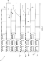
- Figure 1 is a schematic front view showing a lining board 1.
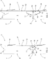
- Figure 2 is a schematic side view of a part of a cross section of an embodiment of a lining board 1 according to Figure 1 .
- Figure 2 does not show the cross section lines of the various parts of the lining board 1.
- the lining board 1 has a front side 1' oriented outward, that is, to be visible, and a back side 1" oriented inward, that is, invisible, when the lining board 1 is installed in place.
- the lining board 1 comprises lining tiles 3 placed side by side at a distance from each other, determined by the width of a gap 2.
- the lining tile 3 has a front surface 4 oriented outward so as to be visible, that is, in the direction of the front side 1' of the lining board 1, and a back surface 5 oriented inward so as to be invisible, that is, in the direction of the back side 1" of the lining board 1.
- the lining tile 3 shown in Figures 1 , 2 is a rectangle in shape and has a first side surface 6, a second side surface 7, a third side surface 8, and a fourth side surface 9 between the front surface 4 and back surface 5.
- the first side surface 6 and the second side surface 7 are additionally side surfaces oriented substantially in opposite directions in relation to each other, so side surfaces oriented away from each other, as are the third side surface 8 and the fourth side surface 9 side surfaces oriented substantially in opposite directions in relation to each other, so side surfaces oriented away from each other.
- the first side surface 6 forms the upward top surface or top edge of the lining tile 3
- the second side surface 7 forms the downward lower surface or lower edge of the lining tile 3
- the third side surface 8 and the fourth side surface 9 form the end surfaces or end edges of the lining tile 3.
- the installation position of the lining tile 3 may also differ from the ones shown in the drawings, that is, the lining tile 3 may also be installed in a vertical or slanting position.
- the external appearance of a lining tile may also differ from the rectangle shape described.
- a lining tile may therefore also be, for example, triangular or a polygon other than a square, in other words, an angular lining tile may have three or more angles, and the number of the side surfaces of a lining tile varies according to the shape in question.
- the lining tile 3 of Figure 2 like lining tiles 3 shown in Figure 3 , 4, 5, and 6 below, comprises a recess 10 in the first side surface 6 parallel to the side surface 6, in other words, in the longitudinal direction of the side surface 6, which is oriented from the first side surface 6 inward into the lining tile 3, said recess 10 being open outward from the first side surface 6.
- the recess 10 is formed by removing material from the first side surface 6 or by omitting material from the first side surface 6 so that the first side surface 6 is not substantially evenly continuous on the entire thickness of the lining tile 3, that is, on the distance between the front surface 4 and back surface 5 of the lining tile 3.
- the second side surface 7 of the lining tile 3, in other words, the side surface 7 oriented substantially in the opposite direction in relation to side surface 6, has a recess 11 parallel to the side surface 7, that is, in the longitudinal direction of the side surface 7, which is oriented inward from the second side surface 7 into the lining tile 3, said recess 11 being open outward from the second side surface 7.
- the recess 11 may be formed in the same manner as the recess 10 in the first side surface 6.
- said recesses 10, 11 are adapted to extend all the way to the back surface 5 of the lining tile 3.
- the dimension of the back surface 5 of the lining tile 3 in the vertical direction of Figure 2 that is, in the direction between the side surfaces 6, 7 comprising the recesses 10, 11 in the lining tile 3 is smaller than the dimension of the front surface 4 of the lining tile 3 in the corresponding direction.
- the recesses 10, 11 are formed in the back surface 5 of the lining tile 3, in the edges 6, 7 of the lining tile, the recesses 10, 11 being adapted to extend towards the front surface 4 of the lining tile 3.
- the lining tiles 3 of the drawings do not show the recesses corresponding to the recesses 10, 11 in the third side surface 8 or the fourth side surface 9 of the lining tile 3, but if so desired similar recesses may also be arranged in them.
- at least one side surface of the lining tile 3 at least one recess is arranged, which is either a recess of the type of the recesses 10, 11 or a recess as described below.
- the dimension of the back surface 5 of the lining tile 3 is smaller in the direction of the side surface of the lining tile 3 that comprises the recess than the dimension of the front surface 4 of the lining tile 3 in the corresponding direction.
- the lining board 1 further includes a back-plate 12, which may be a steel plate, for example.
- the back-plate 12 includes grippers 13, which are protrusions pointing in the direction 1' of the front side of the lining board 1, or in other words, towards the back surface 5 of the lining tile 3.
- Said grippers 13 may be separately fixed to the back-plate 12, but more preferably said grippers 13 are fixed portions of the back-plates 12 and formed of the back-plate 12, for example, by punching said portion with the exception of one edge off the back-plate 12 and by bending it in the shape of a protrusion of the desired shape.
- the back-plate 12 includes hangers 14, which are protrusions oriented in the direction of the back side 1" of the lining board 1, or in other words, oriented away from the back surface 5 of the lining tile 3.
- Said hangers 14 may be separately fixed to the back-plate 12, but more preferably said hangers 14 are fixed portions of the back-plates 12 and formed of the back-plate 12, for example, by punching said portion with the exception of one edge off the back-plate 12 and by bending it in the shape of a protrusion of the desired shape.
- the lining board 1 When the lining board 1 is installed in place on a wall, the lining board 1 is placed by its hangers 14 on the wall to be supported by its supports fixed in the wall.
- Said hangers 14 may have a plurality of obvious implementations known per se to a person skilled in the art, which in this context will not be examined in any greater detail.
- a lining board 1 is manufactured as follows.
- the lining tiles 3 are positioned on a manufacturing platform with their front surfaces 4 facing down, at a distance from each other determined by the desired gap 2.
- a meshy tiling guide for example, may be utilised, having longitudinal and transverse rods that define the mutual positioning of the lining tiles 3.
- the lining tiles 3 may be put in place either by hand or automatically with the aid of a robot, for example.
- the positioning of the lining tiles 3 may be carried out automatically without a special tiling guide by means of a robot, only.
- adhesive mass 16 is fed to the chamber 15 formed by the opposite recesses 10, 11 of the adjacent lining tiles 3, said adhesive mass 16, as it is curing, securing adjacent lining tiles 3 to each other.
- Such an amount of adhesive mass 16 is fed that once is has cured it substantially fills the chamber 15, but does not spread to the back surfaces of the lining tiles 3.
- the back-plate 12 Before the adhesive mass 16 cures, the back-plate 12 is put in place so that the grippers 13 are positioned in the chambers 15 and embed in the adhesive mass 16 fed in said chambers 15. In such a case, the adhesive mass 16, as it is curing, secures the tiling formed by the lining tiles 3 into the back-plate 12 through the adhesive mass 16 and the grippers 13, the back-plate 12 thereby forming the frame structure of the lining board 1.
- micro stone sprinkle 17 is fed in the gaps between the lining tiles 3, which comprises stone chips with a diameter of approximately 2 mm, for example.
- the micro stone sprinkle 17 prevents the adhesive mass from penetrating into the manufacturing platform of the lining board 1 and at the same time provides the bottom of the gap 2 with a tidy appearance.
- the micro stone sprinkle 17 is schematically shown in Figure 3 .
- the lining tiles 3 are secured to each other on the back side of the lining tiles 3 by means of adhesive mass 16 fed into recesses formed in the side surfaces of the lining tiles 3.
- adhesive mass 16 fed into recesses formed in the side surfaces of the lining tiles 3.
- a space that is, a chamber 15 is created between adjacent lining tiles 3, into which a sufficient amount of adhesive mass 16 may be fed to firmly secure adjacent lining tiles 3 to each other, the edges of said recesses forming bonding surfaces in the lining tile 3 for the adhesive mass 16.
- adjacent lining tiles 3 may be installed very close to each other, whereby a lining board is created in which the distance between adjacent lining tiles may be set to be very small, but in which the securing of lining tiles to each other and the possible back-plate forming the back frame of the lining board is still firm, preventing, for example, the bending of individual brick tiles as a result of temperature variations. If the side surfaces of the lining tiles are perfectly straight, the lining tiles may even be installed directly on top of each other or the ends in a butt joint with respect to each other, whereby there is no gap between the lining tiles.
- the recess 10, 11 formed in the side surface of the lining tile 3 may extend on a part of the length of said side surface, only. On the length of the side surface of the lining tile 3 there may be one or more separate local recesses in line with it, the direction of which may also differ from the longitudinal direction of the side surface. One or more or even all of said local recesses may form a chamber 15 for the gripper 13 to bind the tiling formed by the lining tiles 3 to the back-plate.
- the recess 10, 11 is adapted to extend on the entire length of the side surface, whereby the lining tile 3 is most firmly secured in place.
- the cross section of the recesses 10, 11 is rectangular.
- the size of the surface area of the sides of the recesses formed in the lining tile 3 may be affected, that is, the size of the surface area which in the lining tile 3 forms the bonding surfaces for the adhesive mass 16.
- Figures 3 to 6 illustrate alternative embodiments for the cross sections of the recesses 10, 11, but other embodiments for the cross sections of the recesses 10, 11 are also possible. For reasons of clarity, Figures 3 to 6 do not show the cross section lines of the various parts of the lining board 1.
- the side surfaces 6, 7 directed towards each other in the vertically adjacent lining tiles 3 both comprise recesses 10, 11 directed towards each other, in other words in the adherence of the side surfaces directed towards each other in two adjacent lining tiles, the side surfaces of both lining tiles have at least one recess 10, 11, which when positioned substantially opposite each other together form a chamber 15 for the adhesive mass 16.
- the lining tile 3 itself in such a case, has recesses 10, 11 in the side surfaces 6, 7 directed in opposite directions in the lining tiles 3 with respect to each other, whereby each lining tile 3 is firmly secured to the adjacent lining tiles 3 so that individual lining tiles may not bend as a result of temperature variations, for example.
- only one of the side surfaces 6, 7 directed towards each other in the adjacent lining tiles 3 has the recess 10, 11.
- the side surface of only one lining tile 3 has the recess 10 or 11, whereby in said adherence the recess 10, 11 in only one of the lining tiles 3 forms the chamber 15 for the adhesive mass 16, and the binding of the adhesive mass 16 to the lining tile 3 without the recess 10, 11 takes place on the side surface without the recess 10,11 in the lining tile 3 in question.
- the securing in place of the lining tiles 3 does not necessarily always take place as firmly as in the embodiments shown in the drawings.
- an implementation of the lining board 1 is also possible where only some of the lining tiles 3 of the lining board 1 have recesses 10, 11.
- a side surface 6, 7, 8, 9 of the lining tile 3 may comprise in said side surface, on the portion between the front surface 4 and back surface 5, a recess which is directed inward to the lining tile 3 from said side surface 6, said recess being open outward but not extending all the way to the back surface 5 of the lining tile 3.
- An example of such a recess is a groove formed in the side surface of the lining tile 3 in the longitudinal direction of the side surface.
- This embodiment too, has the alternative where only one of the side surfaces positioned opposite each other in the adjacent lining tiles comprises a recess. If such a recess solution is applied, a gap always needs to be left between the lining tiles between the side surfaces where the adhesive mass is fed.
- a lining board 1 does not comprise a back-plate 12, but lining tiles 3 secured to each other with adhesive mass 16, only.
- the lining board 1 may be secured to supports fixed in a building wall with screws drilled through the lining board, or hangers embedded in adhesive mass on the back side of the lining board.
- a lining tile may be a brick sheet, for example.
- the brick sheet may be a burnt brick sheet. Due to the burning process of a burnt brick sheet, the sides or edges of the brick sheet may not necessarily be entirely straight.
- burnt brick sheets are used, the gap between adjacent brick sheets may be from 1 to 6 mm wide, only, which is considerably less than in lining boards imitating typical masonry facings, in which the seam width between adjacent brick sheets is typically from 10 to 13 mm.
- a brick sheet may also be a cut brick sheet.
- the sides or edges of the brick sheet may even be perfectly straight.
- the lining tiles may even be installed directly on top of each other or the ends in a butt joint with respect to each other, whereby there is not necessarily any kind of gap between the lining tiles unless the specific aim is to leave one there.
- a lining tile may be a lining stone tile, for example.
- the sides or edges of a lining stone tile may either have been sawn perfectly straight or their straightness may differ, whereby the lining stone tiles may be installed directly on top of each other or the ends in a butt joint with respect to each other, or a narrow gap may be left between them.
- a lining tile may also be a plastic tile, whereby the sides or edges of the lining tile may be perfectly straight or their straightness may have been made to differ on purpose.
- the front surface of a plastic tile may also be provided with a pattern or profile imitating a brick tile or a lining stone tile.
- a lining tile may also be a clinker tile, whereby the sides or edges of the lining tile may be perfectly straight or their straightness may vary.
- a lining board implemented with brick tiles, lining stone tiles, or clinker tiles may be used as front side lining boards of outer walls of buildings, or as internal lining boards of the indoor walls of a building.
- a lining board implemented with plastic tiles may also be used as the front side lining boards of building outer walls, but due to its light weight it is particularly well suited for use as a lining board of light-weight indoor walls.
- cement-based grout, cement or epoxy based jointing mortars or plastic pastes may be used.
- grout, jointing mortars, or plastic pastes may be used.
- Plastic pastes may be best suited for fastening plastic tiles, but the use of grout or jointing mortar to fasten plastic tiles is also possible.
Landscapes
- Engineering & Computer Science (AREA)
- Architecture (AREA)
- Civil Engineering (AREA)
- Structural Engineering (AREA)
- Chemical & Material Sciences (AREA)
- Ceramic Engineering (AREA)
- Manufacturing & Machinery (AREA)
- Mechanical Engineering (AREA)
- Finishing Walls (AREA)
- Laminated Bodies (AREA)
Description
- The invention relates to a lining board which comprises lining tiles secured to each other with adhesive mass, the lining tiles having a front surface, back surface, and side surfaces between the front surface and the back surface.
- The invention further relates to a lining tile which comprises a front surface, back surface, and side surfaces between the front surface and back surface.
- The invention further relates to a method for manufacturing a lining board, in which method lining tiles that form the front side of the lining board are placed side by side, said lining tiles comprising a front surface, a back surface and side surfaces between the front surface and the back surface, and the lining tiles are secured to each other with adhesive mass.
- Lining boards provided with lining tiles are used on the external cladding of a building to form the facade of the building. A lining board may be secured to a wall of a building with supports mounted in said wall, for example. FI publication 117485 discloses a method for manufacturing a front side board for external cladding of a building. In the method in question, the gaps between the lining tiles of the front side board are filled with sealing compound that secures the lining tiles to each other. The front side board put forth in said publication further includes a back-plate forming the frame structure of the front side board and having grip spikes that sink in the seams between the tiles and bind the tiling and the back sheet to each other to form a complete front side board. Other lining boards are disclosed in
US-publications 3234692 A which teaches the features of the preamble of the independent claims and2004/065035 A1 . - An object of the invention is to provide a novel lining board.
- The invention is characterized by the features of the independent claims.
- In the solution put forth, the lining tiles are fixed to one another by means of adhesive mass fed to one or more recesses formed in one or more side surfaces of the lining tiles. With said recesses, it is possible to establish, on the back surface side of the lining tiles, a space or chamber between adjacent lining tiles, into which an adequate amount of adhesive mass may be fed to fix adjacent lining tiles securely to each other on the back surface side of the lining tiles. Due to the recesses, adjacent lining tiles may be installed very close to each other, whereby a lining board is created in which the distance between adjacent lining tiles may be set to be very small, but in which the securing of the lining tiles to each other is still firm, preventing, for example, the bending of individual lining tiles as a result of temperature variations. If the side edges of the lining tiles are perfectly straight, the lining tiles may even be installed directly on top of each other or the ends in a butt joint with respect to each other, whereby there is not necessarily any kind of gap between the lining tiles.
- The invention is now described in closer detail in connection with preferred embodiments and with reference to the accompanying drawings, in which
-
Figure 1 is a schematic front view of a lining board, -
Figure 2 shows schematically a side view of a part of a cross section of an embodiment of a lining board according toFigure 1 , -
Figure 3 shows schematically a side view of a part of a cross section of another embodiment of a lining board according toFigure 1 , -
Figure 4 shows schematically a side view of a part of a cross section of a third embodiment of a lining board according toFigure 1 , -
Figure 5 shows schematically a side view of a part of a cross section of a fourth embodiment of a lining board according toFigure 1 , -
Figure 6 shows schematically a side view of a part of a cross section of a fifth embodiment of a lining board according toFigure 1 , - For the sake of clarity, the figures show some embodiments of the invention in a simplified manner. In the figures, like reference numerals identify like elements.
-
Figure 1 is a schematic front view showing alining board 1.Figure 2 is a schematic side view of a part of a cross section of an embodiment of alining board 1 according toFigure 1 . For reasons of clarity,Figure 2 does not show the cross section lines of the various parts of thelining board 1. Thelining board 1 has a front side 1' oriented outward, that is, to be visible, and aback side 1" oriented inward, that is, invisible, when thelining board 1 is installed in place. Thelining board 1 compriseslining tiles 3 placed side by side at a distance from each other, determined by the width of agap 2. Thelining tile 3 has afront surface 4 oriented outward so as to be visible, that is, in the direction of the front side 1' of thelining board 1, and aback surface 5 oriented inward so as to be invisible, that is, in the direction of theback side 1" of thelining board 1. - The
lining tile 3 shown inFigures 1 ,2 , as well as thelining tiles 3 shown inFigures 3 ,4, 5 and 6 below, is a rectangle in shape and has afirst side surface 6, asecond side surface 7, a third side surface 8, and afourth side surface 9 between thefront surface 4 andback surface 5. In thelining tile 3, thefirst side surface 6 and thesecond side surface 7 are additionally side surfaces oriented substantially in opposite directions in relation to each other, so side surfaces oriented away from each other, as are the third side surface 8 and thefourth side surface 9 side surfaces oriented substantially in opposite directions in relation to each other, so side surfaces oriented away from each other. In thelining tile 3, thefirst side surface 6 forms the upward top surface or top edge of thelining tile 3, thesecond side surface 7 forms the downward lower surface or lower edge of thelining tile 3, and the third side surface 8 and thefourth side surface 9 form the end surfaces or end edges of thelining tile 3. - The installation position of the
lining tile 3 may also differ from the ones shown in the drawings, that is, thelining tile 3 may also be installed in a vertical or slanting position. The external appearance of a lining tile may also differ from the rectangle shape described. A lining tile may therefore also be, for example, triangular or a polygon other than a square, in other words, an angular lining tile may have three or more angles, and the number of the side surfaces of a lining tile varies according to the shape in question. - The
lining tile 3 ofFigure 2 , likelining tiles 3 shown inFigure 3 ,4, 5, and 6 below, comprises arecess 10 in thefirst side surface 6 parallel to theside surface 6, in other words, in the longitudinal direction of theside surface 6, which is oriented from thefirst side surface 6 inward into thelining tile 3, said recess 10 being open outward from thefirst side surface 6. Therecess 10 is formed by removing material from thefirst side surface 6 or by omitting material from thefirst side surface 6 so that thefirst side surface 6 is not substantially evenly continuous on the entire thickness of thelining tile 3, that is, on the distance between thefront surface 4 andback surface 5 of thelining tile 3. - The
second side surface 7 of thelining tile 3, in other words, theside surface 7 oriented substantially in the opposite direction in relation toside surface 6, has arecess 11 parallel to theside surface 7, that is, in the longitudinal direction of theside surface 7, which is oriented inward from thesecond side surface 7 into thelining tile 3, said recess 11 being open outward from thesecond side surface 7. Therecess 11 may be formed in the same manner as the recess 10 in thefirst side surface 6. - In the thickness direction of the
lining tile 3, that is, in the direction between thefront surface 4 andback surface 5 of thelining tile 3, saidrecesses back surface 5 of thelining tile 3. In such a case, the dimension of theback surface 5 of thelining tile 3 in the vertical direction ofFigure 2 , that is, in the direction between theside surfaces recesses lining tile 3, is smaller than the dimension of thefront surface 4 of thelining tile 3 in the corresponding direction. It may also be determined in connection with the disclosed embodiment that therecesses back surface 5 of thelining tile 3, in theedges recesses front surface 4 of thelining tile 3. - The
lining tiles 3 of the drawings do not show the recesses corresponding to therecesses fourth side surface 9 of thelining tile 3, but if so desired similar recesses may also be arranged in them. In at least one side surface of thelining tile 3, at least one recess is arranged, which is either a recess of the type of therecesses lining tiles 3, as described in the above, it may at the general level be determined that when one or more or even all of the side surfaces of thelining tile 3 compriserecesses back surface 5 of thelining tile 3, as shown inFigure 2 , the dimension of theback surface 5 of thelining tile 3 is smaller in the direction of the side surface of thelining tile 3 that comprises the recess than the dimension of thefront surface 4 of thelining tile 3 in the corresponding direction. - The
opposite recesses adjacent lining tiles 3, to be more precise those placed one on top the other in the vertical direction in the arrangement of the drawings, form achamber 15 which is filled withadhesive mass 16 at the time thelining board 1 is assembled. - The
lining board 1 further includes a back-plate 12, which may be a steel plate, for example. The back-plate 12 includesgrippers 13, which are protrusions pointing in the direction 1' of the front side of thelining board 1, or in other words, towards theback surface 5 of thelining tile 3. Saidgrippers 13 may be separately fixed to the back-plate 12, but more preferably saidgrippers 13 are fixed portions of the back-plates 12 and formed of the back-plate 12, for example, by punching said portion with the exception of one edge off the back-plate 12 and by bending it in the shape of a protrusion of the desired shape. - Further, the back-
plate 12 includeshangers 14, which are protrusions oriented in the direction of theback side 1" of thelining board 1, or in other words, oriented away from theback surface 5 of thelining tile 3. Saidhangers 14 may be separately fixed to the back-plate 12, but more preferably saidhangers 14 are fixed portions of the back-plates 12 and formed of the back-plate 12, for example, by punching said portion with the exception of one edge off the back-plate 12 and by bending it in the shape of a protrusion of the desired shape. When thelining board 1 is installed in place on a wall, thelining board 1 is placed by itshangers 14 on the wall to be supported by its supports fixed in the wall. Saidhangers 14 may have a plurality of obvious implementations known per se to a person skilled in the art, which in this context will not be examined in any greater detail. - A
lining board 1 is manufactured as follows. Thelining tiles 3 are positioned on a manufacturing platform with theirfront surfaces 4 facing down, at a distance from each other determined by the desiredgap 2. In said positioning, a meshy tiling guide, for example, may be utilised, having longitudinal and transverse rods that define the mutual positioning of thelining tiles 3. When a tiling guide is used, thelining tiles 3 may be put in place either by hand or automatically with the aid of a robot, for example. Alternatively, the positioning of thelining tiles 3 may be carried out automatically without a special tiling guide by means of a robot, only. - When all the
lining tiles 3 included in thelining board 1 to be manufactured have been set in place,adhesive mass 16 is fed to thechamber 15 formed by theopposite recesses adjacent lining tiles 3, saidadhesive mass 16, as it is curing, securingadjacent lining tiles 3 to each other. Such an amount ofadhesive mass 16 is fed that once is has cured it substantially fills thechamber 15, but does not spread to the back surfaces of thelining tiles 3. - Before the
adhesive mass 16 cures, the back-plate 12 is put in place so that thegrippers 13 are positioned in thechambers 15 and embed in theadhesive mass 16 fed in saidchambers 15. In such a case, theadhesive mass 16, as it is curing, secures the tiling formed by thelining tiles 3 into the back-plate 12 through theadhesive mass 16 and thegrippers 13, the back-plate 12 thereby forming the frame structure of thelining board 1. - According to an embodiment, before the
adhesive mass 16 is fed in,micro stone sprinkle 17 is fed in the gaps between the liningtiles 3, which comprises stone chips with a diameter of approximately 2 mm, for example. Themicro stone sprinkle 17 prevents the adhesive mass from penetrating into the manufacturing platform of thelining board 1 and at the same time provides the bottom of thegap 2 with a tidy appearance. Themicro stone sprinkle 17 is schematically shown inFigure 3 . - In the disclosed solution, the
lining tiles 3 are secured to each other on the back side of thelining tiles 3 by means ofadhesive mass 16 fed into recesses formed in the side surfaces of thelining tiles 3. With said recesses, a space, that is, achamber 15 is created betweenadjacent lining tiles 3, into which a sufficient amount ofadhesive mass 16 may be fed to firmly secureadjacent lining tiles 3 to each other, the edges of said recesses forming bonding surfaces in thelining tile 3 for theadhesive mass 16. Due to the disclosed recesses,adjacent lining tiles 3 may be installed very close to each other, whereby a lining board is created in which the distance between adjacent lining tiles may be set to be very small, but in which the securing of lining tiles to each other and the possible back-plate forming the back frame of the lining board is still firm, preventing, for example, the bending of individual brick tiles as a result of temperature variations. If the side surfaces of the lining tiles are perfectly straight, the lining tiles may even be installed directly on top of each other or the ends in a butt joint with respect to each other, whereby there is no gap between the lining tiles. - The solution set forth thus makes it possible to manufacture lining boards that have a strong and supportive structure, but with a most varied arrangement insofar as the external appearance of the lining tiles is concerned.
- The
recess tile 3 may extend on a part of the length of said side surface, only. On the length of the side surface of the liningtile 3 there may be one or more separate local recesses in line with it, the direction of which may also differ from the longitudinal direction of the side surface. One or more or even all of said local recesses may form achamber 15 for thegripper 13 to bind the tiling formed by thelining tiles 3 to the back-plate. Preferably, however, therecess tile 3 is most firmly secured in place. - In the embodiment shown in
Figure 2 , the cross section of therecesses recesses lining tile 3 may be affected, that is, the size of the surface area which in thelining tile 3 forms the bonding surfaces for theadhesive mass 16.Figures 3 to 6 illustrate alternative embodiments for the cross sections of therecesses recesses Figures 3 to 6 do not show the cross section lines of the various parts of thelining board 1. - In the embodiments of
Figures 2 to 6 , the side surfaces 6, 7 directed towards each other in the verticallyadjacent lining tiles 3 both compriserecesses recess chamber 15 for theadhesive mass 16. The liningtile 3 itself, in such a case, hasrecesses lining tiles 3 with respect to each other, whereby each liningtile 3 is firmly secured to theadjacent lining tiles 3 so that individual lining tiles may not bend as a result of temperature variations, for example. - According to an embodiment, only one of the side surfaces 6, 7 directed towards each other in the
adjacent lining tiles 3 has therecess adjacent lining tiles 3, the side surface of only onelining tile 3 has therecess recess lining tiles 3 forms thechamber 15 for theadhesive mass 16, and the binding of theadhesive mass 16 to thelining tile 3 without therecess recess lining tile 3 in question. In such an embodiment, the securing in place of thelining tiles 3 does not necessarily always take place as firmly as in the embodiments shown in the drawings. In such a case, an implementation of thelining board 1 is also possible where only some of thelining tiles 3 of thelining board 1 haverecesses - According to an embodiment, a
side surface tile 3 may comprise in said side surface, on the portion between thefront surface 4 andback surface 5, a recess which is directed inward to thelining tile 3 from saidside surface 6, said recess being open outward but not extending all the way to theback surface 5 of the liningtile 3. An example of such a recess is a groove formed in the side surface of the liningtile 3 in the longitudinal direction of the side surface. In such a case, whenadhesive mass 16 is being fed, theadhesive mass 16 is fed in the gap betweenadjacent lining tiles 3 so that said recess/said recesses and said gap from the back surface of the lining tile all the way to said gaps is filled with the adhesive mass. This embodiment, too, has the alternative where only one of the side surfaces positioned opposite each other in the adjacent lining tiles comprises a recess. If such a recess solution is applied, a gap always needs to be left between the lining tiles between the side surfaces where the adhesive mass is fed. - According to an embodiment, a
lining board 1 does not comprise a back-plate 12, but liningtiles 3 secured to each other withadhesive mass 16, only. In such a case, the liningboard 1 may be secured to supports fixed in a building wall with screws drilled through the lining board, or hangers embedded in adhesive mass on the back side of the lining board. - A lining tile may be a brick sheet, for example. The brick sheet may be a burnt brick sheet. Due to the burning process of a burnt brick sheet, the sides or edges of the brick sheet may not necessarily be entirely straight. When burnt brick sheets are used, the gap between adjacent brick sheets may be from 1 to 6 mm wide, only, which is considerably less than in lining boards imitating typical masonry facings, in which the seam width between adjacent brick sheets is typically from 10 to 13 mm.
- A brick sheet may also be a cut brick sheet. In a cut brick sheet, the sides or edges of the brick sheet may even be perfectly straight. In such a case, the lining tiles may even be installed directly on top of each other or the ends in a butt joint with respect to each other, whereby there is not necessarily any kind of gap between the lining tiles unless the specific aim is to leave one there.
- A lining tile may be a lining stone tile, for example. The sides or edges of a lining stone tile may either have been sawn perfectly straight or their straightness may differ, whereby the lining stone tiles may be installed directly on top of each other or the ends in a butt joint with respect to each other, or a narrow gap may be left between them.
- A lining tile may also be a plastic tile, whereby the sides or edges of the lining tile may be perfectly straight or their straightness may have been made to differ on purpose. The front surface of a plastic tile may also be provided with a pattern or profile imitating a brick tile or a lining stone tile.
- A lining tile may also be a clinker tile, whereby the sides or edges of the lining tile may be perfectly straight or their straightness may vary.
- A lining board implemented with brick tiles, lining stone tiles, or clinker tiles may be used as front side lining boards of outer walls of buildings, or as internal lining boards of the indoor walls of a building. A lining board implemented with plastic tiles may also be used as the front side lining boards of building outer walls, but due to its light weight it is particularly well suited for use as a lining board of light-weight indoor walls.
- As adhesive mass, cement-based grout, cement or epoxy based jointing mortars or plastic pastes may be used. To fasten brick and lining stone tiles, grout, jointing mortars, or plastic pastes may be used. Plastic pastes may be best suited for fastening plastic tiles, but the use of grout or jointing mortar to fasten plastic tiles is also possible.
- A person skilled in the art will find it obvious that, as technology advances, the basic idea of the invention may be implemented in many different ways. The invention and its embodiments are thus not restricted to the above-described examples but may vary within the scope of the claims.
Claims (6)
- A lining board (1), which comprises lining tiles (3) secured to each other with adhesive mass (16), which lining tiles (3) have a front surface (4), a back surface (5) as well as side surfaces (6, 7, 8, 9) between the front surface (4) and the back surface (5), and at least one lining tile (3) has in at least one side surface (6, 7, 8, 9) at least one recess (10, 11) adapted to extend to the back surface (5) of the lining tile (3), characterised in that the lining board (1) comprises a back-plate (12) and the at least one recess (10, 11) in the lining tile (3) has been filled with adhesive mass (16) securing the lining tiles (3) to the back-plate (12) and to each other with adhesive mass (16), and the back-plate (12) comprises grippers (13) which are directed towards the back surface (5) of the lining tiles (3) and embedded in the adhesive mass (16) that fills the at least one recess (10, 11) to secure the tiling formed by the lining tiles (3) to the back-plate (12) through the adhesive mass (16) and the grippers (13) embedded in the adhesive mass (16), and that the back-plate (12) comprises hangers (14) which are oriented away from the back surface (5) of the lining tiles (3) to install the lining board (1) on a wall.
- A lining board (1) as claimed in claim 1, characterised in that at least two side surfaces (6, 7, 8, 9) that are directed substantially away from each other in the lining tile (3) have at least one recess (10, 11) which is in the direction of the side surface (6, 7) and filled with adhesive mass (16) when the lining board (1) was assembled.
- A lining board (1) as claimed in any one of the preceding claims, characterised in that the at least one recess (10, 11) in the at least one side surface (6, 7, 8, 9) of the lining tile (3) is adapted to extend on the entire length of the side surface (6, 7, 8, 9) of the lining tile (3).
- A lining board (1) as claimed in any one of the preceding claims, characterised in that in the adherence of the side surfaces (6, 7) directed towards each other in two adjacent lining tiles (3) there is at least one recess (10, 11) in the side surface (6, 7) of at least one of the lining tiles (3).
- A lining board (1) as claimed in any one of the preceding claims, characterised in that in the adherence of the side surfaces (6, 7) directed towards each other in two adjacent lining tiles (3) there is at least one recess (10, 11) in the side surfaces (6, 7) of both the lining tiles (3).
- A method for manufacturing a lining board (1), the method comprising
positioning side by side lining tiles (3) forming the front side (1') of the lining board (1), the lining tiles (3) comprising a front surface (4), a back surface (5) as well as side surfaces (6, 7, 8, 9) between the front surface (4) and back surface (5) and at least one recess (10, 11) in at least one side surface (6, 7, 8, 9) of at least one lining tile (3) of the lining board (1), the at least one recess (10, 11) adapted to extend to the back surface (5) of the lining tile (3),
securing the lining tiles (3) to each other by means of adhesive mass (16),
characterised by
feeding the adhesive mass (16) to the at least one recess (10, 11) for filling the at least one recess (10, 11) with adhesive mass (16) as the lining tiles (3) are secured to each other by means of the adhesive mass (16),
putting a back-plate (12) in place so that a gripper (13) in the back-plate (12) is positioned in the recess (10, 11) and embedded in the adhesive mass (16) fed in the recess (10, 11), wherein the back-plate (12) comprises grippers (13) which are directed towards the back surface (5) of the lining tiles (3) and embedded in the adhesive mass (16) that fills the at least one recess (10, 11) to secure the tiling formed by the lining tiles (3) to the back-plate (12) through the adhesive mass (16) and the grippers (13) embedded in the adhesive mass (16), and hangers (14) which are oriented away from the back surface (5) of the lining tiles (3) to install the lining board (1) on a wall.
Applications Claiming Priority (1)
| Application Number | Priority Date | Filing Date | Title |
|---|---|---|---|
| FI20165040A FI20165040A (en) | 2016-01-22 | 2016-01-22 | Cladding disc, cladding plate and process for making a cladding disc |
Publications (2)
| Publication Number | Publication Date |
|---|---|
| EP3196381A1 EP3196381A1 (en) | 2017-07-26 |
| EP3196381B1 true EP3196381B1 (en) | 2021-08-25 |
Family
ID=57851000
Family Applications (1)
| Application Number | Title | Priority Date | Filing Date |
|---|---|---|---|
| EP17152247.7A Active EP3196381B1 (en) | 2016-01-22 | 2017-01-19 | Lining board and method for manufacturing lining board |
Country Status (4)
| Country | Link |
|---|---|
| US (1) | US10196824B2 (en) |
| EP (1) | EP3196381B1 (en) |
| CA (1) | CA2955751C (en) |
| FI (1) | FI20165040A (en) |
Families Citing this family (2)
| Publication number | Priority date | Publication date | Assignee | Title |
|---|---|---|---|---|
| BE1028120A9 (en) * | 2020-03-03 | 2021-10-13 | Dimitri Anna A Vervaet | Method for cladding a wall with brick slips and impression mold and brick slips applied therein. |
| FI132038B1 (en) * | 2022-11-16 | 2026-04-30 | Stofix Oy | Trim panel arrangement and method for installing same |
Family Cites Families (21)
| Publication number | Priority date | Publication date | Assignee | Title |
|---|---|---|---|---|
| US2037465A (en) * | 1935-07-12 | 1936-04-14 | Gibson Alfred | Building block |
| US2088625A (en) * | 1935-12-13 | 1937-08-03 | David A Wailace | Building brick |
| US2293331A (en) * | 1939-06-17 | 1942-08-18 | Celotex Corp | Wall facing |
| US2938376A (en) * | 1956-10-29 | 1960-05-31 | Workman Francis | Prefabricated siding for buildings |
| US3234692A (en) * | 1964-01-16 | 1966-02-15 | Internat Pipe And Ceramics Cor | Tile construction |
| GB1421373A (en) * | 1972-03-21 | 1976-01-14 | Franchi Woods Mosaic Co Ltd | Marine decking |
| US4912902A (en) * | 1986-07-14 | 1990-04-03 | Weaver Elvin W | Simulated brick covering and wall construction |
| JP3408449B2 (en) * | 1999-04-19 | 2003-05-19 | 洋 田島 | Mounting structure for irregular wall decorative material |
| FR2801943B1 (en) * | 1999-12-03 | 2002-02-08 | Didier Faure | DEVICE FOR ASSEMBLING WITHOUT A VIS SCREW FOR WOOD BLADES |
| AU2002359520B2 (en) | 2001-11-28 | 2008-03-13 | James Hardie International Finance B.V. | Caulkless panelized wall system |
| US20040065035A1 (en) * | 2002-10-07 | 2004-04-08 | Ben De Vlam | Brick veneer holding plates |
| FI117485B (en) | 2003-03-18 | 2006-10-31 | Stonel Oy | Preparation process for a facade board |
| DE202006012039U1 (en) | 2006-08-07 | 2006-10-05 | Iistone Gmbh | Composite stone and glass panel comprises thin stone slab with resin coatings on each face, over which glass sheets are applied, capillary section inside slab being filled with sealant to prevent moisture from diffusing into it |
| MX2010008436A (en) * | 2008-02-01 | 2010-08-18 | Oldcastle Building Prod Canada | A masonry wall system with guiding means. |
| GB2457293B8 (en) | 2008-02-08 | 2026-02-04 | Ibstock Brick Ltd | Prefabricated building panels |
| US9303403B2 (en) * | 2009-06-26 | 2016-04-05 | Joel W. Bolin | Composite panels and methods and apparatus for manufacture and installtion thereof |
| EP2461987B1 (en) * | 2009-08-03 | 2016-11-09 | Trend Group SPA | Method for manufacturing pre-grouted mosaic tiles and pre-grouted mosaic tile |
| US20120017528A1 (en) * | 2010-07-25 | 2012-01-26 | David Liu | Floor and tile system with pad |
| GB2495475A (en) * | 2011-10-03 | 2013-04-17 | Hardie James Technology Ltd | Non combustible flooring comprising decking components and intermediate joining members |
| US9617740B2 (en) * | 2013-05-31 | 2017-04-11 | Alan Keith Bowden | Peel-and-set tile system |
| GB2516054A (en) | 2013-07-09 | 2015-01-14 | Paul James Bishop | Cladding panel, system and methods |
-
2016
- 2016-01-22 FI FI20165040A patent/FI20165040A/en not_active Application Discontinuation
-
2017
- 2017-01-19 US US15/409,985 patent/US10196824B2/en active Active
- 2017-01-19 EP EP17152247.7A patent/EP3196381B1/en active Active
- 2017-01-20 CA CA2955751A patent/CA2955751C/en active Active
Non-Patent Citations (1)
| Title |
|---|
| None * |
Also Published As
| Publication number | Publication date |
|---|---|
| CA2955751C (en) | 2023-08-15 |
| US20170211279A1 (en) | 2017-07-27 |
| FI20165040A7 (en) | 2017-07-23 |
| US10196824B2 (en) | 2019-02-05 |
| EP3196381A1 (en) | 2017-07-26 |
| CA2955751A1 (en) | 2017-07-22 |
| FI20165040A (en) | 2017-07-23 |
Similar Documents
| Publication | Publication Date | Title |
|---|---|---|
| US20220282492A1 (en) | Fiber enforced thin brick sheet and process | |
| EP3933136B1 (en) | Architectural bracket, building wall structure, and board material construction method | |
| US9016020B1 (en) | Thin brick panel assembly system | |
| US6516578B1 (en) | Thin brick panel system | |
| EP3569792B1 (en) | Wall structure for building, installation device, and board construction method | |
| US20070151190A1 (en) | Thin stone or thin brick veneer wall system and clips therefor | |
| CA2526876C (en) | Thin stone or thin brick veneer wall system and clips therefor | |
| KR101177385B1 (en) | Stone Panel Fixing Device Of A Building Wall | |
| US20120073230A1 (en) | Pre-engineered brick panel and methods of making and installing same | |
| KR20120094458A (en) | Terracotta tiles fixed structure of the building | |
| EP3653804B1 (en) | Thermally insulated wall | |
| US10196824B2 (en) | Lining board, lining panel and method for manufacturing lining board | |
| KR101462841B1 (en) | Brick Spacers Intergrated Insulating Material and Masonry Wall Constructing Method Using the same | |
| US7743569B1 (en) | Support panel for thin brick | |
| ITMI20091814A1 (en) | PANEL TO REALIZE FACADES OF BUILDINGS, IN PARTICULAR BRICK-FACED VIEWS | |
| US20080196354A1 (en) | Fiber Reinforced Concrete Exterior Wall System | |
| KR100769582B1 (en) | Brick panels | |
| KR100512119B1 (en) | the construction method of outer wall insulating with insulation board | |
| US20080196336A1 (en) | Fiber reinforced concrete exterior wall system | |
| EP3219869B1 (en) | Fastener and wall element of building | |
| JP6198598B2 (en) | Eave back ceiling structure | |
| EP2910706A1 (en) | Mounting element for suspending at a distance a façade covering on a wall of a building | |
| RU113531U1 (en) | WALL THERMO PANEL FOR SEAMLESS INSTALLATION | |
| JP5317272B2 (en) | Tile panel construction method | |
| CN208594653U (en) | A kind of assembled anti-knock internal partition wall |
Legal Events
| Date | Code | Title | Description |
|---|---|---|---|
| PUAI | Public reference made under article 153(3) epc to a published international application that has entered the european phase |
Free format text: ORIGINAL CODE: 0009012 |
|
| STAA | Information on the status of an ep patent application or granted ep patent |
Free format text: STATUS: THE APPLICATION HAS BEEN PUBLISHED |
|
| AK | Designated contracting states |
Kind code of ref document: A1 Designated state(s): AL AT BE BG CH CY CZ DE DK EE ES FI FR GB GR HR HU IE IS IT LI LT LU LV MC MK MT NL NO PL PT RO RS SE SI SK SM TR |
|
| AX | Request for extension of the european patent |
Extension state: BA ME |
|
| STAA | Information on the status of an ep patent application or granted ep patent |
Free format text: STATUS: REQUEST FOR EXAMINATION WAS MADE |
|
| 17P | Request for examination filed |
Effective date: 20180126 |
|
| RBV | Designated contracting states (corrected) |
Designated state(s): AL AT BE BG CH CY CZ DE DK EE ES FI FR GB GR HR HU IE IS IT LI LT LU LV MC MK MT NL NO PL PT RO RS SE SI SK SM TR |
|
| STAA | Information on the status of an ep patent application or granted ep patent |
Free format text: STATUS: EXAMINATION IS IN PROGRESS |
|
| 17Q | First examination report despatched |
Effective date: 20191018 |
|
| REG | Reference to a national code |
Ref country code: DE Ref legal event code: R079 Ref document number: 602017044556 Country of ref document: DE Free format text: PREVIOUS MAIN CLASS: E04F0013080000 Ipc: E04F0013140000 |
|
| RIC1 | Information provided on ipc code assigned before grant |
Ipc: E04F 13/08 20060101ALI20210303BHEP Ipc: E04F 13/14 20060101AFI20210303BHEP |
|
| GRAP | Despatch of communication of intention to grant a patent |
Free format text: ORIGINAL CODE: EPIDOSNIGR1 |
|
| STAA | Information on the status of an ep patent application or granted ep patent |
Free format text: STATUS: GRANT OF PATENT IS INTENDED |
|
| INTG | Intention to grant announced |
Effective date: 20210426 |
|
| GRAS | Grant fee paid |
Free format text: ORIGINAL CODE: EPIDOSNIGR3 |
|
| GRAA | (expected) grant |
Free format text: ORIGINAL CODE: 0009210 |
|
| STAA | Information on the status of an ep patent application or granted ep patent |
Free format text: STATUS: THE PATENT HAS BEEN GRANTED |
|
| AK | Designated contracting states |
Kind code of ref document: B1 Designated state(s): AL AT BE BG CH CY CZ DE DK EE ES FI FR GB GR HR HU IE IS IT LI LT LU LV MC MK MT NL NO PL PT RO RS SE SI SK SM TR |
|
| RAP3 | Party data changed (applicant data changed or rights of an application transferred) |
Owner name: STOFIX OY |
|
| REG | Reference to a national code |
Ref country code: CH Ref legal event code: EP |
|
| REG | Reference to a national code |
Ref country code: IE Ref legal event code: FG4D Ref country code: AT Ref legal event code: REF Ref document number: 1423935 Country of ref document: AT Kind code of ref document: T Effective date: 20210915 |
|
| REG | Reference to a national code |
Ref country code: DE Ref legal event code: R096 Ref document number: 602017044556 Country of ref document: DE |
|
| REG | Reference to a national code |
Ref country code: FI Ref legal event code: FGE Ref country code: SE Ref legal event code: TRGR |
|
| REG | Reference to a national code |
Ref country code: LT Ref legal event code: MG9D |
|
| REG | Reference to a national code |
Ref country code: NL Ref legal event code: MP Effective date: 20210825 |
|
| REG | Reference to a national code |
Ref country code: NO Ref legal event code: T2 Effective date: 20210825 |
|
| PG25 | Lapsed in a contracting state [announced via postgrant information from national office to epo] |
Ref country code: BG Free format text: LAPSE BECAUSE OF FAILURE TO SUBMIT A TRANSLATION OF THE DESCRIPTION OR TO PAY THE FEE WITHIN THE PRESCRIBED TIME-LIMIT Effective date: 20211125 Ref country code: LT Free format text: LAPSE BECAUSE OF FAILURE TO SUBMIT A TRANSLATION OF THE DESCRIPTION OR TO PAY THE FEE WITHIN THE PRESCRIBED TIME-LIMIT Effective date: 20210825 Ref country code: PT Free format text: LAPSE BECAUSE OF FAILURE TO SUBMIT A TRANSLATION OF THE DESCRIPTION OR TO PAY THE FEE WITHIN THE PRESCRIBED TIME-LIMIT Effective date: 20211227 Ref country code: ES Free format text: LAPSE BECAUSE OF FAILURE TO SUBMIT A TRANSLATION OF THE DESCRIPTION OR TO PAY THE FEE WITHIN THE PRESCRIBED TIME-LIMIT Effective date: 20210825 Ref country code: HR Free format text: LAPSE BECAUSE OF FAILURE TO SUBMIT A TRANSLATION OF THE DESCRIPTION OR TO PAY THE FEE WITHIN THE PRESCRIBED TIME-LIMIT Effective date: 20210825 Ref country code: RS Free format text: LAPSE BECAUSE OF FAILURE TO SUBMIT A TRANSLATION OF THE DESCRIPTION OR TO PAY THE FEE WITHIN THE PRESCRIBED TIME-LIMIT Effective date: 20210825 |
|
| PG25 | Lapsed in a contracting state [announced via postgrant information from national office to epo] |
Ref country code: PL Free format text: LAPSE BECAUSE OF FAILURE TO SUBMIT A TRANSLATION OF THE DESCRIPTION OR TO PAY THE FEE WITHIN THE PRESCRIBED TIME-LIMIT Effective date: 20210825 Ref country code: LV Free format text: LAPSE BECAUSE OF FAILURE TO SUBMIT A TRANSLATION OF THE DESCRIPTION OR TO PAY THE FEE WITHIN THE PRESCRIBED TIME-LIMIT Effective date: 20210825 Ref country code: GR Free format text: LAPSE BECAUSE OF FAILURE TO SUBMIT A TRANSLATION OF THE DESCRIPTION OR TO PAY THE FEE WITHIN THE PRESCRIBED TIME-LIMIT Effective date: 20211126 |
|
| PG25 | Lapsed in a contracting state [announced via postgrant information from national office to epo] |
Ref country code: NL Free format text: LAPSE BECAUSE OF FAILURE TO SUBMIT A TRANSLATION OF THE DESCRIPTION OR TO PAY THE FEE WITHIN THE PRESCRIBED TIME-LIMIT Effective date: 20210825 |
|
| PG25 | Lapsed in a contracting state [announced via postgrant information from national office to epo] |
Ref country code: DK Free format text: LAPSE BECAUSE OF FAILURE TO SUBMIT A TRANSLATION OF THE DESCRIPTION OR TO PAY THE FEE WITHIN THE PRESCRIBED TIME-LIMIT Effective date: 20210825 |
|
| REG | Reference to a national code |
Ref country code: DE Ref legal event code: R097 Ref document number: 602017044556 Country of ref document: DE |
|
| PG25 | Lapsed in a contracting state [announced via postgrant information from national office to epo] |
Ref country code: SM Free format text: LAPSE BECAUSE OF FAILURE TO SUBMIT A TRANSLATION OF THE DESCRIPTION OR TO PAY THE FEE WITHIN THE PRESCRIBED TIME-LIMIT Effective date: 20210825 Ref country code: SK Free format text: LAPSE BECAUSE OF FAILURE TO SUBMIT A TRANSLATION OF THE DESCRIPTION OR TO PAY THE FEE WITHIN THE PRESCRIBED TIME-LIMIT Effective date: 20210825 Ref country code: RO Free format text: LAPSE BECAUSE OF FAILURE TO SUBMIT A TRANSLATION OF THE DESCRIPTION OR TO PAY THE FEE WITHIN THE PRESCRIBED TIME-LIMIT Effective date: 20210825 Ref country code: EE Free format text: LAPSE BECAUSE OF FAILURE TO SUBMIT A TRANSLATION OF THE DESCRIPTION OR TO PAY THE FEE WITHIN THE PRESCRIBED TIME-LIMIT Effective date: 20210825 Ref country code: CZ Free format text: LAPSE BECAUSE OF FAILURE TO SUBMIT A TRANSLATION OF THE DESCRIPTION OR TO PAY THE FEE WITHIN THE PRESCRIBED TIME-LIMIT Effective date: 20210825 Ref country code: AL Free format text: LAPSE BECAUSE OF FAILURE TO SUBMIT A TRANSLATION OF THE DESCRIPTION OR TO PAY THE FEE WITHIN THE PRESCRIBED TIME-LIMIT Effective date: 20210825 |
|
| PLBE | No opposition filed within time limit |
Free format text: ORIGINAL CODE: 0009261 |
|
| STAA | Information on the status of an ep patent application or granted ep patent |
Free format text: STATUS: NO OPPOSITION FILED WITHIN TIME LIMIT |
|
| PG25 | Lapsed in a contracting state [announced via postgrant information from national office to epo] |
Ref country code: IT Free format text: LAPSE BECAUSE OF FAILURE TO SUBMIT A TRANSLATION OF THE DESCRIPTION OR TO PAY THE FEE WITHIN THE PRESCRIBED TIME-LIMIT Effective date: 20210825 |
|
| 26N | No opposition filed |
Effective date: 20220527 |
|
| PG25 | Lapsed in a contracting state [announced via postgrant information from national office to epo] |
Ref country code: SI Free format text: LAPSE BECAUSE OF FAILURE TO SUBMIT A TRANSLATION OF THE DESCRIPTION OR TO PAY THE FEE WITHIN THE PRESCRIBED TIME-LIMIT Effective date: 20210825 Ref country code: MC Free format text: LAPSE BECAUSE OF FAILURE TO SUBMIT A TRANSLATION OF THE DESCRIPTION OR TO PAY THE FEE WITHIN THE PRESCRIBED TIME-LIMIT Effective date: 20210825 |
|
| REG | Reference to a national code |
Ref country code: CH Ref legal event code: PL |
|
| REG | Reference to a national code |
Ref country code: BE Ref legal event code: MM Effective date: 20220131 |
|
| PG25 | Lapsed in a contracting state [announced via postgrant information from national office to epo] |
Ref country code: LU Free format text: LAPSE BECAUSE OF NON-PAYMENT OF DUE FEES Effective date: 20220119 |
|
| PG25 | Lapsed in a contracting state [announced via postgrant information from national office to epo] |
Ref country code: FR Free format text: LAPSE BECAUSE OF NON-PAYMENT OF DUE FEES Effective date: 20220131 Ref country code: BE Free format text: LAPSE BECAUSE OF NON-PAYMENT OF DUE FEES Effective date: 20220131 |
|
| PG25 | Lapsed in a contracting state [announced via postgrant information from national office to epo] |
Ref country code: LI Free format text: LAPSE BECAUSE OF NON-PAYMENT OF DUE FEES Effective date: 20220131 Ref country code: CH Free format text: LAPSE BECAUSE OF NON-PAYMENT OF DUE FEES Effective date: 20220131 |
|
| REG | Reference to a national code |
Ref country code: AT Ref legal event code: UEP Ref document number: 1423935 Country of ref document: AT Kind code of ref document: T Effective date: 20210825 |
|
| PG25 | Lapsed in a contracting state [announced via postgrant information from national office to epo] |
Ref country code: HU Free format text: LAPSE BECAUSE OF FAILURE TO SUBMIT A TRANSLATION OF THE DESCRIPTION OR TO PAY THE FEE WITHIN THE PRESCRIBED TIME-LIMIT; INVALID AB INITIO Effective date: 20170119 |
|
| PG25 | Lapsed in a contracting state [announced via postgrant information from national office to epo] |
Ref country code: MK Free format text: LAPSE BECAUSE OF FAILURE TO SUBMIT A TRANSLATION OF THE DESCRIPTION OR TO PAY THE FEE WITHIN THE PRESCRIBED TIME-LIMIT Effective date: 20210825 Ref country code: CY Free format text: LAPSE BECAUSE OF FAILURE TO SUBMIT A TRANSLATION OF THE DESCRIPTION OR TO PAY THE FEE WITHIN THE PRESCRIBED TIME-LIMIT Effective date: 20210825 |
|
| PG25 | Lapsed in a contracting state [announced via postgrant information from national office to epo] |
Ref country code: TR Free format text: LAPSE BECAUSE OF FAILURE TO SUBMIT A TRANSLATION OF THE DESCRIPTION OR TO PAY THE FEE WITHIN THE PRESCRIBED TIME-LIMIT Effective date: 20210825 |
|
| PG25 | Lapsed in a contracting state [announced via postgrant information from national office to epo] |
Ref country code: MT Free format text: LAPSE BECAUSE OF FAILURE TO SUBMIT A TRANSLATION OF THE DESCRIPTION OR TO PAY THE FEE WITHIN THE PRESCRIBED TIME-LIMIT Effective date: 20210825 |
|
| REG | Reference to a national code |
Ref country code: DE Ref legal event code: R082 Ref document number: 602017044556 Country of ref document: DE Representative=s name: WUESTHOFF & WUESTHOFF PATENTANWAELTE UND RECHT, DE |
|
| PGFP | Annual fee paid to national office [announced via postgrant information from national office to epo] |
Ref country code: SE Payment date: 20260202 Year of fee payment: 10 |
|
| PGFP | Annual fee paid to national office [announced via postgrant information from national office to epo] |
Ref country code: GB Payment date: 20260202 Year of fee payment: 10 |
|
| PGFP | Annual fee paid to national office [announced via postgrant information from national office to epo] |
Ref country code: DE Payment date: 20260130 Year of fee payment: 10 Ref country code: NO Payment date: 20260130 Year of fee payment: 10 Ref country code: IE Payment date: 20260202 Year of fee payment: 10 |
|
| PGFP | Annual fee paid to national office [announced via postgrant information from national office to epo] |
Ref country code: AT Payment date: 20260128 Year of fee payment: 10 |
|
| PGFP | Annual fee paid to national office [announced via postgrant information from national office to epo] |
Ref country code: FI Payment date: 20260202 Year of fee payment: 10 |