EP3193579B1 - Photonic engine system for actuating the photosynthetic electron transport chain - Google Patents
Photonic engine system for actuating the photosynthetic electron transport chain Download PDFInfo
- Publication number
- EP3193579B1 EP3193579B1 EP15824334.5A EP15824334A EP3193579B1 EP 3193579 B1 EP3193579 B1 EP 3193579B1 EP 15824334 A EP15824334 A EP 15824334A EP 3193579 B1 EP3193579 B1 EP 3193579B1
- Authority
- EP
- European Patent Office
- Prior art keywords
- light
- lighting
- plant
- wavelength
- lighting element
- Prior art date
- Legal status (The legal status is an assumption and is not a legal conclusion. Google has not performed a legal analysis and makes no representation as to the accuracy of the status listed.)
- Not-in-force
Links
Images


Classifications
-
- A—HUMAN NECESSITIES
- A01—AGRICULTURE; FORESTRY; ANIMAL HUSBANDRY; HUNTING; TRAPPING; FISHING
- A01G—HORTICULTURE; CULTIVATION OF VEGETABLES, FLOWERS, RICE, FRUIT, VINES, HOPS OR SEAWEED; FORESTRY; WATERING
- A01G7/00—Botany in general
- A01G7/04—Electric or magnetic or acoustic treatment of plants for promoting growth
- A01G7/045—Electric or magnetic or acoustic treatment of plants for promoting growth with electric lighting
-
- H—ELECTRICITY
- H05—ELECTRIC TECHNIQUES NOT OTHERWISE PROVIDED FOR
- H05B—ELECTRIC HEATING; ELECTRIC LIGHT SOURCES NOT OTHERWISE PROVIDED FOR; CIRCUIT ARRANGEMENTS FOR ELECTRIC LIGHT SOURCES, IN GENERAL
- H05B45/00—Circuit arrangements for operating light-emitting diodes [LED]
- H05B45/20—Controlling the colour of the light
-
- H—ELECTRICITY
- H05—ELECTRIC TECHNIQUES NOT OTHERWISE PROVIDED FOR
- H05B—ELECTRIC HEATING; ELECTRIC LIGHT SOURCES NOT OTHERWISE PROVIDED FOR; CIRCUIT ARRANGEMENTS FOR ELECTRIC LIGHT SOURCES, IN GENERAL
- H05B45/00—Circuit arrangements for operating light-emitting diodes [LED]
- H05B45/40—Details of LED load circuits
- H05B45/44—Details of LED load circuits with an active control inside an LED matrix
- H05B45/46—Details of LED load circuits with an active control inside an LED matrix having LEDs disposed in parallel lines
-
- Y—GENERAL TAGGING OF NEW TECHNOLOGICAL DEVELOPMENTS; GENERAL TAGGING OF CROSS-SECTIONAL TECHNOLOGIES SPANNING OVER SEVERAL SECTIONS OF THE IPC; TECHNICAL SUBJECTS COVERED BY FORMER USPC CROSS-REFERENCE ART COLLECTIONS [XRACs] AND DIGESTS
- Y02—TECHNOLOGIES OR APPLICATIONS FOR MITIGATION OR ADAPTATION AGAINST CLIMATE CHANGE
- Y02P—CLIMATE CHANGE MITIGATION TECHNOLOGIES IN THE PRODUCTION OR PROCESSING OF GOODS
- Y02P60/00—Technologies relating to agriculture, livestock or agroalimentary industries
- Y02P60/14—Measures for saving energy, e.g. in green houses
Definitions
- This invention relates to plant growth. More specifically this invention relates to a method and assembly of radiating plants to enhance photosynthesis.
- photosynthetically active radiation is radiation in the spectral range from approximately 400 nanometers (nm) to 700 nm.
- chlorophyll the most abundant plant pigment and the pigment responsible for plant metabolism is most efficient at capturing red and blue light.
- the chlorophyll pigments in a plant absorb photons in order to drive a metabolic process and dissipate other energy within the photons.
- Simultaneously other pigments that are red/farred and blue/UV-A and UV-B photosensors or photoreceptors chemically react to adjust the behavior and development of the plant.
- red and blue spectrum light plants have been shown to grow at increased rates.
- ROS reactive oxygen species
- US 5012609 A discloses a method and an apparatus for irradiation of plants using optoelectronic devices.
- a principle object of the present disclosure is to enhance growth characteristics in plants using a light source. Another object of the present disclosure is to provide cost effective lighting that enhances plant growth. Yet another object of the present disclosure is to provide a lighting assembly that is used for multiple plants.
- a horticultural system for growing a plant under artificial lighting that has artificial lighting elements that emit light at a wavelength that is within 20 nm of a peak absorption of a pigment of a plant.
- the lighting elements are placed in spaced relation to the plant so that the light emitted is absorbed by the plant for photosynthesis.
- the lighting elements are pulsed to provide predetermined intervals of light and dark that are not synchronous and instead presents dark intervals proportional to turnover time of the photosynthetic electron transport chain.
- Additional lighting elements are also used that similarly emit light at a wavelength within 20 nm of a peak absorption of a pigment of a plant and again pulsed proportional to the turnover time of the photosynthetic electron transport chain to effect the growth of the plant.
- the present invention focuses on the chemical reaction that occurs during photosynthesis and uses light as an engine to efficiently cause the photosynthetic reaction and minimize undesired photoinhibition resulting from auxiliary photo chemical reactions that ultimately temporarily inhibit and slow down the photo chemical reaction of the photosynthesis.
- photosystem I During photosynthesis, two complexes, photosystem I and primarily photosystem II provide a photosynthetic electron transport chain (PETC) to react with cytochrome ⁇ f to bring about oxidation of water, reduction of nicotinamide adenine dinucleotide phosphate (NADP+) and the production of Adenosine triphosphate (ATP), the chemical responsible for keeping cells electrically charged and also known as energy currency of life for both plants and animals.
- PETC photosynthetic electron transport chain
- photosystem II is the key complex that is reacted by light to cause this photochemical reaction.
- the photosystem II complex comprises interlinked D1-polypeptide and D2-polypeptide having primary and secondary quinone Q A and Q B .
- the D1-polypeptid binds the secondary quinone acceptor Q B while also having binding sites for primary electron donor and acceptor, P680 and pheophytin.
- P680 is formed of two chlorophyll a molecules that absorb light optimally at 680nm.
- the D1-polypeptid also has a tyrosine residue that is a redox intermediate between a manganese complex MN 4 Ca and P680 + /Pheo - radical pair state.
- the D1-polypeptid also shares non-haem iron (Fe) along with the P680 and manganese complex with the D2-polypeptid.
- Also forming the photosystem II complex are cytochrome b 559 , light harvesting chlorophylls CP43 and CP47, ⁇ -carotene and extrinsic proteins 16, 23 and 33.
- Photosystem I has two main components, psaA and psaB and similar to photosystem II, photosystem I contains two chlorophyll a molecules that absorb light, but instead of optimally at 680nm, these chlorophyll a molecules absorb light optimally at 700nm and thus is P700.
- PSI also contains a bound quinone Q A , and a set of 4Fe-4S clusters.
- ferredoxin is a water soluble mobile electron carrier that has a 2Fe-2S cluster coordinated to 4 cysteine residues.
- a plastocyanin then transfers an electron to the P700 + .
- a flavorprotein containing a FAD then acts as a reductase to accept the electron from the ferredoxin to form FADH 2 that then transfers a hydride to NADP + to form NADPH and thus driving ATP synthesis as is known in the art.
- Fd ferredoxin
- a flavorprotein containing a FAD then acts as a reductase to accept the electron from the ferredoxin to form FADH 2 that then transfers a hydride to NADP + to form NADPH and thus driving ATP synthesis as is known in the art.
- a first way to determine the amount of photons required by a plant is to look to the S-state transitions within the PSII. Flashes of light have been shown to cause the release of oxygen after the 3 rd , 7 th and 11 th flashes, causing scientist to theorize that plants that are in the dark sit in an S 1 state and that each flash of light causes a photon to be accepted by the PSII causing a chemical reaction, with the 3 rd flash or photon resulting in the byproduct of O 2 , indicating that the four electrons have been transferred from two water molecules and the electron transfer is complete.
- the PSII is put in a S 0 state in which the 4 th flash provides a single photon, the 5 th another until all 4 flashes resulting in the 4 electrons being donated occurs, thus resulting in the byproduct of O 2 after the 7 th and then 11 th flashes. This is known as the Kok cycle.
- the photon causes an electron transfer from the MN complex again to the tyrosine residue followed by a rapid onset of water oxidation and MN reduction and another proton is released by the MN complex.
- a fourth flash results in the transition from the S 0 state back to the S 1 state as a result of the oxidation of the MN complex and deprotonation of the MN complex.
- the importance of the transitions is the realization that once a photon bombards the PSII complex, an initial chemical reaction occurs and that the chemical reaction takes a predetermined amount of time to get to a new transition state and before an additional photon is required.
- the amount of time it takes the PSII complex to transition between the S 1 and S 2 stages is approximately 70 ⁇ s
- between S 2 and S 3 stages is approximately 190 ⁇ s
- between S 3 and S 4 stages is approximately 200 ⁇ s
- between S 4 and S 0 stages is approximately 1.1-1.6ms
- between S 0 and S 1 stages is approximately 30-60 ⁇ s.
- the photochemical decay of antenna in the PSI complex are 15-40ps and 5-6ns.
- different chemical reactions require photons at different intervals of time and each chemical reaction that occurs has a predetermined time period associated therewith where excess photons are unneeded.
- excess photons merely provide additional potential energy to reactive centers in the PSI and PSII complexes such as P680 that provides a mechanism for P680 to react with other chemicals within the PSII and harm the plant as described above.
- FQR ferredoxin quinone oxidoreductase
- NDH NAD(P)H dehydrogenase
- enhancing or providing proper lighting for the PSI to enhance this function also functions to reduce damage causing ROS.
- enhancing or providing proper lighting for the PSI to enhance this function also functions to reduce damage causing ROS.
- by providing proper doses of light at a wavelength between 700-720nm, for the reactive P700 center of the PSI at a predetermined intensity and for a predetermined period of time maximizes the cyclic flow functioning of the PSI again limiting unneeded chemical reactions that damage the PSII and reduce efficiency of the photosynthesis of the plant.
- an algorithm is developed to determine the correct amount of time needed between photons being released for absorption by a plant.
- the algorithm takes into account the individual pigments and cytochromes of the plant and the energy levels required to cause a chemical reaction of the pigments and cytochromes at the required time. For example, within pigments the amount of energy required to cause an electron jump from an S0 state to the S1 state is approximately 1.84 electron volts (eV) or the amount of energy provided by light at a wavelength of 676nm. Thus at approximately 680nm absorption of energy is shown at a peak level. As wavelengths of light decrease from 680nm energy levels increase.
- cytochromes within a plant also effect the electron transfer chain resulting in photosynthesis.
- cytochrome ⁇ f has a main pigment of carotene that absorbs green light (wavelengths 495nm-570nm). This absorption creates a higher gradient thus pulling an electron down faster speeding oxidation and thus speeding photosynthesis. In this manner green light regulates photosynthesis providing a signal. In this manner, after the electron transfer chain begins from red or blue light, green light can be provided to increase the speed of the process.
- Chlorophyll A In general, most plants contain either Chlorophyll A, Chlorophyll B or Carotenoids, or some combination of the three. Specifically, Chlorophyll A, Chlorophyll B and Carotenoids are pigments responsible for photosynthesis within plants.
- FIG. 5 shows an exemplary plot 100 of light absorbed by Chlorophyll A, Chlorophyll B and Carotenoids, as a function of wavelength as shown in curves 105 (Chlorophyll A), 110 (Chlorophyll B) and 115 (Carotenoids).
- the curve 105 provides an exemplary representation of chlorophyll A receptiveness, or absorption of different wavelengths of light. Absorption appears with peaks evident in wavelengths between 380 and 780 nm.
- a first peak 120 of chlorophyll A occurs at about 400-410 nm
- a second peak 125 occurs at about 430-450 nm
- a third peak 130 occurs at about 670-685 nm.
- a first peak 135 occurs at about 430-450 nm.
- the second peak 140 occurs at about 470-490 nm with a final peak 145 occurring at about 665-670 nm.
- a first peak 150 occurs at about 415-420 nm.
- the second peak 155 occurs at about 465-470 and a third peak 160 occurs at about 510-525 nm.
- these examples are illustrative and not limiting.
- the other chemicals of photosynthesis such as the proteins, ⁇ -carotenes and the like essential to the photosynthesis, destruction and reconstruction of PSII have light reactive chemical reactions and specific absorption wavelengths of light to cause these chemical reactions.
- plants naturally have transient properties associated therewith.
- the light when light first reaches the plant, the light is nearly automatically absorbed, but as the light continues to provide additional energy, the light is not absorbed as quickly as a result of natural transient properties of the plant.
- the light is evenly pulsed to minimize transient properties of the plant and increase photosynthetic efficiencies.
- artificial light can be designed and used to not only replace the light received by the sun, but as a tool to manipulate photosynthesis and growth of a plant as desired by the designer.
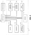
- a horticultural assembly 10 can be at any location, including outdoors, in a green house, indoors or the like.
- the assembly 10 includes a container or space 12 where plants 14 that are typically planted in side by side relation are located.
- the container 12 is provided that is an incubating device that in one embodiment is generally rectangular in shape having first and second sidewalls 15 and 16 in paralleled spaced relation secured to top and bottom walls 18 and 20 also in paralleled spaced relation and a back wall 22 to form and hollow interior cavity 24.
- a front wall or door is hingedly secured to a sidewall 15 or 16 to allow access to the interior cavity 24 of the body 12.
- the door is made of a transparent material to allow the interior cavity 24 to be seen, though in another embodiment the door completely encloses the interior cavity 24.
- the soil masses 30 are of size and shape to be received and held by the openings 29 of the trays 28.
- the trays 28 rotate or tilt to various angles to ensure complete coverage of the lights on the soil masses 30 and seedlings 31.
- a plurality of lighting elements 32 are secured to each tray 28 and electrically connected to one another.
- the plurality of lighting elements 32 are light emitting diode elements that receive an AC input.
- these assemblies incorporate AC driven LED technology from any one of the following patent applications: U.S. Pat. Pub. No. 2011/0101883 to Grajcar ; U.S. Pat. Pub. No. 2011/0109244 to Grajcar ; U.S. Pat. Pub. No. 2011/0210678 to Grajcar ; U.S. Pat. Pub. No. 2011/0228515 to Grajcar ; U.S. Pat. Pub. No. 2011/0241559 to Grajcar ; U.S. Pat. Pub. No. 2011/0273098 to Grajcar ; U.S. Pat. Appl. No. 13/452332 to Grajcar ; or U.S. Pat. Prov. Appl. No. 61/570,552 to Grajcar .
- each lighting element 32 causes the emission of blue wavelength (450-495 nm) light, ultraviolet light and near ultraviolet light (350-450 nm), red light (620-750 nm) or electromagnetic radiation is utilized.
- lighting elements 32 have electromagnetic radiation/ultraviolet/blue wavelength lighting elements and red wavelength elements combined on the same tray 28 as shown in Fig. 3 as lighting elements 32a and 32b.
- Such blue and red wavelength lighting elements 32a and 32b in one embodiment have light duration periods that are different. So, as an example, a first blue wavelength lighting element has a light duration period of 3 ms while a red wavelength lighting element has a light duration of 2 seconds.
- the lighting elements 32a and 32b have the same duration only staggered.
- a first blue wavelength lighting element 32a has a duration or period of 3 ms of light and 3 ms of dark.
- a second red wavelength lighting element 32b is also provided on the tray that also has a duration or period of 3 ms of light and 3 ms of dark.
- the first and second lighting elements emit light at the same time or present an overlap.
- the second red wavelength lighting element is dark during the 3 ms the first blue wavelength lighting element is producing light. Then when the second red wavelength lighting element is producing light for 3 ms the first blue lighting element in dark and not emitting light.
- the lighting elements 32 are powered by an electrical power source 33 and further have a dimming device 34 that causes the intensity of the light to be reduced to less than 3 lumens.
- a constant low intensity wavelength light is emitted throughout the container 12.
- the light can be of a narrow frequency or monochromatic to direct the exact wavelength of light desired.
- a higher intensity wavelength of light can be provided.
- the lights can be left on for long durations of time.
- the intensity of the light can be reduced to less than 3 lumens, the intensity of the light similarly can be increased to output 800 lumens, 1000 lumens or more.
- light duration can be for long periods of time such as days, weeks or months, the duration between light and dark periods can also be controlled to hours, minutes, seconds and even ml seconds.
- a humidifying device 36 is also associated with the interior cavity 24 and preferable engages the top wall 18 and has a tubing element that can increase the humidity within the interior cavity 24 when the door 26 is closed. In this manner the humidity within the interior can be controlled to provide any relative humidity from 0% humidity to 100%, such that the humidity with the interior cavity 24 is predetermined. Preferably the humidity is approximately between 50-80%.
- a heating device 38 is also electrically connected to the power source 33 and disposed within the interior cavity 24 to provide a predetermined amount of heat within the interior cavity.
- a magnetic field source device 40 is associated with the incubating device 10. In one embodiment the magnetic field source device 40 is within the interior cavity to form a predetermined magnetic flux through or affecting the seedlings 31 and resulting plants 14.
- intensity of each lighting element is another consideration.
- intensity or lumens/m2 or lux on the plant 14 or seedling 31 increases the amount of energy being supplied to the plant 14 or seedling 31 is increased, thus lessening the amount of time needed to provide the proper dose, or energy needed to create the photochemical reaction, or photosynthesis.
- the dose of energy required to cause the chemical reaction increases.
- the dose needed to cause photosynthesis is dynamic. Therefore the amount of time needed to provide sufficient energy to cause the photochemical reaction or photosynthesis can actually increase during a day or over time, such that in the beginning of a period of lighting, the optimum dose is provided with a first predetermined amount of time, such as 3.5 ms and after a period of time such as 12 hours, a second predetermined amount of time, such as 14.5 ms of light is required.
- an algorithm for each plant 14 or seedling 31 can be provided that is specifically tailored or dynamically changes the frequency or photoperiod of the lighting elements 32 throughout a predetermined time period, such as twelve (12) hours, twenty-four (24) hours, forty-eight (48) hours or greater.
- a predetermined time period such as twelve (12) hours, twenty-four (24) hours, forty-eight (48) hours or greater.
- the intensity of the light can be dynamically changed by the controller 200, either by increasing and decreasing voltage and thus light output intensity or by having the controller 200 electrically connected to tray actuators 39 that mechanically raises and lowers the trays 28 to bring the lighting elements 32 closer or further away from the plants 14 or seedlings 31.
- a sensor 41 can be electrically connected to the controller 200 to determine the height of a plant 14, and automatically and dynamically move the tray 28 away from the plant 14 to ensure the correct intensity is always provided to the plant.
- the lighting elements 32 in one embodiment are placed or mounted adjacent the plants 14 such that at least one plant receives radiation emitted by the lighting elements 32.
- the lighting elements 32 are dimmable and are constructed as is described in U.S. Patent application serial No. 12/824,215 to Grajcar and/or U.S. Patent application serial No. 12/914,575 to Grajcar .
- One such assembly is shown in FIG. 4 having an pair of input terminals 50 that are adapted to receive a periodic excitation voltage such that the terminals can receive AC current or a current of equal magnitude and opposite polarity, said current flowing in response to the excitation voltage to provide an AC input.
- the AC current is then conditioned by driving circuitry 52 that optionally includes an metal oxide varesistor (MOV) 54 and a rectifying device 55 that in a preferred embodiment is a bridge rectifier formed of a plurality of light emitting diodes (LEDs) 56.
- MOV metal oxide varesistor
- rectifying device 55 that in a preferred embodiment is a bridge rectifier formed of a plurality of light emitting diodes (LEDs) 56.
- the light emitting diodes (LEDs) 56 are arranged in a first network 58 where the first network 58 is arranged to conduct the current in response to the excitation voltage exceeding at least a forward threshold voltage associated with the first network 58.
- a resistor 60 or multiple resistors can be used to condition the current before reaching the first network 58.
- the LEDs 56 of the first network 58 can be of any type or color.
- the LEDs 56 of the first network 58 are red LEDs that produce light having a wavelength of approximately 600-750 nano meters (nm).
- the first network of LEDs are blue LEDs that produce light having a wavelength of approximately 350-500 nm.
- both red and blue LEDs can be provided together or other colored LEDs such as green may similarly be used without falling outside the scope of this disclosure.
- a second network 62 having a plurality of LEDs 56 is additionally provided in series relationship with the first network 58.
- the LEDs 56 of the second network 62 can be of any type or color.
- the LEDs 56 of the second network 62 are red LEDs that produce light having a wavelength of approximately 600-750 nano meters (nm).
- the second network of LEDs are blue LEDs that produce light having a wavelength of approximately 350-500 nm.
- both red and blue LEDs can be provided together or other colored LEDs such as green may similarly be used without falling outside the scope of this disclosure.
- a bypass path 64 is provided in the lighting element 32 that is in series relationship with the first network 58 and in parallel relationship with the second network 62. Also within the bypass path 64 are elements that provide a controlled impedance, which can be, for example only a transistor 66 that in one embodiment is a depletion MOSFET. Additional transistors, resistors or the like can be used within the bypass path 64 all that condition current to provide the smooth and continuous transition from the bypass path 64 to the second network 62.
- color temperature shifting as a function of input excitation waveforms may be implemented or designed based on appropriate selection of LED groups or networks 58 and 62 and arrangement of one or more selective current diversion conditioning circuits to modulate a bypass current around selected LED networks 58 and 62.
- the selection of the number of diodes in each group, excitation voltage, phase control range, diode colors, and peak intensity parameters may be manipulated to yield improved electrical and/or light output performance for a range of lighting applications.
- the lighting elements 32 are able to be modulated using the dimming device 34 without utilization of a DC power source.
- the dimming device 34 utilizes leading edge and falling edge phase cutting elements.
- a triac dimmer presents phase cutting at a leading edge while an IGBT dimmer presents phase cutting at a trailing edge.
- the dimming device having both leading edge and trailing edge phase cutting is in electrical communication with the driving circuitry 52. In this manner by utilizing both in a dimming device 34 a predetermined period of no current is provided. Thus a control device associated with the dimming device 34 can be used to determine the period of no current and thus period of dark.
- the dimming device 34 includes at least one SCR silicon controlled rectifier) and in one embodiment first and second SCRs that are utilized to cut current provided for a predetermined period of time. The cut can occur at a 0 phase angle or alternatively at an angle.
- the dimming device 34 again functions as a controllable on/off switch of the lighting elements 32.
- the control device such as a control knob is in communication with first and second SCRs such that the predetermined period of light and dark can be set at any predetermined time period from 0-30 minutes. Because an AC input is provided, the dark provided is a complete darkness where no photons are being produced as a result of no current being provided, unlike DC based flicker. In this manner one can control the predetermined durations of light and dark to match the requirements of specific plants.
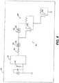
- Fig. 6 shows an alternative embodiment that allows for the staggering of different lighting elements 32a and 32b.
- This embodiment shows a circuit 68 having an AC input 70 that provides AC current to driving circuitry 69 that includes a half of a bridge rectifier 72 to supply an input in a first plurality of lighting elements 32a that in one embodiment provide a red spectral output. Then in parallel the second plurality of lighting elements 32b receive an input from the AC input through a diode 74, such as a zener diode.
- a diode 74 such as a zener diode.
- Each group of lighting elements 32a and 32b also have additional current conditioning elements that in this embodiment are provided as a transistors with controlling resistors.
- Fig. 7 shows the voltage input 80 and current inputs 82 and 84 to lighting elements 32a and 32b resulting from circuit 68.
- the first current input 82 provides a maximum current input 86 when positive voltage is applied to the circuit and no current 88 when voltage input 80 drops below zero (0).
- the second current input 84 provides a maximum current input 90 when voltage is negative, or below zero, while no current 92 is presented when the voltage is above zero or positive.
- the current frequency to each set of lighting elements 32a and 32b is offset such that during a period when no current is flowing to the first lighting elements 32a, causing darkness in first lighting elements 32a, current is flowing to second lighting elements 32b causing light to be provided by the second lighting elements 32b and vice versa.
- a human perceives continuous light, but the plant receives a period of wavelength of light it absorbs and then a period of light it does not absorb, and thus the individual pigments perceive light and dark periods.
- the lighting elements 32a and 32b are controlled to provide varying periods of light to a plant. So, a single lighting element 32a is driven to provide light at a first time, then not emit light able to be absorbed by the plant for a predetermined amount of time based on a predetermined period of time required for a predetermined chemical reaction within the plant to occur and then light is again emitted by the lighting element 32 and then no longer emits light able to be absorbed the plant for a second predetermined period of time to allow a second chemical reaction to occur, wherein the first and second predetermined periods of time can be equal or different and each causes a predetermined biological effect within the plant.
- differing periods between emitting absorbable light is provided wherein such differing periods include, but are not limited to 30 ⁇ s, 70 ⁇ s, 190 ⁇ s, 200 ⁇ s or 1.1 ms, or 15-40ps or 5-6ns without falling outside the scope of this disclosure.
- an algorithm can be developed based on individual plant needs in order to time the period of absorbing light vs an output, including dark, that is not absorbed by to cause a chemical reaction.
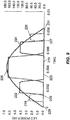
- Figs. 8 and 9 show an alternative circuit 201 and graph of the wave output thereof, respectively.
- the circuit 201 has an input 202 providing electrical excitation of opposing magnitudes that is rectified by a rectifier 204 and provided to a series of lighting elements 206, 208 and 210 are provided in parallel to one another. While each of the first, second and third lighting elements 206, 208 and 210 are shown as a single diode, those skilled in the art understand that schematically that each lighting element shown comprises a plurality of series connected light emitting diodes.
- Each lighting element 206, 208 or 210 can be the same or different wavelength and preferably a wavelength within 20 nm of a peak absorbance wavelength of a pigment of plant 30 that receives the light emitted.
- the first lighting element 206 is a first wavelength while the second and third lighting elements 208 and 210 are different wavelengths.
- First, second and third impedance elements 212, 214 and 216 that preferable are transistors and more preferably are MOSFETs are arranged in the circuit 201 with resistors 217 and in bypass paths to provide the output shown in Fig. 9 .
- the first lighting elements 206 receive power and emit light for a first light interval 218 that is a first predetermined interval of time followed by a first dark interval 219 over a predetermined amount of time and a then a second light interval 220.
- the second lighting elements 208 provide a third light interval 222 that is a predetermined amount of time that is different than the predetermined amount of time of the first and second light intervals 218 and 220 followed by a second dark interval 223 and then a fourth light interval 224.
- the third lighting elements 210 present a third dark interval 225, a fifth light interval 226 and a fourth dark interval 227.
- a fifth dark interval 229 occurs preceding the first light interval 218 and a sixth dark interval occurs following the second light interval 220.
- light and dark intervals can be manipulated to provide non synchronous or varying intervals of light and dark.
- a phase cutting dimmer is utilized to control the fifth and sixth dark intervals 229 and 231 to vary time between pulses of light intervals to provide off or dark time proportional to turnover time of the photosynthetic electron transport chain to reduce photoinhibition rate.
- the intervals of light and dark can be varied to shorten the periods of light proportional to transient properties of the plant to provide maximum intake of light with minimum power utilized.
- LED lighting elements 32 have been described along with an incubation chamber type structure, any type of light source that is able to deliver varying wavelengths of light or different photoperiods of light to any environment where artificial light is used to grow a plant is contemplated by this disclosure and such embodiments to not fall outside of this disclosure.
- This also includes, but is not limited in using a PWM driver with a controller that modulates the frequency of the driver to provide varying outputs that coincide with varying predetermined time periods associated with varying predetermined biological responses of the plant.
- the wavelength, or color of light one determines the light wavelengths or colors for a plant that enhances a characteristic of the plant, such as growth, yield, root growth, or the like.
- a characteristic of the plant such as growth, yield, root growth, or the like.
- light that is suited to be absorbed by the chlorophylls or carotenoids within a plant is provided to provide additional energy to the plant for chemical reactions that enhance photosynthesis. In this manner, light that is at a wavelength that is absorbed by the chlorophyll also enhances and promotes more efficient photosynthesis.
- this wavelength is 680nm and in another embodiment 700nm.
- lighting elements 32 are manufactured to present the predetermined light wavelength and the dimming device 34 can be adjusted to provide predetermined light and dark periods for enhanced growth.
- the manner in which the duration is accomplished is also selected.
- the plant is again analyzed to determine if an additional pigment is presented within the plant.
- chlorophyll A present the plant is reanalyzed to determine if chlorophyll B is also present. If chlorophyll B is also present a second lighting element or plurality of lighting elements can then be selected. As with the first lighting element, the second lighting element is selected having a narrow band of wavelengths that relate to a peak 120, 125, 130, 135, 140, 145, 150, 155 or 160 of a pigment (chlorophyll A, chlorophyll B or carotenoid) within the plant.
- the duration of time for the dose or amount of light needed to complete the chemical reaction of photosynthesis is determined.
- a method of providing the needed duration of light and dark, as described above is provided for the second lighting element.
- both the first and second lighting elements provide the exact wavelength of light and duration of light and darkness as the pigments required within the plant, thus enhancing plant growth.
- This method can similarly be used related to the carotenoid pigment and other chemicals within the plant. In this manner multiple different wavelengths are utilized at different periods in a cycle to arrive at a lighting treatment for enhancing photosynthesis.
- a first lighting element can be presented that presents 680 nm wavelength light at an intensity, or fluence and first period of time or duration that causes the P680 activation center to react and then a second period of time or duration for that specific lighting element is provided where light either is not presented or presented at an intensity or fluence that the output minimizes the auxiliary chemical reactions occurring while the chemical reaction or movement of the electron along the photosynthetic electron transport chain is moving forward.
- a second lighting element that is adjacent to the first lighting element, whether in the same device or not is provided that is a different wavelength than the first lighting element.
- the second light element provides the second wavelength at an intensity and first period of time to provide an amount of light to enhance photosynthesis.
- This first period of time for the second lighting element can be during the first period of time for the first lighting element, overlap the first period of time or can be during the second period of time of the first lighting element when no light or limited intensity is presented.
- a first constant background light at a first lower intensity at a first wavelength such as, for example only, 410 nm or 500 nm is provided for an extended period of time, such as, for example only at least one minute, alternatively, at least an hour or alternatively twenty-four hours.
- the second light element provides another wavelength, such as, for example only, 680 nm that is pulsed, or light is provided on and off for predetermined periods of less than a second and in one embodiment varying times related to the time periods within the Kok cycle.
- the time between photon release may be presented as a dark period or time when a light source emits no photons
- the time between periods when photons are ready to be accepted can also be filled with light emitted at intensities or wavelengths that are not absorbed by reactive components within the PSII or PSI complexes.
- P680 absorbs 680nm wavelength light to result in the photochemical reactions desired; however, 450nm blue or even wavelengths that are less than 450nm and into the UV range 100nm-400nm could be utilized to cause other chemical reactions within a plant and not absorbed by the P680, such that such light does not cause the photo damage contemplated by this disclosure.
- the plant is analyzed to determine the effect the second wavelength of light has on other reactive centers within the plant such as P680 and other chemicals present to again minimize harmful chemical reactions that cause the plant to use energy to protected or repair damage instead of for photosynthesis.
- light at the second wavelength may be provided at an intensity or fluence and period of time that is harmful to the plant; however, the enhancement or improvement resulting in providing the energy to the plant makes the overall process more efficient and enhances photosynthesis.
- additional lighting elements presenting additional wavelengths for additional periods of time that correspond to different desired chemical reactions are contemplated.
- a third lighting element providing light at a wavelength of 700 or 720nm corresponding to the peak absorption level of the reactive center of PS1 similarly is utilized.
- an individual plant is studied and different wavelengths of light provided at different time periods and intensities to minimize harmful chemical reactions within the plant and maximizing the performance of chemicals and chemical reactions to enhance photosynthesis through use of the lighting device.
- predetermined periods of light and dark that stimulate continuous growth of the plant.
- predetermined periods of light and dark are measured or determined by what can be perceived by a plant 14 and represents periods when no light is being emitting by the lighting elements 32, even if the light or dark cannot be perceived by a human.
- flicker and unperceivable flicker present that is not perceived by humans is considered to provide a predetermined period of light and dark within the context of this disclosure.
- PTC photosynthetic electron transport chain
- the deep red, royal blue and lime green each pulsed simultaneously in 4 pulse intervals with each pulse width being approximately 30 ⁇ s and after the first pulse approximately 85 ⁇ s of no light was provided before a second pulse of 30 ⁇ s. Then a period of approximately 230 ⁇ s of no light was provided before a third pulse of 30 ⁇ s. Then approximately 240 ⁇ s of no light was provided before a fourth pulse of 30 ⁇ s. Finally, a period of approximately 1360 ⁇ s of no light occurred before this cycle was restarted and maintained in this pattern for 24 hours until the plant was fully grown.
- the deep red and royal blue outputs where identical to the first chamber with 4 pulse intervals occurring at the identical times as described in the previous paragraph.
- the lime green light source however did not pulse at the same intervals as the deep red and royal blue light sources. Instead the lime green light source pulsed once per cycle for 1200 ⁇ s, starting 80 ⁇ s after the end of the fourth 30 ⁇ s pulse (within the 1360 ⁇ s interval or period between the ending of a cycle of four pulses and beginning of a new cycle of four pulses) of the deep red and royal blue light sources and ending 80 ⁇ s before the first 30 ⁇ s pulse of the next cycle of 4 pulses. This pattern was then maintained for 24 hours.
- the final chamber was the control chamber that provided constant DC light of deep red, royal blue and lime green for 24 hours. There was 20% royal blue and 20% lime green compared to the deep red and the current was adjusted to ensure the exact same amount of light reached the control plants as in the first and second chambers.
- each photon is thus provided at the time required for a predetermined chemical reaction to take place and excess photons that are used in chemical reactions that damage the plant are minimized if not eliminated. By minimizing damage, growth is enhanced, causing faster growth and greener, better developed plant life.
- PETC photosynthetic electron transport chain
- light treatments are provided that increase the weight and density of a plant, or can increase leaf size, increase or decrease root structure or manipulate a predetermined characteristic of the plant to provide a customized growth of the plant meeting the needs of the grower. This includes, but is not limited to increasing nutrients within the plant, faster growth of the part of the plant that is an end product for consumers and color or look of the plant.
- the assembly 10 includes lighting elements 32 that provide a lighting cycle or phase that includes a predetermined amount of dark or turnover time for the plant.
- the plant 14 gets the needed rest to relieve plant stress and strain during the completion of the metabolizing process. At this point the plant 14 is then ready to absorb more light to continue metabolizing in the photosynthesis process.
- LEDs can comprise the different networks 58 and 62 of LEDs to create intermittent UV, near UV, blue light and/or red light in light received by the plants 14 according to the ideal PAR for that particular plant 14.
- LEDs can comprise the different networks 58 and 62 of LEDs to create intermittent UV, near UV, blue light and/or red light in light received by the plants 14 according to the ideal PAR for that particular plant 14.
- assemblies 10 are easily manufactured and incorporated into new and existing horticulture assemblies by mounting or placing them otherwise adjacent to the plants 14.
- current is conditioned from an AC input is utilized and pulse width modulation eliminated, the cost associated with the lighting element 32 is greatly reduced.
Priority Applications (1)
| Application Number | Priority Date | Filing Date | Title |
|---|---|---|---|
| EP19175816.8A EP3609297A1 (en) | 2014-07-21 | 2015-07-21 | Photonic engine system for actuating the photosynthetic electron transport chain |
Applications Claiming Priority (4)
| Application Number | Priority Date | Filing Date | Title |
|---|---|---|---|
| US201462027049P | 2014-07-21 | 2014-07-21 | |
| US201462061933P | 2014-10-09 | 2014-10-09 | |
| US201562102637P | 2015-01-13 | 2015-01-13 | |
| PCT/US2015/041236 WO2016014456A1 (en) | 2014-07-21 | 2015-07-21 | Photonic engine system for actuating the photosynthetic electron transport chain |
Related Child Applications (1)
| Application Number | Title | Priority Date | Filing Date |
|---|---|---|---|
| EP19175816.8A Division EP3609297A1 (en) | 2014-07-21 | 2015-07-21 | Photonic engine system for actuating the photosynthetic electron transport chain |
Publications (3)
| Publication Number | Publication Date |
|---|---|
| EP3193579A1 EP3193579A1 (en) | 2017-07-26 |
| EP3193579A4 EP3193579A4 (en) | 2018-03-28 |
| EP3193579B1 true EP3193579B1 (en) | 2019-05-22 |
Family
ID=55073387
Family Applications (2)
| Application Number | Title | Priority Date | Filing Date |
|---|---|---|---|
| EP15824334.5A Not-in-force EP3193579B1 (en) | 2014-07-21 | 2015-07-21 | Photonic engine system for actuating the photosynthetic electron transport chain |
| EP19175816.8A Withdrawn EP3609297A1 (en) | 2014-07-21 | 2015-07-21 | Photonic engine system for actuating the photosynthetic electron transport chain |
Family Applications After (1)
| Application Number | Title | Priority Date | Filing Date |
|---|---|---|---|
| EP19175816.8A Withdrawn EP3609297A1 (en) | 2014-07-21 | 2015-07-21 | Photonic engine system for actuating the photosynthetic electron transport chain |
Country Status (6)
| Country | Link |
|---|---|
| US (1) | US20160014974A1 (zh) |
| EP (2) | EP3193579B1 (zh) |
| JP (1) | JP6796578B2 (zh) |
| KR (1) | KR20170058915A (zh) |
| CN (1) | CN107072149B (zh) |
| WO (1) | WO2016014456A1 (zh) |
Families Citing this family (25)
| Publication number | Priority date | Publication date | Assignee | Title |
|---|---|---|---|---|
| US10028448B2 (en) | 2012-07-10 | 2018-07-24 | Once Innovations, Inc. | Light sources adapted to spectral sensitivity of plants |
| US10212892B2 (en) | 2012-07-10 | 2019-02-26 | Once Innovatians, Inc. | Light sources adapted to spectral sensitivity of plant |
| US11278009B2 (en) | 2013-03-05 | 2022-03-22 | Xiant Technologies, Inc. | Photon modulation management system for stimulation of a desired response in birds |
| US10182557B2 (en) | 2013-03-05 | 2019-01-22 | Xiant Technologies, Inc. | Photon modulation management system for stimulation of a desired response in birds |
| US9844209B1 (en) | 2014-11-24 | 2017-12-19 | Xiant Technologies, Inc. | Photon modulation management system for stimulation of a desired response in birds |
| EP3131384A4 (en) * | 2014-04-17 | 2017-12-13 | Once Innovations, Inc. | Light sources adapted to spectral sensitivity of plants |
| US10244595B2 (en) | 2014-07-21 | 2019-03-26 | Once Innovations, Inc. | Photonic engine system for actuating the photosynthetic electron transport chain |
| CN106793757B (zh) | 2014-08-29 | 2020-12-29 | 现特技术有限公司 | 光子调制管理系统 |
| WO2016167072A1 (ja) * | 2015-04-14 | 2016-10-20 | 興和株式会社 | 植物栽培用照明システム |
| EP3143869A1 (en) * | 2015-09-17 | 2017-03-22 | Université d'Avignon et des Pays de Vaucluse | Method for stimulating the resistance of plants to biotic stress by uv radiation exposure |
| US10745478B2 (en) | 2016-02-19 | 2020-08-18 | Dignity Health | Antibody fusion protein and related compositions for targeting cancer |
| US20170295727A1 (en) * | 2016-04-19 | 2017-10-19 | Suntracker Technologies Ltd. | Temporally modulated lighting system and method |
| US11058889B1 (en) | 2017-04-03 | 2021-07-13 | Xiant Technologies, Inc. | Method of using photon modulation for regulation of hormones in mammals |
| JP6885360B2 (ja) * | 2017-04-28 | 2021-06-16 | 日亜化学工業株式会社 | 植物中のフェノール性化合物の増量方法 |
| US11304390B2 (en) * | 2017-05-08 | 2022-04-19 | Urban Planter, Llc | Automated vertical plant cultivation system |
| US11622510B2 (en) | 2017-05-08 | 2023-04-11 | Urban Planter, Llc | Automated vertical plant cultivation system |
| US11617309B2 (en) | 2017-05-08 | 2023-04-04 | Urban Planter, Llc | Automated vertical plant cultivation system |
| US10524433B2 (en) | 2017-05-08 | 2020-01-07 | Daniel S. Spiro | Automated vertical plant cultivation system |
| JP7037036B2 (ja) * | 2017-09-22 | 2022-03-16 | 日亜化学工業株式会社 | 発光ダイオード駆動装置及びこれを用いた植物栽培用照明 |
| US11778955B2 (en) | 2017-11-29 | 2023-10-10 | Urban Planter, Llc | Automated vertical plant cultivation system |
| US11483981B1 (en) * | 2018-05-14 | 2022-11-01 | Crop One Holdings, Inc. | Systems and methods for providing a low energy use farm |
| WO2020033127A1 (en) | 2018-08-10 | 2020-02-13 | Rosstech, Inc. | Tunable led light array for horticulture |
| US11291164B2 (en) | 2018-08-24 | 2022-04-05 | Seoul Viosys Co., Ltd. | Light source for plant cultivation |
| US10820532B2 (en) | 2018-08-24 | 2020-11-03 | Seoul Viosys Co., Ltd. | Light source for plant cultivation |
| EP3735822B1 (en) * | 2019-05-09 | 2021-09-15 | P3 B.V. | Method for growing aquatic organisms capable of photosynthesis in a controlled aqueous environment |
Family Cites Families (21)
| Publication number | Priority date | Publication date | Assignee | Title |
|---|---|---|---|---|
| JPS61146122A (ja) * | 1984-12-19 | 1986-07-03 | 三菱電機株式会社 | 植物育成用照明装置 |
| US4749916A (en) * | 1984-12-19 | 1988-06-07 | Mitsubishi Denki Kabushiki Kaisha | Illuminator for cultivating plant |
| US5012609A (en) * | 1988-12-12 | 1991-05-07 | Automated Agriculture Associates, Inc. | Method and apparatus for irradiation of plants using optoelectronic devices |
| CA2400241C (en) * | 2000-02-22 | 2008-12-02 | Ccs Inc. | Illuminator for plant growth |
| WO2008149286A2 (en) * | 2007-06-05 | 2008-12-11 | Philips Intellectual Property & Standards Gmbh | A lighting system for horticultural applications |
| US8643308B2 (en) | 2009-08-14 | 2014-02-04 | Once Innovations, Inc. | Spectral shift control for dimmable AC LED lighting |
| US8373363B2 (en) | 2009-08-14 | 2013-02-12 | Once Innovations, Inc. | Reduction of harmonic distortion for LED loads |
| US8531136B2 (en) | 2009-10-28 | 2013-09-10 | Once Innovations, Inc. | Architecture for high power factor and low harmonic distortion LED lighting |
| EP2493723B1 (en) | 2009-10-29 | 2021-09-15 | Signify North America Corporation | Led lighting for livestock development |
| GB201000593D0 (en) * | 2010-01-14 | 2010-03-03 | Morris Peter J | Photo-bioreactor and method for cultivating biomass by photosynthesis |
| US8302346B2 (en) * | 2010-01-26 | 2012-11-06 | University Of Georgia Research Foundation, Inc. | Biological optimization systems for enhancing photosynthetic efficiency and methods of use |
| EP4151087B1 (en) | 2010-03-17 | 2024-05-08 | Signify North America Corporation | Light sources adapted to spectral sensitivity of diurnal avians |
| US8651691B2 (en) | 2010-03-31 | 2014-02-18 | Once Innovations, Inc. | Integral conduit modular lighting |
| CN201846642U (zh) * | 2010-08-23 | 2011-06-01 | 林清源 | 开放式利用人工光的非环境控制型家庭植物工厂 |
| EP2740349B1 (en) * | 2011-08-05 | 2020-02-26 | Showa Denko K.K. | Algae cultivation method |
| JP2013106550A (ja) * | 2011-11-18 | 2013-06-06 | Sharp Corp | 植物育成用照明装置 |
| US20140069007A1 (en) * | 2012-09-13 | 2014-03-13 | Cashido Corporation | Plant growth facilitating apparatus plant growth facilitating apparatus |
| US10602669B2 (en) * | 2012-10-15 | 2020-03-31 | Symbiotic Systems, Inc. | Narrowband photosynthetically active radiation (“PAR”) substantially only at each of multiple emission wavelengths yields good photosynthesis at reduced energy cost |
| WO2014085626A1 (en) * | 2012-11-27 | 2014-06-05 | University Of Florida Research Foundation, Inc. | Light modulation of plants and plant parts |
| CA2888618A1 (en) * | 2012-12-20 | 2014-06-26 | Heliospectra Ab | Method and illumination system for plant recovery from stress |
| US9526215B2 (en) * | 2013-03-05 | 2016-12-27 | Xiant Technologies, Inc. | Photon modulation management system |
-
2015
- 2015-07-21 WO PCT/US2015/041236 patent/WO2016014456A1/en active Application Filing
- 2015-07-21 EP EP15824334.5A patent/EP3193579B1/en not_active Not-in-force
- 2015-07-21 US US14/804,410 patent/US20160014974A1/en not_active Abandoned
- 2015-07-21 KR KR1020177004560A patent/KR20170058915A/ko unknown
- 2015-07-21 EP EP19175816.8A patent/EP3609297A1/en not_active Withdrawn
- 2015-07-21 JP JP2017503948A patent/JP6796578B2/ja active Active
- 2015-07-21 CN CN201580049505.XA patent/CN107072149B/zh not_active Expired - Fee Related
Non-Patent Citations (1)
| Title |
|---|
| None * |
Also Published As
| Publication number | Publication date |
|---|---|
| CN107072149A (zh) | 2017-08-18 |
| EP3193579A1 (en) | 2017-07-26 |
| US20160014974A1 (en) | 2016-01-21 |
| KR20170058915A (ko) | 2017-05-29 |
| JP6796578B2 (ja) | 2020-12-09 |
| EP3193579A4 (en) | 2018-03-28 |
| CN107072149B (zh) | 2019-12-31 |
| WO2016014456A1 (en) | 2016-01-28 |
| JP2017521087A (ja) | 2017-08-03 |
| EP3609297A1 (en) | 2020-02-12 |
Similar Documents
| Publication | Publication Date | Title |
|---|---|---|
| US10813183B2 (en) | Photonic engine system for actuating the photosynthetic electron transport chain | |
| EP3193579B1 (en) | Photonic engine system for actuating the photosynthetic electron transport chain | |
| US10973173B2 (en) | Light sources adapted to spectral sensitivity of plants | |
| Gupta et al. | Light emitting diodes for agriculture | |
| WO2016115235A1 (en) | System for actuating photosynthetic electron transport chain | |
| AU2011347053B2 (en) | Method and means for acclimatizing seedlings for outdoor life | |
| CN111511057B (zh) | 光子调制管理系统 | |
| CN106413382B (zh) | 适应于植物的光谱灵敏度的光源 | |
| EP3127421B1 (en) | Illumination device for plant growth and plant growing method | |
| KR100944359B1 (ko) | 식물 재배용 다광원 조명장치 및 이를 이용한 식물 재배 방법 | |
| CN105142392A (zh) | 光子调制管理系统 | |
| US20150273235A1 (en) | Devices and method of causing chemical reaction to supplement vitamin d production | |
| US20220061227A1 (en) | Devices for an optimized, high-intensity, horticultural, led luminaire having a regulated photosynthetic flux density | |
| CN111448904A (zh) | 一种光调控黄瓜育苗方法及光照设备 | |
| Hawley | Development of a variable-spectra LED array for optimized plant development | |
| JP2023501700A (ja) | 植物栽培用光源及び植物栽培方法 |
Legal Events
| Date | Code | Title | Description |
|---|---|---|---|
| STAA | Information on the status of an ep patent application or granted ep patent |
Free format text: STATUS: THE INTERNATIONAL PUBLICATION HAS BEEN MADE |
|
| PUAI | Public reference made under article 153(3) epc to a published international application that has entered the european phase |
Free format text: ORIGINAL CODE: 0009012 |
|
| STAA | Information on the status of an ep patent application or granted ep patent |
Free format text: STATUS: REQUEST FOR EXAMINATION WAS MADE |
|
| 17P | Request for examination filed |
Effective date: 20170217 |
|
| AK | Designated contracting states |
Kind code of ref document: A1 Designated state(s): AL AT BE BG CH CY CZ DE DK EE ES FI FR GB GR HR HU IE IS IT LI LT LU LV MC MK MT NL NO PL PT RO RS SE SI SK SM TR |
|
| AX | Request for extension of the european patent |
Extension state: BA ME |
|
| DAV | Request for validation of the european patent (deleted) | ||
| DAX | Request for extension of the european patent (deleted) | ||
| A4 | Supplementary search report drawn up and despatched |
Effective date: 20180222 |
|
| RIC1 | Information provided on ipc code assigned before grant |
Ipc: A01F 7/00 20060101AFI20180217BHEP |
|
| REG | Reference to a national code |
Ref country code: DE Ref legal event code: R079 Ref document number: 602015030932 Country of ref document: DE Free format text: PREVIOUS MAIN CLASS: A01F0007000000 Ipc: A01G0007040000 |
|
| GRAP | Despatch of communication of intention to grant a patent |
Free format text: ORIGINAL CODE: EPIDOSNIGR1 |
|
| STAA | Information on the status of an ep patent application or granted ep patent |
Free format text: STATUS: GRANT OF PATENT IS INTENDED |
|
| RIC1 | Information provided on ipc code assigned before grant |
Ipc: H05B 33/08 20060101ALN20181029BHEP Ipc: A01G 7/04 20060101AFI20181029BHEP |
|
| INTG | Intention to grant announced |
Effective date: 20181203 |
|
| GRAS | Grant fee paid |
Free format text: ORIGINAL CODE: EPIDOSNIGR3 |
|
| GRAA | (expected) grant |
Free format text: ORIGINAL CODE: 0009210 |
|
| STAA | Information on the status of an ep patent application or granted ep patent |
Free format text: STATUS: THE PATENT HAS BEEN GRANTED |
|
| AK | Designated contracting states |
Kind code of ref document: B1 Designated state(s): AL AT BE BG CH CY CZ DE DK EE ES FI FR GB GR HR HU IE IS IT LI LT LU LV MC MK MT NL NO PL PT RO RS SE SI SK SM TR |
|
| REG | Reference to a national code |
Ref country code: GB Ref legal event code: FG4D |
|
| REG | Reference to a national code |
Ref country code: CH Ref legal event code: EP |
|
| REG | Reference to a national code |
Ref country code: IE Ref legal event code: FG4D |
|
| REG | Reference to a national code |
Ref country code: DE Ref legal event code: R096 Ref document number: 602015030932 Country of ref document: DE |
|
| REG | Reference to a national code |
Ref country code: AT Ref legal event code: REF Ref document number: 1134946 Country of ref document: AT Kind code of ref document: T Effective date: 20190615 |
|
| REG | Reference to a national code |
Ref country code: NL Ref legal event code: FP |
|
| REG | Reference to a national code |
Ref country code: LT Ref legal event code: MG4D |
|
| PG25 | Lapsed in a contracting state [announced via postgrant information from national office to epo] |
Ref country code: AL Free format text: LAPSE BECAUSE OF FAILURE TO SUBMIT A TRANSLATION OF THE DESCRIPTION OR TO PAY THE FEE WITHIN THE PRESCRIBED TIME-LIMIT Effective date: 20190522 Ref country code: PT Free format text: LAPSE BECAUSE OF FAILURE TO SUBMIT A TRANSLATION OF THE DESCRIPTION OR TO PAY THE FEE WITHIN THE PRESCRIBED TIME-LIMIT Effective date: 20190922 Ref country code: SE Free format text: LAPSE BECAUSE OF FAILURE TO SUBMIT A TRANSLATION OF THE DESCRIPTION OR TO PAY THE FEE WITHIN THE PRESCRIBED TIME-LIMIT Effective date: 20190522 Ref country code: FI Free format text: LAPSE BECAUSE OF FAILURE TO SUBMIT A TRANSLATION OF THE DESCRIPTION OR TO PAY THE FEE WITHIN THE PRESCRIBED TIME-LIMIT Effective date: 20190522 Ref country code: LT Free format text: LAPSE BECAUSE OF FAILURE TO SUBMIT A TRANSLATION OF THE DESCRIPTION OR TO PAY THE FEE WITHIN THE PRESCRIBED TIME-LIMIT Effective date: 20190522 Ref country code: HR Free format text: LAPSE BECAUSE OF FAILURE TO SUBMIT A TRANSLATION OF THE DESCRIPTION OR TO PAY THE FEE WITHIN THE PRESCRIBED TIME-LIMIT Effective date: 20190522 Ref country code: NO Free format text: LAPSE BECAUSE OF FAILURE TO SUBMIT A TRANSLATION OF THE DESCRIPTION OR TO PAY THE FEE WITHIN THE PRESCRIBED TIME-LIMIT Effective date: 20190822 Ref country code: ES Free format text: LAPSE BECAUSE OF FAILURE TO SUBMIT A TRANSLATION OF THE DESCRIPTION OR TO PAY THE FEE WITHIN THE PRESCRIBED TIME-LIMIT Effective date: 20190522 |
|
| PG25 | Lapsed in a contracting state [announced via postgrant information from national office to epo] |
Ref country code: LV Free format text: LAPSE BECAUSE OF FAILURE TO SUBMIT A TRANSLATION OF THE DESCRIPTION OR TO PAY THE FEE WITHIN THE PRESCRIBED TIME-LIMIT Effective date: 20190522 Ref country code: RS Free format text: LAPSE BECAUSE OF FAILURE TO SUBMIT A TRANSLATION OF THE DESCRIPTION OR TO PAY THE FEE WITHIN THE PRESCRIBED TIME-LIMIT Effective date: 20190522 Ref country code: BG Free format text: LAPSE BECAUSE OF FAILURE TO SUBMIT A TRANSLATION OF THE DESCRIPTION OR TO PAY THE FEE WITHIN THE PRESCRIBED TIME-LIMIT Effective date: 20190822 Ref country code: GR Free format text: LAPSE BECAUSE OF FAILURE TO SUBMIT A TRANSLATION OF THE DESCRIPTION OR TO PAY THE FEE WITHIN THE PRESCRIBED TIME-LIMIT Effective date: 20190823 |
|
| REG | Reference to a national code |
Ref country code: AT Ref legal event code: MK05 Ref document number: 1134946 Country of ref document: AT Kind code of ref document: T Effective date: 20190522 |
|
| PG25 | Lapsed in a contracting state [announced via postgrant information from national office to epo] |
Ref country code: CZ Free format text: LAPSE BECAUSE OF FAILURE TO SUBMIT A TRANSLATION OF THE DESCRIPTION OR TO PAY THE FEE WITHIN THE PRESCRIBED TIME-LIMIT Effective date: 20190522 Ref country code: RO Free format text: LAPSE BECAUSE OF FAILURE TO SUBMIT A TRANSLATION OF THE DESCRIPTION OR TO PAY THE FEE WITHIN THE PRESCRIBED TIME-LIMIT Effective date: 20190522 Ref country code: DK Free format text: LAPSE BECAUSE OF FAILURE TO SUBMIT A TRANSLATION OF THE DESCRIPTION OR TO PAY THE FEE WITHIN THE PRESCRIBED TIME-LIMIT Effective date: 20190522 Ref country code: EE Free format text: LAPSE BECAUSE OF FAILURE TO SUBMIT A TRANSLATION OF THE DESCRIPTION OR TO PAY THE FEE WITHIN THE PRESCRIBED TIME-LIMIT Effective date: 20190522 Ref country code: AT Free format text: LAPSE BECAUSE OF FAILURE TO SUBMIT A TRANSLATION OF THE DESCRIPTION OR TO PAY THE FEE WITHIN THE PRESCRIBED TIME-LIMIT Effective date: 20190522 Ref country code: SK Free format text: LAPSE BECAUSE OF FAILURE TO SUBMIT A TRANSLATION OF THE DESCRIPTION OR TO PAY THE FEE WITHIN THE PRESCRIBED TIME-LIMIT Effective date: 20190522 |
|
| REG | Reference to a national code |
Ref country code: DE Ref legal event code: R097 Ref document number: 602015030932 Country of ref document: DE |
|
| PG25 | Lapsed in a contracting state [announced via postgrant information from national office to epo] |
Ref country code: MC Free format text: LAPSE BECAUSE OF FAILURE TO SUBMIT A TRANSLATION OF THE DESCRIPTION OR TO PAY THE FEE WITHIN THE PRESCRIBED TIME-LIMIT Effective date: 20190522 Ref country code: SM Free format text: LAPSE BECAUSE OF FAILURE TO SUBMIT A TRANSLATION OF THE DESCRIPTION OR TO PAY THE FEE WITHIN THE PRESCRIBED TIME-LIMIT Effective date: 20190522 |
|
| REG | Reference to a national code |
Ref country code: CH Ref legal event code: PL |
|
| PLBE | No opposition filed within time limit |
Free format text: ORIGINAL CODE: 0009261 |
|
| STAA | Information on the status of an ep patent application or granted ep patent |
Free format text: STATUS: NO OPPOSITION FILED WITHIN TIME LIMIT |
|
| PG25 | Lapsed in a contracting state [announced via postgrant information from national office to epo] |
Ref country code: TR Free format text: LAPSE BECAUSE OF FAILURE TO SUBMIT A TRANSLATION OF THE DESCRIPTION OR TO PAY THE FEE WITHIN THE PRESCRIBED TIME-LIMIT Effective date: 20190522 |
|
| REG | Reference to a national code |
Ref country code: BE Ref legal event code: MM Effective date: 20190731 |
|
| 26N | No opposition filed |
Effective date: 20200225 |
|
| PG25 | Lapsed in a contracting state [announced via postgrant information from national office to epo] |
Ref country code: PL Free format text: LAPSE BECAUSE OF FAILURE TO SUBMIT A TRANSLATION OF THE DESCRIPTION OR TO PAY THE FEE WITHIN THE PRESCRIBED TIME-LIMIT Effective date: 20190522 |
|
| PG25 | Lapsed in a contracting state [announced via postgrant information from national office to epo] |
Ref country code: BE Free format text: LAPSE BECAUSE OF NON-PAYMENT OF DUE FEES Effective date: 20190731 Ref country code: SI Free format text: LAPSE BECAUSE OF FAILURE TO SUBMIT A TRANSLATION OF THE DESCRIPTION OR TO PAY THE FEE WITHIN THE PRESCRIBED TIME-LIMIT Effective date: 20190522 Ref country code: LU Free format text: LAPSE BECAUSE OF NON-PAYMENT OF DUE FEES Effective date: 20190721 Ref country code: LI Free format text: LAPSE BECAUSE OF NON-PAYMENT OF DUE FEES Effective date: 20190731 Ref country code: CH Free format text: LAPSE BECAUSE OF NON-PAYMENT OF DUE FEES Effective date: 20190731 |
|
| PG25 | Lapsed in a contracting state [announced via postgrant information from national office to epo] |
Ref country code: IE Free format text: LAPSE BECAUSE OF NON-PAYMENT OF DUE FEES Effective date: 20190721 |
|
| PGFP | Annual fee paid to national office [announced via postgrant information from national office to epo] |
Ref country code: NL Payment date: 20200727 Year of fee payment: 6 |
|
| PGFP | Annual fee paid to national office [announced via postgrant information from national office to epo] |
Ref country code: FR Payment date: 20200728 Year of fee payment: 6 Ref country code: DE Payment date: 20200729 Year of fee payment: 6 Ref country code: GB Payment date: 20200724 Year of fee payment: 6 |
|
| PGFP | Annual fee paid to national office [announced via postgrant information from national office to epo] |
Ref country code: IT Payment date: 20200721 Year of fee payment: 6 |
|
| REG | Reference to a national code |
Ref country code: DE Ref legal event code: R081 Ref document number: 602015030932 Country of ref document: DE Owner name: SIGNIFY NORTH AMERICA CORP., SOMERSET, US Free format text: FORMER OWNER: ONCE INNOVATIONS, INC., PLYMOUTH, MN, US |
|
| REG | Reference to a national code |
Ref country code: NL Ref legal event code: PD Owner name: SIGNIFY NORTH AMERICA CORPORATION; US Free format text: DETAILS ASSIGNMENT: CHANGE OF OWNER(S), ASSIGNMENT; FORMER OWNER NAME: ONCE INNOVATIONS, INC. Effective date: 20210316 |
|
| PG25 | Lapsed in a contracting state [announced via postgrant information from national office to epo] |
Ref country code: CY Free format text: LAPSE BECAUSE OF FAILURE TO SUBMIT A TRANSLATION OF THE DESCRIPTION OR TO PAY THE FEE WITHIN THE PRESCRIBED TIME-LIMIT Effective date: 20190522 |
|
| PG25 | Lapsed in a contracting state [announced via postgrant information from national office to epo] |
Ref country code: IS Free format text: LAPSE BECAUSE OF FAILURE TO SUBMIT A TRANSLATION OF THE DESCRIPTION OR TO PAY THE FEE WITHIN THE PRESCRIBED TIME-LIMIT Effective date: 20190922 |
|
| PG25 | Lapsed in a contracting state [announced via postgrant information from national office to epo] |
Ref country code: HU Free format text: LAPSE BECAUSE OF FAILURE TO SUBMIT A TRANSLATION OF THE DESCRIPTION OR TO PAY THE FEE WITHIN THE PRESCRIBED TIME-LIMIT; INVALID AB INITIO Effective date: 20150721 Ref country code: MT Free format text: LAPSE BECAUSE OF FAILURE TO SUBMIT A TRANSLATION OF THE DESCRIPTION OR TO PAY THE FEE WITHIN THE PRESCRIBED TIME-LIMIT Effective date: 20190522 |
|
| REG | Reference to a national code |
Ref country code: DE Ref legal event code: R119 Ref document number: 602015030932 Country of ref document: DE |
|
| REG | Reference to a national code |
Ref country code: NL Ref legal event code: MM Effective date: 20210801 |
|
| GBPC | Gb: european patent ceased through non-payment of renewal fee |
Effective date: 20210721 |
|
| PG25 | Lapsed in a contracting state [announced via postgrant information from national office to epo] |
Ref country code: GB Free format text: LAPSE BECAUSE OF NON-PAYMENT OF DUE FEES Effective date: 20210721 Ref country code: DE Free format text: LAPSE BECAUSE OF NON-PAYMENT OF DUE FEES Effective date: 20220201 |
|
| PG25 | Lapsed in a contracting state [announced via postgrant information from national office to epo] |
Ref country code: NL Free format text: LAPSE BECAUSE OF NON-PAYMENT OF DUE FEES Effective date: 20210801 Ref country code: FR Free format text: LAPSE BECAUSE OF NON-PAYMENT OF DUE FEES Effective date: 20210731 |
|
| PG25 | Lapsed in a contracting state [announced via postgrant information from national office to epo] |
Ref country code: MK Free format text: LAPSE BECAUSE OF FAILURE TO SUBMIT A TRANSLATION OF THE DESCRIPTION OR TO PAY THE FEE WITHIN THE PRESCRIBED TIME-LIMIT Effective date: 20190522 |
|
| REG | Reference to a national code |
Ref country code: GB Ref legal event code: 732E Free format text: REGISTERED BETWEEN 20220616 AND 20220622 |
|
| PG25 | Lapsed in a contracting state [announced via postgrant information from national office to epo] |
Ref country code: IT Free format text: LAPSE BECAUSE OF NON-PAYMENT OF DUE FEES Effective date: 20210721 |