EP3193113B1 - System zur verflüssigung eines gases - Google Patents
System zur verflüssigung eines gases Download PDFInfo
- Publication number
- EP3193113B1 EP3193113B1 EP16305044.6A EP16305044A EP3193113B1 EP 3193113 B1 EP3193113 B1 EP 3193113B1 EP 16305044 A EP16305044 A EP 16305044A EP 3193113 B1 EP3193113 B1 EP 3193113B1
- Authority
- EP
- European Patent Office
- Prior art keywords
- gas
- compressor
- expansion device
- liquid
- intake
- Prior art date
- Legal status (The legal status is an assumption and is not a legal conclusion. Google has not performed a legal analysis and makes no representation as to the accuracy of the status listed.)
- Active
Links
- 239000007789 gas Substances 0.000 claims description 436
- 239000007788 liquid Substances 0.000 claims description 105
- 239000002737 fuel gas Substances 0.000 claims description 21
- VNWKTOKETHGBQD-UHFFFAOYSA-N methane Chemical compound C VNWKTOKETHGBQD-UHFFFAOYSA-N 0.000 claims description 20
- 239000000446 fuel Substances 0.000 claims description 10
- 238000007599 discharging Methods 0.000 claims description 8
- 239000003345 natural gas Substances 0.000 claims description 6
- 238000000034 method Methods 0.000 claims description 5
- ATUOYWHBWRKTHZ-UHFFFAOYSA-N Propane Chemical compound CCC ATUOYWHBWRKTHZ-UHFFFAOYSA-N 0.000 claims description 4
- 238000001816 cooling Methods 0.000 claims description 3
- 230000001965 increasing effect Effects 0.000 claims description 3
- OTMSDBZUPAUEDD-UHFFFAOYSA-N Ethane Chemical compound CC OTMSDBZUPAUEDD-UHFFFAOYSA-N 0.000 claims description 2
- 239000001273 butane Substances 0.000 claims description 2
- 230000006835 compression Effects 0.000 claims description 2
- 238000007906 compression Methods 0.000 claims description 2
- 230000003247 decreasing effect Effects 0.000 claims description 2
- 239000000203 mixture Substances 0.000 claims description 2
- IJDNQMDRQITEOD-UHFFFAOYSA-N n-butane Chemical compound CCCC IJDNQMDRQITEOD-UHFFFAOYSA-N 0.000 claims description 2
- OFBQJSOFQDEBGM-UHFFFAOYSA-N n-pentane Natural products CCCCC OFBQJSOFQDEBGM-UHFFFAOYSA-N 0.000 claims description 2
- 239000003209 petroleum derivative Substances 0.000 claims description 2
- 239000001294 propane Substances 0.000 claims description 2
- 239000003949 liquefied natural gas Substances 0.000 description 5
- 238000004064 recycling Methods 0.000 description 4
- 239000007787 solid Substances 0.000 description 4
- LFQSCWFLJHTTHZ-UHFFFAOYSA-N Ethanol Chemical compound CCO LFQSCWFLJHTTHZ-UHFFFAOYSA-N 0.000 description 3
- OKKJLVBELUTLKV-UHFFFAOYSA-N Methanol Chemical compound OC OKKJLVBELUTLKV-UHFFFAOYSA-N 0.000 description 3
- 238000005516 engineering process Methods 0.000 description 3
- 241000272525 Anas platyrhynchos Species 0.000 description 2
- LCGLNKUTAGEVQW-UHFFFAOYSA-N Dimethyl ether Chemical compound COC LCGLNKUTAGEVQW-UHFFFAOYSA-N 0.000 description 2
- 230000033228 biological regulation Effects 0.000 description 2
- 239000001257 hydrogen Substances 0.000 description 2
- 229910052739 hydrogen Inorganic materials 0.000 description 2
- 230000002093 peripheral effect Effects 0.000 description 2
- 238000007789 sealing Methods 0.000 description 2
- 238000003860 storage Methods 0.000 description 2
- UFHFLCQGNIYNRP-UHFFFAOYSA-N Hydrogen Chemical compound [H][H] UFHFLCQGNIYNRP-UHFFFAOYSA-N 0.000 description 1
- 238000006243 chemical reaction Methods 0.000 description 1
- 238000010924 continuous production Methods 0.000 description 1
- 238000006073 displacement reaction Methods 0.000 description 1
- 238000005265 energy consumption Methods 0.000 description 1
- 230000020169 heat generation Effects 0.000 description 1
- 150000002431 hydrogen Chemical class 0.000 description 1
- 230000001939 inductive effect Effects 0.000 description 1
- 238000002347 injection Methods 0.000 description 1
- 239000007924 injection Substances 0.000 description 1
- 230000001050 lubricating effect Effects 0.000 description 1
Images


Classifications
-
- F—MECHANICAL ENGINEERING; LIGHTING; HEATING; WEAPONS; BLASTING
- F25—REFRIGERATION OR COOLING; COMBINED HEATING AND REFRIGERATION SYSTEMS; HEAT PUMP SYSTEMS; MANUFACTURE OR STORAGE OF ICE; LIQUEFACTION SOLIDIFICATION OF GASES
- F25J—LIQUEFACTION, SOLIDIFICATION OR SEPARATION OF GASES OR GASEOUS OR LIQUEFIED GASEOUS MIXTURES BY PRESSURE AND COLD TREATMENT OR BY BRINGING THEM INTO THE SUPERCRITICAL STATE
- F25J1/00—Processes or apparatus for liquefying or solidifying gases or gaseous mixtures
- F25J1/0002—Processes or apparatus for liquefying or solidifying gases or gaseous mixtures characterised by the fluid to be liquefied
- F25J1/0022—Hydrocarbons, e.g. natural gas
- F25J1/0025—Boil-off gases "BOG" from storages
-
- F—MECHANICAL ENGINEERING; LIGHTING; HEATING; WEAPONS; BLASTING
- F25—REFRIGERATION OR COOLING; COMBINED HEATING AND REFRIGERATION SYSTEMS; HEAT PUMP SYSTEMS; MANUFACTURE OR STORAGE OF ICE; LIQUEFACTION SOLIDIFICATION OF GASES
- F25J—LIQUEFACTION, SOLIDIFICATION OR SEPARATION OF GASES OR GASEOUS OR LIQUEFIED GASEOUS MIXTURES BY PRESSURE AND COLD TREATMENT OR BY BRINGING THEM INTO THE SUPERCRITICAL STATE
- F25J1/00—Processes or apparatus for liquefying or solidifying gases or gaseous mixtures
- F25J1/003—Processes or apparatus for liquefying or solidifying gases or gaseous mixtures characterised by the kind of cold generation within the liquefaction unit for compensating heat leaks and liquid production
- F25J1/0032—Processes or apparatus for liquefying or solidifying gases or gaseous mixtures characterised by the kind of cold generation within the liquefaction unit for compensating heat leaks and liquid production using the feed stream itself or separated fractions from it, i.e. "internal refrigeration"
- F25J1/0035—Processes or apparatus for liquefying or solidifying gases or gaseous mixtures characterised by the kind of cold generation within the liquefaction unit for compensating heat leaks and liquid production using the feed stream itself or separated fractions from it, i.e. "internal refrigeration" by gas expansion with extraction of work
- F25J1/0037—Processes or apparatus for liquefying or solidifying gases or gaseous mixtures characterised by the kind of cold generation within the liquefaction unit for compensating heat leaks and liquid production using the feed stream itself or separated fractions from it, i.e. "internal refrigeration" by gas expansion with extraction of work of a return stream
-
- F—MECHANICAL ENGINEERING; LIGHTING; HEATING; WEAPONS; BLASTING
- F25—REFRIGERATION OR COOLING; COMBINED HEATING AND REFRIGERATION SYSTEMS; HEAT PUMP SYSTEMS; MANUFACTURE OR STORAGE OF ICE; LIQUEFACTION SOLIDIFICATION OF GASES
- F25J—LIQUEFACTION, SOLIDIFICATION OR SEPARATION OF GASES OR GASEOUS OR LIQUEFIED GASEOUS MIXTURES BY PRESSURE AND COLD TREATMENT OR BY BRINGING THEM INTO THE SUPERCRITICAL STATE
- F25J1/00—Processes or apparatus for liquefying or solidifying gases or gaseous mixtures
- F25J1/003—Processes or apparatus for liquefying or solidifying gases or gaseous mixtures characterised by the kind of cold generation within the liquefaction unit for compensating heat leaks and liquid production
- F25J1/0032—Processes or apparatus for liquefying or solidifying gases or gaseous mixtures characterised by the kind of cold generation within the liquefaction unit for compensating heat leaks and liquid production using the feed stream itself or separated fractions from it, i.e. "internal refrigeration"
- F25J1/004—Processes or apparatus for liquefying or solidifying gases or gaseous mixtures characterised by the kind of cold generation within the liquefaction unit for compensating heat leaks and liquid production using the feed stream itself or separated fractions from it, i.e. "internal refrigeration" by flash gas recovery
-
- F—MECHANICAL ENGINEERING; LIGHTING; HEATING; WEAPONS; BLASTING
- F25—REFRIGERATION OR COOLING; COMBINED HEATING AND REFRIGERATION SYSTEMS; HEAT PUMP SYSTEMS; MANUFACTURE OR STORAGE OF ICE; LIQUEFACTION SOLIDIFICATION OF GASES
- F25J—LIQUEFACTION, SOLIDIFICATION OR SEPARATION OF GASES OR GASEOUS OR LIQUEFIED GASEOUS MIXTURES BY PRESSURE AND COLD TREATMENT OR BY BRINGING THEM INTO THE SUPERCRITICAL STATE
- F25J1/00—Processes or apparatus for liquefying or solidifying gases or gaseous mixtures
- F25J1/02—Processes or apparatus for liquefying or solidifying gases or gaseous mixtures requiring the use of refrigeration, e.g. of helium or hydrogen ; Details and kind of the refrigeration system used; Integration with other units or processes; Controlling aspects of the process
- F25J1/0201—Processes or apparatus for liquefying or solidifying gases or gaseous mixtures requiring the use of refrigeration, e.g. of helium or hydrogen ; Details and kind of the refrigeration system used; Integration with other units or processes; Controlling aspects of the process using only internal refrigeration means, i.e. without external refrigeration
- F25J1/0202—Processes or apparatus for liquefying or solidifying gases or gaseous mixtures requiring the use of refrigeration, e.g. of helium or hydrogen ; Details and kind of the refrigeration system used; Integration with other units or processes; Controlling aspects of the process using only internal refrigeration means, i.e. without external refrigeration in a quasi-closed internal refrigeration loop
-
- F—MECHANICAL ENGINEERING; LIGHTING; HEATING; WEAPONS; BLASTING
- F25—REFRIGERATION OR COOLING; COMBINED HEATING AND REFRIGERATION SYSTEMS; HEAT PUMP SYSTEMS; MANUFACTURE OR STORAGE OF ICE; LIQUEFACTION SOLIDIFICATION OF GASES
- F25J—LIQUEFACTION, SOLIDIFICATION OR SEPARATION OF GASES OR GASEOUS OR LIQUEFIED GASEOUS MIXTURES BY PRESSURE AND COLD TREATMENT OR BY BRINGING THEM INTO THE SUPERCRITICAL STATE
- F25J1/00—Processes or apparatus for liquefying or solidifying gases or gaseous mixtures
- F25J1/02—Processes or apparatus for liquefying or solidifying gases or gaseous mixtures requiring the use of refrigeration, e.g. of helium or hydrogen ; Details and kind of the refrigeration system used; Integration with other units or processes; Controlling aspects of the process
- F25J1/0228—Coupling of the liquefaction unit to other units or processes, so-called integrated processes
- F25J1/0229—Integration with a unit for using hydrocarbons, e.g. consuming hydrocarbons as feed stock
- F25J1/023—Integration with a unit for using hydrocarbons, e.g. consuming hydrocarbons as feed stock for the combustion as fuels, i.e. integration with the fuel gas system
-
- F—MECHANICAL ENGINEERING; LIGHTING; HEATING; WEAPONS; BLASTING
- F25—REFRIGERATION OR COOLING; COMBINED HEATING AND REFRIGERATION SYSTEMS; HEAT PUMP SYSTEMS; MANUFACTURE OR STORAGE OF ICE; LIQUEFACTION SOLIDIFICATION OF GASES
- F25J—LIQUEFACTION, SOLIDIFICATION OR SEPARATION OF GASES OR GASEOUS OR LIQUEFIED GASEOUS MIXTURES BY PRESSURE AND COLD TREATMENT OR BY BRINGING THEM INTO THE SUPERCRITICAL STATE
- F25J1/00—Processes or apparatus for liquefying or solidifying gases or gaseous mixtures
- F25J1/02—Processes or apparatus for liquefying or solidifying gases or gaseous mixtures requiring the use of refrigeration, e.g. of helium or hydrogen ; Details and kind of the refrigeration system used; Integration with other units or processes; Controlling aspects of the process
- F25J1/0243—Start-up or control of the process; Details of the apparatus used; Details of the refrigerant compression system used
- F25J1/0257—Construction and layout of liquefaction equipments, e.g. valves, machines
- F25J1/0275—Construction and layout of liquefaction equipments, e.g. valves, machines adapted for special use of the liquefaction unit, e.g. portable or transportable devices
- F25J1/0277—Offshore use, e.g. during shipping
-
- F—MECHANICAL ENGINEERING; LIGHTING; HEATING; WEAPONS; BLASTING
- F25—REFRIGERATION OR COOLING; COMBINED HEATING AND REFRIGERATION SYSTEMS; HEAT PUMP SYSTEMS; MANUFACTURE OR STORAGE OF ICE; LIQUEFACTION SOLIDIFICATION OF GASES
- F25J—LIQUEFACTION, SOLIDIFICATION OR SEPARATION OF GASES OR GASEOUS OR LIQUEFIED GASEOUS MIXTURES BY PRESSURE AND COLD TREATMENT OR BY BRINGING THEM INTO THE SUPERCRITICAL STATE
- F25J1/00—Processes or apparatus for liquefying or solidifying gases or gaseous mixtures
- F25J1/02—Processes or apparatus for liquefying or solidifying gases or gaseous mixtures requiring the use of refrigeration, e.g. of helium or hydrogen ; Details and kind of the refrigeration system used; Integration with other units or processes; Controlling aspects of the process
- F25J1/0243—Start-up or control of the process; Details of the apparatus used; Details of the refrigerant compression system used
- F25J1/0279—Compression of refrigerant or internal recycle fluid, e.g. kind of compressor, accumulator, suction drum etc.
- F25J1/0285—Combination of different types of drivers mechanically coupled to the same refrigerant compressor, possibly split on multiple compressor casings
- F25J1/0288—Combination of different types of drivers mechanically coupled to the same refrigerant compressor, possibly split on multiple compressor casings using work extraction by mechanical coupling of compression and expansion of the refrigerant, so-called companders
-
- F—MECHANICAL ENGINEERING; LIGHTING; HEATING; WEAPONS; BLASTING
- F25—REFRIGERATION OR COOLING; COMBINED HEATING AND REFRIGERATION SYSTEMS; HEAT PUMP SYSTEMS; MANUFACTURE OR STORAGE OF ICE; LIQUEFACTION SOLIDIFICATION OF GASES
- F25J—LIQUEFACTION, SOLIDIFICATION OR SEPARATION OF GASES OR GASEOUS OR LIQUEFIED GASEOUS MIXTURES BY PRESSURE AND COLD TREATMENT OR BY BRINGING THEM INTO THE SUPERCRITICAL STATE
- F25J1/00—Processes or apparatus for liquefying or solidifying gases or gaseous mixtures
- F25J1/02—Processes or apparatus for liquefying or solidifying gases or gaseous mixtures requiring the use of refrigeration, e.g. of helium or hydrogen ; Details and kind of the refrigeration system used; Integration with other units or processes; Controlling aspects of the process
- F25J1/0243—Start-up or control of the process; Details of the apparatus used; Details of the refrigerant compression system used
- F25J1/0279—Compression of refrigerant or internal recycle fluid, e.g. kind of compressor, accumulator, suction drum etc.
- F25J1/0292—Refrigerant compression by cold or cryogenic suction of the refrigerant gas
-
- F—MECHANICAL ENGINEERING; LIGHTING; HEATING; WEAPONS; BLASTING
- F25—REFRIGERATION OR COOLING; COMBINED HEATING AND REFRIGERATION SYSTEMS; HEAT PUMP SYSTEMS; MANUFACTURE OR STORAGE OF ICE; LIQUEFACTION SOLIDIFICATION OF GASES
- F25J—LIQUEFACTION, SOLIDIFICATION OR SEPARATION OF GASES OR GASEOUS OR LIQUEFIED GASEOUS MIXTURES BY PRESSURE AND COLD TREATMENT OR BY BRINGING THEM INTO THE SUPERCRITICAL STATE
- F25J1/00—Processes or apparatus for liquefying or solidifying gases or gaseous mixtures
- F25J1/02—Processes or apparatus for liquefying or solidifying gases or gaseous mixtures requiring the use of refrigeration, e.g. of helium or hydrogen ; Details and kind of the refrigeration system used; Integration with other units or processes; Controlling aspects of the process
- F25J1/0243—Start-up or control of the process; Details of the apparatus used; Details of the refrigerant compression system used
- F25J1/0279—Compression of refrigerant or internal recycle fluid, e.g. kind of compressor, accumulator, suction drum etc.
- F25J1/0294—Multiple compressor casings/strings in parallel, e.g. split arrangement
-
- F—MECHANICAL ENGINEERING; LIGHTING; HEATING; WEAPONS; BLASTING
- F25—REFRIGERATION OR COOLING; COMBINED HEATING AND REFRIGERATION SYSTEMS; HEAT PUMP SYSTEMS; MANUFACTURE OR STORAGE OF ICE; LIQUEFACTION SOLIDIFICATION OF GASES
- F25J—LIQUEFACTION, SOLIDIFICATION OR SEPARATION OF GASES OR GASEOUS OR LIQUEFIED GASEOUS MIXTURES BY PRESSURE AND COLD TREATMENT OR BY BRINGING THEM INTO THE SUPERCRITICAL STATE
- F25J1/00—Processes or apparatus for liquefying or solidifying gases or gaseous mixtures
- F25J1/02—Processes or apparatus for liquefying or solidifying gases or gaseous mixtures requiring the use of refrigeration, e.g. of helium or hydrogen ; Details and kind of the refrigeration system used; Integration with other units or processes; Controlling aspects of the process
- F25J1/0243—Start-up or control of the process; Details of the apparatus used; Details of the refrigerant compression system used
- F25J1/0279—Compression of refrigerant or internal recycle fluid, e.g. kind of compressor, accumulator, suction drum etc.
- F25J1/0296—Removal of the heat of compression, e.g. within an inter- or afterstage-cooler against an ambient heat sink
Definitions
- the invention relates to a system for liquefying a gas. It also relates to a liquefied gas carrier vessel which is equipped with such system.
- Such system is provided with a loop-path for the gas, such that part of the gas which has not been converted into liquid upon running only once through the gas expansion device, namely the expanded gas discharged by the gas expansion device, is recycled. Continuous operation of the system thus leads to continuous production of liquefied gas and compensating admission of new gas at the gas intake.
- gas compressors used so far for such gas liquefying systems belong to the technology of so-called reciprocating compressors.
- This technology is based on solid pistons which are driven by a rotating motor through a camshaft - or crank - .
- solid piston gas compressors have drawbacks which lead in particular to overhaul requirements which are expensive and cause losses in the operating time of the systems.
- Gas liquefying systems in general have numerous applications in many technical fields, including recycling boil-off gas originating from liquefied gas tanks on-board a liquefied gas carrier vessel.
- liquid piston gas multistage compressors are well-known.
- Such liquid piston gas multistage compressor has at least two compressor stages which are connected serially in an ordered chain between the gas intake and an end gas outlet.
- Each compressor stage comprises at least one cylinder supplied with driving liquid, and also comprises a liquid high-pressure supply device which is arranged for alternately increasing and decreasing a driving liquid quantity contained within the cylinder, so as to load, compress and discharge gas at the compressor stage.
- each compressor stage other than the first one in the chain, and called higher compressor stage is connected to process gas which is outputted by a preceding compressor stage situated in the chain just before said higher compressor stage, through an intermediate gas duct connecting the preceding compressor stage to the higher compressor stage.
- one object of the present invention consists in providing improved gas liquefying systems which do not have the drawbacks of those based on reciprocating pumps.
- Another object of the invention consists in providing such a gas liquefying system which can also supply compressed gas to at least one extra gas-fed device, with an easy combination between both functions of liquefying gas and supplying compressed gas to the extra gas-fed device(s).
- Still another object of the invention is to provide a design for gas liquefying systems which is up- or down-scalable, for easily matching liquefaction capacities and/or compressed gas supply amounts which are distributed over wide requirement ranges, without substantially modifying the system design.
- Still another object of the invention consists in providing such system which is easy and reliable to operate.
- a first aspect of the present invention proposes a system according to claim 1, for liquefying a gas as described above, but in which the at least one compressor comprises a liquid piston gas multistage compressor. Then, the gas expansion device is connected for receiving compressed gas from the end gas outlet of the liquid piston gas multistage compressor, or from an intermediate gas outlet situated at one intermediate gas duct between two compressor stages which are successive in the chain of the compressor stages.
- the invention system implements a gas compressor which is based on liquid pistons
- varying the number of compressor stages in the chain allows matching wide requirement ranges for liquefaction capacity and possibly also for the compressed gas amounts to be delivered to an extra gas-fed device.
- the chain of the liquid piston gas multistage compressor may comprise between two and six compressor stages, including two and six values.
- the compressor stages may share one same source of high-pressure driving liquid, connected in parallel to the liquid high-pressure supply systems of several or all compressor stages. Modifying the compressor stage number can then be performed without significant re-designing work.
- liquid piston gas multistage compressors can be controlled in a simple and reliable manner, using sensor and control devices which are widely available at reasonable cost.
- the gas intake may be dedicated to be connected so as to receive boil-off gas which originates from liquefied gas contained in a tank or tanks arranged on-board the vessel. This tank thus forms at least part of the gas source.
- a liquid outlet of the gas expansion device may be connected to at least one of the liquefied gas tanks for discharging the liquefied gas produced.
- the invention gas liquefying system may be further adapted for delivering compressed gas which has been processed by at least some of the compressor stages of the liquid piston gas multistage compressor, to an extra gas-fed device.
- gas compressed by some of the compressor stages may be delivered to a fuel gas intake of an engine.
- the engine may be a propulsion engine of the vessel or an electrical power generator, as called genset engine.
- genset engine Such propulsion or genset engine may be gas-fuelled or of hybrid fuel engine type.
- the gas outlet of the liquid piston gas multistage compressor from which the extra gas-fed device is supplied with compressed gas may be the same one as that which supplies compressed gas to the gas expansion device, or a different one, among the end gas outlet or any one of the intermediate gas outlets along the chain of the compressor stages.
- the fuel gas intake of the vessel propulsion engine may be fed with compressed gas which originates from the end gas outlet of the liquid piston gas multistage compressor, so that a gas pressure existing at the fuel gas intake of the vessel propulsion engine is in the range of 100 bara to 450 bara (bara for absolute pressure expressed in bars), in particular between 300 bara and 400 bara.
- a pre-compressor may be arranged on the gas path between the gas intake and the first compressor stage of the liquid piston gas multistage compressor.
- the fuel gas intake of the vessel propulsion engine may be fed with compressed gas which originates from an intermediate gas outlet situated at one intermediate gas duct between two compressor stages which are successive in the chain of the liquid piston gas multistage gas compressor.
- the gas pressure at the fuel gas intake of the vessel propulsion engine may be in the range of 6 ⁇ 1.5 bara or 16 ⁇ 4 bara.
- the gas expansion device may be fed with compressed gas which originates from the end gas outlet of the liquid piston gas multistage compressor.
- a second aspect of the invention proposes a liquefied gas carrier vessel which comprises at least one liquefied gas tank on-board the vessel, and also comprises a system for liquefying a gas in accordance with the first invention aspect.
- the gas intake of the system is connected for receiving boil-off gas originating from the at least one liquefied gas tank, and the liquid outlet of the gas expansion device is also connected to this at least one liquefied gas tank but for discharging the liquefied gas produced.
- the liquefied gas carrier vessel may further comprise a gas-fuelled vessel propulsion engine or a hybrid fuel propulsion vessel.
- the chain of compressor stages of the liquid piston gas multistage compressor may be provided with at least one gas outlet for outputting gas processed by at least one of the compressor stages, and this gas outlet is connected to a gas fuel intake of the engine.
- the gas processed by a liquefaction system may be any gas, in particular for gas storage or use matters.
- it may be methane, ethane, propane, butane and blends thereof, including natural gas and petroleum gas. It may also be methanol, ethanol or dimethyl ether. All these gases may be used as fuel for engines, for example vessel propulsion engines.
- the liquefied gas carrier vessel may be a liquefied natural gas carrier vessel. Also and possibly in combination, the liquefied gas carrier vessel may be gas-fuelled for propulsion.
- the gas processed by a liquefaction system according to the invention may also be hydrogen, in particular for storage in view of feeding a fuel cell device with suitable hydrogen flow.
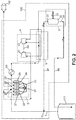
- FIGS 1 to 3 illustrate three possible implementations of the invention.
- the gas source 101 may comprise a tank or several tanks (only one tank is represented in the figures) containing liquefied natural gas, from which originates boil-off gas.
- Such gas tank(s) may be arranged on-board a liquefied natural gas carrier vessel, for example.
- the gas which is processed by a system according to the invention may be the boil-off gas, but it may be also vaporized liquid of natural gas, or a combination of boil-off gas and vaporized liquid of natural gas.
- This gas processed by the invention system may be comprised of more than 80% in-weight of methane.
- the gas intake 1 may be connected for receiving the boil-off gas which originates from the liquefied natural gas, or the vaporized liquid of natural gas.
- the gas liquefying system 100 comprises the liquid piston gas multistage compressor 2, the gas expansion device 3, the return gas duct 97, and optionally at least one of the following additional components: the turbo-compressor 4, the multi-stream heat exchanger 5, the gas cooler 60, the pre-compressor 80, the pump for liquefied gas 98, and control valves arranged on the return gas duct 97 and return liquid duct 99.
- the liquid piston gas multistage compressor 2 comprises several compressor stages 21-23 or 21-25 which are serially connected in a chain, so that each compressor stage processes gas outputted by the compressor stage just before in the chain, except the compressor stage 21 which processes gas originating from the gas intake 1.
- compressor stage 21 is the first one in the chain
- compressor stage 23 in figure 1 , or 25 in figures 2 and 3 is the last one in the chain.
- Each one of the compressor stages comprises a respective sealed cylinder which is connected for admitting a variable amount of driving liquid, and also comprises a liquid high-pressure supply device which varies the amount of driving liquid contained in the cylinder.
- the structure of such liquid piston compressor stage is well known, so that it is not necessary to repeat it here.
- the liquid high-pressure supply device of each one of the compressor stages comprises respective regulation means and a source of high-pressure driving liquid.
- the source of high-pressure driving liquid may be advantageously shared between the compressor stages, according to reference number 27.
- the ratio between output gas pressure and intake gas pressure individually for each compressor stage may be between two and fifteen.
- the regulation means allow easy and real-time adjustment of the capacity of the corresponding compressor stage.
- a fixed amount of an additional liquid is further provided for producing peripheral sealing between the dummy piston and the inner surface of the cylinder.
- This amount of additional liquid remains comprised between the peripheral surface of the dummy piston and the inner surface of the cylinder whatever the instant level of the driving liquid by moving together with the dummy piston.
- This additional liquid is selected for not producing polluting vapours and so that the gas to be compressed does not dissolve into it and does not produce any chemical reaction with it.
- Liquid of ionic type have been implemented for this purpose, or any other liquid capable of producing the functions of gas-sealing and lubricating.
- Intercooler devices may be arranged at the intermediate gas ducts 28 between two compressor stages which are successive in the chain of the liquid piston gas multistage gas compressor 2, and between the last compressor stage of the chain and the gas expansion device 3. In this way, the gas flowing within each intermediate gas duct 28 and to the gas expansion device 3 can be cooled down.
- the liquid piston gas multistage compressor 2 runs a near-isothermal process which minimizes energy lost to heat generation in comparison with a conventional reciprocating compressor.
- the figures only represent such gas cooler device at the gas outlet of the last compressor stage 23 or 25, with reference number 60.
- One of the compressor stages 21-23 or 21-25 outputs compressed gas to the gas expansion device 3.
- the gas expansion device 3 may comprise the expansion valve 31 and the flash drum 32. This latter is provided with the gas outlet 33 for discharging the expanded gas, and also with the liquid outlet 34 for discharging the liquefied gas which is produced by the gas expansion device 3.
- the compressed gas originating from the liquid piston gas multistage compressor 2 and possibly further compressed by centrifugal booster 41 is admitted into the flash drum 32 through the expansion valve 31.
- the expanded gas is driven to the duct node 10 for being recycled, through the return gas duct 97.
- the liquefied gas may be driven back to the gas source 101 if this latter is comprised of at least one tank of liquefied gas, through the return liquid duct 99.
- the return liquid duct 99 may be provided with the liquefied gas pump 98 or not, and also possibly with a by-pass for temporarily avoiding such pump.
- the liquefied gas may be thus delivered back to the liquid tank of the gas source 101, with a pressure of about 3.5 bara and a temperature between - 140°C and -150°C.
- the turbo-compressor 4 may be arranged between the gas expansion device 3 and the end gas outlet 29 of the liquid piston gas multistage compressor 2, from which said gas expansion device 3 is fed with compressed gas.
- the turbo-compressor 4 is arranged for compressing the gas delivered to the gas expansion device 3 in addition to compression by the liquid piston gas multistage compressor 2 before delivery of this compressed gas to the gas expansion device 3.
- the turbo-compressor 4 may comprise the centrifugal type booster 41, the radial inflow gas expander 42, the driving shaft 43 and the gas cooler 44.
- the booster 41 further compresses the compressed gas originating from the liquid piston gas multistage compressor 2, and part of the resulting compressed gas may be inputted into the expander 42 for driving in rotation the booster 41 through the shaft 43. Then, the expanded gas from the expander 42 may be driven back to node 10 through a dedicated gas duct for recycling.
- the gas cooler 44 may be arranged at the output of the booster 41 for a first stage in cooling down the resulting compressed gas.
- the heat exchanger 5 produces a second stage in the cooling down of the compressed gas which is delivered to the gas expansion device 3. It may be arranged for transferring heat from the compressed gas which is delivered to the gas expansion device 3, to the expanded gas which is produced by this latter.
- the heat exchanger 5 may be of multi-stream type, so as to transfer additionally heat from the expanded gas outputted by the expander 42 to the expanded gas which is produced by the gas expansion device 3.
- the heat exchanger 5 may be alternatively of several types known in the art.
- At least some of the compressor stages of the liquid piston gas multistage compressor 2 of the gas liquefying system 100 may also be used for supplying compressed gas to an extra gas-fed device.
- gas-fed device may be any, for example a gas burner, or an electrical power generator, or a gas-fuelled engine, namely an engine to be supplied only with gas as fuel, or a hybrid fuel engine.
- the engine may be a propulsion engine of a liquefied gas carrier vessel, equipped with the system 100 for re-liquefying boil-off gas.
- the gas-fuelled engine 102 is gas-fed from the end gas outlet 29 of the liquid piston gas multistage compressor 2, in parallel with the assembly of the turbo-compressor 4, the heat exchanger 5 and the gas expansion device 3.
- the compressed gas is preferably cooled down to temperature of about 40°C to 45°C by the gas cooler 44.
- Similar arrangement may be implemented for supplying gas to an engine which has pressure requirement at the fuel gas intake of this engine, in the range of 6 ⁇ 1.5 bara.
- the second implementation example represented in figure 2 is suitable again for supplying compressed gas within the pressure range of 16 ⁇ 4 bara to the engine 102, but the input pressure for the gas which is delivered to the assembly of the turbo-compressor 4, the heat exchanger 5 and the gas expansion device 3 is increased, for example to about 40 bara. This allows obtaining a liquefaction yield at the gas expansion device 3 which is higher.
- the compressor stages 24 and 25 are added in the liquid piston gas multistage compressor 2 with respect to figure 1 .
- the engine 102 is gas-supplied again from the gas outlet of the compressor stage 23, but this gas outlet being now an intermediate gas outlet of the chain of the compressor stages, situated at the intermediate gas duct 28 between the compressor stages 23 and 24.
- the booster 41 is no longer used for the gas fed into the gas expansion device 3, but for additionally compressing the gas issuing from the radial inflow gas expander 42, after this gas has been warmed in the heat exchanger 5, and then re-injecting it at an intermediate gas duct 28 of the chain of the compressor stages of the liquid piston gas multistage compressor 2.
- the booster 41 can be replaced by any expander braking device like an oil pump or a gear driven electrical generator. In the example represented, re-injection is carried out at the intermediate gas duct 28 between the compressor stages 22 and 23.
- no liquid pump may be required for directing the liquefied gas from the liquid outlet 34 of the flash drum 32 to the gas source 101, because the pressure in the flash drum 32 is high enough for handling the flow of liquefied gas only through a control valve in the return liquid duck 99.
- the third implementation example represented in figure 3 is suitable for supplying compressed gas within the pressure range of 100 bara to 450 bara to the engine 102'.
- the liquid piston gas multistage compressor 2 may have five compressor stages again, but the engine 102' is fed with compressed gas from the end gas outlet 29, after compressor stage 25.
- the gas cooler 60 may be arranged on the path between the end gas outlet 29 and the fuel gas intake of the engine 102'.
- the pre-compressor 80 may be arranged on the gas path between the gas intake 1 and the first compressor stage 21 of the liquid piston gas multistage gas compressor 2.
- the pre-compressor 80 may increase the gas pressure from atmospheric pressure value to between 5 bara and 10 bara.
- the gas expansion device 3 may then be supplied with compressed gas originating from the intermediate gas duct 28 which is situated between the compressor stages 23 and 24.
- the turbo-compressor 4 and the heat exchanger 5 may be implemented for the gas which is supplied by the liquid piston gas multistage gas compressor 2 to the gas expansion device 3 in a manner similar to that of the first implementation example of figure 1 , but without the gas cooler 60 acting on the gas to be liquefied.
- the expanded gas originating from the radial inflow gas expander 42 may be re-injected in the piston gas multistage gas compressor 2 at the intermediate gas duct 28 which is situated between the compressor stages 22 and 23.
- the actual fuel gas intake pressure may vary as a function of the engine load. But using a compressor which is based on liquid pistons allows easy control of the fuel gas intake pressure without gas recycling. This can save significant power amount.
- liquid piston technology allows supplying fuel gas to engines which have very different requirements for the gas pressure at their fuel gas intakes, while sharing the gas compressor with a gas liquefying system. Only the number of compressor stages is to be adapted. As a result, a shipyard can have a practical and standardized design for the combined gas liquefying system and fuel gas supply system, whatever the vessel propulsion engine type.
- the invention may be reproduced while adapting some implementation details with respect from the description hereabove provided with reference to the figures.
- the invention may be implemented whatever the number of compressor stages within the liquid piston gas multistage compressor, and whatever the position of the gas outlet along the chain of the compressor stages which supplies the gas expansion device with compressed gas.
- the numeral values which have been cited for the gas pressures have only been provided for illustrative purpose.
- the invention system may be used for supplying compressed gas to a gas-fed device having limited gas consumption, whereas the gas, for example boil-off gas, may exist initially in excess with respect to the consumption of the gas-fed device.
- the gas liquefying system of the invention allows recycling the excess of boil-off gas without gas loss and with minimum additional components and minimum energy consumption.
Claims (15)
- System (100) zur Verflüssigung eines Gases, umfassend:- eine Gasaufnahme (1) zum Verbinden mit einer Gasquelle (101);- mindestens einen Gaskompressor, der so verbunden ist, dass er mit Gas aus der Gasaufnahme gespeist wird;- eine Gasexpansionsvorrichtung (3), die so verbunden ist, dass sie mit komprimiertem Gas gespeist wird, das durch den mindestens einen Gaskompressor produziert wird, und eingerichtet ist, um sowohl verflüssigtes Gas als auch expandiertes Gas aus dem komprimierten Gas zu produzieren; und- einen Rückkanal (97), der so verbunden ist, dass das expandierte Gas aus einem Gasauslass (33) der Gasexpansionsvorrichtung (3) zu einem Kanalknoten (10) getrieben wird, der sich zwischen der Gasaufnahme (1) und dem mindestens einen Kompressor befindet,dadurch gekennzeichnet, dass der mindestens eine Gaskompressor einen mehrstufigen Kolbenkompressor für Flüssiggas (2) mit mindestens zwei Kompressorstufen (21-23; 21-25) umfasst, die in Reihe in einer geordneten Kette zwischen der Gasaufnahme (1) und einem Endgasauslass (29) verbunden sind, wobei jede Kompressorstufe mindestens einen Zylinder, der mit Antriebsflüssigkeit versorgt wird, einen Ausgleichkolben zwischen der Antriebsflüssigkeit und dem Gas, welches komprimiert wird, und auch eine Flüssighochdruckzufuhrvorrichtung umfasst, die angeordnet ist, um alternierend eine in dem Zylinder enthaltene Menge an Antriebsflüssigkeit zu erhöhen und zu verringern, um so Gas in der Kompressorstufe zu laden, zu komprimieren und abzugeben, wobei jede Kompressorstufe (22-23; 22-25), die von der ersten (21) in der Kette verschieden ist und als höhere Kompressorstufe bezeichnet wird, zur Verarbeitung von Gas verbunden ist, das durch eine vorhergehende Kompressorstufe, die sich in der Kette unmittelbar vor der höheren Kompressorstufe befindet, durch einen Zwischengaskanal (28) ausgegeben wird, der die vorhergehende Kompressorstufe mit der höheren Kompressorstufe verbindet, so dass der Druck des Gases, das aus der Gasaufnahme (1) fließt, mit jedem Mal, in dem es durch eine der Kompressorstufen verarbeitet wird, erhöht wird, und am Endgasauslass (29) ausgegebenes Gas nacheinander durch alle der Kompressorstufen der Kette verarbeitet worden ist, die Gasexpansionsvorrichtung (3) zur Annahme von komprimiertem Gas von dem Endgasauslass (29) des mehrstufigen Kolbenkompressors für Flüssiggas (2) oder von einem Zwischengasauslass verbunden ist, der sich an einem Zwischengaskanal (28) zwischen zwei Kompressorstufen (21-23; 21-25) befindet, die in der Kette aufeinander folgen.
- System nach einem der vorhergehenden Ansprüche, das eingerichtet ist, um sich an Bord eines Transportschiffs für Flüssiggas zu befinden, wobei die Gasaufnahme (1) vorgesehen ist, um zur Annahme von Abdampfgas verbunden zu werden, das aus Flüssiggas kommt, welches in Tanks enthalten ist, die an Bord des Schiffes angeordnet sind, wobei die Tanks mindestens einen Teil der Gasquelle (101) bilden, und ein Flüssigauslass (34) der Gasexpansionsvorrichtung (3) mit mindestens einem der Tanks verbunden ist, um das durch die Gasexpansionsvorrichtung produzierte Flüssiggas abzugeben.
- System nach Anspruch 1 oder 2, das zum Verarbeiten von Gas eingerichtet ist, das Methan, Ethan, Propan, Butan und Gemische davon enthält, einschließlich Erdgas und Erdölgas, insbesondere Gas, das aus mehr als 80 Gew.% Methan zusammengesetzt ist.
- System nach einem der vorhergehenden Ansprüche, das ferner zur Zuführung von komprimiertem Gas, das durch mindestens einige der Kompressorstufen (21-23; 21-25) des mehrstufigen Kolbenkompressors für Flüssiggas (2) verarbeitet worden ist, an eine Brenngasaufnahme eines Motors (102; 102') eingerichtet ist.
- System nach Anspruch 4 und Anspruch 2 oder 3, wobei der Motor (102; 102') ein Antriebsmotor des Schiffes ist.
- System nach Anspruch 5, das so eingerichtet ist, dass die Brenngasaufnahme des Antriebsmotors des Schiffes (102') mit komprimiertem Gas gespeist wird, das aus dem Endgasauslass (29) des mehrstufigen Kolbenkompressors für Flüssiggas (2) kommt, wobei an der Brenngasaufnahme des Antriebsmotors des Schiffes ein Gasdruck vorhanden ist, der im Bereich von 100 bar absolut bis 450 bar absolut liegt.
- System nach Anspruch 6, ferner umfassend einen Vorkompressor (80), der auf einem Gaspfad zwischen der Gasaufnahme (1) und der ersten Kompressorstufe (21) des mehrstufigen Kolbenkompressors für Flüssiggas (2) angeordnet ist.
- System nach Anspruch 5, das so eingerichtet ist, dass die Brenngasaufnahme des Antriebsmotors des Schiffes (102) mit komprimiertem Gas gespeist wird, das aus einem Zwischengasauslass kommt, der sich an einem Zwischengaskanal (28) zwischen zwei Kompressorstufen (21-23; 21-25) befindet, die in der Kette des mehrstufigen Kolbenkompressors für Flüssiggas (2) aufeinander folgen, wobei ein Gasdruck, der an der Brenngasaufnahme des Antriebsmotors des Schiffes vorliegt, im Bereich von 6 ± 1,5 bar absolut oder 16 ± 4 bar absolut liegt, und wobei die Gasexpansionsvorrichtung (3) mit komprimiertem Gas gespeist wird, das aus dem Endgasauslass (29) des mehrstufigen Kolbenkompressors für Flüssiggas kommt.
- System nach einem der vorhergehenden Ansprüche, wobei die Kette des mehrstufigen Kolbenkompressors für Flüssiggas (2) zwischen zwei und sechs Kompressorstufen (21-23; 21-25) umfasst, einschließlich der Werte zwei und sechs.
- System nach einem der vorhergehenden Ansprüche, das ferner Zwischenkühlvorrichtungen umfasst, die an den Zwischengaskanälen (28) zwischen zwei Kompressorstufen (21-23; 21-25), die in der Kette des mehrstufigen Kolbenkompressors für Flüssiggas (2) aufeinander folgen, und zwischen der letzten Kompressorstufe (23; 25) der Kette und der Gasexpansionsvorrichtung (3) angeordnet sind, um das Gas herunterzukühlen, welches in dem Zwischengaskanal und zu der Gasexpansionsvorrichtung fließt.
- System nach einem der vorhergehenden Ansprüche, wobei die Gasexpansionsvorrichtung (3) ein Expansionsventil (31) und eine Flash-Trommel (32) umfasst, die mit dem Gasauslass (33), um das expandierte Gas abzugeben, und mit einem Flüssigauslass (34) ausgestattet ist, um das Flüssiggas abzugeben, die durch die Gasexpansionsvorrichtung produziert wurden, wobei das durch den Gaskompressor produzierte komprimierte Gas durch das Expansionsventil in die Flash-Trommel eingelassen wird.
- System nach einem der vorhergehenden Ansprüche, ferner umfassend einen Turbokompressor (4), der zwischen der Gasexpansionsvorrichtung (3) und dem Endgasauslass (29) des mehrstufigen Kolbenkompressors für Flüssiggas (2) oder dem Zwischengasauslass (28) angeordnet ist, aus dem die Gasexpansionsvorrichtung mit komprimiertem Gas gespeist wird, wobei der Turbokompressor angeordnet ist, um das der Gasexpansionsvorrichtung (3) zugeführte komprimierte Gas zusätzlich zu der Kompression durch den mehrstufigen Kolbenkompressor für Flüssiggas zu komprimieren, bevor das komprimierte Gas der Gasexpansionsvorrichtung zugeführt wird.
- System nach einem der vorhergehenden Ansprüche, ferner umfassend einen Wärmetauscher (5), der zum Übertragen von Wärme aus dem komprimierten Gas, das der Gasexpansionsvorrichtung (3) zugeführt wird, an das expandierte Gas angeordnet ist, das durch die Gasexpansionsvorrichtung produziert wird.
- Transportschiff für Flüssiggas, umfassend mindestens einen Flüssiggastank an Bord des Schiffes, und auch umfassend ein System (100) zum Verflüssigen von Gas gemäß einem der vorhergehenden Ansprüche, wobei die Gasaufnahme (1) des Systems zur Annahme von Abdampfgas verbunden ist, das aus dem mindestens einen Flüssiggastank kommt, und ein Flüssigauslass (34) der Gasexpansionsvorrichtung (3) mit mindestens einem Flüssiggastank verbunden ist, um das durch die Gasexpansionsvorrichtung produzierte Flüssiggas abzugeben.
- Transportschiff für Flüssiggas nach Anspruch 14, ferner umfassend einen gasbetriebenen Antriebsmotor des Schiffes oder einen Hybridbrennstoff-Antriebsmotor des Schiffes (102; 102'), und wobei die Kette der Kompressorstufen (21-23; 21-25) des mehrstufigen Kolbenkompressors für Flüssiggas (2) mit mindestens einem Gasauslass zum Ausgeben von Gas ausgestattet ist, das durch mindestens eine der Kompressorstufen verarbeitet worden ist, und wobei der Gasauslass mit einer Gasbrennstoffaufnahme des Motors verbunden ist.
Priority Applications (9)
| Application Number | Priority Date | Filing Date | Title |
|---|---|---|---|
| ES16305044T ES2743317T3 (es) | 2016-01-18 | 2016-01-18 | Sistema para licuar un gas |
| EP16305044.6A EP3193113B1 (de) | 2016-01-18 | 2016-01-18 | System zur verflüssigung eines gases |
| PCT/EP2017/050351 WO2017125275A1 (en) | 2016-01-18 | 2017-01-09 | System for liquefying a gas |
| JP2018555828A JP2019505749A (ja) | 2016-01-18 | 2017-01-09 | ガスを液化するためのシステム |
| CN201780018299.5A CN109312980B (zh) | 2016-01-18 | 2017-01-09 | 用于使气体液化的系统 |
| KR1020187023583A KR20180108667A (ko) | 2016-01-18 | 2017-01-09 | 가스 액화 시스템 |
| RU2018128027A RU2718108C2 (ru) | 2016-01-18 | 2017-01-09 | Система для сжижения газа |
| US16/070,880 US10801775B2 (en) | 2016-01-18 | 2017-01-09 | System for liquefying a gas |
| HRP20191448 HRP20191448T1 (hr) | 2016-01-18 | 2019-08-09 | Sustav za ukapljivanje plina |
Applications Claiming Priority (1)
| Application Number | Priority Date | Filing Date | Title |
|---|---|---|---|
| EP16305044.6A EP3193113B1 (de) | 2016-01-18 | 2016-01-18 | System zur verflüssigung eines gases |
Publications (2)
| Publication Number | Publication Date |
|---|---|
| EP3193113A1 EP3193113A1 (de) | 2017-07-19 |
| EP3193113B1 true EP3193113B1 (de) | 2019-05-29 |
Family
ID=55405287
Family Applications (1)
| Application Number | Title | Priority Date | Filing Date |
|---|---|---|---|
| EP16305044.6A Active EP3193113B1 (de) | 2016-01-18 | 2016-01-18 | System zur verflüssigung eines gases |
Country Status (9)
| Country | Link |
|---|---|
| US (1) | US10801775B2 (de) |
| EP (1) | EP3193113B1 (de) |
| JP (1) | JP2019505749A (de) |
| KR (1) | KR20180108667A (de) |
| CN (1) | CN109312980B (de) |
| ES (1) | ES2743317T3 (de) |
| HR (1) | HRP20191448T1 (de) |
| RU (1) | RU2718108C2 (de) |
| WO (1) | WO2017125275A1 (de) |
Families Citing this family (7)
| Publication number | Priority date | Publication date | Assignee | Title |
|---|---|---|---|---|
| WO2017145769A1 (ja) * | 2016-02-23 | 2017-08-31 | 株式会社日立プラントメカニクス | 高圧水素の膨張タービン・コンプレッサ式充填システム及びその制御方法 |
| US11906224B2 (en) | 2017-08-31 | 2024-02-20 | Energy Internet Corporation | Controlled refrigeration and liquefaction using compatible materials for energy management |
| US11566839B2 (en) | 2017-08-31 | 2023-01-31 | Energy Internet Corporation | Controlled liquefaction and energy management |
| US11261107B2 (en) | 2017-08-31 | 2022-03-01 | Energy Internet Corporation | Desalination using pressure vessels |
| SG10201802888QA (en) * | 2018-01-24 | 2019-08-27 | Gas Tech Development Pte Ltd | Process and system for reliquefying boil-off gas (bog) |
| RU2702441C1 (ru) * | 2018-05-10 | 2019-10-08 | Общество с ограниченной ответственностью "Газ Хим Технолоджи" | Комплекс по переработке и сжижению природного газа (варианты) |
| IT202100010460A1 (it) * | 2021-04-26 | 2022-10-26 | Nuovo Pignone Tecnologie Srl | Hydrogen compressing assembly, hydrogen production plant, and compressing method. |
Citations (1)
| Publication number | Priority date | Publication date | Assignee | Title |
|---|---|---|---|---|
| US20120134851A1 (en) * | 2009-05-12 | 2012-05-31 | Robert Adler | Compressor comprising a piston dummy |
Family Cites Families (16)
| Publication number | Priority date | Publication date | Assignee | Title |
|---|---|---|---|---|
| CH561620A5 (de) * | 1972-12-11 | 1975-05-15 | Sulzer Ag | |
| SK144994A3 (en) | 1992-05-29 | 1995-05-10 | Nat Power Plc | Gas compressor |
| US5863186A (en) * | 1996-10-15 | 1999-01-26 | Green; John S. | Method for compressing gases using a multi-stage hydraulically-driven compressor |
| US6062828A (en) * | 1998-06-04 | 2000-05-16 | Raytheon Company | Compressor for liquefied gas applications |
| BR0108083B1 (pt) * | 2000-02-03 | 2009-08-11 | sistema de recuperação de vapor que usa compressor guiado por turbo-expansor. | |
| NO314423B1 (no) * | 2001-07-31 | 2003-03-17 | Hamworthy Kse As | Fremgangsmåte ved gjenvinning av VOC-gass og anlegg for gjenvinning av VOC-gass |
| GB0400986D0 (en) * | 2004-01-16 | 2004-02-18 | Cryostar France Sa | Compressor |
| JP2005273681A (ja) * | 2004-03-22 | 2005-10-06 | Ebara Corp | 低温液化ガス貯留システム |
| US7488159B2 (en) * | 2004-06-25 | 2009-02-10 | Air Products And Chemicals, Inc. | Zero-clearance ultra-high-pressure gas compressor |
| DE102010053091A1 (de) * | 2010-12-01 | 2012-06-06 | Linde Aktiengesellschaft | Mehrstufiger Kolbenverdichter |
| KR101106088B1 (ko) * | 2011-03-22 | 2012-01-18 | 대우조선해양 주식회사 | 고압 천연가스 분사 엔진용 연료 공급 시스템의 재액화 장치에 사용되는 비폭발성 혼합냉매 |
| JP2013087911A (ja) * | 2011-10-20 | 2013-05-13 | Mitsubishi Heavy Ind Ltd | 貯蔵槽の圧力上昇抑制装置、これを備えた圧力上昇抑制システム、この抑制方法、これを備えた液化ガス運搬船およびこれを備えた液化ガス貯蔵設備 |
| KR101386543B1 (ko) * | 2012-10-24 | 2014-04-18 | 대우조선해양 주식회사 | 선박의 증발가스 처리 시스템 |
| KR101350807B1 (ko) * | 2012-10-24 | 2014-01-16 | 대우조선해양 주식회사 | 선박용 엔진의 하이브리드 연료공급 시스템 |
| JP6151039B2 (ja) * | 2013-02-12 | 2017-06-21 | 三菱重工業株式会社 | 液化石油ガス運搬船、再液化装置、ボイルオフガスの再液化方法 |
| KR101640765B1 (ko) * | 2013-06-26 | 2016-07-19 | 대우조선해양 주식회사 | 선박의 증발가스 처리 시스템 및 방법 |
-
2016
- 2016-01-18 ES ES16305044T patent/ES2743317T3/es active Active
- 2016-01-18 EP EP16305044.6A patent/EP3193113B1/de active Active
-
2017
- 2017-01-09 WO PCT/EP2017/050351 patent/WO2017125275A1/en active Application Filing
- 2017-01-09 US US16/070,880 patent/US10801775B2/en active Active
- 2017-01-09 KR KR1020187023583A patent/KR20180108667A/ko not_active Application Discontinuation
- 2017-01-09 RU RU2018128027A patent/RU2718108C2/ru active
- 2017-01-09 JP JP2018555828A patent/JP2019505749A/ja active Pending
- 2017-01-09 CN CN201780018299.5A patent/CN109312980B/zh active Active
-
2019
- 2019-08-09 HR HRP20191448 patent/HRP20191448T1/hr unknown
Patent Citations (1)
| Publication number | Priority date | Publication date | Assignee | Title |
|---|---|---|---|---|
| US20120134851A1 (en) * | 2009-05-12 | 2012-05-31 | Robert Adler | Compressor comprising a piston dummy |
Also Published As
| Publication number | Publication date |
|---|---|
| CN109312980B (zh) | 2021-07-02 |
| RU2018128027A3 (de) | 2020-03-03 |
| EP3193113A1 (de) | 2017-07-19 |
| CN109312980A (zh) | 2019-02-05 |
| US20190056174A1 (en) | 2019-02-21 |
| US10801775B2 (en) | 2020-10-13 |
| HRP20191448T1 (hr) | 2019-11-15 |
| KR20180108667A (ko) | 2018-10-04 |
| RU2018128027A (ru) | 2020-02-20 |
| RU2718108C2 (ru) | 2020-03-30 |
| JP2019505749A (ja) | 2019-02-28 |
| WO2017125275A1 (en) | 2017-07-27 |
| ES2743317T3 (es) | 2020-02-18 |
Similar Documents
| Publication | Publication Date | Title |
|---|---|---|
| EP3193113B1 (de) | System zur verflüssigung eines gases | |
| US10563621B2 (en) | System for supplying compressed gas to several gas-fed devices | |
| JP6935538B2 (ja) | 天然ガス燃料の供給装置および方法 | |
| US11749818B2 (en) | Multi-stage turbocharging compressor for fuel cell systems | |
| CN104727982B (zh) | 燃气发动机 | |
| JP6831394B2 (ja) | 気化ガスを圧縮する装置および方法 | |
| PL85439B1 (de) | ||
| JP6524485B2 (ja) | ボイルオフガス利用システム | |
| CN111480029B (zh) | 在可变抽吸条件下将加压气体提供给消耗装置的方法和对应的压缩机装置 | |
| US20130097994A1 (en) | Multi-fluid turbine engine | |
| CN108367799A (zh) | 包括发动机的轮船 | |
| GB1573193A (en) | Reciprocating piston internal combustion engine and turbocharger assembly | |
| WO2017129373A1 (en) | Compressor | |
| RU182784U1 (ru) | Система подачи криогенной жидкости | |
| JP2024505845A (ja) | モジュール式圧縮装置及び方法 | |
| GB2618053A (en) | Power generation and storage | |
| WO2013083156A1 (en) | Scavenging system |
Legal Events
| Date | Code | Title | Description |
|---|---|---|---|
| PUAI | Public reference made under article 153(3) epc to a published international application that has entered the european phase |
Free format text: ORIGINAL CODE: 0009012 |
|
| STAA | Information on the status of an ep patent application or granted ep patent |
Free format text: STATUS: THE APPLICATION HAS BEEN PUBLISHED |
|
| AK | Designated contracting states |
Kind code of ref document: A1 Designated state(s): AL AT BE BG CH CY CZ DE DK EE ES FI FR GB GR HR HU IE IS IT LI LT LU LV MC MK MT NL NO PL PT RO RS SE SI SK SM TR |
|
| AX | Request for extension of the european patent |
Extension state: BA ME |
|
| STAA | Information on the status of an ep patent application or granted ep patent |
Free format text: STATUS: REQUEST FOR EXAMINATION WAS MADE |
|
| 17P | Request for examination filed |
Effective date: 20180119 |
|
| RBV | Designated contracting states (corrected) |
Designated state(s): AL AT BE BG CH CY CZ DE DK EE ES FI FR GB GR HR HU IE IS IT LI LT LU LV MC MK MT NL NO PL PT RO RS SE SI SK SM TR |
|
| GRAP | Despatch of communication of intention to grant a patent |
Free format text: ORIGINAL CODE: EPIDOSNIGR1 |
|
| STAA | Information on the status of an ep patent application or granted ep patent |
Free format text: STATUS: GRANT OF PATENT IS INTENDED |
|
| INTG | Intention to grant announced |
Effective date: 20190222 |
|
| GRAS | Grant fee paid |
Free format text: ORIGINAL CODE: EPIDOSNIGR3 |
|
| GRAA | (expected) grant |
Free format text: ORIGINAL CODE: 0009210 |
|
| STAA | Information on the status of an ep patent application or granted ep patent |
Free format text: STATUS: THE PATENT HAS BEEN GRANTED |
|
| AK | Designated contracting states |
Kind code of ref document: B1 Designated state(s): AL AT BE BG CH CY CZ DE DK EE ES FI FR GB GR HR HU IE IS IT LI LT LU LV MC MK MT NL NO PL PT RO RS SE SI SK SM TR |
|
| REG | Reference to a national code |
Ref country code: GB Ref legal event code: FG4D |
|
| REG | Reference to a national code |
Ref country code: CH Ref legal event code: EP |
|
| REG | Reference to a national code |
Ref country code: AT Ref legal event code: REF Ref document number: 1138509 Country of ref document: AT Kind code of ref document: T Effective date: 20190615 |
|
| REG | Reference to a national code |
Ref country code: DE Ref legal event code: R096 Ref document number: 602016014549 Country of ref document: DE |
|
| REG | Reference to a national code |
Ref country code: IE Ref legal event code: FG4D |
|
| REG | Reference to a national code |
Ref country code: HR Ref legal event code: TUEP Ref document number: P20191448T Country of ref document: HR |
|
| REG | Reference to a national code |
Ref country code: NL Ref legal event code: FP |
|
| REG | Reference to a national code |
Ref country code: SE Ref legal event code: TRGR |
|
| REG | Reference to a national code |
Ref country code: LT Ref legal event code: MG4D |
|
| REG | Reference to a national code |
Ref country code: NO Ref legal event code: T2 Effective date: 20190529 |
|
| PG25 | Lapsed in a contracting state [announced via postgrant information from national office to epo] |
Ref country code: AL Free format text: LAPSE BECAUSE OF FAILURE TO SUBMIT A TRANSLATION OF THE DESCRIPTION OR TO PAY THE FEE WITHIN THE PRESCRIBED TIME-LIMIT Effective date: 20190529 Ref country code: PT Free format text: LAPSE BECAUSE OF FAILURE TO SUBMIT A TRANSLATION OF THE DESCRIPTION OR TO PAY THE FEE WITHIN THE PRESCRIBED TIME-LIMIT Effective date: 20190930 Ref country code: LT Free format text: LAPSE BECAUSE OF FAILURE TO SUBMIT A TRANSLATION OF THE DESCRIPTION OR TO PAY THE FEE WITHIN THE PRESCRIBED TIME-LIMIT Effective date: 20190529 |
|
| REG | Reference to a national code |
Ref country code: HR Ref legal event code: T1PR Ref document number: P20191448 Country of ref document: HR |
|
| PG25 | Lapsed in a contracting state [announced via postgrant information from national office to epo] |
Ref country code: RS Free format text: LAPSE BECAUSE OF FAILURE TO SUBMIT A TRANSLATION OF THE DESCRIPTION OR TO PAY THE FEE WITHIN THE PRESCRIBED TIME-LIMIT Effective date: 20190529 Ref country code: LV Free format text: LAPSE BECAUSE OF FAILURE TO SUBMIT A TRANSLATION OF THE DESCRIPTION OR TO PAY THE FEE WITHIN THE PRESCRIBED TIME-LIMIT Effective date: 20190529 Ref country code: GR Free format text: LAPSE BECAUSE OF FAILURE TO SUBMIT A TRANSLATION OF THE DESCRIPTION OR TO PAY THE FEE WITHIN THE PRESCRIBED TIME-LIMIT Effective date: 20190830 Ref country code: BG Free format text: LAPSE BECAUSE OF FAILURE TO SUBMIT A TRANSLATION OF THE DESCRIPTION OR TO PAY THE FEE WITHIN THE PRESCRIBED TIME-LIMIT Effective date: 20190829 |
|
| REG | Reference to a national code |
Ref country code: AT Ref legal event code: MK05 Ref document number: 1138509 Country of ref document: AT Kind code of ref document: T Effective date: 20190529 |
|
| REG | Reference to a national code |
Ref country code: HR Ref legal event code: ODRP Ref document number: P20191448 Country of ref document: HR Payment date: 20200109 Year of fee payment: 5 |
|
| PG25 | Lapsed in a contracting state [announced via postgrant information from national office to epo] |
Ref country code: AT Free format text: LAPSE BECAUSE OF FAILURE TO SUBMIT A TRANSLATION OF THE DESCRIPTION OR TO PAY THE FEE WITHIN THE PRESCRIBED TIME-LIMIT Effective date: 20190529 Ref country code: RO Free format text: LAPSE BECAUSE OF FAILURE TO SUBMIT A TRANSLATION OF THE DESCRIPTION OR TO PAY THE FEE WITHIN THE PRESCRIBED TIME-LIMIT Effective date: 20190529 Ref country code: CZ Free format text: LAPSE BECAUSE OF FAILURE TO SUBMIT A TRANSLATION OF THE DESCRIPTION OR TO PAY THE FEE WITHIN THE PRESCRIBED TIME-LIMIT Effective date: 20190529 Ref country code: SK Free format text: LAPSE BECAUSE OF FAILURE TO SUBMIT A TRANSLATION OF THE DESCRIPTION OR TO PAY THE FEE WITHIN THE PRESCRIBED TIME-LIMIT Effective date: 20190529 Ref country code: EE Free format text: LAPSE BECAUSE OF FAILURE TO SUBMIT A TRANSLATION OF THE DESCRIPTION OR TO PAY THE FEE WITHIN THE PRESCRIBED TIME-LIMIT Effective date: 20190529 Ref country code: DK Free format text: LAPSE BECAUSE OF FAILURE TO SUBMIT A TRANSLATION OF THE DESCRIPTION OR TO PAY THE FEE WITHIN THE PRESCRIBED TIME-LIMIT Effective date: 20190529 |
|
| REG | Reference to a national code |
Ref country code: ES Ref legal event code: FG2A Ref document number: 2743317 Country of ref document: ES Kind code of ref document: T3 Effective date: 20200218 |
|
| PG25 | Lapsed in a contracting state [announced via postgrant information from national office to epo] |
Ref country code: SM Free format text: LAPSE BECAUSE OF FAILURE TO SUBMIT A TRANSLATION OF THE DESCRIPTION OR TO PAY THE FEE WITHIN THE PRESCRIBED TIME-LIMIT Effective date: 20190529 |
|
| REG | Reference to a national code |
Ref country code: DE Ref legal event code: R097 Ref document number: 602016014549 Country of ref document: DE |
|
| PLBE | No opposition filed within time limit |
Free format text: ORIGINAL CODE: 0009261 |
|
| STAA | Information on the status of an ep patent application or granted ep patent |
Free format text: STATUS: NO OPPOSITION FILED WITHIN TIME LIMIT |
|
| PG25 | Lapsed in a contracting state [announced via postgrant information from national office to epo] |
Ref country code: PL Free format text: LAPSE BECAUSE OF FAILURE TO SUBMIT A TRANSLATION OF THE DESCRIPTION OR TO PAY THE FEE WITHIN THE PRESCRIBED TIME-LIMIT Effective date: 20190529 |
|
| 26N | No opposition filed |
Effective date: 20200303 |
|
| PG25 | Lapsed in a contracting state [announced via postgrant information from national office to epo] |
Ref country code: SI Free format text: LAPSE BECAUSE OF FAILURE TO SUBMIT A TRANSLATION OF THE DESCRIPTION OR TO PAY THE FEE WITHIN THE PRESCRIBED TIME-LIMIT Effective date: 20190529 |
|
| PG25 | Lapsed in a contracting state [announced via postgrant information from national office to epo] |
Ref country code: MC Free format text: LAPSE BECAUSE OF FAILURE TO SUBMIT A TRANSLATION OF THE DESCRIPTION OR TO PAY THE FEE WITHIN THE PRESCRIBED TIME-LIMIT Effective date: 20190529 |
|
| REG | Reference to a national code |
Ref country code: BE Ref legal event code: MM Effective date: 20200131 |
|
| PG25 | Lapsed in a contracting state [announced via postgrant information from national office to epo] |
Ref country code: LU Free format text: LAPSE BECAUSE OF NON-PAYMENT OF DUE FEES Effective date: 20200118 |
|
| PG25 | Lapsed in a contracting state [announced via postgrant information from national office to epo] |
Ref country code: BE Free format text: LAPSE BECAUSE OF NON-PAYMENT OF DUE FEES Effective date: 20200131 |
|
| REG | Reference to a national code |
Ref country code: HR Ref legal event code: ODRP Ref document number: P20191448 Country of ref document: HR Payment date: 20210108 Year of fee payment: 6 |
|
| PG25 | Lapsed in a contracting state [announced via postgrant information from national office to epo] |
Ref country code: IE Free format text: LAPSE BECAUSE OF NON-PAYMENT OF DUE FEES Effective date: 20200118 |
|
| REG | Reference to a national code |
Ref country code: HR Ref legal event code: ODRP Ref document number: P20191448 Country of ref document: HR Payment date: 20220112 Year of fee payment: 7 |
|
| PG25 | Lapsed in a contracting state [announced via postgrant information from national office to epo] |
Ref country code: MT Free format text: LAPSE BECAUSE OF FAILURE TO SUBMIT A TRANSLATION OF THE DESCRIPTION OR TO PAY THE FEE WITHIN THE PRESCRIBED TIME-LIMIT Effective date: 20190529 Ref country code: CY Free format text: LAPSE BECAUSE OF FAILURE TO SUBMIT A TRANSLATION OF THE DESCRIPTION OR TO PAY THE FEE WITHIN THE PRESCRIBED TIME-LIMIT Effective date: 20190529 |
|
| PG25 | Lapsed in a contracting state [announced via postgrant information from national office to epo] |
Ref country code: MK Free format text: LAPSE BECAUSE OF FAILURE TO SUBMIT A TRANSLATION OF THE DESCRIPTION OR TO PAY THE FEE WITHIN THE PRESCRIBED TIME-LIMIT Effective date: 20190529 Ref country code: IS Free format text: LAPSE BECAUSE OF FAILURE TO SUBMIT A TRANSLATION OF THE DESCRIPTION OR TO PAY THE FEE WITHIN THE PRESCRIBED TIME-LIMIT Effective date: 20190929 |
|
| REG | Reference to a national code |
Ref country code: HR Ref legal event code: ODRP Ref document number: P20191448 Country of ref document: HR Payment date: 20230112 Year of fee payment: 8 |
|
| PGFP | Annual fee paid to national office [announced via postgrant information from national office to epo] |
Ref country code: NO Payment date: 20230120 Year of fee payment: 8 Ref country code: FR Payment date: 20230123 Year of fee payment: 8 Ref country code: FI Payment date: 20230119 Year of fee payment: 8 Ref country code: ES Payment date: 20230216 Year of fee payment: 8 Ref country code: CH Payment date: 20230130 Year of fee payment: 8 |
|
| PGFP | Annual fee paid to national office [announced via postgrant information from national office to epo] |
Ref country code: TR Payment date: 20230117 Year of fee payment: 8 Ref country code: SE Payment date: 20230123 Year of fee payment: 8 Ref country code: IT Payment date: 20230131 Year of fee payment: 8 Ref country code: HR Payment date: 20230112 Year of fee payment: 8 Ref country code: GB Payment date: 20230124 Year of fee payment: 8 Ref country code: DE Payment date: 20230119 Year of fee payment: 8 |
|
| PGFP | Annual fee paid to national office [announced via postgrant information from national office to epo] |
Ref country code: NL Payment date: 20230124 Year of fee payment: 8 |
|
| PGFP | Annual fee paid to national office [announced via postgrant information from national office to epo] |
Ref country code: NL Payment date: 20240123 Year of fee payment: 9 |
|
| PGFP | Annual fee paid to national office [announced via postgrant information from national office to epo] |
Ref country code: ES Payment date: 20240216 Year of fee payment: 9 |