EP3192939B1 - Skirting board, decorative system and method for manufacturing a skirting board - Google Patents
Skirting board, decorative system and method for manufacturing a skirting board Download PDFInfo
- Publication number
- EP3192939B1 EP3192939B1 EP17150881.5A EP17150881A EP3192939B1 EP 3192939 B1 EP3192939 B1 EP 3192939B1 EP 17150881 A EP17150881 A EP 17150881A EP 3192939 B1 EP3192939 B1 EP 3192939B1
- Authority
- EP
- European Patent Office
- Prior art keywords
- core
- plate
- shaped material
- skirting board
- groove
- Prior art date
- Legal status (The legal status is an assumption and is not a legal conclusion. Google has not performed a legal analysis and makes no representation as to the accuracy of the status listed.)
- Active
Links
Images


Classifications
-
- B—PERFORMING OPERATIONS; TRANSPORTING
- B32—LAYERED PRODUCTS
- B32B—LAYERED PRODUCTS, i.e. PRODUCTS BUILT-UP OF STRATA OF FLAT OR NON-FLAT, e.g. CELLULAR OR HONEYCOMB, FORM
- B32B21/00—Layered products comprising a layer of wood, e.g. wood board, veneer, wood particle board
- B32B21/04—Layered products comprising a layer of wood, e.g. wood board, veneer, wood particle board comprising wood as the main or only constituent of a layer, which is next to another layer of the same or of a different material
- B32B21/08—Layered products comprising a layer of wood, e.g. wood board, veneer, wood particle board comprising wood as the main or only constituent of a layer, which is next to another layer of the same or of a different material of synthetic resin
-
- B—PERFORMING OPERATIONS; TRANSPORTING
- B32—LAYERED PRODUCTS
- B32B—LAYERED PRODUCTS, i.e. PRODUCTS BUILT-UP OF STRATA OF FLAT OR NON-FLAT, e.g. CELLULAR OR HONEYCOMB, FORM
- B32B21/00—Layered products comprising a layer of wood, e.g. wood board, veneer, wood particle board
- B32B21/02—Layered products comprising a layer of wood, e.g. wood board, veneer, wood particle board the layer being formed of fibres, chips, or particles, e.g. MDF, HDF, OSB, chipboard, particle board, hardboard
-
- B—PERFORMING OPERATIONS; TRANSPORTING
- B32—LAYERED PRODUCTS
- B32B—LAYERED PRODUCTS, i.e. PRODUCTS BUILT-UP OF STRATA OF FLAT OR NON-FLAT, e.g. CELLULAR OR HONEYCOMB, FORM
- B32B27/00—Layered products comprising a layer of synthetic resin
- B32B27/30—Layered products comprising a layer of synthetic resin comprising vinyl (co)polymers; comprising acrylic (co)polymers
-
- B—PERFORMING OPERATIONS; TRANSPORTING
- B32—LAYERED PRODUCTS
- B32B—LAYERED PRODUCTS, i.e. PRODUCTS BUILT-UP OF STRATA OF FLAT OR NON-FLAT, e.g. CELLULAR OR HONEYCOMB, FORM
- B32B3/00—Layered products comprising a layer with external or internal discontinuities or unevennesses, or a layer of non-planar shape; Layered products comprising a layer having particular features of form
- B32B3/26—Layered products comprising a layer with external or internal discontinuities or unevennesses, or a layer of non-planar shape; Layered products comprising a layer having particular features of form characterised by a particular shape of the outline of the cross-section of a continuous layer; characterised by a layer with cavities or internal voids ; characterised by an apertured layer
- B32B3/30—Layered products comprising a layer with external or internal discontinuities or unevennesses, or a layer of non-planar shape; Layered products comprising a layer having particular features of form characterised by a particular shape of the outline of the cross-section of a continuous layer; characterised by a layer with cavities or internal voids ; characterised by an apertured layer characterised by a layer formed with recesses or projections, e.g. hollows, grooves, protuberances, ribs
-
- B—PERFORMING OPERATIONS; TRANSPORTING
- B32—LAYERED PRODUCTS
- B32B—LAYERED PRODUCTS, i.e. PRODUCTS BUILT-UP OF STRATA OF FLAT OR NON-FLAT, e.g. CELLULAR OR HONEYCOMB, FORM
- B32B37/00—Methods or apparatus for laminating, e.g. by curing or by ultrasonic bonding
- B32B37/0076—Methods or apparatus for laminating, e.g. by curing or by ultrasonic bonding characterised in that the layers are not bonded on the totality of their surfaces
- B32B37/0084—Point bonding
-
- B—PERFORMING OPERATIONS; TRANSPORTING
- B32—LAYERED PRODUCTS
- B32B—LAYERED PRODUCTS, i.e. PRODUCTS BUILT-UP OF STRATA OF FLAT OR NON-FLAT, e.g. CELLULAR OR HONEYCOMB, FORM
- B32B7/00—Layered products characterised by the relation between layers; Layered products characterised by the relative orientation of features between layers, or by the relative values of a measurable parameter between layers, i.e. products comprising layers having different physical, chemical or physicochemical properties; Layered products characterised by the interconnection of layers
- B32B7/04—Interconnection of layers
- B32B7/05—Interconnection of layers the layers not being connected over the whole surface, e.g. discontinuous connection or patterned connection
-
- E—FIXED CONSTRUCTIONS
- E04—BUILDING
- E04F—FINISHING WORK ON BUILDINGS, e.g. STAIRS, FLOORS
- E04F19/00—Other details of constructional parts for finishing work on buildings
- E04F19/02—Borders; Finishing strips, e.g. beadings; Light coves
- E04F19/04—Borders; Finishing strips, e.g. beadings; Light coves for use between floor or ceiling and wall, e.g. skirtings
-
- B—PERFORMING OPERATIONS; TRANSPORTING
- B32—LAYERED PRODUCTS
- B32B—LAYERED PRODUCTS, i.e. PRODUCTS BUILT-UP OF STRATA OF FLAT OR NON-FLAT, e.g. CELLULAR OR HONEYCOMB, FORM
- B32B2317/00—Animal or vegetable based
- B32B2317/16—Wood, e.g. woodboard, fibreboard, woodchips
-
- B—PERFORMING OPERATIONS; TRANSPORTING
- B32—LAYERED PRODUCTS
- B32B—LAYERED PRODUCTS, i.e. PRODUCTS BUILT-UP OF STRATA OF FLAT OR NON-FLAT, e.g. CELLULAR OR HONEYCOMB, FORM
- B32B2327/00—Polyvinylhalogenides
- B32B2327/06—PVC, i.e. polyvinylchloride
-
- B—PERFORMING OPERATIONS; TRANSPORTING
- B32—LAYERED PRODUCTS
- B32B—LAYERED PRODUCTS, i.e. PRODUCTS BUILT-UP OF STRATA OF FLAT OR NON-FLAT, e.g. CELLULAR OR HONEYCOMB, FORM
- B32B2471/00—Floor coverings
-
- E—FIXED CONSTRUCTIONS
- E04—BUILDING
- E04F—FINISHING WORK ON BUILDINGS, e.g. STAIRS, FLOORS
- E04F19/00—Other details of constructional parts for finishing work on buildings
- E04F19/02—Borders; Finishing strips, e.g. beadings; Light coves
- E04F19/04—Borders; Finishing strips, e.g. beadings; Light coves for use between floor or ceiling and wall, e.g. skirtings
- E04F2019/0404—Borders; Finishing strips, e.g. beadings; Light coves for use between floor or ceiling and wall, e.g. skirtings characterised by the material
- E04F2019/0409—Borders; Finishing strips, e.g. beadings; Light coves for use between floor or ceiling and wall, e.g. skirtings characterised by the material of wood
-
- E—FIXED CONSTRUCTIONS
- E04—BUILDING
- E04F—FINISHING WORK ON BUILDINGS, e.g. STAIRS, FLOORS
- E04F19/00—Other details of constructional parts for finishing work on buildings
- E04F19/02—Borders; Finishing strips, e.g. beadings; Light coves
- E04F19/04—Borders; Finishing strips, e.g. beadings; Light coves for use between floor or ceiling and wall, e.g. skirtings
- E04F2019/0404—Borders; Finishing strips, e.g. beadings; Light coves for use between floor or ceiling and wall, e.g. skirtings characterised by the material
- E04F2019/0422—Borders; Finishing strips, e.g. beadings; Light coves for use between floor or ceiling and wall, e.g. skirtings characterised by the material of organic plastics with or without reinforcements or filling materials
- E04F2019/0427—Borders; Finishing strips, e.g. beadings; Light coves for use between floor or ceiling and wall, e.g. skirtings characterised by the material of organic plastics with or without reinforcements or filling materials with a integrally formed hinge
-
- E—FIXED CONSTRUCTIONS
- E04—BUILDING
- E04F—FINISHING WORK ON BUILDINGS, e.g. STAIRS, FLOORS
- E04F19/00—Other details of constructional parts for finishing work on buildings
- E04F19/02—Borders; Finishing strips, e.g. beadings; Light coves
- E04F19/04—Borders; Finishing strips, e.g. beadings; Light coves for use between floor or ceiling and wall, e.g. skirtings
- E04F2019/0404—Borders; Finishing strips, e.g. beadings; Light coves for use between floor or ceiling and wall, e.g. skirtings characterised by the material
- E04F2019/0431—Borders; Finishing strips, e.g. beadings; Light coves for use between floor or ceiling and wall, e.g. skirtings characterised by the material of two or more materials
-
- E—FIXED CONSTRUCTIONS
- E04—BUILDING
- E04F—FINISHING WORK ON BUILDINGS, e.g. STAIRS, FLOORS
- E04F19/00—Other details of constructional parts for finishing work on buildings
- E04F19/02—Borders; Finishing strips, e.g. beadings; Light coves
- E04F19/04—Borders; Finishing strips, e.g. beadings; Light coves for use between floor or ceiling and wall, e.g. skirtings
- E04F2019/044—Borders; Finishing strips, e.g. beadings; Light coves for use between floor or ceiling and wall, e.g. skirtings with conduits
-
- E—FIXED CONSTRUCTIONS
- E04—BUILDING
- E04F—FINISHING WORK ON BUILDINGS, e.g. STAIRS, FLOORS
- E04F19/00—Other details of constructional parts for finishing work on buildings
- E04F19/02—Borders; Finishing strips, e.g. beadings; Light coves
- E04F19/04—Borders; Finishing strips, e.g. beadings; Light coves for use between floor or ceiling and wall, e.g. skirtings
- E04F2019/0454—Borders; Finishing strips, e.g. beadings; Light coves for use between floor or ceiling and wall, e.g. skirtings with decorative effects
Definitions
- the present invention relates to a skirting board, comprising a core with an upper side, an opposed lower side and a front side and back side situated opposite to each other and extending between the upper side and the lower side, and a plate-shaped material, which is attached to the core and covers at least the front side or forms at least a visible side of the skirting board.
- Skirting boards or finishing profiles for finishing floors are widely known in the state of the art., for example, from CH 355282 and/or BE 1019285 .
- the latter document discloses all features of claims 1 and 13 except those relating to the plate shaped material, its thickness, its extension at the bottom and the basic layer. Instead it discloses a flexible lip formed by continuation of the two-layered vinyl containing top cover and a downwards tapering triangular core portion.
- Known skirting boards for example, have a core of wood or a wood-based material, for example, a core of pressed wood fibers, onto which a synthetic material sheet is laminated. The sheet serves for protecting the core against external influences, such as mechanical impact or moisture. Further, the sheet may be provided with a pattern for giving the skirting board, for example, a natural appearance, such as a wood or stone pattern.
- a skirting board accordi ng to the present invention as defined in claim 1, wherein a plate-shaped material at least partially forms the visible side of the skirting board and wherein the plate-shaped material, in the case of a skirting board leaning upright against a wall, for example, seen from the upper side of the core, extends to beyond the lower side of the core.
- the plate-shaped material in the case of ski rti ng boards with a visible side which is situated substantially in a plane extending parallel or approximately parallel to the floor surface, the plate-shaped material preferably extends in the respective plane up to beyond an edge of the aforementioned core.
- the plate-shaped material protrudes from the lower side of the core, such that the free extremity of the plate-shaped material is situated at a distance from the lower side of the core.
- the distance between the free extremity of the plate-shaped material and the lower side of the core in practice will be shorter than the height of the front side of the core.
- the skirting board is attached at the location of a transition between a floor and a wall, the back side of the core is di rected towards the wall and the lower side of the core is directed towards the floor.
- the plate-shaped material may have a higher density than the core.
- An advantage of the skirting board according to the invention is that, when installing the skirting board on a floor, the core is situated at a distance from the floor. This offers the possibility of making the core of a material which is not resistant against water and making a plate-shaped material of a waterproof material in order to obtain a waterproof skirting board. In the state of the art, it is not common to make high-quality skirting boards, and certainly not waterproof skirting boards, of relatively cheap material. When use is made of economically advantageous, low-quality material for the core of the skirting board, for example, material having a very low density, the back side of the core can be attached to a wall, for example, with glue instead of with the common mounti ng clips. Further, the skirting board according to the invention offers the possibility of accommodating cables in the space underneath the core at the si de of the plate-shaped material directed towards the core.
- the term 'plate-shaped material is meant that it is a thin piece of a certain material, the thickness of which is much smaller than the length and width, for example, a sheet, a lamina, a skin, a fleece, a slab, a foil and the like.
- the plate-shaped materi al shows a certain stiffness, for example, a stiffness allowing that the skirting board can rest on the protruding portion of the plate-shaped material without hereby creating any considerable deformations.
- At least the side of the plate-shaped material di rected away from the core covers the front side and the upper side of the core in an uninterrupted manner, such that a natural appearance of the skirting board can be obtained when it is provided at the location of a transition between a floor and a wall.
- the thickness of the plate-shaped material is smaller than the distance between the front side and the back side of the core, and/or smaller than the distance between the upper side and the lower side of the core.
- the plate-shaped material thus forms a relatively thin layer on the core.
- it has a thickness which is larger than 1.8 mm.
- the thickness is larger than 2 mm in order to provide sufficient strength without necessitating support of the core for the side directed to the core at the location of the protruding portion.
- the thickness of the plate-shaped material shall be smaller than 5 mm.
- the distance by which the plate-shaped material protrudes beyond the edge of the core preferably is between 30 and 150% of the thickness of the skirting board and preferably is greater than the thickness of the plate-shaped material.
- the plate-shaped material is a synthetic material sheet.
- the synthetic material sheet can be adhered to the core, for example, by means of gluing or laminating.
- the synthetic material sheet is made of a vinyl-containing material, preferably of luxury vinyl flooring material.
- floor coverings such as floor tiles or floor panels, are made, which products in general also are indicated by LVT (Luxury Vinyl Tile).
- Luxury vinyl flooring such as luxury vinyl tile (LVT) is a category of thermoplastics-based floor covering products.
- luxury vinyl flooring products can be provided as roll material, which is glued onto a basic layer, but also as planks, which can be provided with a locking profile for interconnecting the planks.
- a luxury vinyl flooring product can be composed of three layers: a basic layer, a decoration layer and a transparent, possibly wear-resistant, top layer.
- a plate or panel of LVT material on the one hand, is bendable, however, on the other hand, in particular with relatively short pieces, is strong in a direction in the plane of the plate-shaped material.
- the core of the skirting board can be made of a wood-containing material, for example, pressed wood fibers, such as MDF, HDF, WPC or a thermoplastic or extruded material, or the like.
- the portion of the plate-shaped material protruding from the lower side of the core is provided with at least one groove extending in the longitudi nal di rection of the sking board and being situated at the side of the plate-shaped material directed towards the core.
- the groove is a first groove and the plate-shaped material is provided with at least a second groove extending parallel to the first groove and being situated at the side of the plate-shaped material directed toward the core. Consequently, the end user is enabled to choose from diverse skirting board heights.
- the invention also relates to a decoration system in accordance with claim 11, comprising a floor covering which is made of a luxury vinyl flooring material and a skirting board according to claim 1, wherein the plate-shaped material is also made of a luxury vinyl flooring material.
- An advantage of this decoration system isthatthe skirting board and the floor are made of the same material and have the same appearance.
- the decoration pattern and/or the surface structure then can be, for example, the same, such that a perfect 'matching between floor covering and skirting board is obtained. It is also known that luxury vinyl flooring offers a high degree of wear resistance and waterproofness, such that the skirting board also comprises these features. It is clear that the skirting board of this decoration system can have diverse designs and functions. Preferably, this relates to a skirting board which is intended for being applied standing upright and forms a transition between a floor covering and a wall. According to another example, this relates to a skirting board which is intended for being applied in the floor surface in order to form an expansion profile, a transition profile or the like.
- the invention also relates to a method for manufacturing a skirting board in accordance with claim 13, with a core and a provided-thereon plate-shaped material forming a visible side, as described herein above, wherein the core to be formed comprises a first core part and a second core part, which core parts are secured to the plate-shaped material and each are provided with respective contact locations situated at a distance from each other, wherein the first and second core part are moved towards each other with a bending of the plate-shaped material and are secured to each other at the location of the contact locations in order to form the core of the skirting board.
- the fi rst and second core part are formed by first securi ng the plate-shaped material to a substrate and thereafter providing a V-groove in the substrate in the direction of the plate-shaped material.
- a miter connection is created.
- the plate-shaped material is bent at the location of the tip of the V-groove.
- the V-groove continues up into the plate-shaped material, such that the two formed core parts after the milling treatment are separate from each other.
- the boundary surfaces at opposite sides of the V-groove can form the contact locations, which are glued to each other in order to form the core of the skirting board.
- the side of the one core part adhered to the plate-shaped material forms the upper side of the final core, whereas the side of the other core part adhered to the plate-shaped material forms the front side of the final core or forms a part of this front side.
- the aforementioned core apart from a first and second core part, may comprise still further core parts.
- the plate-shaped material seen from the substrate, successively is provided with at least a basic layer, decoration layer and transparent top layer, wherein the tip of the V-groove remains remote from the top layer and remains remote from the decoration layer.
- the tip of the V-groove remains remote from the top layer and remains remote from the decoration layer.
- the V-groove in fact extends up into the aforementioned basic layer, or the aforementioned tip of the V-groove is situated in this basic layer, for example, at a distance below the decoration layer which is smaller than half of the thickness of the basic layer.
- Fig. 1 shows an embodiment example of a decoration system with a skirting board 1 according to the invention.
- the decoration system comprises a floor covering 2 on which the skirting board 1 is resting. Further, Fig. 1 shows that the skirting board 1, in this case, is attached against a wall 3.
- the skirting board 1 forms a transition between the floor coveri ng 2 and the wall 3.
- the floor covering 2 comprises LVT panels. LVT is the abbreviation for luxury Vinyl Tile, and LVT floors also are indicated as PVC floors.
- PVC floors often are composed of three layers, for example: a basic layer of 1-4 mm, comprising a vinyl composite, which comprises vinyl with fillers, such as plasticizers, binding agents and stabilizers, a transparent top layer, which, for example, comprises a so-called rigid vinyl film having a thickness of 0.2-1 mm and comprises vinyl with little or no plasticizers, and a decoration layer situated between the basic layer and the top layer, which can comprise a vinyl sheet of 0.1-1 mm with a printed thereon decoration pattern.
- a plate or panel of LVT material on the one hand, is bendable, however, on the other hand, is rigid in a direction in the plane of the plate-shaped material.
- An advantage of LVT is that it is a waterproof and wear-resistant material.
- the LVT floor according to Fig. 1 in this case also has three layers, wherein the top layer is provided with a surface structure, for example, a wood nerve structure.
- the embodiment example represented in Fig. 1 of the skirting board 1 comprises an opposed lower side 6 and a front side 7 and back side 8 situated opposite to each other.
- the front side 7 and the back side 8 extend between the lower side 6 and the upper side 5.
- the skirting board 1 is provided with a plate-shaped material 10, in this case the same type of LVT material as the floor covering 2, which is attached to the front side 7 and the upper side 5 of the core 4, for example, by means of gluing or laminating.
- a triple-layered LVT material is shown, however, a deviating number of layers are possible as well.
- the plate-shaped material 10 of the skirting board 1 consists of the same material as that of the floor covering 2, the top layer thereof also has the same surface structure.
- the plate-shaped material 10 in fact has the same top layer and decoration layer as the floor covering, however, that the basic layer is thinner than that of the floor covering.
- the basic layer is thinner than that of the floor covering.
- the plate-shaped material 10 covers the upper side 5 as well as the front side 7 of the core 4 and continues uninterruptedly from the wall 3 along the upper side 5 and the front side 7 up to beyond the lower side 6 of the core 4.
- the free extremity of the plate-shaped material 10 rests on the floor covering 2.
- a distance is present between the floor covering 2 and the core 4.
- the core 4 can be made of a relatively cheap, light and water-absorbing material, such as light-weight MDF with a lower density than 600 kg/m 3 .
- the core 4 also can be made of another, possibly wood-containing, material, such as WPC, thermoplastic or extruded material.
- Fig. 1 is also illustrated that the space underneath the core can be applied for hiding a cable K from view.
- Fig. 1 represents a cross-section of a more or less block-shaped skirting board 1, wherein the plate-shaped material forms an angle of 90é around the core 4, however, many alternative forms with other corner forms and corner dimensions are possible.
- the thickness of the plate-shaped material 10 is smaller than the distance between the front side 7 and the back side 8 of the core 4 and also smaller than the distance between the upper side 5 and the lower side 6 of the core 4.
- the thickness of the plate-shaped material is larger than 1.8 mm and more particularly the thickness is larger than 2 mm, as then the portion protrudi ng from the lower side 6 of the core 4 offers sufficient strength.
- it is an advantage when the thickness is smaller than 2.5 mm, such that it still can be easily bent over an angle of 90é of the core 4.
- Fig. 2 represents an alternative embodi ment example of the skirting board 1, wherein the portion of the plate-shaped material 10 protruding from the lower side 6 of the core 4 is provided with two notches 11.
- the notches 11 are situated at the side of the plate-shaped material 10 directed towards the core 4 and extend parallel to each other in the longitudinal direction of the skirting board 1. Due to the presence of the notches 11, the height of the ski rti ng board 1 can be shortened in a simple manner, as desi red, for example, by means of a cutter knife.
- the notches 11 are made only in the basic layer of the plate-shaped material 10 in order to provide for that the notches 11 are i nvisi ble at the opposite side of the plate-shaped material 10.
- Figs. 3-5 show in steps an embodiment example of the method for manufacturing a skirting board 1 according to the invention.
- a large sheet of LVT of, for example, approximately 2 x 2.5 m, from which floor panels can be cut as well, is glued onto a substrate of MDF with a thickness of, for example, 8 mm, after which the obtained semi-finished product is cut to separate strips.
- a cross-sectional view of such strip is shown in Fig. 3 .
- the substrate shown in Fig. 3 of which later the core 4 will be created, is indicated with reference number 4'.
- the substrate 4' is block-shaped and does not yet have the form of the core 4, such as a skirting board 1 according to the invention.
- the length of the strip can be made in a simple manner to the standard di mension for ski rti ng boards of 2.4 m.
- Fig. 4 illustrates the strip after the substrate 4' has been milled at various locations.
- a V -groove 12 has been milled into the substrate 4', such that two separate core parts 4a and 4b are formed.
- the core parts 4a and 4b have directed towards each other contact surfaces at opposite sides of the V-groove 12, which contact surfaces, in a subsequent treatment step, are brought towards each other by bending the plate-shaped material 10 attached to the core parts 4a, 4b, after which the core parts 4a and 4b are glued to each other at the location of the contact surfaces.
- the result thereof is shown in Fig. 5 , wherein the location of the glued contact surfaces is indicated by reference number 12'.
- Fig. 4 further shows that after the milling treatment a recess 13 is formed. In the fi nal ski rti ng board 1, this recess serves for receiving glue for attachi ng the skirting board 1 to the wall. Further, Fig. 4 shows that the substrate 4' is milled such that the lower side 6 of the core 4 of the finally to be formed skirting board 1 with the portion of the plate-shaped material 10 protruding from the lower side 6 is created. The resulting skirting board 1 is shown in Fig.5 .
- Fig. 6 and 7, 8 and 9 , 10 and 11 illustrate alternative embodi ment examples of the method for manufacturing a skirting board 1.
- the plate-shaped materi al is a triple-layered LVT material, as shown in Fig. 1 , with successively a basic layer, decoration layer and top layer, as seen from the core 4.
- the V-grooves 12 have different depths and shapes, which exerts an influence on the folding over of the LVT material.
- Fig. 7 illustrates an embodiment not pertaining to the invention wherein the V -groove 12 reaches up to the decoration layer
- Fig. 9 illustrates an embodiment not pertaining to the invention where the V-groove 12 reaches up to the top layer.
- the V -groove 12 also reaches up to the decoration layer, but the tip of the V -groove 12 is flattened and the core parts 4a and 4b are lying farther apart than in the situation according to Fig. 7 . Thereby, when folding over, the tension on the top layer and decoration layer of the plate-shaped material 10 is limited.
- Fig. 12 shows an alternative embodiment example of the skirting board 1.
- the skirting board 1 is made as a renovation skirting board. This can be applied, for example, when renovating rooms which are provided with ceramic floors and skirting boards.
- an existing skirting board is indicated by the letter P.
- the core 4 of the skirting board 1 has a recess in which the existing skirting board P can be received.
- the back side 8 of the core 4 can be glued against the wall 3.
- Fig. 13 shows an alternative embodiment example of a renovation skirting board 1.
- the core of the skirting board 1 is indicated by 4a and 4b for the core parts in order to indicate that this skirting board 1 can be manufactured in a same manner as the herein above-described skirting boards and is illustrated, for example, in Fig. 4 and 5 .
- Fig. 13 also shows that the core of the skirting board 1 is provided with three notches 12. These facilitate shortening the skirting board 1, such that the desired height of the skirting board 1 can be chosen at the building site by the installing person.
- Fig. 15 it is illustrated that the plate-shaped material 10 at the location of a ti p of one of the notches 12 can be cut through with a cutter knife 14.
- Fig. 14 shows that the renovation skirting board 1 resulting therefrom can be placed over an existi ng skirting board P and can be attached thereto, for example, by means of glue.
- a skirting board comprising a core with an upper side, an opposed lower side and a front side and back side situated opposite to each other and extending between the upper side and the lower side, and a plate-shaped material, which is attached at least to the front side of the core, wherein the back side of the core is provided with one or more notches extending at a distance from the upper side in the longitudinal direction of the skirting board.
- the tip of a notch reaches up to the plate-shaped material.
- the plate-shaped material can have the dimensions and features as described herein above.
- the method for manufacturing such skirting board can correspond to the herein above-described method in respect to the manufacture of core parts and the folding over of the plate-shaped material.
Landscapes
- Engineering & Computer Science (AREA)
- Architecture (AREA)
- Life Sciences & Earth Sciences (AREA)
- Wood Science & Technology (AREA)
- Civil Engineering (AREA)
- Structural Engineering (AREA)
- Floor Finish (AREA)
- Laminated Bodies (AREA)
Description
- The present invention relates to a skirting board, comprising a core with an upper side, an opposed lower side and a front side and back side situated opposite to each other and extending between the upper side and the lower side, and a plate-shaped material, which is attached to the core and covers at least the front side or forms at least a visible side of the skirting board.
- Skirting boards or finishing profiles for finishing floors are widely known in the state of the art., for example, from
CH 355282 BE 1019285 claims - This aim is achieved by a skirting board accordi ng to the present invention as defined in
claim 1, wherein a plate-shaped material at least partially forms the visible side of the skirting board and wherein the plate-shaped material, in the case of a skirting board leaning upright against a wall, for example, seen from the upper side of the core, extends to beyond the lower side of the core. In the case of ski rti ng boards with a visible side which is situated substantially in a plane extending parallel or approximately parallel to the floor surface, the plate-shaped material preferably extends in the respective plane up to beyond an edge of the aforementioned core. - This means that, in the case of upright-standing skirting boards, the plate-shaped material protrudes from the lower side of the core, such that the free extremity of the plate-shaped material is situated at a distance from the lower side of the core. The distance between the free extremity of the plate-shaped material and the lower side of the core in practice will be shorter than the height of the front side of the core. When the skirting board is attached at the location of a transition between a floor and a wall, the back side of the core is di rected towards the wall and the lower side of the core is directed towards the floor. In practice, the plate-shaped material may have a higher density than the core. An advantage of the skirting board according to the invention is that, when installing the skirting board on a floor, the core is situated at a distance from the floor. This offers the possibility of making the core of a material which is not resistant against water and making a plate-shaped material of a waterproof material in order to obtain a waterproof skirting board. In the state of the art, it is not common to make high-quality skirting boards, and certainly not waterproof skirting boards, of relatively cheap material. When use is made of economically advantageous, low-quality material for the core of the skirting board, for example, material having a very low density, the back side of the core can be attached to a wall, for example, with glue instead of with the common mounti ng clips. Further, the skirting board according to the invention offers the possibility of accommodating cables in the space underneath the core at the si de of the plate-shaped material directed towards the core.
- By the term 'plate-shaped material is meant that it is a thin piece of a certain material, the thickness of which is much smaller than the length and width, for example, a sheet, a lamina, a skin, a fleece, a slab, a foil and the like. Preferably, the plate-shaped materi al shows a certain stiffness, for example, a stiffness allowing that the skirting board can rest on the protruding portion of the plate-shaped material without hereby creating any considerable deformations.
- At least the side of the plate-shaped material di rected away from the core covers the front side and the upper side of the core in an uninterrupted manner, such that a natural appearance of the skirting board can be obtained when it is provided at the location of a transition between a floor and a wall. When there is a sharp bend between the upper side and the front side, it may be an advantage to interrupt the plate-shaped material, in accordance with the invention, at the side directed towards the core by a groove, in order to restrict the local tension in the material.
- In a practical embodiment, the thickness of the plate-shaped material is smaller than the distance between the front side and the back side of the core, and/or smaller than the distance between the upper side and the lower side of the core. The plate-shaped material thus forms a relatively thin layer on the core. In accordance with the invention, it has a thickness which is larger than 1.8 mm. Preferably, the thickness is larger than 2 mm in order to provide sufficient strength without necessitating support of the core for the side directed to the core at the location of the protruding portion. In practice, the thickness of the plate-shaped material shall be smaller than 5 mm. The distance by which the plate-shaped material protrudes beyond the edge of the core preferably is between 30 and 150% of the thickness of the skirting board and preferably is greater than the thickness of the plate-shaped material.
- The plate-shaped material is a synthetic material sheet. The synthetic material sheet can be adhered to the core, for example, by means of gluing or laminating. In accordance with the invention, the synthetic material sheet is made of a vinyl-containing material, preferably of luxury vinyl flooring material. From this, also floor coverings, such as floor tiles or floor panels, are made, which products in general also are indicated by LVT (Luxury Vinyl Tile). Luxury vinyl flooring, such as luxury vinyl tile (LVT) is a category of thermoplastics-based floor covering products. Luxury vinyl flooring products can be provided as roll material, which is glued onto a basic layer, but also as planks, which can be provided with a locking profile for interconnecting the planks. A luxury vinyl flooring product can be composed of three layers: a basic layer, a decoration layer and a transparent, possibly wear-resistant, top layer. A plate or panel of LVT material, on the one hand, is bendable, however, on the other hand, in particular with relatively short pieces, is strong in a direction in the plane of the plate-shaped material.
- The core of the skirting board can be made of a wood-containing material, for example, pressed wood fibers, such as MDF, HDF, WPC or a thermoplastic or extruded material, or the like.
- In a specific embodiment, the portion of the plate-shaped material protruding from the lower side of the core is provided with at least one groove extending in the longitudi nal di rection of the sking board and being situated at the side of the plate-shaped material directed towards the core. This offers the possibility of adapting the height, or the extent to which the plate-shaped material is protruding beyond the core, of the skirting board in a simple manner by cutting the plate-shaped material at the location of the groove by means of a simple cutter knife.
- In a further embodi ment, the groove is a first groove and the plate-shaped material is provided with at least a second groove extending parallel to the first groove and being situated at the side of the plate-shaped material directed toward the core. Consequently, the end user is enabled to choose from diverse skirting board heights. The invention also relates to a decoration system in accordance with
claim 11, comprising a floor covering which is made of a luxury vinyl flooring material and a skirting board according toclaim 1, wherein the plate-shaped material is also made of a luxury vinyl flooring material. An advantage of this decoration system isthatthe skirting board and the floor are made of the same material and have the same appearance. The decoration pattern and/or the surface structure then can be, for example, the same, such that a perfect 'matching between floor covering and skirting board is obtained. It is also known that luxury vinyl flooring offers a high degree of wear resistance and waterproofness, such that the skirting board also comprises these features. It is clear that the skirting board of this decoration system can have diverse designs and functions. Preferably, this relates to a skirting board which is intended for being applied standing upright and forms a transition between a floor covering and a wall. According to another example, this relates to a skirting board which is intended for being applied in the floor surface in order to form an expansion profile, a transition profile or the like. - The invention also relates to a method for manufacturing a skirting board in accordance with
claim 13, with a core and a provided-thereon plate-shaped material forming a visible side, as described herein above, wherein the core to be formed comprises a first core part and a second core part, which core parts are secured to the plate-shaped material and each are provided with respective contact locations situated at a distance from each other, wherein the first and second core part are moved towards each other with a bending of the plate-shaped material and are secured to each other at the location of the contact locations in order to form the core of the skirting board. This appears to be a simple, however, effective method for bending the plate-shaped material at the desired location and forming the final core of the skirting board. - The fi rst and second core part are formed by first securi ng the plate-shaped material to a substrate and thereafter providing a V-groove in the substrate in the direction of the plate-shaped material. Hereby, after bringing the core parts towards each other, a miter connection is created. The plate-shaped material is bent at the location of the tip of the V-groove. In practice, the V-groove continues up into the plate-shaped material, such that the two formed core parts after the milling treatment are separate from each other.
- The boundary surfaces at opposite sides of the V-groove can form the contact locations, which are glued to each other in order to form the core of the skirting board. The side of the one core part adhered to the plate-shaped material forms the upper side of the final core, whereas the side of the other core part adhered to the plate-shaped material forms the front side of the final core or forms a part of this front side.
- It is clear that the aforementioned core, apart from a first and second core part, may comprise still further core parts.
- In accordance with the invention, the plate-shaped material, seen from the substrate, successively is provided with at least a basic layer, decoration layer and transparent top layer, wherein the tip of the V-groove remains remote from the top layer and remains remote from the decoration layer. The farther the tip of the V-groove is sitting in the plate-shaped material, the easier it will be to bend the material around a corner. Preferably, the V-groove in fact extends up into the aforementioned basic layer, or the aforementioned tip of the V-groove is situated in this basic layer, for example, at a distance below the decoration layer which is smaller than half of the thickness of the basic layer.
- The invention will be further illustrated herein below by means of drawings, which very schematically represent embodiment examples of the invention.
-
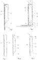
Fig. 1 is a cross-sectional view of an embodiment example of a skirting board accordi ng to the i nventi on; -
Fig. 2 is a same view asFig. 1 of an alternative embodiment example of the ski rti ng board; -
Figs. 3-5 are cross-sectional views of a skirting board in various production stages for illustrating an embodi ment example of the method according to the invention; -
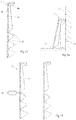
Figs. 6 and 7, 8 and 9 ,10 and 11 are views, respectively correspondi ng toFigs. 4 and 5 , of alternative embodiment examples, which do not pertain to the invention but are illustrative for some of the claimed features; -
Fig. 12 is a view corresponding toFig. 1 of an alternative skirting board, wherein the skirting board is realized as a renovation skirting board; -
Fig. 13 is a view corresponding toFig. 12 of an alternative embodiment example of a renovation skirting board; -
Fig. 14 is a same view asFig. 13 , however, illustrating a situation in which the skirting board according toFig. 13 is shortened and mounted; -
Fig. 15 is a view corresponding toFig. 13 , wherein the shortening of the skirting board according toFig. 13 is illustrated. -
Fig. 1 shows an embodiment example of a decoration system with askirting board 1 according to the invention. The decoration system comprises a floor covering 2 on which theskirting board 1 is resting. Further,Fig. 1 shows that theskirting board 1, in this case, is attached against awall 3. Hereby, theskirting board 1 forms a transition between the floor coveri ng 2 and thewall 3. In this case, the floor covering 2 comprises LVT panels. LVT is the abbreviation for Luxury Vinyl Tile, and LVT floors also are indicated as PVC floors. PVC floors often are composed of three layers, for example: a basic layer of 1-4 mm, comprising a vinyl composite, which comprises vinyl with fillers, such as plasticizers, binding agents and stabilizers, a transparent top layer, which, for example, comprises a so-called rigid vinyl film having a thickness of 0.2-1 mm and comprises vinyl with little or no plasticizers, and a decoration layer situated between the basic layer and the top layer, which can comprise a vinyl sheet of 0.1-1 mm with a printed thereon decoration pattern. A plate or panel of LVT material, on the one hand, is bendable, however, on the other hand, is rigid in a direction in the plane of the plate-shaped material. An advantage of LVT is that it is a waterproof and wear-resistant material. The LVT floor according toFig. 1 in this case also has three layers, wherein the top layer is provided with a surface structure, for example, a wood nerve structure. - The embodiment example represented in
Fig. 1 of theskirting board 1 comprises an opposedlower side 6 and afront side 7 and backside 8 situated opposite to each other. Thefront side 7 and theback side 8 extend between thelower side 6 and theupper side 5. Further, theskirting board 1 is provided with a plate-shapedmaterial 10, in this case the same type of LVT material as the floor covering 2, which is attached to thefront side 7 and theupper side 5 of thecore 4, for example, by means of gluing or laminating. InFig. 1 , a triple-layered LVT material is shown, however, a deviating number of layers are possible as well. As the plate-shapedmaterial 10 of theskirting board 1 consists of the same material as that of the floor covering 2, the top layer thereof also has the same surface structure. Moreover, it is possible that the plate-shapedmaterial 10 in fact has the same top layer and decoration layer as the floor covering, however, that the basic layer is thinner than that of the floor covering. Hereby, a thinner plate-shapedmaterial 10 can be obtained, whereas the same appearance is maintained. - The plate-shaped
material 10 covers theupper side 5 as well as thefront side 7 of thecore 4 and continues uninterruptedly from thewall 3 along theupper side 5 and thefront side 7 up to beyond thelower side 6 of thecore 4. In the installed situation of theskirting board 1, as shown inFig. 1 , the free extremity of the plate-shapedmaterial 10 rests on the floor covering 2. Hereby, a distance is present between the floor covering 2 and thecore 4. An advantage hereof is that, when water is reaching the space underneath thecore 4, comi ng from the floor covering 2, thecore 4 remai ns free from the water. T herefore, thecore 4 can be made of a relatively cheap, light and water-absorbing material, such as light-weight MDF with a lower density than 600 kg/m3. However, thecore 4 also can be made of another, possibly wood-containing, material, such as WPC, thermoplastic or extruded material. InFig. 1 is also illustrated that the space underneath the core can be applied for hiding a cable K from view. -
Fig. 1 represents a cross-section of a more or less block-shapedskirting board 1, wherein the plate-shaped material forms an angle of 90é around thecore 4, however, many alternative forms with other corner forms and corner dimensions are possible. The thickness of the plate-shapedmaterial 10 is smaller than the distance between thefront side 7 and theback side 8 of thecore 4 and also smaller than the distance between theupper side 5 and thelower side 6 of thecore 4. The thickness of the plate-shaped material is larger than 1.8 mm and more particularly the thickness is larger than 2 mm, as then the portion protrudi ng from thelower side 6 of thecore 4 offers sufficient strength. On the other hand, it is an advantage when the thickness is smaller than 2.5 mm, such that it still can be easily bent over an angle of 90é of thecore 4. -
Fig. 2 represents an alternative embodi ment example of theskirting board 1, wherein the portion of the plate-shapedmaterial 10 protruding from thelower side 6 of thecore 4 is provided with twonotches 11. Thenotches 11 are situated at the side of the plate-shapedmaterial 10 directed towards thecore 4 and extend parallel to each other in the longitudinal direction of theskirting board 1. Due to the presence of thenotches 11, the height of the skirti ng board 1 can be shortened in a simple manner, as desi red, for example, by means of a cutter knife. Thenotches 11 are made only in the basic layer of the plate-shapedmaterial 10 in order to provide for that thenotches 11 are i nvisi ble at the opposite side of the plate-shapedmaterial 10. -
Figs. 3-5 show in steps an embodiment example of the method for manufacturing askirting board 1 according to the invention. First, a large sheet of LVT of, for example, approximately 2 x 2.5 m, from which floor panels can be cut as well, is glued onto a substrate of MDF with a thickness of, for example, 8 mm, after which the obtained semi-finished product is cut to separate strips. A cross-sectional view of such strip is shown inFig. 3 . The substrate shown inFig. 3 , of which later thecore 4 will be created, is indicated with reference number 4'. The substrate 4' is block-shaped and does not yet have the form of thecore 4, such as askirting board 1 according to the invention. The length of the strip can be made in a simple manner to the standard di mension for ski rti ng boards of 2.4 m. -
Fig. 4 illustrates the strip after the substrate 4' has been milled at various locations. A mongst others, a V -groove 12 has been milled into the substrate 4', such that twoseparate core parts core parts groove 12, which contact surfaces, in a subsequent treatment step, are brought towards each other by bending the plate-shapedmaterial 10 attached to thecore parts core parts Fig. 5 , wherein the location of the glued contact surfaces is indicated by reference number 12'. -
Fig. 4 further shows that after the milling treatment arecess 13 is formed. In the fi nal skirti ng board 1, this recess serves for receiving glue for attachi ng theskirting board 1 to the wall. Further,Fig. 4 shows that the substrate 4' is milled such that thelower side 6 of thecore 4 of the finally to be formedskirting board 1 with the portion of the plate-shapedmaterial 10 protruding from thelower side 6 is created. The resultingskirting board 1 is shown inFig.5 . -
Fig. 6 and 7, 8 and 9 ,10 and 11 illustrate alternative embodi ment examples of the method for manufacturing askirting board 1. In these cases, the plate-shaped materi al is a triple-layered LVT material, as shown inFig. 1 , with successively a basic layer, decoration layer and top layer, as seen from thecore 4. InFig. 7, 9 and11 can be seen that the V-grooves 12 have different depths and shapes, which exerts an influence on the folding over of the LVT material.Fig. 7 illustrates an embodiment not pertaining to the invention wherein the V -groove 12 reaches up to the decoration layer, whereasFig. 9 illustrates an embodiment not pertaining to the invention where the V-groove 12 reaches up to the top layer. In the situation, not pertaining to the invention and accordi ng toFig. 11 , the V -groove 12 also reaches up to the decoration layer, but the tip of the V -groove 12 is flattened and thecore parts Fig. 7 . Thereby, when folding over, the tension on the top layer and decoration layer of the plate-shapedmaterial 10 is limited. -
Fig. 12 shows an alternative embodiment example of theskirting board 1. In this case, theskirting board 1 is made as a renovation skirting board. This can be applied, for example, when renovating rooms which are provided with ceramic floors and skirting boards. InFig. 12 , an existing skirting board is indicated by the letter P. Thecore 4 of theskirting board 1 has a recess in which the existing skirting board P can be received. Theback side 8 of thecore 4 can be glued against thewall 3. -
Fig. 13 shows an alternative embodiment example of arenovation skirting board 1. The core of theskirting board 1 is indicated by 4a and 4b for the core parts in order to indicate that thisskirting board 1 can be manufactured in a same manner as the herein above-described skirting boards and is illustrated, for example, inFig. 4 and 5 .Fig. 13 also shows that the core of theskirting board 1 is provided with threenotches 12. These facilitate shortening theskirting board 1, such that the desired height of theskirting board 1 can be chosen at the building site by the installing person. InFig. 15 , it is illustrated that the plate-shapedmaterial 10 at the location of a ti p of one of thenotches 12 can be cut through with acutter knife 14.Fig. 14 shows that therenovation skirting board 1 resulting therefrom can be placed over an existi ng skirting board P and can be attached thereto, for example, by means of glue. - In
Fig. 13-15 is shown that in the represented embodiment example, which does not pertain to the invention, the plate-shapedmaterial 10 of therenovation skirting board 1 does not protrude from the lower side of the core. Generally, such renovation skirting board can be defined as follows: a skirting board, comprising a core with an upper side, an opposed lower side and a front side and back side situated opposite to each other and extending between the upper side and the lower side, and a plate-shaped material, which is attached at least to the front side of the core, wherein the back side of the core is provided with one or more notches extending at a distance from the upper side in the longitudinal direction of the skirting board. Preferably, the tip of a notch reaches up to the plate-shaped material. The plate-shaped material can have the dimensions and features as described herein above. Also, the method for manufacturing such skirting board can correspond to the herein above-described method in respect to the manufacture of core parts and the folding over of the plate-shaped material. - The invention is not limited to the herein above-described embodiment examples, which can be varied in different manners within the scope of the claims.
Claims (14)
- A skirting board (1), comprising a core (4) with an upper side (5), an opposed lower side (6) and a front side (7) and back side (8) situated opposite to each other and extending between the lower side (6) and the upper side (5), and a plate-shaped material (10), which is attached to the core (4) and covers at least the front side (7), wherein the plate-shaped material (10), seen from the upper side (5) of the core (4), extends to beyond the lower side (6) of the core (4), whereby the plate-shaped material (10) is a synthetic material sheet made of a vinyl-containing material and having a thickness larger than 1.8 mm, wherein said synthetic material sheet at least comprises a basic layer, a decoration layer and a transparent top layer, wherein said plate-shaped material (10) is bent at the location of the tip of a V-groove, such that said plate-shaped material also covers said upper side (5) and wherein said V-groove (12) is provided in the core (4) in the direction of the plate-shaped material (10), however remaining remote from the top layer and the decoration layer, such that at least the side of the plate-shaped material (10) facing away from the core covers the front side (7) and the upper side (5) of the core (4) uninterruptedly.
- A skirting board (1) according to claim 1, wherein the thickness of the plate-shaped material (10) is smaller than the distance between the front side (7) and the back side (8) of the core (4) and/or is smaller than the distance between the upper side (5) and the lower side (6) of the core (4).
- A skirting board (1) according to any of the preceding claims, wherein the thickness of the plate-shaped material (10) is larger than 2 mm.
- A skirting board (1) according to any of the preceding claims, wherein the synthetic material sheet is adhered onto the core (4).
- A skirting board (1) according to any of the preceding claims, wherein the core (4) is made of a wood-containing material.
- A skirting board (1) according to any of the preceding claims, wherein the portion of the plate-shaped material (10) protruding from the lower side (6) of the core (4) is provided with at least one groove (11), which extends in the longitudinal direction of the skirting board (1) and is situated at the side of the plate-shaped material (10) directed towards the core (4).
- A skirting board (1) according to claim 6, wherein the groove is a first groove (11) and the plate-shaped material (10) is provided with at least one second groove (11), which extends parallel to the first groove (11) and is situated at the side of the plate-shaped material (10) directed towards the core (4).
- A skirting board according to any of the preceding claims, wherein said basic layer has a thickness of 1 to 4 mm and comprises a vinyl composite of vinyl and fillers.
- A skirting board according to any of the preceding claims, wherein said top layer is provided with a surface structure.
- A skirting board according to any of the preceding claims, wherein said decoration layer comprises a vinyl sheet of 0.1 to 1 mm with a printed thereon decoration pattern.
- A decoration system, comprising a floor covering (2), which is made of a luxury vinyl flooring material, and a skirting board (1) according to any of the preceding claims with a core and a plate-shaped material attached to the core (4), wherein the plate-shaped material (10) is also made of a vinyl flooring material.
- A decoration system according to claim 11, wherein said plate-shaped material and said vinyl flooring material comprise a top layer with the same surface structure.
- A method for manufacturing a skirting board (1) according to any of claims 1 to 10 with a core and a plate-shaped material attached to the core (4), wherein the core (4) to be formed comprises a first core part (4a) and a second core part (4b), which core parts (4a, 4b) are secured to the plate-shaped material (10) and each are provided with respective contact locations situated at a distance from each other, wherein the first and second core part (4a, 4b) are moved towards each other by bending the plate-shaped material (10) and are attached to each other at the contact locations in order to form the core (4) of the skirting board (1, wherein the first and second core part (4a, 4b) are formed by first securing the plate-shaped material (10) to a substrate (4') and subsequently providing a V-groove (12) in the substrate (4') in the direction of the plate-shaped material (10), wherein the plate-shaped material, seen from the substrate (4'), successively is provided with at least a basic layer, decoration layer and transparent top layer, wherein the tip of the V-groove (12) remains remote from the top layer and remains remote from the decoration layer.
- A method according to claim 13, wherein the boundary surfaces on opposite sides of the V-groove (12) form the contact locations, which are glued to each other for forming the core (4) of the skirting board (1).
Applications Claiming Priority (1)
| Application Number | Priority Date | Filing Date | Title |
|---|---|---|---|
| BE2016/5026A BE1023438B1 (en) | 2016-01-14 | 2016-01-14 | Plinth, decoration system and method for manufacturing a plinth |
Publications (2)
| Publication Number | Publication Date |
|---|---|
| EP3192939A1 EP3192939A1 (en) | 2017-07-19 |
| EP3192939B1 true EP3192939B1 (en) | 2019-08-28 |
Family
ID=55484766
Family Applications (1)
| Application Number | Title | Priority Date | Filing Date |
|---|---|---|---|
| EP17150881.5A Active EP3192939B1 (en) | 2016-01-14 | 2017-01-10 | Skirting board, decorative system and method for manufacturing a skirting board |
Country Status (4)
| Country | Link |
|---|---|
| US (1) | US20170203548A1 (en) |
| EP (1) | EP3192939B1 (en) |
| BE (1) | BE1023438B1 (en) |
| DE (1) | DE202017100562U1 (en) |
Families Citing this family (6)
| Publication number | Priority date | Publication date | Assignee | Title |
|---|---|---|---|---|
| WO2017130114A1 (en) * | 2016-01-25 | 2017-08-03 | Decruy Nv | Skirting board and an improved method for manufacturing a skirting board or finishing profiled section |
| DE202019105671U1 (en) * | 2019-10-15 | 2019-11-22 | APU Schönberg GmbH | Skirting board, ceiling molding and window or door frame insulation strip |
| US11739541B2 (en) * | 2019-11-26 | 2023-08-29 | Mcs Industries, Inc. | Cable management system |
| IT201900023565A1 (en) | 2019-12-11 | 2021-06-11 | Progress Profiles Spa | IMPROVED SKIRTING |
| CN112593673A (en) * | 2021-01-12 | 2021-04-02 | 义乌市和邦装饰工程有限公司 | Stable detecting instrument of baseboard installation |
| WO2023042332A1 (en) * | 2021-09-16 | 2023-03-23 | 日立グローバルライフソリューションズ株式会社 | Clean room facility |
Family Cites Families (11)
| Publication number | Priority date | Publication date | Assignee | Title |
|---|---|---|---|---|
| US1900987A (en) * | 1932-02-09 | 1933-03-14 | Jennie H Goff | Wall paper |
| DE1053172B (en) * | 1956-04-26 | 1959-03-19 | Herbert Ender | Elastic skirting board |
| CH355282A (en) * | 1959-04-11 | 1961-06-30 | Sandi Roland | Wooden skirting board for living space walls and process for their manufacture |
| CA2062256C (en) * | 1992-03-04 | 1995-09-12 | George Manaras | Safety baseboard molding for concealing indoor domestic wiring |
| US6122872A (en) * | 1999-04-09 | 2000-09-26 | Sauter; Mark J. | Two-part separable base molding |
| DE20000298U1 (en) * | 2000-01-08 | 2000-08-03 | W. Döllken & Co. GmbH, 45239 Essen | Core skirting board |
| US6584743B2 (en) * | 2000-04-20 | 2003-07-01 | Masonite Corporation | Decorative skirting (base) board or crown molding |
| DE10161484A1 (en) * | 2001-12-14 | 2003-06-26 | Kalman Banhidy | Wall connection profile has an elastic sealing lip and a vertical leg and coupling elements and carrying profile fixed on the rear edge of the work plate |
| BE1015825A5 (en) * | 2003-12-18 | 2005-09-06 | Flooring Ind Ltd | Plinth, FLOORING SYSTEM AND METHOD FOR MANUFACTURING A Plinth. |
| LT2339092T (en) * | 2009-12-22 | 2019-07-25 | Flooring Industries Limited, Sarl | Method for producing covering panels |
| BE1019285A3 (en) * | 2010-04-09 | 2012-05-08 | Decruy Nv | METHOD FOR MANUFACTURING A SKIRT |
-
2016
- 2016-01-14 BE BE2016/5026A patent/BE1023438B1/en not_active IP Right Cessation
-
2017
- 2017-01-10 DE DE202017100562.3U patent/DE202017100562U1/en not_active Expired - Lifetime
- 2017-01-10 EP EP17150881.5A patent/EP3192939B1/en active Active
- 2017-01-12 US US15/404,882 patent/US20170203548A1/en not_active Abandoned
Non-Patent Citations (1)
| Title |
|---|
| None * |
Also Published As
| Publication number | Publication date |
|---|---|
| BE1023438B1 (en) | 2017-03-21 |
| US20170203548A1 (en) | 2017-07-20 |
| EP3192939A1 (en) | 2017-07-19 |
| DE202017100562U1 (en) | 2017-04-10 |
Similar Documents
| Publication | Publication Date | Title |
|---|---|---|
| EP3192939B1 (en) | Skirting board, decorative system and method for manufacturing a skirting board | |
| US11649642B2 (en) | Mechanical locking system for floor panels | |
| EP3312362B1 (en) | Multi-layer elastic floor panel having a reinforced pvc core | |
| DK1938963T4 (en) | floor panel | |
| CA2979316C (en) | Impervious wall panel | |
| KR20070107125A (en) | Building panels with compressed edges | |
| EP1723291B1 (en) | Method of manufacturing a floor panel | |
| EP2700765A2 (en) | A panel and a method for manufacturing same | |
| EP2657430A2 (en) | Multi-Purpose Reducers, Systems and Methods for Production thereof | |
| CN1259185A (en) | Tile-like flat element |
Legal Events
| Date | Code | Title | Description |
|---|---|---|---|
| PUAI | Public reference made under article 153(3) epc to a published international application that has entered the european phase |
Free format text: ORIGINAL CODE: 0009012 |
|
| STAA | Information on the status of an ep patent application or granted ep patent |
Free format text: STATUS: THE APPLICATION HAS BEEN PUBLISHED |
|
| AK | Designated contracting states |
Kind code of ref document: A1 Designated state(s): AL AT BE BG CH CY CZ DE DK EE ES FI FR GB GR HR HU IE IS IT LI LT LU LV MC MK MT NL NO PL PT RO RS SE SI SK SM TR |
|
| AX | Request for extension of the european patent |
Extension state: BA ME |
|
| STAA | Information on the status of an ep patent application or granted ep patent |
Free format text: STATUS: REQUEST FOR EXAMINATION WAS MADE |
|
| 17P | Request for examination filed |
Effective date: 20180111 |
|
| RBV | Designated contracting states (corrected) |
Designated state(s): AL AT BE BG CH CY CZ DE DK EE ES FI FR GB GR HR HU IE IS IT LI LT LU LV MC MK MT NL NO PL PT RO RS SE SI SK SM TR |
|
| STAA | Information on the status of an ep patent application or granted ep patent |
Free format text: STATUS: EXAMINATION IS IN PROGRESS |
|
| 17Q | First examination report despatched |
Effective date: 20181022 |
|
| GRAP | Despatch of communication of intention to grant a patent |
Free format text: ORIGINAL CODE: EPIDOSNIGR1 |
|
| STAA | Information on the status of an ep patent application or granted ep patent |
Free format text: STATUS: GRANT OF PATENT IS INTENDED |
|
| INTG | Intention to grant announced |
Effective date: 20190426 |
|
| GRAS | Grant fee paid |
Free format text: ORIGINAL CODE: EPIDOSNIGR3 |
|
| GRAA | (expected) grant |
Free format text: ORIGINAL CODE: 0009210 |
|
| STAA | Information on the status of an ep patent application or granted ep patent |
Free format text: STATUS: THE PATENT HAS BEEN GRANTED |
|
| AK | Designated contracting states |
Kind code of ref document: B1 Designated state(s): AL AT BE BG CH CY CZ DE DK EE ES FI FR GB GR HR HU IE IS IT LI LT LU LV MC MK MT NL NO PL PT RO RS SE SI SK SM TR |
|
| REG | Reference to a national code |
Ref country code: GB Ref legal event code: FG4D |
|
| REG | Reference to a national code |
Ref country code: CH Ref legal event code: EP |
|
| REG | Reference to a national code |
Ref country code: AT Ref legal event code: REF Ref document number: 1172598 Country of ref document: AT Kind code of ref document: T Effective date: 20190915 |
|
| REG | Reference to a national code |
Ref country code: IE Ref legal event code: FG4D |
|
| REG | Reference to a national code |
Ref country code: DE Ref legal event code: R096 Ref document number: 602017006408 Country of ref document: DE |
|
| REG | Reference to a national code |
Ref country code: NL Ref legal event code: MP Effective date: 20190828 |
|
| REG | Reference to a national code |
Ref country code: LT Ref legal event code: MG4D |
|
| PG25 | Lapsed in a contracting state [announced via postgrant information from national office to epo] |
Ref country code: SE Free format text: LAPSE BECAUSE OF FAILURE TO SUBMIT A TRANSLATION OF THE DESCRIPTION OR TO PAY THE FEE WITHIN THE PRESCRIBED TIME-LIMIT Effective date: 20190828 Ref country code: HR Free format text: LAPSE BECAUSE OF FAILURE TO SUBMIT A TRANSLATION OF THE DESCRIPTION OR TO PAY THE FEE WITHIN THE PRESCRIBED TIME-LIMIT Effective date: 20190828 Ref country code: PT Free format text: LAPSE BECAUSE OF FAILURE TO SUBMIT A TRANSLATION OF THE DESCRIPTION OR TO PAY THE FEE WITHIN THE PRESCRIBED TIME-LIMIT Effective date: 20191230 Ref country code: FI Free format text: LAPSE BECAUSE OF FAILURE TO SUBMIT A TRANSLATION OF THE DESCRIPTION OR TO PAY THE FEE WITHIN THE PRESCRIBED TIME-LIMIT Effective date: 20190828 Ref country code: BG Free format text: LAPSE BECAUSE OF FAILURE TO SUBMIT A TRANSLATION OF THE DESCRIPTION OR TO PAY THE FEE WITHIN THE PRESCRIBED TIME-LIMIT Effective date: 20191128 Ref country code: NL Free format text: LAPSE BECAUSE OF FAILURE TO SUBMIT A TRANSLATION OF THE DESCRIPTION OR TO PAY THE FEE WITHIN THE PRESCRIBED TIME-LIMIT Effective date: 20190828 Ref country code: LT Free format text: LAPSE BECAUSE OF FAILURE TO SUBMIT A TRANSLATION OF THE DESCRIPTION OR TO PAY THE FEE WITHIN THE PRESCRIBED TIME-LIMIT Effective date: 20190828 Ref country code: NO Free format text: LAPSE BECAUSE OF FAILURE TO SUBMIT A TRANSLATION OF THE DESCRIPTION OR TO PAY THE FEE WITHIN THE PRESCRIBED TIME-LIMIT Effective date: 20191128 |
|
| PG25 | Lapsed in a contracting state [announced via postgrant information from national office to epo] |
Ref country code: LV Free format text: LAPSE BECAUSE OF FAILURE TO SUBMIT A TRANSLATION OF THE DESCRIPTION OR TO PAY THE FEE WITHIN THE PRESCRIBED TIME-LIMIT Effective date: 20190828 Ref country code: RS Free format text: LAPSE BECAUSE OF FAILURE TO SUBMIT A TRANSLATION OF THE DESCRIPTION OR TO PAY THE FEE WITHIN THE PRESCRIBED TIME-LIMIT Effective date: 20190828 Ref country code: IS Free format text: LAPSE BECAUSE OF FAILURE TO SUBMIT A TRANSLATION OF THE DESCRIPTION OR TO PAY THE FEE WITHIN THE PRESCRIBED TIME-LIMIT Effective date: 20191228 Ref country code: AL Free format text: LAPSE BECAUSE OF FAILURE TO SUBMIT A TRANSLATION OF THE DESCRIPTION OR TO PAY THE FEE WITHIN THE PRESCRIBED TIME-LIMIT Effective date: 20190828 Ref country code: GR Free format text: LAPSE BECAUSE OF FAILURE TO SUBMIT A TRANSLATION OF THE DESCRIPTION OR TO PAY THE FEE WITHIN THE PRESCRIBED TIME-LIMIT Effective date: 20191129 Ref country code: ES Free format text: LAPSE BECAUSE OF FAILURE TO SUBMIT A TRANSLATION OF THE DESCRIPTION OR TO PAY THE FEE WITHIN THE PRESCRIBED TIME-LIMIT Effective date: 20190828 |
|
| REG | Reference to a national code |
Ref country code: AT Ref legal event code: MK05 Ref document number: 1172598 Country of ref document: AT Kind code of ref document: T Effective date: 20190828 |
|
| PG25 | Lapsed in a contracting state [announced via postgrant information from national office to epo] |
Ref country code: TR Free format text: LAPSE BECAUSE OF FAILURE TO SUBMIT A TRANSLATION OF THE DESCRIPTION OR TO PAY THE FEE WITHIN THE PRESCRIBED TIME-LIMIT Effective date: 20190828 |
|
| PG25 | Lapsed in a contracting state [announced via postgrant information from national office to epo] |
Ref country code: PL Free format text: LAPSE BECAUSE OF FAILURE TO SUBMIT A TRANSLATION OF THE DESCRIPTION OR TO PAY THE FEE WITHIN THE PRESCRIBED TIME-LIMIT Effective date: 20190828 Ref country code: RO Free format text: LAPSE BECAUSE OF FAILURE TO SUBMIT A TRANSLATION OF THE DESCRIPTION OR TO PAY THE FEE WITHIN THE PRESCRIBED TIME-LIMIT Effective date: 20190828 Ref country code: EE Free format text: LAPSE BECAUSE OF FAILURE TO SUBMIT A TRANSLATION OF THE DESCRIPTION OR TO PAY THE FEE WITHIN THE PRESCRIBED TIME-LIMIT Effective date: 20190828 Ref country code: DK Free format text: LAPSE BECAUSE OF FAILURE TO SUBMIT A TRANSLATION OF THE DESCRIPTION OR TO PAY THE FEE WITHIN THE PRESCRIBED TIME-LIMIT Effective date: 20190828 Ref country code: AT Free format text: LAPSE BECAUSE OF FAILURE TO SUBMIT A TRANSLATION OF THE DESCRIPTION OR TO PAY THE FEE WITHIN THE PRESCRIBED TIME-LIMIT Effective date: 20190828 Ref country code: IT Free format text: LAPSE BECAUSE OF FAILURE TO SUBMIT A TRANSLATION OF THE DESCRIPTION OR TO PAY THE FEE WITHIN THE PRESCRIBED TIME-LIMIT Effective date: 20190828 |
|
| REG | Reference to a national code |
Ref country code: DE Ref legal event code: R026 Ref document number: 602017006408 Country of ref document: DE |
|
| PG25 | Lapsed in a contracting state [announced via postgrant information from national office to epo] |
Ref country code: SM Free format text: LAPSE BECAUSE OF FAILURE TO SUBMIT A TRANSLATION OF THE DESCRIPTION OR TO PAY THE FEE WITHIN THE PRESCRIBED TIME-LIMIT Effective date: 20190828 Ref country code: CZ Free format text: LAPSE BECAUSE OF FAILURE TO SUBMIT A TRANSLATION OF THE DESCRIPTION OR TO PAY THE FEE WITHIN THE PRESCRIBED TIME-LIMIT Effective date: 20190828 Ref country code: SK Free format text: LAPSE BECAUSE OF FAILURE TO SUBMIT A TRANSLATION OF THE DESCRIPTION OR TO PAY THE FEE WITHIN THE PRESCRIBED TIME-LIMIT Effective date: 20190828 Ref country code: IS Free format text: LAPSE BECAUSE OF FAILURE TO SUBMIT A TRANSLATION OF THE DESCRIPTION OR TO PAY THE FEE WITHIN THE PRESCRIBED TIME-LIMIT Effective date: 20200224 |
|
| PLBI | Opposition filed |
Free format text: ORIGINAL CODE: 0009260 |
|
| PLAX | Notice of opposition and request to file observation + time limit sent |
Free format text: ORIGINAL CODE: EPIDOSNOBS2 |
|
| 26 | Opposition filed |
Opponent name: DECRUY NV Effective date: 20200522 |
|
| PG2D | Information on lapse in contracting state deleted |
Ref country code: IS |
|
| PG25 | Lapsed in a contracting state [announced via postgrant information from national office to epo] |
Ref country code: MC Free format text: LAPSE BECAUSE OF FAILURE TO SUBMIT A TRANSLATION OF THE DESCRIPTION OR TO PAY THE FEE WITHIN THE PRESCRIBED TIME-LIMIT Effective date: 20190828 Ref country code: SI Free format text: LAPSE BECAUSE OF FAILURE TO SUBMIT A TRANSLATION OF THE DESCRIPTION OR TO PAY THE FEE WITHIN THE PRESCRIBED TIME-LIMIT Effective date: 20190828 |
|
| REG | Reference to a national code |
Ref country code: CH Ref legal event code: PL |
|
| PLBB | Reply of patent proprietor to notice(s) of opposition received |
Free format text: ORIGINAL CODE: EPIDOSNOBS3 |
|
| PG25 | Lapsed in a contracting state [announced via postgrant information from national office to epo] |
Ref country code: LU Free format text: LAPSE BECAUSE OF NON-PAYMENT OF DUE FEES Effective date: 20200110 |
|
| PG25 | Lapsed in a contracting state [announced via postgrant information from national office to epo] |
Ref country code: CH Free format text: LAPSE BECAUSE OF NON-PAYMENT OF DUE FEES Effective date: 20200131 Ref country code: LI Free format text: LAPSE BECAUSE OF NON-PAYMENT OF DUE FEES Effective date: 20200131 |
|
| PG25 | Lapsed in a contracting state [announced via postgrant information from national office to epo] |
Ref country code: IE Free format text: LAPSE BECAUSE OF NON-PAYMENT OF DUE FEES Effective date: 20200110 |
|
| REG | Reference to a national code |
Ref country code: DE Ref legal event code: R081 Ref document number: 602017006408 Country of ref document: DE Owner name: FLOORING INDUSTRIES LIMITED, SARL, LU Free format text: FORMER OWNER: IVC, BVBA, AVELGEM, BE Ref country code: BE Ref legal event code: PD Owner name: FLOORING INDUSTRIES LIMITED, SARL; LU Free format text: DETAILS ASSIGNMENT: CHANGE OF OWNER(S), CHANGE OF LEGAL ENTITY; FORMER OWNER NAME: IVC BV Effective date: 20210723 |
|
| GBPC | Gb: european patent ceased through non-payment of renewal fee |
Effective date: 20210110 |
|
| RAP2 | Party data changed (patent owner data changed or rights of a patent transferred) |
Owner name: FLOORING INDUSTRIES LIMITED, SARL |
|
| PG25 | Lapsed in a contracting state [announced via postgrant information from national office to epo] |
Ref country code: GB Free format text: LAPSE BECAUSE OF NON-PAYMENT OF DUE FEES Effective date: 20210110 |
|
| PLBD | Termination of opposition procedure: decision despatched |
Free format text: ORIGINAL CODE: EPIDOSNOPC1 |
|
| PLBP | Opposition withdrawn |
Free format text: ORIGINAL CODE: 0009264 |
|
| REG | Reference to a national code |
Ref country code: DE Ref legal event code: R100 Ref document number: 602017006408 Country of ref document: DE |
|
| PLBM | Termination of opposition procedure: date of legal effect published |
Free format text: ORIGINAL CODE: 0009276 |
|
| PGFP | Annual fee paid to national office [announced via postgrant information from national office to epo] |
Ref country code: DE Payment date: 20220127 Year of fee payment: 6 |
|
| 27C | Opposition proceedings terminated |
Effective date: 20220102 |
|
| PG25 | Lapsed in a contracting state [announced via postgrant information from national office to epo] |
Ref country code: MT Free format text: LAPSE BECAUSE OF FAILURE TO SUBMIT A TRANSLATION OF THE DESCRIPTION OR TO PAY THE FEE WITHIN THE PRESCRIBED TIME-LIMIT Effective date: 20190828 Ref country code: CY Free format text: LAPSE BECAUSE OF FAILURE TO SUBMIT A TRANSLATION OF THE DESCRIPTION OR TO PAY THE FEE WITHIN THE PRESCRIBED TIME-LIMIT Effective date: 20190828 |
|
| PGFP | Annual fee paid to national office [announced via postgrant information from national office to epo] |
Ref country code: FR Payment date: 20220125 Year of fee payment: 6 Ref country code: BE Payment date: 20220127 Year of fee payment: 6 |
|
| PG25 | Lapsed in a contracting state [announced via postgrant information from national office to epo] |
Ref country code: MK Free format text: LAPSE BECAUSE OF FAILURE TO SUBMIT A TRANSLATION OF THE DESCRIPTION OR TO PAY THE FEE WITHIN THE PRESCRIBED TIME-LIMIT Effective date: 20190828 |
|
| REG | Reference to a national code |
Ref country code: DE Ref legal event code: R119 Ref document number: 602017006408 Country of ref document: DE |
|
| REG | Reference to a national code |
Ref country code: BE Ref legal event code: MM Effective date: 20230131 |
|
| PG25 | Lapsed in a contracting state [announced via postgrant information from national office to epo] |
Ref country code: DE Free format text: LAPSE BECAUSE OF NON-PAYMENT OF DUE FEES Effective date: 20230801 |
|
| PG25 | Lapsed in a contracting state [announced via postgrant information from national office to epo] |
Ref country code: FR Free format text: LAPSE BECAUSE OF NON-PAYMENT OF DUE FEES Effective date: 20230131 Ref country code: BE Free format text: LAPSE BECAUSE OF NON-PAYMENT OF DUE FEES Effective date: 20230131 |
|
| PG25 | Lapsed in a contracting state [announced via postgrant information from national office to epo] |
Ref country code: IS Free format text: LAPSE BECAUSE OF NON-PAYMENT OF DUE FEES Effective date: 20200224 |