EP3192405A1 - Hanger with magnets - Google Patents
Hanger with magnets Download PDFInfo
- Publication number
- EP3192405A1 EP3192405A1 EP16180386.1A EP16180386A EP3192405A1 EP 3192405 A1 EP3192405 A1 EP 3192405A1 EP 16180386 A EP16180386 A EP 16180386A EP 3192405 A1 EP3192405 A1 EP 3192405A1
- Authority
- EP
- European Patent Office
- Prior art keywords
- hanger
- wings
- operative configuration
- magnets
- elongated elements
- Prior art date
- Legal status (The legal status is an assumption and is not a legal conclusion. Google has not performed a legal analysis and makes no representation as to the accuracy of the status listed.)
- Withdrawn
Links
- 230000000903 blocking effect Effects 0.000 claims abstract description 7
- 230000008878 coupling Effects 0.000 description 6
- 238000010168 coupling process Methods 0.000 description 6
- 238000005859 coupling reaction Methods 0.000 description 6
- 230000006978 adaptation Effects 0.000 description 1
- 239000004744 fabric Substances 0.000 description 1
- 239000000463 material Substances 0.000 description 1
Images



Classifications
-
- A—HUMAN NECESSITIES
- A47—FURNITURE; DOMESTIC ARTICLES OR APPLIANCES; COFFEE MILLS; SPICE MILLS; SUCTION CLEANERS IN GENERAL
- A47G—HOUSEHOLD OR TABLE EQUIPMENT
- A47G25/00—Household implements used in connection with wearing apparel; Dress, hat or umbrella holders
- A47G25/02—Dress holders; Dress suspending devices; Clothes-hanger assemblies; Clothing lifters
- A47G25/06—Clothes hooks; Clothes racks; Garment-supporting stands with swingable or extending arms
- A47G25/0685—Collapsible clothes racks, e.g. swingable, foldable, extendible
-
- A—HUMAN NECESSITIES
- A47—FURNITURE; DOMESTIC ARTICLES OR APPLIANCES; COFFEE MILLS; SPICE MILLS; SUCTION CLEANERS IN GENERAL
- A47G—HOUSEHOLD OR TABLE EQUIPMENT
- A47G25/00—Household implements used in connection with wearing apparel; Dress, hat or umbrella holders
- A47G25/14—Clothing hangers, e.g. suit hangers
- A47G25/40—Collapsible hangers
- A47G25/4015—Collapsible hangers comprising one-piece support arms at least one only pivotally-connected to a central hook member
- A47G25/4023—Collapsible hangers comprising one-piece support arms at least one only pivotally-connected to a central hook member collapsing downwardly away from the hook member
-
- A—HUMAN NECESSITIES
- A47—FURNITURE; DOMESTIC ARTICLES OR APPLIANCES; COFFEE MILLS; SPICE MILLS; SUCTION CLEANERS IN GENERAL
- A47G—HOUSEHOLD OR TABLE EQUIPMENT
- A47G2200/00—Details not otherwise provided for in A47G
- A47G2200/10—Magnetism
- A47G2200/106—Permanent
Definitions
- the present invention refers to the field of the devices suitable for holding garments.
- the present invention refers to a hanger and foldable hanger.
- Traditional hangers are devices provided with a couple of supporting wings of a garment and of a central element provided with of a hook suitable for being hanged to a bracket or supporting bar.
- known hangers are further provided with wings directed downwards.
- Some hanger of a known type have furthermore a central beam that joints the ends of the two wings. Said central beam, is typically used for holding trousers in such a way that they can be put below an outwear that instead is placed on the wings of the hanger.
- hangers have the drawback of not being foldable, and therefore of occupying a relevant space also in case they are not used.
- the scope of the present invention is therefore to describe a foldable-type hanger of that solves the aforementioned drawbacks.
- the present invention is targeted to describe a foldable-type hanger that allows for occupying a small space in case folded and that at the same time offers a valid support to the heavy garments when in use.
- the hanger object of the present invention sees the presence of magnets for being arranged in an operative position wherein the wings are open.
- a foldable hanger characterized in that it comprises a couple of elongated elements or wings rotating one respective to the other along a central axis of rotation in correspondence of a their central portion positioned on a first end thereof, and wherein said hanger comprises a first operative configuration wherein said elongated elements or wings are rotated so that to rest the one in proximity of the other at a first minimum distance, and a second operative configuration wherein said elongated elements or wings are positioned to a distance which is angularly greater respective to said first minimum distance and are suitable for holding a suit; said hanger comprising movable blocking means in said second operative configuration.
- said movable blocking means are magnets positioned in respective recesses on each of the said central portions.
- said magnets are axially aligned on a respective axis which is parallel to said central axis of rotation.
- said magnets rest flow with the inner surface of the central portions.
- each of the two central portions comprises means of engagement for the reciprocal engagement of the two central portions of the first and of the second wing, wherein a first engagement means is a dovetail recess; a second engagement means is a dovetail-arched prominence.
- said second operative configuration ceases in case the magnets are reciprocally misaligned by means of a pressure on the ends of said elongated elements or wings with a force having a value comprised between 5 and 10 kg.
- the ends of said elongated elements or wings have an increased section.
- said movable blocking means are blockable elastic elements susceptible of automatically bring, when unblocked, said hanger from said first to said second operative configuration.
- hanger shall be meant a equivalently a coat hanger, a hanger or a rack , i.e. an accessory device used for sustaining garments for the purpose of stacking them in a wardrobe or in specific stands.
- the foldable hanger 100 comprises a couple of elements or wings 101, 102, each of which is formed by a bar substantially linearly extended which ends in correspondence of a own end 103 with a circular portion 104.
- the circular portion 104 of each of the couples of elements or wings 101, 102 is configured for coupling with the corresponding circular portion 104 of the other wing.
- the elements or wings 101, 102 are substantially symmetrical.
- the circular portion 104 has a plurality of recesses 105 106 within which are positioned magnets 107.
- the magnets 107 are conceived for allowing to keeping open the hanger in case in operative position.
- the recesses 105, 106 are such that the magnets 107 are flush with the inner wall of the central portions 104 that faces on the reciprocal opposite.
- the hanger 100 object of the present invention has a first operative configuration wherein the wings 101, 102 are folded and a second operative configuration wherein the wings 101, 102 are open, and wherein the hanger is ready to house a garment.
- the recesses 105, 106 are positioned in such a way that the magnets which are present on the circular portions 104 of each of the wings 101, 102 are faced one to the other in case the rotation reciprocal of the wings 101, 102 brings the hanger 100 object of the present invention in said second operative configuration.
- the wings 101, 102 can be folded up to the point of being axially substantially aligned, occupying therefore the least possible space having furthermore the magnets 107 which are not axially aligned, the reciprocal rotation of the wings 101, 102 around the axis X allows bringing the magnets 107 of the two circular portions 104 in substantial axial coupling in a second operative configuration shown in figure 2 .
- the magnets 107 are oriented in such a way to have reciprocally attracting poles when in axial coupling. This means that if a magnet 107 of the circular portion 104 of the first wing 101 has a pole N directed outwards, and that is towards the second circular portion 104, the corresponding magnet 107 of the second circular portion will instead present a magnet with the S pole directed outwards, and towards the first circular portion 104.
- the magnetic attraction force that the magnets 107 can generate is calculated basing on the weight that the wings 101, 102 of the hanger can withstand, as well as on the material with which those are produced and - finally - in function of their length. In fact, the more the wings 101, 102 are long, the greater is the lever with which they act on the circular portion 104 wherein there are the magnets 107.
- the magnets are rendered such that they have an attraction force for which their reciprocal disengagement in case are positioned into the second operative configuration is given by a force exerted on the ends of the wings 101, 102 equal to 10kg.
- the minimum force necessary for disengaging the magnets from the reciprocal alignment is 5kg.
- the hanger object of the present invention has in correspondence of the circular portions 104 of the means of engagement 111, 112 for the reciprocal engagement of the two circular portions 104 of the first and of the second wing.
- a first engagement means 111 is a dovetail recess; a second engagement means 112 is a dovetail arched prominence.
- each circular portion has a respective central through hole positioned and oriented on the axis X, that allows the passage of the coupling screw 120.
- each one of the two wings 101, 102 ends with shoulders of increased size that advantageously allow of offering a greater contact are with the shoulders of the garment.
- the magnets 107, for each circular portion 104 are at least two in number. Therefore said number can be varied in accordance to their magnetic force.
- a of the two circular portions 104 is provided with a hook 130 or of an equivalent means for allowing to hang the hanger object of the present invention to the respective support.
- the hanger object of the present invention has finally a visible surface 104v of the circular portion that is suitable for containing therein a logo or equivalent graphic means representing a trademark or similar.
- the use of the hanger 100 object of the present invention advantageously allows for example for hanging round neck pullovers or sweaters or anyway garments with a neck opening smaller than the maximum extension that the hanger when deployed can have, without forcing on the neck opening itself.
Landscapes
- Holders For Apparel And Elements Relating To Apparel (AREA)
Abstract
Foldable hanger (100), characterized in that it comprises a couple of elongated elements or wings (101, 102) rotating one respective to the other along a central axis of rotation (X) in correspondence of an own central portion (104) arranged on a first end thereof, and wherein said hanger (100) comprises a first operative configuration wherein said elongated elements or wings (101, 102) are rotated so that to rest one in proximity of the other at a first minimum distance, and a second operative configuration wherein said elongated elements or wings (101, 102) are positioned at a distance angularly greater respective to said first minimum distance and are suitable for holding a suit; said hanger (100) comprising movable blocking means (107) in said second operative configuration.
Description
- The present invention refers to the field of the devices suitable for holding garments. In detail the present invention refers to a hanger and foldable hanger.
- Traditional hangers are devices provided with a couple of supporting wings of a garment and of a central element provided with of a hook suitable for being hanged to a bracket or supporting bar. Typically, known hangers are further provided with wings directed downwards.
- Some hanger of a known type have furthermore a central beam that joints the ends of the two wings. Said central beam, is typically used for holding trousers in such a way that they can be put below an outwear that instead is placed on the wings of the hanger.
- The applicant has noticed that known hangers have the drawback of not being foldable, and therefore of occupying a relevant space also in case they are not used.
- The applicant has furthermore noticed that often many outwears have small neck apertures, and that the traditional users attempt to stretch or broaden said aperture in such a way to allow the passage of the traditional rigid hanger. This many times bring to tear the cloth in the zone of the neck or, alternatively, in proceeding with a greater broadening of the zone of the neck that consequently cannot return to the traditional size.
- The scope of the present invention is therefore to describe a foldable-type hanger of that solves the aforementioned drawbacks.
- The present invention is targeted to describe a foldable-type hanger that allows for occupying a small space in case folded and that at the same time offers a valid support to the heavy garments when in use. The hanger object of the present invention sees the presence of magnets for being arranged in an operative position wherein the wings are open.
- According to the present invention is therefore realized a foldable hanger, characterized in that it comprises a couple of elongated elements or wings rotating one respective to the other along a central axis of rotation in correspondence of a their central portion positioned on a first end thereof, and wherein said hanger comprises a first operative configuration wherein said elongated elements or wings are rotated so that to rest the one in proximity of the other at a first minimum distance, and a second operative configuration wherein said elongated elements or wings are positioned to a distance which is angularly greater respective to said first minimum distance and are suitable for holding a suit; said hanger comprising movable blocking means in said second operative configuration.
- According to a first aspect of the present invention, said movable blocking means are magnets positioned in respective recesses on each of the said central portions. According to a further aspect of the present invention, in said second operative configuration said magnets are axially aligned on a respective axis which is parallel to said central axis of rotation.
- According to a further aspect of the present invention, said magnets rest flow with the inner surface of the central portions.
- In detail, each of the two central portions comprises means of engagement for the reciprocal engagement of the two central portions of the first and of the second wing, wherein a first engagement means is a dovetail recess; a second engagement means is a dovetail-arched prominence.
- According to a further aspect of the present invention, if the means of engagement are not present, in correspondence of said central axis of rotation there is a through hole for letting a screw of reciprocal rotating fastening between said first or second elongated element pass.
- For the purpose of having a correct keeping for heavy suits, said second operative configuration ceases in case the magnets are reciprocally misaligned by means of a pressure on the ends of said elongated elements or wings with a force having a value comprised between 5 and 10 kg.
- According to a further aspect of the present invention, furthermore, the ends of said elongated elements or wings have an increased section.
- According to a further aspect of the present invention, it is possible to cause that said movable blocking means are blockable elastic elements susceptible of automatically bring, when unblocked, said hanger from said first to said second operative configuration.
- The invention will be herein described referring to the annexed figures in a preferred and non-limiting embodiment thereof. In the annexed figures,
-
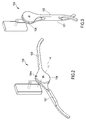
figure 1 shows a plane view of a foldable hanger object of the present invention; -
figure 2 shows a perspective view of the foldable hanger offigure 1 , in a first operative configuration; -
figure 3 shows a perspective view of the foldable hanger offigure 1 , in a second operative configuration; -
figure 4 shows a exploded view of the foldable hanger object of the present invention; -
figure 5 shows a plane view of a part of the foldable hanger object of the present invention; e -
figure 6 shows a section view of an alternative embodiment of the foldable hanger object of the present invention. - For the purposes of the present invention, with the wording hanger shall be meant a equivalently a coat hanger, a hanger or a rack , i.e. an accessory device used for sustaining garments for the purpose of stacking them in a wardrobe or in specific stands.
- With reference to
figure 1 , with thereference number 100 is shown in its complex a foldable hanger. - The
foldable hanger 100, comprises a couple of elements orwings own end 103 with acircular portion 104. Thecircular portion 104 of each of the couples of elements orwings circular portion 104 of the other wing. The elements orwings - In correspondence of the central position of the
circular portion 104, there is an ideal axis X which represents the axis of rotation is reciprocal of the twowings - As it is shown in
figure 4 , thecircular portion 104 has a plurality ofrecesses 105 106 within which are positionedmagnets 107. Themagnets 107 are conceived for allowing to keeping open the hanger in case in operative position. In detail, therecesses magnets 107 are flush with the inner wall of thecentral portions 104 that faces on the reciprocal opposite. - In fact the
hanger 100 object of the present invention has a first operative configuration wherein thewings wings - As it is shown in
figure 4 and infigure 5 , therecesses circular portions 104 of each of thewings wings hanger 100 object of the present invention in said second operative configuration. - In fact, while in the first operative configuration, shown in
figure 3 , thewings magnets 107 which are not axially aligned, the reciprocal rotation of thewings magnets 107 of the twocircular portions 104 in substantial axial coupling in a second operative configuration shown infigure 2 . - The
magnets 107 are oriented in such a way to have reciprocally attracting poles when in axial coupling. This means that if amagnet 107 of thecircular portion 104 of thefirst wing 101 has a pole N directed outwards, and that is towards the secondcircular portion 104, thecorresponding magnet 107 of the second circular portion will instead present a magnet with the S pole directed outwards, and towards the firstcircular portion 104. - Therefore, in case reciprocal the rotation of the
wings magnets 107 faced one to the other so that movably block thewings - The magnetic attraction force that the
magnets 107 can generate is calculated basing on the weight that thewings wings circular portion 104 wherein there are themagnets 107. - Preferably even though in a non-limiting extent the magnets are rendered such that they have an attraction force for which their reciprocal disengagement in case are positioned into the second operative configuration is given by a force exerted on the ends of the
wings - In a preferred and non-limiting embodiment, the hanger object of the present invention has in correspondence of the
circular portions 104 of the means ofengagement circular portions 104 of the first and of the second wing. - A first engagement means 111 is a dovetail recess; a second engagement means 112 is a dovetail arched prominence.
- Alternatively, as it is shown in
figure 4 , into the central portion of thecircular portions 104 there is acoupling screw 120. In said case, each circular portion has a respective central through hole positioned and oriented on the axis X, that allows the passage of thecoupling screw 120. - In a preferred but non-limiting embodiment, each one of the two
wings - As it is shown in
figure 4 , themagnets 107, for eachcircular portion 104 are at least two in number. Anyway said number can be varied in accordance to their magnetic force. - Furthermore, a of the two
circular portions 104 is provided with ahook 130 or of an equivalent means for allowing to hang the hanger object of the present invention to the respective support. - In a preferred and non-limiting embodiment of the present invention, the hanger object of the present invention has finally a
visible surface 104v of the circular portion that is suitable for containing therein a logo or equivalent graphic means representing a trademark or similar. - Furthermore, even if in the course of the present description reference has been made to an
hanger 100 provided with of centralcircular portions 104, said configuration of shape shall not be intended as limitative. Other shapes in fact can be equivalently used without that this causes a variation in the technical operation of the invention. - The advantages of the foldable hanger object of the present invention are clear in the light of the description that precedes. It advantageously allows for occupying less space when folded and at the same time allows for providing a valid support for the garments when positioned in said operative configuration.
- The substantial symmetry of the two
wings central fastening screw 120, renders the realization of thehanger 100 particularly advantageous in terms of economy. - In particular, the use of the
hanger 100 object of the present invention advantageously allows for example for hanging round neck pullovers or sweaters or anyway garments with a neck opening smaller than the maximum extension that the hanger when deployed can have, without forcing on the neck opening itself. - In other words, through the hanger object of the present invention is no more necessary to turn the sweater upside down for causing the introduction within the hanger.
- It is finally clear that to the
hanger 100 object of the present invention can be applied addition, adaptations or variants, obvious for a skilled person, without for this departing from the scope of protection provided by the annexed claims. - For example, it is possible to add a spring with block that allows of automatically bringing the hanger object of the present invention from the first to the second operative configuration.
Claims (9)
- Foldable hanger (100), characterized in that it comprises a couple of elongated elements or wings (101, 102) rotating one respective to the other along a central axis of rotation (X) in correspondence of a their central portion (104) arranged on a first end thereof, and wherein said hanger (100) comprises a first operative configuration wherein said elongated elements or wings (101, 102) are rotating so that to rest one in proximity of the other at a first minimum distance, and a second operative configuration wherein said elongated elements or wings (101, 102) are positioned to a distance which is angularly greater respective to said first minimum distance and are suitable for holding a suit; said hanger (100) comprising movable blocking means (107) in said second operative configuration.
- Hanger (100) according to claim 1, characterized in that said movable blocking means (107) are magnets positioned in respective recesses (105, 106) on each of the said central portions (104).
- Hanger (100) according to claim 2, wherein in said second operative configuration said magnets (107) are axially aligned on a respective axis (Y) which is parallel to said central axis of rotation.
- Hanger (100) according to claim 2 or claim 3, wherein said magnets (107) are flush with the inner surface of the central portions (104).
- Hanger (100) according to any of the preceding claims, wherein each of the two central portions (104) comprises means of engagement (111, 112) for the reciprocal engagement of the two central portions (104) of the first and of the second wing, wherein a first engagement means (111) is a dovetail recess; a second engagement means (112) is a dovetail-arched prominence.
- Hanger (100) according to any of the preceding claims 1-4, wherein in correspondence of said central axis of rotation (X) there is a through hole for letting a screw (120) of reciprocal rotating fastening between said first or second elongated element or wing (101, 102) pass.
- Hanger (100) according to any of the preceding claims, characterized in that said second operative configuration ceases in case the magnets (107) are reciprocally misaligned by means of a pressure on the ends of said elongated elements or wings (101, 102) with a force having value comprised between 5 and 10 kg.
- Hanger (100) according to any of the preceding claims, characterized in that the ends of said elongated elements or wings (101, 102) have an increased section.
- Hanger (100) according to claim 1, characterized in that said movable blocking means (107) are blockable elastic elements susceptible of automatically bringing, when unlocked, said hanger (100) from said first to said second operative configuration.
Applications Claiming Priority (1)
| Application Number | Priority Date | Filing Date | Title |
|---|---|---|---|
| CH63202016 | 2016-01-18 |
Publications (1)
| Publication Number | Publication Date |
|---|---|
| EP3192405A1 true EP3192405A1 (en) | 2017-07-19 |
Family
ID=56617996
Family Applications (1)
| Application Number | Title | Priority Date | Filing Date |
|---|---|---|---|
| EP16180386.1A Withdrawn EP3192405A1 (en) | 2016-01-18 | 2016-07-20 | Hanger with magnets |
Country Status (1)
| Country | Link |
|---|---|
| EP (1) | EP3192405A1 (en) |
Cited By (1)
| Publication number | Priority date | Publication date | Assignee | Title |
|---|---|---|---|---|
| CN111493625A (en) * | 2020-04-27 | 2020-08-07 | 罗龙英 | Clothes hanger convenient for pulling off clothes |
Citations (3)
| Publication number | Priority date | Publication date | Assignee | Title |
|---|---|---|---|---|
| US20040211797A1 (en) * | 2003-04-22 | 2004-10-28 | Gary Landis | Folding garment hanger |
| CH708907A2 (en) * | 2013-11-28 | 2015-05-29 | Adrian Märklin | Foldable hanger. |
| WO2017048806A1 (en) * | 2015-09-14 | 2017-03-23 | Brad Alan Snow | Collapsible hanger to reduce creasing |
-
2016
- 2016-07-20 EP EP16180386.1A patent/EP3192405A1/en not_active Withdrawn
Patent Citations (3)
| Publication number | Priority date | Publication date | Assignee | Title |
|---|---|---|---|---|
| US20040211797A1 (en) * | 2003-04-22 | 2004-10-28 | Gary Landis | Folding garment hanger |
| CH708907A2 (en) * | 2013-11-28 | 2015-05-29 | Adrian Märklin | Foldable hanger. |
| WO2017048806A1 (en) * | 2015-09-14 | 2017-03-23 | Brad Alan Snow | Collapsible hanger to reduce creasing |
Cited By (1)
| Publication number | Priority date | Publication date | Assignee | Title |
|---|---|---|---|---|
| CN111493625A (en) * | 2020-04-27 | 2020-08-07 | 罗龙英 | Clothes hanger convenient for pulling off clothes |
Similar Documents
| Publication | Publication Date | Title |
|---|---|---|
| US9055834B2 (en) | Adjustable garment hanger | |
| US20150150399A1 (en) | Foldable clothes hanger | |
| US6230945B1 (en) | Through-the-neck garment hanger | |
| EP3192405A1 (en) | Hanger with magnets | |
| US1750905A (en) | Stocking hanger | |
| US20150342383A1 (en) | Hanger | |
| EP3107427B1 (en) | Hanger for hanging garments | |
| CH712043A2 (en) | Foldable coat rack | |
| US2419638A (en) | Hanger | |
| US2426556A (en) | Garment hanger | |
| US2276429A (en) | Combination garment hanger | |
| EP3366177B1 (en) | Device for supporting kitchen objects | |
| TWM501799U (en) | Magnetic hanger | |
| US2280435A (en) | Garment hanger | |
| US20160045050A1 (en) | Clothes hanger | |
| US2109584A (en) | Garment hanger | |
| GB2597704A (en) | Extendable telescopic outfit hanger | |
| US1617116A (en) | Combination coat and trouser hanger | |
| CN203041754U (en) | Multifunctional anti-dropping hanger with two hooks | |
| TW201625163A (en) | Magnetic hanger | |
| KR102169402B1 (en) | A Holder for a Plural of Clothe Hangers | |
| CN204617829U (en) | A kind of retracted hanger | |
| US770891A (en) | Garment-hanger. | |
| KR20170085807A (en) | Folding type hanger | |
| GB202108016D0 (en) | Clothes hanger with extendable arms and trouser bar |
Legal Events
| Date | Code | Title | Description |
|---|---|---|---|
| PUAI | Public reference made under article 153(3) epc to a published international application that has entered the european phase |
Free format text: ORIGINAL CODE: 0009012 |
|
| STAA | Information on the status of an ep patent application or granted ep patent |
Free format text: STATUS: THE APPLICATION HAS BEEN PUBLISHED |
|
| AK | Designated contracting states |
Kind code of ref document: A1 Designated state(s): AL AT BE BG CH CY CZ DE DK EE ES FI FR GB GR HR HU IE IS IT LI LT LU LV MC MK MT NL NO PL PT RO RS SE SI SK SM TR |
|
| AX | Request for extension of the european patent |
Extension state: BA ME |
|
| STAA | Information on the status of an ep patent application or granted ep patent |
Free format text: STATUS: THE APPLICATION IS DEEMED TO BE WITHDRAWN |
|
| 18D | Application deemed to be withdrawn |
Effective date: 20180120 |