EP3191736B1 - Hybrid orbitless gearbox - Google Patents
Hybrid orbitless gearbox Download PDFInfo
- Publication number
- EP3191736B1 EP3191736B1 EP15839548.3A EP15839548A EP3191736B1 EP 3191736 B1 EP3191736 B1 EP 3191736B1 EP 15839548 A EP15839548 A EP 15839548A EP 3191736 B1 EP3191736 B1 EP 3191736B1
- Authority
- EP
- European Patent Office
- Prior art keywords
- offset
- axis
- coupling
- carrier
- members
- Prior art date
- Legal status (The legal status is an assumption and is not a legal conclusion. Google has not performed a legal analysis and makes no representation as to the accuracy of the status listed.)
- Active
Links
- 238000010168 coupling process Methods 0.000 claims description 133
- 238000005859 coupling reaction Methods 0.000 claims description 133
- 230000008878 coupling Effects 0.000 claims description 132
- 239000000969 carrier Substances 0.000 claims description 20
- 238000000034 method Methods 0.000 claims 10
- WYTGDNHDOZPMIW-RCBQFDQVSA-N alstonine Natural products C1=CC2=C3C=CC=CC3=NC2=C2N1C[C@H]1[C@H](C)OC=C(C(=O)OC)[C@H]1C2 WYTGDNHDOZPMIW-RCBQFDQVSA-N 0.000 description 5
- 239000003638 chemical reducing agent Substances 0.000 description 2
- 239000000463 material Substances 0.000 description 2
- 230000003466 anti-cipated effect Effects 0.000 description 1
- 230000005540 biological transmission Effects 0.000 description 1
- 238000000576 coating method Methods 0.000 description 1
- 150000001875 compounds Chemical class 0.000 description 1
- 229910052745 lead Inorganic materials 0.000 description 1
- 239000000314 lubricant Substances 0.000 description 1
- 239000002184 metal Substances 0.000 description 1
- 229910052751 metal Inorganic materials 0.000 description 1
- 238000004381 surface treatment Methods 0.000 description 1
Images



Classifications
-
- F—MECHANICAL ENGINEERING; LIGHTING; HEATING; WEAPONS; BLASTING
- F16—ENGINEERING ELEMENTS AND UNITS; GENERAL MEASURES FOR PRODUCING AND MAINTAINING EFFECTIVE FUNCTIONING OF MACHINES OR INSTALLATIONS; THERMAL INSULATION IN GENERAL
- F16H—GEARING
- F16H1/00—Toothed gearings for conveying rotary motion
- F16H1/02—Toothed gearings for conveying rotary motion without gears having orbital motion
- F16H1/20—Toothed gearings for conveying rotary motion without gears having orbital motion involving more than two intermeshing members
-
- F—MECHANICAL ENGINEERING; LIGHTING; HEATING; WEAPONS; BLASTING
- F16—ENGINEERING ELEMENTS AND UNITS; GENERAL MEASURES FOR PRODUCING AND MAINTAINING EFFECTIVE FUNCTIONING OF MACHINES OR INSTALLATIONS; THERMAL INSULATION IN GENERAL
- F16H—GEARING
- F16H1/00—Toothed gearings for conveying rotary motion
- F16H1/02—Toothed gearings for conveying rotary motion without gears having orbital motion
-
- F—MECHANICAL ENGINEERING; LIGHTING; HEATING; WEAPONS; BLASTING
- F16—ENGINEERING ELEMENTS AND UNITS; GENERAL MEASURES FOR PRODUCING AND MAINTAINING EFFECTIVE FUNCTIONING OF MACHINES OR INSTALLATIONS; THERMAL INSULATION IN GENERAL
- F16H—GEARING
- F16H57/00—General details of gearing
- F16H57/02—Gearboxes; Mounting gearing therein
-
- F—MECHANICAL ENGINEERING; LIGHTING; HEATING; WEAPONS; BLASTING
- F16—ENGINEERING ELEMENTS AND UNITS; GENERAL MEASURES FOR PRODUCING AND MAINTAINING EFFECTIVE FUNCTIONING OF MACHINES OR INSTALLATIONS; THERMAL INSULATION IN GENERAL
- F16H—GEARING
- F16H57/00—General details of gearing
- F16H57/02—Gearboxes; Mounting gearing therein
- F16H57/023—Mounting or installation of gears or shafts in the gearboxes, e.g. methods or means for assembly
-
- F—MECHANICAL ENGINEERING; LIGHTING; HEATING; WEAPONS; BLASTING
- F16—ENGINEERING ELEMENTS AND UNITS; GENERAL MEASURES FOR PRODUCING AND MAINTAINING EFFECTIVE FUNCTIONING OF MACHINES OR INSTALLATIONS; THERMAL INSULATION IN GENERAL
- F16H—GEARING
- F16H57/00—General details of gearing
- F16H57/02—Gearboxes; Mounting gearing therein
- F16H2057/02039—Gearboxes for particular applications
Definitions
- the disclosure herein relates to a gearbox comprising a plurality of gears or other engaging members. More particularly, it relates to an apparatus providing a drive member that rotates at a different rate as a driven member.
- An Orbitless gearbox ( US 9,970,509 B2; published on 16 March 2017 , after the priority date and filing date of the present application) comprises a central gear and a number of offset crankshaft pinions, carried by a pair of offset carriers. It has lower pitch velocity, bearing speed, and windage than a Planetary gearbox ( US 627,977; published on 4 July 1899 ) but produces a lower speed ratio. It is, therefore, more energy efficient, but requires a greater volume for a given speed ratio.
- a Coupled Orbitless gearbox comprises coupling members which engage the central and offset members whereby they rotate in a common direction. This amplifies and inverts the speed ratio so that the roles of the input and output members are interchanged. Since the carriers are the output of an Orbitless reduction gearbox and the input of a Coupled Orbitless reduction gearbox, integrating an Orbitless first stage with a Coupled Orbitless second stage, allows a common set of carriers and offset members to be shared by both stages.
- a Hybrid Orbitless gearbox combines the superior efficiency and highspeed characteristics of an Orbitless gearbox with the high reduction ratio of a Coupled Orbitless gearbox.
- GB 2,221,278 A describes a planetary gear system comprising an input shaft, an output shaft and at least one meshing gear-pair connecting the input shaft to the output shaft.
- One of the gears of the gear-pair is eccentrically mounted relative to the input shaft.
- the system includes at least one crank member having a first bearing end engaged with the eccentrically mounted gear and a second bearing end, offset with respect to the first, which is engaged with either a further gear or a fixed member.
- the system is provided with balancing means.
- US 4,896,567 describes a planetary transmission mechanism and device of involute gears with compound small tooth-difference having two internal gear drives, an eccentric shaft with two eccentric axles and a rotational delivery mechanism with the gear pair's tooth-difference optimally equal to 5 to 8 teeth.
- the internal gear drives comprise at least two pairs of gears, the planetary gear of each gear drive being rotatably sleeved on a respective eccentric axle of the eccentric shaft.
- US 2004/0018203 A1 describes a two-stage differential cycloidal speed reducer with a high reduction ratio, including: a plurality of supporting crank shafts; an input shaft including a first crank shaft portion and a second crank shaft portion; a first cycloidal gear provided on the first crank shaft portion; a second cycloidal gear provided on the second crank shaft portion and connected with the first cycloidal gear through the supporting crank shafts; a plurality of first ring pins provided around the outer circumference of the first cycloidal gear and in sliding contact with a plurality of teeth on the periphery of the first cycloidal gear; a first annular gear with the plurality of first ring pins; a plurality of second ring pins provided around the outer circumference of the second cycloidal gear and being in sliding contact with a plurality of teeth on the periphery of the second cycloidal gear; and a second annular gear with the plurality of second ring pins.
- US 4,762,025 describes a two-stage differential cycloidal speed reducer with a high reduction ratio, including: a plurality of supporting crank shafts; an input shaft including a first crank shaft portion and a second crank shaft portion; a first cycloidal gear provided on the first crank shaft portion; a second cycloidal gear provided on the second crank shaft portion and connected with the first cycloidal gear through the supporting crank shafts; a plurality of first ring pins provided around the outer circumference of the first cycloidal gear and in sliding contact with a plurality of teeth on the periphery of the first cycloidal gear; a first annular gear with the plurality of first ring pins; a plurality of second ring pins provided around the outer circumference of the second cycloidal gear and being in sliding contact with a plurality of teeth on the periphery of the second cycloidal gear; and a second annular gear with the plurality of second ring pins.
- Certain exemplary embodiments comprise a reference member, a first and second carrier, a second central member, one or more offset members, one or more coupling members, and a number of coupling axes equal to the number of coupling members.
- the second central member and all offset and coupling members are engaging members.
- the reference member comprises a central axis and a first and second carrier axis.
- Each carrier comprises a rotation axis and a number of offset axes equal to the number of offset members.
- Each offset member comprises a first and second member axis. All axes are parallel.
- the first and second carrier axes and all associated first and second member axes are spaced apart by the carrier distance.
- Each offset axis and the associated rotation axis are spaced apart by an offset distance.
- All offset axes are arranged circumferentially around the associated rotation axis.
- the second central member and the central axis, the first rotation axis and the first carrier axis, the second rotation axis and the second carrier axis, each first member axis and a different first offset axis, each second member axis and a different second offset axis, and each coupling member and a different coupling axis are co-axial and rotatably coupled.
- the coupling axes are arranged whereby the coupling members simultaneously engage the second central member and all offset members.
- Certain exemplary embodiments further comprise a first central member which is an engaging member which is co-axial and rotatably coupled with the central axis.
- the first central member simultaneously engages all offset members.
- the first central member simultaneously engages all coupling members.
- each offset member is a stepped engaging member.
- each coupling member is a stepped engaging member.
- one of the first or second carriers and all coupling axes are integral.
- the associated carrier axis and the central axis are co-axial.
- Certain exemplary embodiments further comprise a third carrier comprising a third rotation axis.
- the third carrier and all coupling axes are integral.
- the third rotation axis and the central axis are co-axial and rotatably coupled.
- Certain exemplary embodiments further comprise a variable speed ratio between the second central member and the offset members.
- Certain exemplary embodiments comprise a reference member, a first and second carrier, a first and second central member, one or more offset members, and one or more coupling members.
- the first and second central member and all offset and coupling members are engaging members.
- the reference member comprises a central axis and a first and second carrier axis.
- Each carrier comprises a rotation axis and a number of offset axes equal to the number of offset members.
- Each offset member comprises a first and second member axis. All axes are parallel.
- the first and second carrier axes and all associated first and second member axes are spaced apart by the carrier distance.
- Each offset axis and the associated rotation axis are spaced apart by an offset distance.
- All offset axes are arranged circumferentially around the associated rotation axis.
- the first central member and the central axis, the second central member and the central axis, the first rotation axis and the first carrier axis, the second rotation axis and the second carrier axis, each first member axis and a different first offset axis, and each second member axis and a different second offset axis, are co-axial and rotatably coupled.
- the first central member simultaneously engages all offset members.
- the coupling members simultaneously engage the second central member and all offset members.
- each coupling member is a stepped engaging member.
- Certain exemplary embodiments further comprise a variable speed ratio between the second central member and the offset members.
- a reference member In certain exemplary embodiments, a reference member, a first and second carrier, a first and second central member, one or more offset members, and one or more coupling members are provided.
- the first and second central members and all offset and coupling members are provided with an engaging means.
- the reference member is provided with a central axis and a first and second carrier axis.
- Each carrier is provided with a rotation axis and a number of offset axes equal to the number of offset members.
- Each offset member is provided with a first and second member axis. All axes are located whereby they are all parallel.
- the first and second carrier axes and all associated first and second member axes are spaced apart by the carrier distance.
- Each offset axis and the associated rotation axis are spaced apart by an offset distance.
- All offset axes are arranged circumferentially around the associated rotation axis.
- the first central member and the central axis, the second central member and the central axis, the first rotation axis and first carrier axis, the second rotation axis and second carrier axis, each first member axis and a different first offset axis, and each second member axis and a different second offset axis, are co-axially located and rotatably coupled.
- the coupling members are simultaneously engaged with the second central member and all offset members.
- the first central member is simultaneously engaged with all offset members.
- the first central member is simultaneously engaged with all coupling members.
- each offset member is provided with a first engaging step and a second engaging step.
- each coupling member is provided with a first engaging step and a second engaging step.
- one of the first or second carriers is provided with a number of coupling axes equal to the number of coupling members.
- Each coupling member and a different coupling axis are co-axially located and rotatably coupled.
- the associated carrier axis and the central axis are co-axially located.
- a third carrier is provided which is provided with a third rotation axis and a number of coupling axes equal to the number of coupling members.
- Each coupling member and a different coupling axis, and the third rotation axis and the central axis, are co-axially located and rotatably coupled.
- a variable speed ratio is provided between the second central member and the offset members.
- a gear, sprocket, chain, pulley, belt, cable, friction or magnetic coupling, or any other member that engages and transmits energy to a mate is defined as an engaging member.
- An engaging member that engages and transmits energy between two or more engaging members is defined as a coupling member.
- a chain, belt, cable, or any other coupling member that changes shape while transmitting energy is defined as a flexible coupling member.
- a flexible coupling member that simultaneously couples three or more engaging members is defined as a serpentine coupling member.
- a flexible coupling comprising two counter-acting, pre-loaded cables that are fixedly attached to two pulleys is defined as a capstan cable coupling.
- An engaging member that engages on its exterior surface is defined as a pinion.
- An engaging member that engages on its interior surface is defined as a ring.
- a member that is coupled to an axis by three or more encircling engaging members but by no other mechanical means is defined as floating.
- crankshaft Two parallel, offset shafts integrated into a common member is defined as a crankshaft.
- An apparatus that scales the relative speed and torque of a drive and driven member is defined as a gearbox, whether or not it comprises any gears.
- a gearbox that reduces velocity and amplifies torque is defined as a reduction gearbox.
- a gearbox that amplifies velocity and reduces torque is defined as an overdrive gearbox.
- a gearbox that may function as either a reduction or an overdrive gearbox is defined as back-drivable.
- a gearbox comprising a reference member, two offset carriers, a central member and one or more crankshaft offset members is defined as an Orbitless gearbox.
- An Orbitless gearbox further comprising one or more coupling members is defined as a Coupled Orbitless gearbox.
- a gearbox which integrates two or more Orbitless and/or Coupled Orbitless gearboxes with a common set of carriers is defined as a Hybrid Orbitless gearbox.
- spur gears, pulleys, belts and cables are depicted in the accompanying drawings, it is understood that many other engaging means would suffice, such as conical, radial, offset, spiral, helical, double helical, herring-bone, or roller tooth gears, friction or magnetic couplings, and chain drives. It is also understood that associated gears may comprise any face width, tooth profile, pressure angle, or module and may be made from metal, plastic, or any other appropriate material.
- offset members 33 Although three or four offset members 33 are depicted in certain accompanying drawings, it is understood that any number of offset members 33 may be included, as long as they do not mechanically interfere.
- gearboxes may be joined in series or in parallel or combined with any other type of gearbox to provide a desired speed ratio or other characteristic.
- a back-drivable gearbox may provide either a reduction or an overdrive ratio by interchanging the roles of its drive and driven members.
- the roles of the reference member, drive member and driven member may all be interchanged to obtain a desired speed ratio, or to cause the drive and driven members to rotate in the same or opposite directions.
- a differential mechanism is obtained if any one is used as a drive member and the remaining two are used as driven members. Reduction, overdrive, differential, and reverse gearboxes are all contemplated.
- any one of the reference member 30, the first central member 31, the second central member 32, an offset member 33, a coupling member 34, or the first, second, or third carrier 21, 22, 23, may act as the reference with any other member acting as the drive or driven member.
- first drive-shaft 11 and the first or second carrier 21, 22 are integral, all carriers 21, 22, 23 rotate in unison so the first drive-shaft 11 could be integral with any of the first, second or third carriers 21, 22, 23.
- first and second member axes 8, 9 may have non-uniform first and second member axes 8, 9 as long as the associated first and second offset axes 6, 7 are similarly non-uniform, although additional vibration may result.
- first, second or third carrier 21, 22, 23, that is rotatably coupled about its center
- rotational coupling could be provided between the interior of the case 30 and the exterior of the associated carrier 21, 22, 23.
- a first, second or third carrier 21, 22, 23, that is rotatably coupled to the central axis 0, may be a floating carrier which is not explicitly coupled to the case 30.
- the first or second central member 31, 32 may be floating members.
- Figs 1A-1F illustrate a first exemplary embodiment of the present invention providing a reduction ratio between a first drive-shaft 11 and a second drive-shaft 12.
- the first exemplary embodiment comprises a reference member 30, a first carrier 21, a second carrier 22, a first central member 31, a second central member 32, three offset members 33, and three coupling members 34.
- the reference member 30 acts as the case of the gearbox and comprises a central axis 0, a first carrier axis 1, and a second carrier axis 2, all of which are parallel.
- the first carrier axis 1 and the central axis 0 are co-axial.
- the second carrier axis 2 and the central axis 0 are spaced apart by a carrier distance 40.
- the first carrier 21 comprises a first rotation axis 3, three first offset axes 6, and three coupling axes 10. All first offset axes 6 are circumferentially equally spaced. Each first offset axis 6 and the first rotation axis 3 are spaced apart by an offset distance 41. All coupling axes 10 are circumferentially equally spaced. Each coupling axis 10 and the first rotation axis 3 are spaced apart by a coupling distance 42.
- the second carrier 22 comprises a second rotation axis 4 and three second offset axes 7. All second offset axes 7 are circumferentially equally spaced. Each second offset axis 7 and the second rotation axis 4 are spaced apart by the offset distance 41.
- the first rotation axis 3 and the first carrier axis 1 are co-axial and rotatably coupled.
- the second rotation axis 4 and the second carrier axis 2 are co-axial and rotatably coupled.
- Each offset member 33 comprises a co-axial first shaft 13 defining a first member axis 8, and an offset second shaft 14 defining a second member axis 9, which are parallel, spaced apart by the carrier distance 40, and together define a crankshaft.
- Each coupling member 34 comprises a co-axial coupling shaft 15.
- Each first member axis 8 and a different first offset axis 6 are co-axial and rotatably coupled.
- Each second member axis 9 and a different second offset axis 7 are co-axial and rotatably coupled.
- Each coupling shaft 15 and a different coupling axis 10 are co-axial and rotatably coupled.
- the first central member 31 and first drive-shaft 11 are co-axial and integral.
- the second central member 32 and second drive-shaft 12 are co-axial and integral.
- the first central member 31 and the central axis 0 are co-axial and rotatably coupled.
- the second central member 32 and the central axis 0 are co-axial and rotatably coupled.
- the first central member 31, second central member 32, all offset members 33, and all coupling members 34 are pinion gears.
- the first central member 31 simultaneously engages all offset members 33.
- Each coupling member 34 simultaneously engages the second central member 32 and a different offset member 33. Together, the coupling members 34 co-operate to simultaneously engage the second central member 32 and all offset members 33.
- the offset members 33 and carriers 21, 22 are shared by the first and second stages 51, 52, which together define a Hybrid Orbitless gearbox.
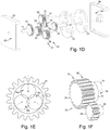
- Fig 1E illustrates non-uniform placement of the second shafts 14a-14c on the associated offset members 33a-33c that is required for the first exemplary embodiment to be assemble-able.
- the requirement for non-uniform second shaft 14 placement depends on the particular pitch diameters and spacing of the associated engaging members.
- Fig 1F illustrates a detail view of an offset member 33 and an engaged coupling member 34.
- the offset member 33 has a large face width, a portion of which is engaged by the first stage 51, and a portion of which is engaged by the second stage 52.
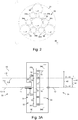
- Fig 2 illustrates a second exemplary embodiment of the present invention which is similar to the first exemplary embodiment except two redundant coupling members 34a, 34b simultaneously engage the second central member 32 and each offset member 33. Both coupling members 34a, 34b are depicted with uniform pitch diameters. If the coupling members 34a, 34b are non-uniform, non-uniform coupling distances 42 are required for the associated coupling members 34a, 34b.
- Figs 3A-3B illustrate a third exemplary embodiment of the present invention which is similar to the first exemplary embodiment except each coupling member 34 is a stepped coupling member comprising a first step 34a, and a second step 34b.
- An offset member 33 engages each first step 34a and the second central member 32 simultaneously engages all second steps 34b.
- the second carrier 22 is located in front of the offset members 33 and the second central member 32 is located behind the first carrier 21, which is a floating carrier.
- Fig 4 illustrates a fourth exemplary embodiment of the present invention which is similar to the first exemplary embodiment except each coupling member 34 is a stepped coupling member comprising a first step 34a and a second step 34b.
- the first central member 31 is a ring which simultaneously engages all first steps 34a and each second step 34b simultaneously engages the second central member 32 and an offset member 33.
- Fig 5 illustrates a fifth exemplary embodiment of the present invention which is similar to the first exemplary embodiment except it further comprises a third carrier 23 which is integral with all coupling axes 10 and comprises a third rotation axis 5.
- the third rotation axis 5 and the central axis 0 are co-axial and rotatably coupled
- the second carrier 22 is located in front of the offset members 33
- each first shaft 13 and the associated offset member 33 are non-co-axial
- the first carrier axis 1 and the central axis 0 are non-co-axial.
- Fig 6 illustrates a sixth exemplary embodiment of the present invention which is similar to the first exemplary embodiment except each offset member 33 is a stepped offset member comprising a first step 33a, and a second step 33b. All first steps 33a simultaneously engage the first central member 31 and each second step 33b engages a coupling member 34.
- Figs 7A-7C illustrate a seventh exemplary embodiment of the present invention which is similar to the sixth exemplary embodiment except all offset members 33 are stepped offset members 33 comprising a gear first step 33a and a pulley second step 33b, all coupling members 34 are flexible coupling members 34, there are no coupling axes 10, and the second central member 32 is a stepped pulley.
- Fig 7B depicts the second stage 52 of the seventh exemplary embodiment.
- Fig 7C illustrates a detail view of the second central member 32 comprising three steps 32a-32c which each engage a different flexible coupling member 34. All steps 32a-32c have a common pitch diameter and are included to avoid mechanical interference.
- Fig 8 illustrates an eighth exemplary embodiment of the present invention which is an alternative configuration of the second stage 52 of the seventh exemplary embodiment. It comprises four offset members 33b and two serpentine coupling members 34, each simultaneously engaging the second central member 32 and two offset members 33.
- Fig 9 illustrates a ninth exemplary embodiment of the present invention which is an alternative configuration of the second stage 52 of the seventh exemplary embodiment. It comprises three offset members 33b, one of which further comprises a third step 33c. A serpentine engaging member 34a simultaneously engages all offset member second steps 33b. A flexible engaging member 34b simultaneously engages the second central member 32 and the offset member third step 33c. Providing the second central member 32 and the offset member third step 33c with a variable pitch diameter results in an infinitely variable speed ratio.
- Figs 10A-10B illustrate a tenth exemplary embodiment of the present invention which is similar to the first exemplary embodiment except the first central member 31 is absent, the first and second carriers 21, 22 are located in front of the offset members 33, and the first drive-shaft 11 and the first carrier 21 are co-axial and integral.
- the absence of the first central member 31 eliminates the first stage 51 altogether, and leaves only the second stage 52, which is a Coupled Orbitless gearbox.
- Fig 11 illustrates an eleventh exemplary embodiment of the present invention which is similar to the tenth exemplary embodiment except the first drive-shaft 11 and second carrier 22 are co-axial and integral. This embodiment provides offset first and second drive-shafts 11, 12.
- Fig 12 illustrates a twelfth exemplary embodiment of the present invention which is similar to the first exemplary embodiment except the first central member 31 is a ring, the first central member 31 and an additional second drive-shaft 12a are co-axial and integral, the first and second carriers 21, 22 are located in front of the offset members 33, and the first drive-shaft 11 and the first carrier 21 are co-axial and integral.
- the first and second stages 51, 52 each depict a Coupled Orbitless gearbox which both reside in a common plane and each comprise a second drive-shaft 12a, 12b which each deliver a different speed ratio, and together depict a 2-speed Coupled Orbitless gearbox.
- the first through ninth exemplary embodiments each comprise a first stage 51 comprising a first central member 31 and offset members 33 which are engaged whereby they counter-rotate with respect to the first carrier 21.
- Each of these exemplary embodiments depict an Orbitless first stage 51.
- the first through twelfth exemplary embodiments each comprise a second stage 52 comprising a second central member 32 and offset members 33 which are engaged whereby they rotate in a common direction with respect to the first carrier 21.
- Each of these exemplary embodiments depict a Coupled Orbitless second stage 52.
- R 1 , R 1 ', R 2 , and R 2 ' are defined where T C is the number of turns of the carriers 21, 22, 23, which all rotate in unison with respect to the reference member 30.
- R 1 T 1 T C : 1
- R 1 ′ T C T 1 : 1
- R 2 T 2 T C : 1
- R 2 ′ T C T 2 : 1
- Speed ratios are computed from P 1 , P 2 , P o , P a , and P b which are the pitch diameters of the first central member 31, second central member 32, offset members 33, coupling member first steps 34a, and coupling member second steps 34b, respectively. Only stepped coupling members 34 alter the speed ratio.
- an engaging member is a gear with a module of 1
- the pitch diameter is equal to the number of teeth.
- each coupling member 34 is a stepped pinion gear.
- P 1 25
- P 2 19
- P o 20
- P a 19
- P b 18
- a fourth example considers the second stage 52 of the ninth exemplary embodiment illustrated in Fig 9 .
- the second central member 32 and the offset member third step 33c have a variable pitch radius defined by the ratio N.
- the pitch diameters of the offset member 33c and the second central member 32 may be manipulated to maintain a constant length of the flexible coupling member 34b.
- N 1 2 ⁇ 1
- R 2 ′ 2 : 1 ⁇ ⁇ : 1
- N 1 ⁇ 2
- R 2 ′ ⁇ : 1 ⁇ ⁇ 1 : 1
- a fifth example considers the tenth and eleventh exemplary embodiments illustrated in Figs 10-11 which depict a Coupled Orbitless gearbox.
- P 2 21
- P o 20
- Certain exemplary embodiments disclosed herein have a number of advantageous properties. Certain exemplary embodiments comprise two gearing stages with a single set of carriers which provides low cost and complexity.
- Certain exemplary embodiments provide a high speed ratio in a small volume. Certain exemplary embodiments provide multiple speed ratios.
- Certain exemplary embodiments provide an infinitely variable speed ratio. Certain exemplary embodiments provide low pitch velocity and bearing speed which may accommodate a high input speed.
- Certain exemplary embodiments comprise flexible coupling members with a high contact ratio and high torque capacity.
- Certain exemplary embodiments comprise offset or co-axial drive axes.
Landscapes
- Engineering & Computer Science (AREA)
- General Engineering & Computer Science (AREA)
- Mechanical Engineering (AREA)
- Retarders (AREA)
- General Details Of Gearings (AREA)
Description
- The disclosure herein relates to a gearbox comprising a plurality of gears or other engaging members. More particularly, it relates to an apparatus providing a drive member that rotates at a different rate as a driven member.
- An Orbitless gearbox (
US 9,970,509 B2; published on 16 March 2017 US 627,977; published on 4 July 1899 ) but produces a lower speed ratio. It is, therefore, more energy efficient, but requires a greater volume for a given speed ratio. - A Coupled Orbitless gearbox comprises coupling members which engage the central and offset members whereby they rotate in a common direction. This amplifies and inverts the speed ratio so that the roles of the input and output members are interchanged. Since the carriers are the output of an Orbitless reduction gearbox and the input of a Coupled Orbitless reduction gearbox, integrating an Orbitless first stage with a Coupled Orbitless second stage, allows a common set of carriers and offset members to be shared by both stages. A Hybrid Orbitless gearbox combines the superior efficiency and highspeed characteristics of an Orbitless gearbox with the high reduction ratio of a Coupled Orbitless gearbox.
-
GB 2,221,278 A -
US 4,896,567 describes a planetary transmission mechanism and device of involute gears with compound small tooth-difference having two internal gear drives, an eccentric shaft with two eccentric axles and a rotational delivery mechanism with the gear pair's tooth-difference optimally equal to 5 to 8 teeth. The internal gear drives comprise at least two pairs of gears, the planetary gear of each gear drive being rotatably sleeved on a respective eccentric axle of the eccentric shaft. -
US 2004/0018203 A1 describes a two-stage differential cycloidal speed reducer with a high reduction ratio, including: a plurality of supporting crank shafts; an input shaft including a first crank shaft portion and a second crank shaft portion; a first cycloidal gear provided on the first crank shaft portion; a second cycloidal gear provided on the second crank shaft portion and connected with the first cycloidal gear through the supporting crank shafts; a plurality of first ring pins provided around the outer circumference of the first cycloidal gear and in sliding contact with a plurality of teeth on the periphery of the first cycloidal gear; a first annular gear with the plurality of first ring pins; a plurality of second ring pins provided around the outer circumference of the second cycloidal gear and being in sliding contact with a plurality of teeth on the periphery of the second cycloidal gear; and a second annular gear with the plurality of second ring pins. -
US 4,762,025 describes a two-stage differential cycloidal speed reducer with a high reduction ratio, including: a plurality of supporting crank shafts; an input shaft including a first crank shaft portion and a second crank shaft portion; a first cycloidal gear provided on the first crank shaft portion; a second cycloidal gear provided on the second crank shaft portion and connected with the first cycloidal gear through the supporting crank shafts; a plurality of first ring pins provided around the outer circumference of the first cycloidal gear and in sliding contact with a plurality of teeth on the periphery of the first cycloidal gear; a first annular gear with the plurality of first ring pins; a plurality of second ring pins provided around the outer circumference of the second cycloidal gear and being in sliding contact with a plurality of teeth on the periphery of the second cycloidal gear; and a second annular gear with the plurality of second ring pins. - Certain exemplary embodiments comprise a reference member, a first and second carrier, a second central member, one or more offset members, one or more coupling members, and a number of coupling axes equal to the number of coupling members. The second central member and all offset and coupling members are engaging members. The reference member comprises a central axis and a first and second carrier axis. Each carrier comprises a rotation axis and a number of offset axes equal to the number of offset members. Each offset member comprises a first and second member axis. All axes are parallel. The first and second carrier axes and all associated first and second member axes are spaced apart by the carrier distance. Each offset axis and the associated rotation axis are spaced apart by an offset distance. All offset axes are arranged circumferentially around the associated rotation axis. The second central member and the central axis, the first rotation axis and the first carrier axis, the second rotation axis and the second carrier axis, each first member axis and a different first offset axis, each second member axis and a different second offset axis, and each coupling member and a different coupling axis, are co-axial and rotatably coupled. The coupling axes are arranged whereby the coupling members simultaneously engage the second central member and all offset members. Certain exemplary embodiments further comprise a first central member which is an engaging member which is co-axial and rotatably coupled with the central axis.
- In certain exemplary embodiments, the first central member simultaneously engages all offset members.
- In certain exemplary embodiments, the first central member simultaneously engages all coupling members.
- In certain exemplary embodiments, each offset member is a stepped engaging member.
- In certain exemplary embodiments, each coupling member is a stepped engaging member.
- In certain exemplary embodiments, one of the first or second carriers and all coupling axes are integral. The associated carrier axis and the central axis are co-axial.
- Certain exemplary embodiments further comprise a third carrier comprising a third rotation axis. The third carrier and all coupling axes are integral. The third rotation axis and the central axis are co-axial and rotatably coupled.
- Certain exemplary embodiments further comprise a variable speed ratio between the second central member and the offset members.
- Certain exemplary embodiments comprise a reference member, a first and second carrier, a first and second central member, one or more offset members, and one or more coupling members. The first and second central member and all offset and coupling members are engaging members. The reference member comprises a central axis and a first and second carrier axis. Each carrier comprises a rotation axis and a number of offset axes equal to the number of offset members. Each offset member comprises a first and second member axis. All axes are parallel. The first and second carrier axes and all associated first and second member axes are spaced apart by the carrier distance. Each offset axis and the associated rotation axis are spaced apart by an offset distance. All offset axes are arranged circumferentially around the associated rotation axis. The first central member and the central axis, the second central member and the central axis, the first rotation axis and the first carrier axis, the second rotation axis and the second carrier axis, each first member axis and a different first offset axis, and each second member axis and a different second offset axis, are co-axial and rotatably coupled. The first central member simultaneously engages all offset members. The coupling members simultaneously engage the second central member and all offset members.
- In certain exemplary embodiments, each coupling member is a stepped engaging member.
- Certain exemplary embodiments further comprise a variable speed ratio between the second central member and the offset members.
- In certain exemplary embodiments, a reference member, a first and second carrier, a first and second central member, one or more offset members, and one or more coupling members are provided. The first and second central members and all offset and coupling members are provided with an engaging means. The reference member is provided with a central axis and a first and second carrier axis. Each carrier is provided with a rotation axis and a number of offset axes equal to the number of offset members. Each offset member is provided with a first and second member axis. All axes are located whereby they are all parallel. The first and second carrier axes and all associated first and second member axes are spaced apart by the carrier distance. Each offset axis and the associated rotation axis are spaced apart by an offset distance. All offset axes are arranged circumferentially around the associated rotation axis. The first central member and the central axis, the second central member and the central axis, the first rotation axis and first carrier axis, the second rotation axis and second carrier axis, each first member axis and a different first offset axis, and each second member axis and a different second offset axis, are co-axially located and rotatably coupled. The coupling members are simultaneously engaged with the second central member and all offset members.
- In certain exemplary embodiments, the first central member is simultaneously engaged with all offset members.
- In certain exemplary embodiments, the first central member is simultaneously engaged with all coupling members.
- In certain exemplary embodiments, each offset member is provided with a first engaging step and a second engaging step.
- In certain exemplary embodiments, each coupling member is provided with a first engaging step and a second engaging step.
- In certain exemplary embodiments, one of the first or second carriers is provided with a number of coupling axes equal to the number of coupling members. Each coupling member and a different coupling axis are co-axially located and rotatably coupled. The associated carrier axis and the central axis are co-axially located.
- In certain exemplary embodiments, a third carrier is provided which is provided with a third rotation axis and a number of coupling axes equal to the number of coupling members. Each coupling member and a different coupling axis, and the third rotation axis and the central axis, are co-axially located and rotatably coupled.
- In certain exemplary embodiments, a variable speed ratio is provided between the second central member and the offset members.
-
-
Figs 1A-1D are respectively, a schematic side view, two partial front views, and an exploded perspective view, in accordance with a first exemplary embodiment depicting the present invention comprising gear engaging members. -
Figs 1E-1F are respectively a rear view of an offset member, and a perspective view of an engaged offset and coupling member, in accordance with the first exemplary embodiment of the present invention. -
Fig 2 is a partial front view in accordance with a second exemplary embodiment depicting the present invention comprising two coupling members engaging each offset member. -
Figs 3A-3B are respectively, a schematic side view and an exploded perspective view, in accordance with a third exemplary embodiment depicting the present invention comprising stepped coupling members. -
Fig 4 is a schematic side view in accordance with a fourth exemplary embodiment depicting the present invention comprising a ring first central member engaging stepped coupling members. -
Fig 5 is a schematic side view in accordance with a fifth exemplary embodiment depicting the present invention comprising three non-co-axial carriers. -
Fig 6 is a schematic side view in accordance with a sixth exemplary embodiment depicting the present invention comprising stepped offset members. -
Figs 7A-7B are respectively, an exploded perspective view and a partial front view, in accordance with a seventh exemplary embodiment depicting the present invention comprising flexible coupling members. -
Fig 7C is a perspective view of a stepped second central member, in accordance with the seventh exemplary embodiment of the present invention. -
Fig 8 is a partial front view in accordance with an eighth exemplary embodiment depicting the present invention comprising two serpentine coupling members, each engaging a pair of adjacent offset members. -
Fig 9 is a partial front view in accordance with a ninth exemplary embodiment depicting the present invention comprising one flexible coupling member and one serpentine coupling member. -
Figs 10A-10B are respectively, a schematic side view and an exploded perspective view in accordance with a tenth exemplary embodiment depicting the present invention comprising an integral first drive-shaft and first carrier. -
Fig 11 is a schematic side view in accordance with an eleventh exemplary embodiment depicting the present invention comprising an integral first drive-shaft and second carrier, providing offset first and second drive-shafts. -
Fig 12 is a schematic side view in accordance with a twelfth exemplary embodiment depicting the present invention comprising multiple second drive-shafts, each providing a different speed ratio. - A gear, sprocket, chain, pulley, belt, cable, friction or magnetic coupling, or any other member that engages and transmits energy to a mate is defined as an engaging member. An engaging member that engages and transmits energy between two or more engaging members is defined as a coupling member.
- A chain, belt, cable, or any other coupling member that changes shape while transmitting energy is defined as a flexible coupling member.
- A flexible coupling member that simultaneously couples three or more engaging members is defined as a serpentine coupling member.
- A flexible coupling comprising two counter-acting, pre-loaded cables that are fixedly attached to two pulleys is defined as a capstan cable coupling.
- An engaging member that engages on its exterior surface is defined as a pinion. An engaging member that engages on its interior surface is defined as a ring.
- A member that is coupled to an axis by three or more encircling engaging members but by no other mechanical means is defined as floating.
- Two parallel, offset shafts integrated into a common member is defined as a crankshaft. An apparatus that scales the relative speed and torque of a drive and driven member is defined as a gearbox, whether or not it comprises any gears.
- A gearbox that reduces velocity and amplifies torque is defined as a reduction gearbox. A gearbox that amplifies velocity and reduces torque is defined as an overdrive gearbox. A gearbox that may function as either a reduction or an overdrive gearbox is defined as back-drivable.
- A gearbox comprising a reference member, two offset carriers, a central member and one or more crankshaft offset members is defined as an Orbitless gearbox.
- An Orbitless gearbox further comprising one or more coupling members is defined as a Coupled Orbitless gearbox.
- A gearbox which integrates two or more Orbitless and/or Coupled Orbitless gearboxes with a common set of carriers is defined as a Hybrid Orbitless gearbox.
- Wherever possible, the same reference numerals are used throughout the accompanying drawings and descriptions to refer to the same or similar parts. Components such as bearings, retainers and fasteners that do not substantially contribute to the understanding of the invention are neglected for the sake of simplicity.
- Although spur gears, pulleys, belts and cables are depicted in the accompanying drawings, it is understood that many other engaging means would suffice, such as conical, radial, offset, spiral, helical, double helical, herring-bone, or roller tooth gears, friction or magnetic couplings, and chain drives. It is also understood that associated gears may comprise any face width, tooth profile, pressure angle, or module and may be made from metal, plastic, or any other appropriate material.
- Although a male shaft and female race are used to depict a rotatable coupling in the accompanying drawings, it is understood that any other means will suffice, such as antifriction bearings, bushings, or low friction coatings, materials, surface treatments or lubricants. It is also understood that the male and female members of a rotatable coupling may often be interchanged.
- Although a shaft is used to depict a drive or driven member in the accompanying drawings, it is understood that any other means will suffice, such as an engaging member, a keyed, splined, or threaded hole, or a magnetic or electrostatic coupling.
- Although three or four offset
members 33 are depicted in certain accompanying drawings, it is understood that any number of offsetmembers 33 may be included, as long as they do not mechanically interfere. - Although two stages are depicted sharing a common set of carriers in certain accompanying drawings, it is understood that any number of stages may be included, as long as they do not mechanically interfere.
- It is understood that multiple gearboxes may be joined in series or in parallel or combined with any other type of gearbox to provide a desired speed ratio or other characteristic.
- It is understood that a back-drivable gearbox may provide either a reduction or an overdrive ratio by interchanging the roles of its drive and driven members. In fact, the roles of the reference member, drive member and driven member may all be interchanged to obtain a desired speed ratio, or to cause the drive and driven members to rotate in the same or opposite directions. Similarly, if any one is used as a drive member and the remaining two are used as driven members, a differential mechanism is obtained. Reduction, overdrive, differential, and reverse gearboxes are all contemplated.
- It is understood that any one of the
reference member 30, the firstcentral member 31, the secondcentral member 32, an offsetmember 33, acoupling member 34, or the first, second, orthird carrier - Although certain exemplary embodiments depict the first drive-
shaft 11 and the first orsecond carrier carriers shaft 11 could be integral with any of the first, second orthird carriers - It is understood that the individual offset
members 33 may have non-uniform first and second member axes 8, 9 as long as the associated first and second offsetaxes 6, 7 are similarly non-uniform, although additional vibration may result. - Although certain exemplary embodiments depict all offset
axes 6, 7 as being circumferentially equally spaced around the associatedrotation axis 3, 4, it is understood that they may be unequally spaced, although additional vibration may result. - Although certain exemplary embodiments depict a first, second or
third carrier case 30 and the exterior of the associatedcarrier third carrier case 30. Similarly, the first or secondcentral member - A representative sample of embodiments is included in the accompanying drawings for exemplary purposes only. A great number of kinematic arrangements, types of engaging members, and combinations of disclosed features are also contemplated. The scope of the present invention is not limited to the embodiments included but spans all possible combinations anticipated by the specification and claims.
-
Figs 1A-1F illustrate a first exemplary embodiment of the present invention providing a reduction ratio between a first drive-shaft 11 and a second drive-shaft 12. - The first exemplary embodiment comprises a
reference member 30, afirst carrier 21, asecond carrier 22, a firstcentral member 31, a secondcentral member 32, three offsetmembers 33, and threecoupling members 34. - The
reference member 30 acts as the case of the gearbox and comprises a central axis 0, a first carrier axis 1, and asecond carrier axis 2, all of which are parallel. The first carrier axis 1 and the central axis 0 are co-axial. Thesecond carrier axis 2 and the central axis 0 are spaced apart by acarrier distance 40. - The
first carrier 21 comprises a first rotation axis 3, three first offset axes 6, and three coupling axes 10. All first offset axes 6 are circumferentially equally spaced. Each first offset axis 6 and the first rotation axis 3 are spaced apart by an offsetdistance 41. All coupling axes 10 are circumferentially equally spaced. Eachcoupling axis 10 and the first rotation axis 3 are spaced apart by acoupling distance 42. - The
second carrier 22 comprises asecond rotation axis 4 and three second offsetaxes 7. All second offsetaxes 7 are circumferentially equally spaced. Each second offsetaxis 7 and thesecond rotation axis 4 are spaced apart by the offsetdistance 41. - The first rotation axis 3 and the first carrier axis 1 are co-axial and rotatably coupled. The
second rotation axis 4 and thesecond carrier axis 2 are co-axial and rotatably coupled. - Each offset
member 33 comprises a co-axialfirst shaft 13 defining a first member axis 8, and an offsetsecond shaft 14 defining a second member axis 9, which are parallel, spaced apart by thecarrier distance 40, and together define a crankshaft. Eachcoupling member 34 comprises aco-axial coupling shaft 15. - Each first member axis 8 and a different first offset axis 6 are co-axial and rotatably coupled. Each second member axis 9 and a different second offset
axis 7 are co-axial and rotatably coupled. Eachcoupling shaft 15 and adifferent coupling axis 10 are co-axial and rotatably coupled. - The first
central member 31 and first drive-shaft 11 are co-axial and integral. The secondcentral member 32 and second drive-shaft 12 are co-axial and integral. The firstcentral member 31 and the central axis 0 are co-axial and rotatably coupled. The secondcentral member 32 and the central axis 0 are co-axial and rotatably coupled. - The first
central member 31, secondcentral member 32, all offsetmembers 33, and allcoupling members 34 are pinion gears. The firstcentral member 31 simultaneously engages all offsetmembers 33. Eachcoupling member 34 simultaneously engages the secondcentral member 32 and a different offsetmember 33. Together, thecoupling members 34 co-operate to simultaneously engage the secondcentral member 32 and all offsetmembers 33. - The first
central member 31, all offsetmembers 33, and thecarriers first stage 51 which is an Orbitless gearbox. The secondcentral member 32, all offsetmembers 33, allcoupling members 34, and thecarriers second stage 52 which is a Coupled Orbitless gearbox. The offsetmembers 33 andcarriers second stages -
Fig 1E illustrates non-uniform placement of thesecond shafts 14a-14c on the associated offsetmembers 33a-33c that is required for the first exemplary embodiment to be assemble-able. The requirement for non-uniformsecond shaft 14 placement depends on the particular pitch diameters and spacing of the associated engaging members. -
Fig 1F illustrates a detail view of an offsetmember 33 and an engagedcoupling member 34. The offsetmember 33 has a large face width, a portion of which is engaged by thefirst stage 51, and a portion of which is engaged by thesecond stage 52. -
Fig 2 illustrates a second exemplary embodiment of the present invention which is similar to the first exemplary embodiment except tworedundant coupling members central member 32 and each offsetmember 33. Bothcoupling members coupling members coupling members -
Figs 3A-3B illustrate a third exemplary embodiment of the present invention which is similar to the first exemplary embodiment except eachcoupling member 34 is a stepped coupling member comprising afirst step 34a, and asecond step 34b. An offsetmember 33 engages eachfirst step 34a and the secondcentral member 32 simultaneously engages allsecond steps 34b. In addition, thesecond carrier 22 is located in front of the offsetmembers 33 and the secondcentral member 32 is located behind thefirst carrier 21, which is a floating carrier. -
Fig 4 illustrates a fourth exemplary embodiment of the present invention which is similar to the first exemplary embodiment except eachcoupling member 34 is a stepped coupling member comprising afirst step 34a and asecond step 34b. The firstcentral member 31 is a ring which simultaneously engages allfirst steps 34a and eachsecond step 34b simultaneously engages the secondcentral member 32 and an offsetmember 33. -
Fig 5 illustrates a fifth exemplary embodiment of the present invention which is similar to the first exemplary embodiment except it further comprises athird carrier 23 which is integral with allcoupling axes 10 and comprises a third rotation axis 5. The third rotation axis 5 and the central axis 0 are co-axial and rotatably coupled, thesecond carrier 22 is located in front of the offsetmembers 33, eachfirst shaft 13 and the associated offsetmember 33 are non-co-axial, and the first carrier axis 1 and the central axis 0 are non-co-axial. -
Fig 6 illustrates a sixth exemplary embodiment of the present invention which is similar to the first exemplary embodiment except each offsetmember 33 is a stepped offset member comprising afirst step 33a, and asecond step 33b. Allfirst steps 33a simultaneously engage the firstcentral member 31 and eachsecond step 33b engages acoupling member 34. -
Figs 7A-7C illustrate a seventh exemplary embodiment of the present invention which is similar to the sixth exemplary embodiment except all offsetmembers 33 are stepped offsetmembers 33 comprising a gearfirst step 33a and a pulleysecond step 33b, allcoupling members 34 areflexible coupling members 34, there are no coupling axes 10, and the secondcentral member 32 is a stepped pulley. -
Fig 7B depicts thesecond stage 52 of the seventh exemplary embodiment. -
Fig 7C illustrates a detail view of the secondcentral member 32 comprising threesteps 32a-32c which each engage a differentflexible coupling member 34. Allsteps 32a-32c have a common pitch diameter and are included to avoid mechanical interference. -
Fig 8 illustrates an eighth exemplary embodiment of the present invention which is an alternative configuration of thesecond stage 52 of the seventh exemplary embodiment. It comprises four offsetmembers 33b and twoserpentine coupling members 34, each simultaneously engaging the secondcentral member 32 and two offsetmembers 33. -
Fig 9 illustrates a ninth exemplary embodiment of the present invention which is an alternative configuration of thesecond stage 52 of the seventh exemplary embodiment. It comprises three offsetmembers 33b, one of which further comprises athird step 33c. Aserpentine engaging member 34a simultaneously engages all offset member second steps 33b. A flexible engagingmember 34b simultaneously engages the secondcentral member 32 and the offset memberthird step 33c. Providing the secondcentral member 32 and the offset memberthird step 33c with a variable pitch diameter results in an infinitely variable speed ratio. -
Figs 10A-10B illustrate a tenth exemplary embodiment of the present invention which is similar to the first exemplary embodiment except the firstcentral member 31 is absent, the first andsecond carriers members 33, and the first drive-shaft 11 and thefirst carrier 21 are co-axial and integral. The absence of the firstcentral member 31 eliminates thefirst stage 51 altogether, and leaves only thesecond stage 52, which is a Coupled Orbitless gearbox. -
Fig 11 illustrates an eleventh exemplary embodiment of the present invention which is similar to the tenth exemplary embodiment except the first drive-shaft 11 andsecond carrier 22 are co-axial and integral. This embodiment provides offset first and second drive-shafts -
Fig 12 illustrates a twelfth exemplary embodiment of the present invention which is similar to the first exemplary embodiment except the firstcentral member 31 is a ring, the firstcentral member 31 and an additional second drive-shaft 12a are co-axial and integral, the first andsecond carriers members 33, and the first drive-shaft 11 and thefirst carrier 21 are co-axial and integral. The first andsecond stages shaft - As illustrated by the arrows in
Fig 1B , the first through ninth exemplary embodiments each comprise afirst stage 51 comprising a firstcentral member 31 and offsetmembers 33 which are engaged whereby they counter-rotate with respect to thefirst carrier 21. - Each of these exemplary embodiments depict an Orbitless
first stage 51. - As illustrated by the arrows in
Figs 1C ,2 ,7B, 8 and 9 , the first through twelfth exemplary embodiments each comprise asecond stage 52 comprising a secondcentral member 32 and offsetmembers 33 which are engaged whereby they rotate in a common direction with respect to thefirst carrier 21. Each of these exemplary embodiments depict a Coupled Orbitlesssecond stage 52. - In each of the examples herein, two gearbox speed ratios, R and R' are defined where T1 is the number of turns of the first drive-
shaft 11 and T2 is the corresponding number of turns of the second drive-shaft 12, all with respect to thereference member 30.
- For each of the first and
second stages carriers reference member 30.
- A Hybrid Orbitless gearbox comprising an Orbitless
first stage 51 and a Coupled Orbitlesssecond stage 52 provides the following reduction ratio:
- Speed ratios are computed from P1, P2, Po, Pa, and Pb which are the pitch diameters of the first
central member 31, secondcentral member 32, offsetmembers 33, coupling memberfirst steps 34a, and coupling membersecond steps 34b, respectively. Only steppedcoupling members 34 alter the speed ratio. When an engaging member is a gear with a module of 1, the pitch diameter is equal to the number of teeth. - In each
first stage 51, the firstcentral member 31 and all offsetmembers 33 are engaged whereby they counter-rotate and provide the following speed ratios:
- In each
second stage 52, the secondcentral member 32 and all offsetmembers 33 are engaged whereby they rotate in a common direction and provide the following speed ratios:
- The following speed ratios result when the following conditions are met:


- The following speed ratios result when the
coupling members 34 are stepped:
- The following speed ratios result when the following conditions are met:


- A first example considers the first and second exemplary embodiments illustrated in
Figs 1-2 where each couplingmember 34 is a non-stepped pinion gear.

- A second example considers the third exemplary embodiment illustrated in
Fig 3 where each couplingmember 34 is a stepped pinion gear.

- A third example considers the seventh exemplary embodiment illustrated in
Fig 7 where all engaging members in thesecond stage 52 are pulleys and belts. The absence of gear teeth makes a very high reduction ratio practical. Note that if P2= Po then R=R2'=∞:1.

- A fourth example considers the
second stage 52 of the ninth exemplary embodiment illustrated inFig 9 . The secondcentral member 32 and the offset memberthird step 33c have a variable pitch radius defined by the ratio N. In practice, the pitch diameters of the offsetmember 33c and the secondcentral member 32 may be manipulated to maintain a constant length of theflexible coupling member 34b. The variable pitchsecond stage 52 provides the following speed ratios:
- When N varies from 0.5 to 1, R2' varies from 2:1 to ∞:1, which corresponds to a stopped second drive-shaft 12 (T2=0 for any Tc). When N varies from 1 to 2, R2' varies from ∞:1 to -1:1 which corresponds to a direction reversal of the second drive-
shaft 12.

- A fifth example considers the tenth and eleventh exemplary embodiments illustrated in
Figs 10-11 which depict a Coupled Orbitless gearbox.

- The exemplary embodiments disclosed herein have a number of advantageous properties. Certain exemplary embodiments comprise two gearing stages with a single set of carriers which provides low cost and complexity.
- Certain exemplary embodiments provide a high speed ratio in a small volume. Certain exemplary embodiments provide multiple speed ratios.
- Certain exemplary embodiments provide an infinitely variable speed ratio. Certain exemplary embodiments provide low pitch velocity and bearing speed which may accommodate a high input speed.
- Certain exemplary embodiments comprise flexible coupling members with a high contact ratio and high torque capacity.
- Certain exemplary embodiments comprise offset or co-axial drive axes.
- Other advantages are apparent from the disclosure herein.
| 0 - central axis | 21 - first carrier |
| 1 - first carrier axis | 22 - second carrier |
| 2 - second carrier axis | 23 - third carrier |
| 3 - first rotation axis | 30 - reference member |
| 4 - second rotation axis | 31 - first central member |
| 5 - third rotation axis | 32 - second central member |
| 6 - first offset axis | 33 - offset member |
| 7 - second offset axis | 34 -coupling member |
| 8 - first member axis | 40 - carrier distance |
| 9 - second member axis | 41 - offset distance |
| 10 - coupling axis | 42 - coupling distance |
| 11 - first drive-shaft | 51 - first stage |
| 12 - second drive-shaft | 52 - second stage |
| 13 - first shaft | 53 - front |
| 14 - second shaft | 54 - rear |
| 15 - coupling shaft |
Claims (20)
- An apparatus comprising:a reference member (30), a first and second carrier (21, 22), a second central member (32), one or more offset members (33), and one or more coupling members (34);the second central member (32) and all offset (33), and coupling members (34) are configured to engage to transmit energy;the reference member (30) comprises a central axis (0) and a first and second carrier axis (1, 2);the first carrier (21) comprises a first rotation axis (3) and a number of first offset axes (6) equal to the number of offset members (33);the second carrier (22) comprises a second rotation axis (4) and a number of second offset axes (7) equal to the number of offset members (33);each offset member (33) comprises a first and second member axis (8, 9);and wherein:all axes (0, 1, 2, 3, 4, 6, 7, 8, 9) are parallel;the first and second carrier axes (1, 2) are spaced apart by a carrier distance (40);for each offset member (33), the first and second member axes (8, 9) are spaced apart by the carrier distance (40);each first offset axis (6) and the first rotation axis (3) are spaced apart by an offset distance (41);each second offset axis (7) and the second rotation axis (4) are spaced apart by the offset distance (41);all first offset axes (6) are arranged circumferentially around the first rotation axis (3);all second offset axes (7) are arranged circumferentially around the second rotation axis (4);the second central member (32) is co-axial and rotatably coupled with the central axis (0);the first rotation axis (3) is co-axial and rotatably coupled with the first carrier axis (1);the second rotation axis (4) is co-axial and rotatably coupled with the second carrier axis (2);each first member axis (8) is co-axial and rotatably coupled with a different first offset axis (6);each second member axis (9) is co-axial and rotatably coupled with a different second offset axis (7);and each coupling member (34) simultaneously engages the second central member (32) and a different offset member (33).
- The apparatus of claim 1 further comprising a number of coupling axes (10) equal to the number of coupling members (34),
wherein each coupling member (34) is co-axial and rotatably coupled with a different coupling axis (10). - The apparatus of claim 1 or claim 2 further comprising a first central member (31) which is configured to engage to transmit energy and which is co-axial and rotatably coupled with the central axis (0).
- The apparatus of claim 3 wherein the first central member (31) simultaneously engages all offset members (33).
- The apparatus of claim 3 wherein the first central member (31) simultaneously engages all coupling members (34).
- The apparatus of claim 1 wherein each offset member (33) is a stepped engaging member.
- The apparatus of claim 1 wherein each coupling member (34) is a stepped engaging member.
- The apparatus of claim 2 wherein one of the first or second carriers (21, 22), and all coupling axes (10) are integral, and the associated carrier axis (1, 2) and the central axis (0) are co-axial.
- The apparatus of claim 2 further comprising a third carrier (23) comprising a third rotation axis (5), and wherein the third carrier (23) and all coupling axes (10) are integral, and the third rotation axis (5) and the central axis (0) are co-axial and rotatably coupled.
- The apparatus of claim 1 further comprising a variable speed ratio between the second central member (32) and the offset members (33).
- A method comprising:providing a reference member (30), a first and second carrier (21, 22), a second central member (32), one or more offset members (33), and one or more coupling members (34);the second central member (32) and all offset (33) and coupling members (34) being configured to engage to transmit energy;providing the reference member (30) with a central axis (0) and a first and second carrier axis (1, 2);providing the first carrier (21) with a first rotation axis (3), and a number of first offset axes (6) equal to the number of offset members (33);providing the second carrier (22) with a second rotation axis (4), and a number of second offset axes (7) equal to the number of offset members (33);providing each offset member (33) with a first and second member axis (8, 9);locating all axes (0, 1, 2, 3, 4, 6, 7, 8, 9) whereby they are all parallel;spacing the first and second carrier axes (1, 2) apart by a carrier distance (40);spacing the first member axis (8) and the second member axis (9) of each offset member (33) apart by the carrier distance (40);spacing each first offset axis (6) and the first rotation axis (3) apart by an offset distance (41);spacing each second offset axis (7) and the second rotation axis (4) apart by the offset distance (41);arranging all first offset axes (6) circumferentially around the first rotation axis (3);arranging all second offset axes (7) circumferentially around the second rotation axis (4);co-axially locating and rotatably coupling the second central member (32) with the central axis (0);co-axially locating and rotatably coupling the first rotation axis (3) with the first carrier axis (1);co-axially locating and rotatably coupling the second rotation axis (4) with the second carrier axis (2);co-axially locating and rotatably coupling each first member axis (8) with a different first offset axis (6);co-axially locating and rotatably coupling each second member axis (9) with a different second offset axis (7);and simultaneously engaging each coupling member (34) with the second central member (32) and a different offset member (33).
- The method of claim 11 further comprising:providing a number of coupling axes (10) equal to the number of coupling members (34), andco-axially locating and rotatably coupling each coupling member (34) with a different coupling axis (10).
- The method of claim 11 or claim 12 further providing a first central member (31), the first central member (31) being configured to engage to transmit energy, and co-axially locating and rotatably coupling the first central member (31) with the central axis (0).
- The method of claim 13 simultaneously engaging the first central member (31) with all offset members (33).
- The method of claim 13 simultaneously engaging the first central member (31) with all coupling members (34).
- The method of claim 11 further providing each offset member (33) with a first engaging step and a second engaging step.
- The method of claim 11 further providing each coupling member (34) with a first engaging step and a second engaging step.
- The method of claim 11 further providing one of the first or second carriers (21, 22) with a number of coupling axes (10) equal to the number of coupling members (34), co-axially locating and rotatably coupling each coupling member (34) and a different coupling axis (10), and co-axially locating the associated carrier axis (1, 2) and the central axis (0).
- The method of claim 11 further providing a third carrier (23), providing the third carrier (23) with a third rotation axis (5) and a number of coupling axes (10) equal to the number of coupling members (34), co-axially locating and rotatably coupling each coupling member (34) and a different coupling axis (10), and co-axially locating and rotatably coupling the third rotation axis (5) and the central axis (0).
- The method of claim 11 further providing a variable speed ratio between the second central member (32) and the offset members (33).
Applications Claiming Priority (2)
| Application Number | Priority Date | Filing Date | Title |
|---|---|---|---|
| US201462048776P | 2014-09-10 | 2014-09-10 | |
| PCT/CA2015/050861 WO2016037271A1 (en) | 2014-09-10 | 2015-09-08 | Hybrid orbitless gearbox |
Publications (3)
| Publication Number | Publication Date |
|---|---|
| EP3191736A1 EP3191736A1 (en) | 2017-07-19 |
| EP3191736A4 EP3191736A4 (en) | 2018-07-11 |
| EP3191736B1 true EP3191736B1 (en) | 2020-05-06 |
Family
ID=55458214
Family Applications (1)
| Application Number | Title | Priority Date | Filing Date |
|---|---|---|---|
| EP15839548.3A Active EP3191736B1 (en) | 2014-09-10 | 2015-09-08 | Hybrid orbitless gearbox |
Country Status (4)
| Country | Link |
|---|---|
| US (1) | US10247278B2 (en) |
| EP (1) | EP3191736B1 (en) |
| CN (1) | CN107208745B (en) |
| WO (1) | WO2016037271A1 (en) |
Families Citing this family (5)
| Publication number | Priority date | Publication date | Assignee | Title |
|---|---|---|---|---|
| US20190353240A1 (en) * | 2017-02-22 | 2019-11-21 | Orbitless Drives Inc. | Multi-Speed Orbitless Drive |
| CN110177957A (en) * | 2017-11-29 | 2019-08-27 | 无轨道驾驶公司 | Coaxial trackless transmission device |
| WO2021115119A1 (en) * | 2019-12-13 | 2021-06-17 | Inovo Robotics (Hk) Limited | A gear transmission device |
| DE102023125803A1 (en) * | 2023-09-22 | 2025-03-27 | Minebea Mitsumi Inc. | Epicyclic gear |
| DE102023125797A1 (en) * | 2023-09-22 | 2025-03-27 | Minebea Mitsumi Inc. | Actuator device |
Family Cites Families (19)
| Publication number | Priority date | Publication date | Assignee | Title |
|---|---|---|---|---|
| FR1053098A (en) | 1952-03-27 | 1954-01-29 | Improvements to planetary speed reducers | |
| US2950635A (en) * | 1959-07-15 | 1960-08-30 | Daco Instr Company | Miniaturized gear reducer |
| US4762025A (en) * | 1986-07-31 | 1988-08-09 | Lew Hyok S | All orbiting gear planetary drive |
| CN1009749B (en) | 1987-07-18 | 1990-09-26 | 湖南省机械研究所 | Mixed small tooth difference involute gear planetary transmission mechanism and device |
| CN1018567B (en) | 1988-06-30 | 1992-10-07 | 湖南省机械研究所 | Mixed few-differential spider reducer and speed variator |
| US5544539A (en) | 1995-01-23 | 1996-08-13 | Geartechnic Corporation | Gear drive with eccentric shift mechanism |
| DE10254527A1 (en) | 2002-11-22 | 2004-06-09 | Multibrid Entwicklungsges. Mbh | Process for low-loss torque transmission in planetary gears |
| DE102005049366A1 (en) * | 2005-10-11 | 2007-04-19 | Mbm Technologie Gmbh | Motor-driven vehicle with a transmission for an accessory |
| DE102006058133A1 (en) | 2006-12-09 | 2008-06-19 | Zf Friedrichshafen Ag | Actuator for roll stabilization |
| US7641579B2 (en) * | 2007-04-19 | 2010-01-05 | Junkers John K | Eccentric gear mechanism and method of transfering turning force thereby |
| US7794355B2 (en) * | 2007-05-15 | 2010-09-14 | Snap-On Incorporated | Planetary gear set centering ring |
| KR100969369B1 (en) * | 2007-12-14 | 2010-07-09 | 현대자동차주식회사 | Planetary gear set |
| DE102008063044B4 (en) * | 2008-12-23 | 2012-01-05 | Aerodyn Engineering Gmbh | planetary gear |
| US8721490B2 (en) * | 2011-04-25 | 2014-05-13 | Gear Drive Zt, L.L.C. | Planetary drive system |
| CN103477118A (en) | 2012-02-24 | 2013-12-25 | 日锻汽门株式会社 | Planetary gear reducer |
| CN103453117A (en) | 2012-06-05 | 2013-12-18 | 无锡市灵龙机械设备有限公司 | Novel gear box |
| CN103542041B (en) | 2012-07-13 | 2016-02-24 | 财团法人工业技术研究院 | Differential two-stage high-reduction-ratio cycloidal speed reducer |
| US20140200109A1 (en) | 2013-01-14 | 2014-07-17 | Leo James Stocco | Planetary Gear Pump |
| US20140315679A1 (en) * | 2013-04-22 | 2014-10-23 | GM Global Technology Operations LLC | Stacked planetary gear set |
-
2015
- 2015-09-08 US US15/511,214 patent/US10247278B2/en not_active Expired - Fee Related
- 2015-09-08 EP EP15839548.3A patent/EP3191736B1/en active Active
- 2015-09-08 WO PCT/CA2015/050861 patent/WO2016037271A1/en not_active Ceased
- 2015-09-08 CN CN201580059678.XA patent/CN107208745B/en not_active Expired - Fee Related
Non-Patent Citations (1)
| Title |
|---|
| None * |
Also Published As
| Publication number | Publication date |
|---|---|
| CN107208745A (en) | 2017-09-26 |
| CN107208745B (en) | 2019-05-31 |
| EP3191736A4 (en) | 2018-07-11 |
| US20170292589A1 (en) | 2017-10-12 |
| EP3191736A1 (en) | 2017-07-19 |
| US10247278B2 (en) | 2019-04-02 |
| WO2016037271A1 (en) | 2016-03-17 |
Similar Documents
| Publication | Publication Date | Title |
|---|---|---|
| US10247278B2 (en) | Hybrid orbitless gearbox | |
| US20090227415A1 (en) | Torque Balancing Gearbox | |
| US9243700B1 (en) | Coupled worm planetary gear continuously variable ratio transmission | |
| US9587711B2 (en) | Anti-backlash gear | |
| US20120046140A1 (en) | Planetary harmonic differential transmission | |
| US9605742B2 (en) | Large-ratio strain wave gearing speed changing apparatus | |
| EP3143305B1 (en) | Orbitless gearbox | |
| US20030132088A1 (en) | Conveyor drive system and motor built-in reducer therefor | |
| US8979697B2 (en) | Large-ratio speed changing apparatus | |
| CN102016349B (en) | Transmission and differential device | |
| EP3120044B1 (en) | Hub planetary belt transmission | |
| US20090036244A1 (en) | Mechanical speed reducer by chain | |
| US20190353240A1 (en) | Multi-Speed Orbitless Drive | |
| US12007023B2 (en) | Belt for continuously variable transmission | |
| US20200263764A1 (en) | Coaxial orbitless drive | |
| US20190360562A1 (en) | Gearless Speed Reducer | |
| RU2635753C2 (en) | Wind turbine with gearbox of single-stage speed multiplier with high gear ratio | |
| EP2988024A2 (en) | Large-ratio strain wave gearing speed changing apparatus | |
| EP3538787A1 (en) | Coaxial orbitless drive | |
| RU2389922C2 (en) | Method of torque transfer and variator tooth gear | |
| US20090005204A1 (en) | Mechanical speed reducer by belt | |
| WO2018084812A1 (en) | Two stage speed reducer | |
| RU2674915C1 (en) | Planetary gear | |
| JP2016118232A (en) | Power transmission device | |
| PL240626B1 (en) | Chain or belt transmission |
Legal Events
| Date | Code | Title | Description |
|---|---|---|---|
| STAA | Information on the status of an ep patent application or granted ep patent |
Free format text: STATUS: THE INTERNATIONAL PUBLICATION HAS BEEN MADE |
|
| PUAI | Public reference made under article 153(3) epc to a published international application that has entered the european phase |
Free format text: ORIGINAL CODE: 0009012 |
|
| STAA | Information on the status of an ep patent application or granted ep patent |
Free format text: STATUS: REQUEST FOR EXAMINATION WAS MADE |
|
| 17P | Request for examination filed |
Effective date: 20170330 |
|
| AK | Designated contracting states |
Kind code of ref document: A1 Designated state(s): AL AT BE BG CH CY CZ DE DK EE ES FI FR GB GR HR HU IE IS IT LI LT LU LV MC MK MT NL NO PL PT RO RS SE SI SK SM TR |
|
| AX | Request for extension of the european patent |
Extension state: BA ME |
|
| DAV | Request for validation of the european patent (deleted) | ||
| DAX | Request for extension of the european patent (deleted) | ||
| REG | Reference to a national code |
Ref country code: DE Ref legal event code: R079 Ref document number: 602015052474 Country of ref document: DE Free format text: PREVIOUS MAIN CLASS: F16H0001020000 Ipc: F16H0001280000 |
|
| A4 | Supplementary search report drawn up and despatched |
Effective date: 20180611 |
|
| RIC1 | Information provided on ipc code assigned before grant |
Ipc: F16H 57/08 20060101ALI20180605BHEP Ipc: F16H 1/28 20060101AFI20180605BHEP |
|
| RAP1 | Party data changed (applicant data changed or rights of an application transferred) |
Owner name: ORBITLESS DRIVES INC |
|
| RIN1 | Information on inventor provided before grant (corrected) |
Inventor name: STOCCO, LEO J. |
|
| RAP1 | Party data changed (applicant data changed or rights of an application transferred) |
Owner name: ORBITLESS DRIVES INC. |
|
| RAP1 | Party data changed (applicant data changed or rights of an application transferred) |
Owner name: ORBITLESS DRIVES INC. |
|
| GRAP | Despatch of communication of intention to grant a patent |
Free format text: ORIGINAL CODE: EPIDOSNIGR1 |
|
| STAA | Information on the status of an ep patent application or granted ep patent |
Free format text: STATUS: GRANT OF PATENT IS INTENDED |
|
| INTG | Intention to grant announced |
Effective date: 20191205 |
|
| GRAS | Grant fee paid |
Free format text: ORIGINAL CODE: EPIDOSNIGR3 |
|
| GRAA | (expected) grant |
Free format text: ORIGINAL CODE: 0009210 |
|
| STAA | Information on the status of an ep patent application or granted ep patent |
Free format text: STATUS: THE PATENT HAS BEEN GRANTED |
|
| AK | Designated contracting states |
Kind code of ref document: B1 Designated state(s): AL AT BE BG CH CY CZ DE DK EE ES FI FR GB GR HR HU IE IS IT LI LT LU LV MC MK MT NL NO PL PT RO RS SE SI SK SM TR |
|
| REG | Reference to a national code |
Ref country code: GB Ref legal event code: FG4D |
|
| REG | Reference to a national code |
Ref country code: CH Ref legal event code: EP Ref country code: CH Ref legal event code: NV Representative=s name: MICHELI AND CIE SA, CH Ref country code: AT Ref legal event code: REF Ref document number: 1267251 Country of ref document: AT Kind code of ref document: T Effective date: 20200515 |
|
| REG | Reference to a national code |
Ref country code: IE Ref legal event code: FG4D |
|
| REG | Reference to a national code |
Ref country code: DE Ref legal event code: R096 Ref document number: 602015052474 Country of ref document: DE |
|
| REG | Reference to a national code |
Ref country code: LT Ref legal event code: MG4D |
|
| REG | Reference to a national code |
Ref country code: NL Ref legal event code: MP Effective date: 20200506 |
|
| PG25 | Lapsed in a contracting state [announced via postgrant information from national office to epo] |
Ref country code: IS Free format text: LAPSE BECAUSE OF FAILURE TO SUBMIT A TRANSLATION OF THE DESCRIPTION OR TO PAY THE FEE WITHIN THE PRESCRIBED TIME-LIMIT Effective date: 20200906 Ref country code: PT Free format text: LAPSE BECAUSE OF FAILURE TO SUBMIT A TRANSLATION OF THE DESCRIPTION OR TO PAY THE FEE WITHIN THE PRESCRIBED TIME-LIMIT Effective date: 20200907 Ref country code: FI Free format text: LAPSE BECAUSE OF FAILURE TO SUBMIT A TRANSLATION OF THE DESCRIPTION OR TO PAY THE FEE WITHIN THE PRESCRIBED TIME-LIMIT Effective date: 20200506 Ref country code: SE Free format text: LAPSE BECAUSE OF FAILURE TO SUBMIT A TRANSLATION OF THE DESCRIPTION OR TO PAY THE FEE WITHIN THE PRESCRIBED TIME-LIMIT Effective date: 20200506 Ref country code: LT Free format text: LAPSE BECAUSE OF FAILURE TO SUBMIT A TRANSLATION OF THE DESCRIPTION OR TO PAY THE FEE WITHIN THE PRESCRIBED TIME-LIMIT Effective date: 20200506 Ref country code: NO Free format text: LAPSE BECAUSE OF FAILURE TO SUBMIT A TRANSLATION OF THE DESCRIPTION OR TO PAY THE FEE WITHIN THE PRESCRIBED TIME-LIMIT Effective date: 20200806 Ref country code: GR Free format text: LAPSE BECAUSE OF FAILURE TO SUBMIT A TRANSLATION OF THE DESCRIPTION OR TO PAY THE FEE WITHIN THE PRESCRIBED TIME-LIMIT Effective date: 20200807 |
|
| PGFP | Annual fee paid to national office [announced via postgrant information from national office to epo] |
Ref country code: LU Payment date: 20200709 Year of fee payment: 6 Ref country code: FR Payment date: 20200716 Year of fee payment: 6 Ref country code: IE Payment date: 20200710 Year of fee payment: 6 |
|
| PG25 | Lapsed in a contracting state [announced via postgrant information from national office to epo] |
Ref country code: BG Free format text: LAPSE BECAUSE OF FAILURE TO SUBMIT A TRANSLATION OF THE DESCRIPTION OR TO PAY THE FEE WITHIN THE PRESCRIBED TIME-LIMIT Effective date: 20200806 Ref country code: LV Free format text: LAPSE BECAUSE OF FAILURE TO SUBMIT A TRANSLATION OF THE DESCRIPTION OR TO PAY THE FEE WITHIN THE PRESCRIBED TIME-LIMIT Effective date: 20200506 Ref country code: RS Free format text: LAPSE BECAUSE OF FAILURE TO SUBMIT A TRANSLATION OF THE DESCRIPTION OR TO PAY THE FEE WITHIN THE PRESCRIBED TIME-LIMIT Effective date: 20200506 Ref country code: HR Free format text: LAPSE BECAUSE OF FAILURE TO SUBMIT A TRANSLATION OF THE DESCRIPTION OR TO PAY THE FEE WITHIN THE PRESCRIBED TIME-LIMIT Effective date: 20200506 |
|
| PGFP | Annual fee paid to national office [announced via postgrant information from national office to epo] |
Ref country code: BE Payment date: 20200709 Year of fee payment: 6 |
|
| REG | Reference to a national code |
Ref country code: AT Ref legal event code: MK05 Ref document number: 1267251 Country of ref document: AT Kind code of ref document: T Effective date: 20200506 |
|
| PG25 | Lapsed in a contracting state [announced via postgrant information from national office to epo] |
Ref country code: AL Free format text: LAPSE BECAUSE OF FAILURE TO SUBMIT A TRANSLATION OF THE DESCRIPTION OR TO PAY THE FEE WITHIN THE PRESCRIBED TIME-LIMIT Effective date: 20200506 Ref country code: NL Free format text: LAPSE BECAUSE OF FAILURE TO SUBMIT A TRANSLATION OF THE DESCRIPTION OR TO PAY THE FEE WITHIN THE PRESCRIBED TIME-LIMIT Effective date: 20200506 |
|
| PG25 | Lapsed in a contracting state [announced via postgrant information from national office to epo] |
Ref country code: DK Free format text: LAPSE BECAUSE OF FAILURE TO SUBMIT A TRANSLATION OF THE DESCRIPTION OR TO PAY THE FEE WITHIN THE PRESCRIBED TIME-LIMIT Effective date: 20200506 Ref country code: AT Free format text: LAPSE BECAUSE OF FAILURE TO SUBMIT A TRANSLATION OF THE DESCRIPTION OR TO PAY THE FEE WITHIN THE PRESCRIBED TIME-LIMIT Effective date: 20200506 Ref country code: EE Free format text: LAPSE BECAUSE OF FAILURE TO SUBMIT A TRANSLATION OF THE DESCRIPTION OR TO PAY THE FEE WITHIN THE PRESCRIBED TIME-LIMIT Effective date: 20200506 Ref country code: SM Free format text: LAPSE BECAUSE OF FAILURE TO SUBMIT A TRANSLATION OF THE DESCRIPTION OR TO PAY THE FEE WITHIN THE PRESCRIBED TIME-LIMIT Effective date: 20200506 Ref country code: ES Free format text: LAPSE BECAUSE OF FAILURE TO SUBMIT A TRANSLATION OF THE DESCRIPTION OR TO PAY THE FEE WITHIN THE PRESCRIBED TIME-LIMIT Effective date: 20200506 Ref country code: RO Free format text: LAPSE BECAUSE OF FAILURE TO SUBMIT A TRANSLATION OF THE DESCRIPTION OR TO PAY THE FEE WITHIN THE PRESCRIBED TIME-LIMIT Effective date: 20200506 Ref country code: CZ Free format text: LAPSE BECAUSE OF FAILURE TO SUBMIT A TRANSLATION OF THE DESCRIPTION OR TO PAY THE FEE WITHIN THE PRESCRIBED TIME-LIMIT Effective date: 20200506 Ref country code: IT Free format text: LAPSE BECAUSE OF FAILURE TO SUBMIT A TRANSLATION OF THE DESCRIPTION OR TO PAY THE FEE WITHIN THE PRESCRIBED TIME-LIMIT Effective date: 20200506 |
|
| PGFP | Annual fee paid to national office [announced via postgrant information from national office to epo] |
Ref country code: CH Payment date: 20201002 Year of fee payment: 6 |
|
| REG | Reference to a national code |
Ref country code: DE Ref legal event code: R097 Ref document number: 602015052474 Country of ref document: DE |
|
| PG25 | Lapsed in a contracting state [announced via postgrant information from national office to epo] |
Ref country code: PL Free format text: LAPSE BECAUSE OF FAILURE TO SUBMIT A TRANSLATION OF THE DESCRIPTION OR TO PAY THE FEE WITHIN THE PRESCRIBED TIME-LIMIT Effective date: 20200506 Ref country code: SK Free format text: LAPSE BECAUSE OF FAILURE TO SUBMIT A TRANSLATION OF THE DESCRIPTION OR TO PAY THE FEE WITHIN THE PRESCRIBED TIME-LIMIT Effective date: 20200506 |
|
| PLBE | No opposition filed within time limit |
Free format text: ORIGINAL CODE: 0009261 |
|
| STAA | Information on the status of an ep patent application or granted ep patent |
Free format text: STATUS: NO OPPOSITION FILED WITHIN TIME LIMIT |
|
| 26N | No opposition filed |
Effective date: 20210209 |
|
| PG25 | Lapsed in a contracting state [announced via postgrant information from national office to epo] |
Ref country code: MC Free format text: LAPSE BECAUSE OF FAILURE TO SUBMIT A TRANSLATION OF THE DESCRIPTION OR TO PAY THE FEE WITHIN THE PRESCRIBED TIME-LIMIT Effective date: 20200506 |
|
| PG25 | Lapsed in a contracting state [announced via postgrant information from national office to epo] |
Ref country code: SI Free format text: LAPSE BECAUSE OF FAILURE TO SUBMIT A TRANSLATION OF THE DESCRIPTION OR TO PAY THE FEE WITHIN THE PRESCRIBED TIME-LIMIT Effective date: 20200506 |
|
| PGFP | Annual fee paid to national office [announced via postgrant information from national office to epo] |
Ref country code: GB Payment date: 20210924 Year of fee payment: 7 Ref country code: DE Payment date: 20210917 Year of fee payment: 7 |
|
| REG | Reference to a national code |
Ref country code: CH Ref legal event code: PL |
|
| REG | Reference to a national code |
Ref country code: BE Ref legal event code: MM Effective date: 20210930 |
|
| PG25 | Lapsed in a contracting state [announced via postgrant information from national office to epo] |
Ref country code: TR Free format text: LAPSE BECAUSE OF FAILURE TO SUBMIT A TRANSLATION OF THE DESCRIPTION OR TO PAY THE FEE WITHIN THE PRESCRIBED TIME-LIMIT Effective date: 20200506 Ref country code: MT Free format text: LAPSE BECAUSE OF FAILURE TO SUBMIT A TRANSLATION OF THE DESCRIPTION OR TO PAY THE FEE WITHIN THE PRESCRIBED TIME-LIMIT Effective date: 20200506 Ref country code: CY Free format text: LAPSE BECAUSE OF FAILURE TO SUBMIT A TRANSLATION OF THE DESCRIPTION OR TO PAY THE FEE WITHIN THE PRESCRIBED TIME-LIMIT Effective date: 20200506 |
|
| PG25 | Lapsed in a contracting state [announced via postgrant information from national office to epo] |
Ref country code: MK Free format text: LAPSE BECAUSE OF FAILURE TO SUBMIT A TRANSLATION OF THE DESCRIPTION OR TO PAY THE FEE WITHIN THE PRESCRIBED TIME-LIMIT Effective date: 20200506 |
|
| PG25 | Lapsed in a contracting state [announced via postgrant information from national office to epo] |
Ref country code: LU Free format text: LAPSE BECAUSE OF NON-PAYMENT OF DUE FEES Effective date: 20210908 Ref country code: IE Free format text: LAPSE BECAUSE OF NON-PAYMENT OF DUE FEES Effective date: 20210908 Ref country code: FR Free format text: LAPSE BECAUSE OF NON-PAYMENT OF DUE FEES Effective date: 20210930 Ref country code: BE Free format text: LAPSE BECAUSE OF NON-PAYMENT OF DUE FEES Effective date: 20210930 |
|
| PG25 | Lapsed in a contracting state [announced via postgrant information from national office to epo] |
Ref country code: LI Free format text: LAPSE BECAUSE OF NON-PAYMENT OF DUE FEES Effective date: 20210930 Ref country code: CH Free format text: LAPSE BECAUSE OF NON-PAYMENT OF DUE FEES Effective date: 20210930 |
|
| REG | Reference to a national code |
Ref country code: DE Ref legal event code: R119 Ref document number: 602015052474 Country of ref document: DE |
|
| GBPC | Gb: european patent ceased through non-payment of renewal fee |
Effective date: 20220908 |
|
| PG25 | Lapsed in a contracting state [announced via postgrant information from national office to epo] |
Ref country code: DE Free format text: LAPSE BECAUSE OF NON-PAYMENT OF DUE FEES Effective date: 20230401 |
|
| PG25 | Lapsed in a contracting state [announced via postgrant information from national office to epo] |
Ref country code: GB Free format text: LAPSE BECAUSE OF NON-PAYMENT OF DUE FEES Effective date: 20220908 |