EP3191274B1 - Method for manufacturing plywood and automated core veneer layer - Google Patents
Method for manufacturing plywood and automated core veneer layer Download PDFInfo
- Publication number
- EP3191274B1 EP3191274B1 EP15839910.5A EP15839910A EP3191274B1 EP 3191274 B1 EP3191274 B1 EP 3191274B1 EP 15839910 A EP15839910 A EP 15839910A EP 3191274 B1 EP3191274 B1 EP 3191274B1
- Authority
- EP
- European Patent Office
- Prior art keywords
- veneer
- pieces
- core
- conveyor
- core veneer
- Prior art date
- Legal status (The legal status is an assumption and is not a legal conclusion. Google has not performed a legal analysis and makes no representation as to the accuracy of the status listed.)
- Active
Links
- 239000011120 plywood Substances 0.000 title claims description 21
- 238000004519 manufacturing process Methods 0.000 title claims description 18
- 238000000034 method Methods 0.000 title claims description 14
- 230000003287 optical effect Effects 0.000 claims description 4
- 239000011162 core material Substances 0.000 description 133
- 238000010586 diagram Methods 0.000 description 4
- 239000003292 glue Substances 0.000 description 3
- 239000000853 adhesive Substances 0.000 description 2
- 230000001070 adhesive effect Effects 0.000 description 2
- 238000010276 construction Methods 0.000 description 2
- 230000003213 activating effect Effects 0.000 description 1
- 230000004048 modification Effects 0.000 description 1
- 238000012986 modification Methods 0.000 description 1
- 238000003825 pressing Methods 0.000 description 1
- 230000008569 process Effects 0.000 description 1
- 239000002994 raw material Substances 0.000 description 1
- 230000004044 response Effects 0.000 description 1
Images


Classifications
-
- B—PERFORMING OPERATIONS; TRANSPORTING
- B27—WORKING OR PRESERVING WOOD OR SIMILAR MATERIAL; NAILING OR STAPLING MACHINES IN GENERAL
- B27D—WORKING VENEER OR PLYWOOD
- B27D1/00—Joining wood veneer with any material; Forming articles thereby; Preparatory processing of surfaces to be joined, e.g. scoring
- B27D1/04—Joining wood veneer with any material; Forming articles thereby; Preparatory processing of surfaces to be joined, e.g. scoring to produce plywood or articles made therefrom; Plywood sheets
-
- B—PERFORMING OPERATIONS; TRANSPORTING
- B32—LAYERED PRODUCTS
- B32B—LAYERED PRODUCTS, i.e. PRODUCTS BUILT-UP OF STRATA OF FLAT OR NON-FLAT, e.g. CELLULAR OR HONEYCOMB, FORM
- B32B38/00—Ancillary operations in connection with laminating processes
- B32B38/18—Handling of layers or the laminate
- B32B38/1825—Handling of layers or the laminate characterised by the control or constructional features of devices for tensioning, stretching or registration
- B32B38/1833—Positioning, e.g. registration or centering
-
- B—PERFORMING OPERATIONS; TRANSPORTING
- B32—LAYERED PRODUCTS
- B32B—LAYERED PRODUCTS, i.e. PRODUCTS BUILT-UP OF STRATA OF FLAT OR NON-FLAT, e.g. CELLULAR OR HONEYCOMB, FORM
- B32B41/00—Arrangements for controlling or monitoring lamination processes; Safety arrangements
-
- B—PERFORMING OPERATIONS; TRANSPORTING
- B65—CONVEYING; PACKING; STORING; HANDLING THIN OR FILAMENTARY MATERIAL
- B65H—HANDLING THIN OR FILAMENTARY MATERIAL, e.g. SHEETS, WEBS, CABLES
- B65H3/00—Separating articles from piles
- B65H3/08—Separating articles from piles using pneumatic force
- B65H3/0808—Suction grippers
- B65H3/0816—Suction grippers separating from the top of pile
- B65H3/0833—Suction grippers separating from the top of pile and acting on the front part of the articles relatively to the final separating direction
-
- B—PERFORMING OPERATIONS; TRANSPORTING
- B32—LAYERED PRODUCTS
- B32B—LAYERED PRODUCTS, i.e. PRODUCTS BUILT-UP OF STRATA OF FLAT OR NON-FLAT, e.g. CELLULAR OR HONEYCOMB, FORM
- B32B21/00—Layered products comprising a layer of wood, e.g. wood board, veneer, wood particle board
- B32B21/13—Layered products comprising a layer of wood, e.g. wood board, veneer, wood particle board all layers being exclusively wood
-
- B—PERFORMING OPERATIONS; TRANSPORTING
- B32—LAYERED PRODUCTS
- B32B—LAYERED PRODUCTS, i.e. PRODUCTS BUILT-UP OF STRATA OF FLAT OR NON-FLAT, e.g. CELLULAR OR HONEYCOMB, FORM
- B32B21/00—Layered products comprising a layer of wood, e.g. wood board, veneer, wood particle board
- B32B21/14—Layered products comprising a layer of wood, e.g. wood board, veneer, wood particle board comprising wood board or veneer
-
- B—PERFORMING OPERATIONS; TRANSPORTING
- B32—LAYERED PRODUCTS
- B32B—LAYERED PRODUCTS, i.e. PRODUCTS BUILT-UP OF STRATA OF FLAT OR NON-FLAT, e.g. CELLULAR OR HONEYCOMB, FORM
- B32B2607/00—Walls, panels
-
- B—PERFORMING OPERATIONS; TRANSPORTING
- B32—LAYERED PRODUCTS
- B32B—LAYERED PRODUCTS, i.e. PRODUCTS BUILT-UP OF STRATA OF FLAT OR NON-FLAT, e.g. CELLULAR OR HONEYCOMB, FORM
- B32B37/00—Methods or apparatus for laminating, e.g. by curing or by ultrasonic bonding
- B32B37/14—Methods or apparatus for laminating, e.g. by curing or by ultrasonic bonding characterised by the properties of the layers
- B32B37/16—Methods or apparatus for laminating, e.g. by curing or by ultrasonic bonding characterised by the properties of the layers with all layers existing as coherent layers before laminating
- B32B37/18—Methods or apparatus for laminating, e.g. by curing or by ultrasonic bonding characterised by the properties of the layers with all layers existing as coherent layers before laminating involving the assembly of discrete sheets or panels only
-
- B—PERFORMING OPERATIONS; TRANSPORTING
- B65—CONVEYING; PACKING; STORING; HANDLING THIN OR FILAMENTARY MATERIAL
- B65H—HANDLING THIN OR FILAMENTARY MATERIAL, e.g. SHEETS, WEBS, CABLES
- B65H2553/00—Sensing or detecting means
- B65H2553/40—Sensing or detecting means using optical, e.g. photographic, elements
- B65H2553/42—Cameras
-
- B—PERFORMING OPERATIONS; TRANSPORTING
- B65—CONVEYING; PACKING; STORING; HANDLING THIN OR FILAMENTARY MATERIAL
- B65H—HANDLING THIN OR FILAMENTARY MATERIAL, e.g. SHEETS, WEBS, CABLES
- B65H2701/00—Handled material; Storage means
- B65H2701/10—Handled articles or webs
- B65H2701/19—Specific article or web
- B65H2701/1938—Veneer sheet
Definitions
- the present invention generally relates to the field of plywood manufacturing, and more specifically to a method for manufacturing plywood according to the preamble of claim 1 and an automated core veneer layer for manufacturing plywood according to the preamble of claim 4.
- Such a method is known from US 3 580 778 A and such an automated core veneer layer is known from US 2011/057384 A1 .
- Plywood consists of three basic components, a face sheet, a back sheet, and a core material, also referred to as cross band, disposed in between the face sheet and the back sheet at 90 degrees.
- plywood is made by manually placing one or more layers of core material in between the face sheet and the back sheet.
- At least one layer of the core material is made of multiple pieces of veneer that are smaller than the face and back sheet in at least one dimension.
- the smaller pieces of veneer are manually fed onto a conveyor system by a first operator and then are manually taken off of the conveyor and placed on either the face or back sheet by a second operator.
- the second operator ensures that the veneers pieces are precisely placed with no laps or gaps. This process is not only labor intensive, but it also limits the speed at which the plywood can be manufactured.
- an automated core veneer feeder and automated core veneer layer for manufacturing plywood are desired.
- the invention provides a method for manufacturing plywood according to claim 1.
- the method for manufacturing plywood includes receiving a face sheet on a main conveyor, manually feeding a plurality of pieces of core veneer onto a veneer conveyor by an automated core veneer feeder, detecting each of the plurality of pieces of core veneer on the veneer conveyor by one or more sensors in the veneer conveyor, and calculating, by a processor based on data received from the one or more sensors, a position, a length and a width of each of the plurality of pieces of core veneer on the veneer conveyor.
- the method also includes aligning the plurality of pieces of core veneer by one or more actuators, wherein the one or more actuators are directed by the processor to individually move the each of the plurality of pieces of core veneer on the veneer conveyor in a plurality of directions, wherein the aligning ensures that there are no gaps between adjacent pieces of core veneer and that the adjacent pieces of core veneer do not overlap.
- the method also includes removing the plurality of pieces of core veneer from the veneer conveyor after the plurality of pieces of core veneer have been properly aligned, and placing the plurality of pieces of core veneer onto the face sheet.
- an automated core veneer feeder includes a pair of sweed rolls that receive pieces of core veneer and to feed the pieces of core veneer onto a veneer conveyor, a vision system that scans a stack of core veneers and identifies a size and placement of each of the core veneers on the stack and a vacuum feeder assembly that lifts individual pieces of core veneer off of the stack by turning selectively activating one or more vacuum cups.
- the automated core veneer feeder also includes a processor that receives input signals from the vision system and at least one of a controller or one or more sensors in the veneer conveyor and that responsively controls the pair of sweed rolls and the vacuum feeder assembly.
- the invention also provides an automated core veneer layer according to claim 4.
- the automated core veneer layer includes a veneer conveyor having one or more sensors configured to detect a plurality of pieces of core veneer on the veneer conveyor and a processor that receives input signal from the one or more sensors and responsively calculates a position and a size of the plurality of pieces of core veneer on the veneer conveyor.
- the automated core veneer layer also includes one or more actuators that individually move each of the plurality of pieces of core veneer on the veneer conveyor into a desired position, wherein the one or more actuators are controlled by the processor to: individually move the each of the plurality of pieces of core veneer on the veneer conveyor in a plurality of directions to ensure that there are no gaps between adjacent pieces of core veneer and that the adjacent pieces of core veneer do not overlap; place the plurality of pieces of core veneer onto a face sheet after the plurality of pieces of core veneer have been properly aligned.
- the system 100 includes a main conveyor 102 which extends through the entire manufacturing line.
- the system 100 also includes a face sheet apparatus 104, disposed near a first end of the main conveyor 102, which is configured to place face sheets 106 onto the main conveyor 102.
- the face sheets 106 are then moved through a glue application station 108 where an adhesive is applied to an upper surface of the face sheets 106.
- the system 100 includes an automated core veneer feeder 110 which feeds pieces of core veneer 111 onto a veneer conveyor 112.
- the veneer conveyor 112 moves the pieces of core veneer 111 to an assembly station where an operator 114 places the pieces of core veneer 111 on top of the face sheets 106.
- the veneer conveyor 112 moves the pieces of core veneer 111 to and places the pieces of core veneer 111 on top of the face sheets 106; the operator 114 then adjusts the alignment of the pieces of core veneer 111 as needed.
- the operator 114 ensures that there are no gaps between the adjacent pieces of core veneer 111 and that the adjacent pieces of core veneer 111 do not overlap when positioned on the face sheet 106.
- the operator 114 may use a controller 116 to control the operation of the automated core veneer feeder 110.
- the controller 116 is used to instruct the automated core veneer feeder 110 to feed additional pieces of core veneer 111 onto the veneer conveyor 112.
- the controller 116 may be a remote that includes one or more buttons.
- the controller 116 may be a pedal controller or an optical sensor that the operator can use with one of his hands or feet to signal that additional pieces of core veneer 111 need to be dispensed onto the veneer conveyor 112.
- the operation of the automated core veneer feeder 110 may be completely automated.
- one or more sensors 118 may be disposed along the veneer conveyor 112 and the sensors 118 can be used to determine the number of pieces of core veneer 111 on the veneer conveyor 112.
- the automated core veneer feeder 110 can be configured to monitor the sensors 118 and to automatically feed additional pieces of core veneer 111 onto the veneer conveyor 112 if the sensors 118 indicate that the number of pieces of core veneer 111 on the veneer conveyor 112 is below a threshold minimum amount.
- the automated core veneer feeder 110 can be configured to monitor the sensors 118 and to continuously feed additional pieces of core veneer 111 onto the veneer conveyor 112 until the sensors 118 indicate that the number of pieces of core veneer 111 on the veneer conveyor 112 has reached a desired amount.
- the main conveyor 102 moves the face sheets 106 with the properly positioned pieces of core veneer 111 through a second glue application station 108 and an adhesive is applied to an upper surface of pieces of core veneer 111.
- the main conveyor 102 moves the face sheets 106 with the properly positioned pieces of core veneer 111 to a back sheet apparatus 120, which places a back sheet 122 on top of the face sheets 106 and the pieces of core veneer 111.
- back sheet 122 is placed the loosely assembled plywood panel(s) are cut into 99" individual sheets, stacked and prepared for pressing.
- Figure 1 illustrates a three-ply panel construction; face, core veneer and back.
- the automated core veneer feeder 200 includes a pair of sweed rolls 202 that are configured to receive pieces of core veneer 212 and to feed the pieces of core veneer 212 onto a veneer conveyor.
- the pieces of core veneer 212 are stored in a stack 210 adjacent to the sweed rolls 202.
- the automated core veneer feeder 200 includes a vision system 208 that is configured to scan the top of the stack 210 of core veneers 212 and to be able to identify the size and placement of each of the core veneers 212 on the top of the stack 210.
- the automated core veneer feeder 200 includes a vacuum feeder assembly 204 that is configured to lift individual pieces of core veneer 212 off of the stack 210 by turning on and off one or more vacuum cups 206.
- the vacuum feeder assembly 204 is capable of picking up multiple pieces of core veneer 212 from the top of the stack 210 at one time using the vacuum cups 206. Once the vacuum feeder assembly 204 lifts the pieces of core veneer 212 from the top of the stack 210, the vacuum feeder assembly 204 moves the pieces of core veneer 212 towards the sweed rolls 202. After the pieces of core veneer 212 make contact with the sweed rolls 202, the vacuum cups 206 will release the pieces of core veneer 212, allowing the pieces of core veneer 212 to be fed through the sweed rolls 202 and on to a veneer conveyor.
- the automated core veneer feeder 310 includes a processor 312, a vision system 314, sweed rolls 316 and a vacuum feeder assembly 318.
- the processor 312 may be a simple processor such as an ASIC or FPGA or it may be a traditional microprocessor.
- the processor 312 may receive input signals from one or more sensors 302, a controller 304 and/or the vision system 314 and responsively control the operation of the vacuum feeder assembly 318 and/or the sweed rolls 316.
- the processor 312 receives a signal from either the controller 304 or the one or more sensors 302 which indicates that additional pieces of core veneer need to be placed on the veneer conveyor. In response to receiving such a signal, the processor 312 uses the vision system 314 to identify individual pieces of core veneer located on the core veneer stack. Once the individual pieces of core veneer have been identified, the processor 312 instructs the vacuum feeder assembly 318 to lift the identified individual pieces of core veneer with one or more vacuum cups 320. After the pieces of core veneer have been lifted, the processor 312 instructs the vacuum feeder assembly 318 to move the individual pieces of core veneer to contact the sweed rolls 316. In exemplary embodiments, the processor 312 may also control the operation of the sweed rolls 316 including when the sweed rolls 316 will be active and the speed of the sweed rolls 316.
- FIG 4 a system 400 for manufacturing plywood having an automated core veneer feeder and an automated core veneer layer in accordance with an exemplary embodiment is shown.
- the system 400 is largely the same as the system 100 shown in Figures 1A and 1B and the portions of the system 400 that are the same will not be discussed in further detail.
- the operator 114 of Figures 1A and 1B has been replaced with an automated core veneer layer 420.
- the automated core veneer layer 420 includes a veneer conveyor 422 that is capable of individually moving pieces of core veneer 411 in multiple directions.
- the veneer conveyor 422 is also capable of placing the pieces of core veneer 411 onto the face sheet 406.
- the automated core veneer layer 420 includes a plurality of sensors 424 that are configured to detect the pieces of core veneer 411 on the veneer conveyor 422.
- the sensor 424 may be optical sensors, weight sensors, or the like.
- the automated core veneer layer 420 further includes a processor configured to receive signals from the sensors 424 and to responsively calculate both the position and size of each of the pieces of core veneer 411 on the veneer conveyor 422.
- the processor instructs the veneer conveyor 422 to move the pieces of core veneer 411 to properly align the pieces of core veneer 411.
- the proper alignment of the pieces of core veneer 411 ensures that there are no gaps between the adjacent pieces of core veneer 411 and that the adjacent pieces of core veneer 411do not overlap.
- the proper alignment may ensure that at least one edge of all of the pieces of core veneer 411 are aligned in a straight line.
- the veneer conveyor 422 is configured to place the pieces of core veneer 411 on top of an upper surface of a face sheet 406 in a continuous manner such that there are no gaps between the pieces of core veneer 411 and such that gaps between adjacent piece of face sheets 406 are covered by the pieces of core veneer 411.
- the veneer conveyor 422 is configured to place the pieces of core veneer 411 on top of an upper surface of a face sheet 406 in a manner such that the gaps between adjacent piece of face sheets 406 are not completely covered by the pieces of core veneer 411.
- FIG. 5 is a block diagram illustrating an automated core veneer layer 500 in accordance with an exemplary embodiment.
- the automated core veneer layer 500 includes a processor 502, one or more sensors 504 and a veneer conveyor 506.
- the processor 502 may be a simple processor such as an ASIC or FPGA or it may be a traditional microprocessor.
- the processor 502 receives input signals from the one or more sensors 504 and responsively calculates both the position and size of the pieces of core veneer on the veneer conveyor 506.
- the one or more sensors 504 are disposed along the veneer conveyor 506 and may include, but are not limited to, optical sensors, weight sensors, and the like.
- the processor 502 uses one or more of a forward actuators 508 and lateral actuators 510 to individually move each of the pieces of core veneer on the veneer conveyor 506 into a desired position.
- the forward actuators 508 are used to move an individual piece of core veneer up and down the veneer conveyor 506 and the lateral actuators can be used to move an individual piece of core from side to side on the veneer conveyor 506.
- a system for manufacturing plywood having an automated core veneer feeder and an automated core veneer layer can substantially reduce the labor costs associated with manufacturing plywood.
- such systems may also increase the speed and efficiency of the plywood manufacturing process, quality and raw materials utilization.
- an automated core veneer feeder may be used to replace an operator that is currently used to feed individual pieces of core veneer onto a veneer conveyor.
- an automated core veneer layer may be used to replace an operator that is currently used to remove individual pieces of core veneer from the veneer conveyor and place the individual pieces of core veneer on a face sheet.
Landscapes
- Engineering & Computer Science (AREA)
- Life Sciences & Earth Sciences (AREA)
- Mechanical Engineering (AREA)
- Wood Science & Technology (AREA)
- Manufacturing & Machinery (AREA)
- Forests & Forestry (AREA)
- Veneer Processing And Manufacture Of Plywood (AREA)
Description
- The present invention generally relates to the field of plywood manufacturing, and more specifically to a method for manufacturing plywood according to the preamble of claim 1 and an automated core veneer layer for manufacturing plywood according to the preamble of claim 4. Such a method is known from
US 3 580 778 A and such an automated core veneer layer is known fromUS 2011/057384 A1 . - Plywood consists of three basic components, a face sheet, a back sheet, and a core material, also referred to as cross band, disposed in between the face sheet and the back sheet at 90 degrees. In general, plywood is made by manually placing one or more layers of core material in between the face sheet and the back sheet.
- In some applications, at least one layer of the core material is made of multiple pieces of veneer that are smaller than the face and back sheet in at least one dimension. Currently in these applications, the smaller pieces of veneer are manually fed onto a conveyor system by a first operator and then are manually taken off of the conveyor and placed on either the face or back sheet by a second operator. The second operator ensures that the veneers pieces are precisely placed with no laps or gaps. This process is not only labor intensive, but it also limits the speed at which the plywood can be manufactured.
- Accordingly, an automated core veneer feeder and automated core veneer layer for manufacturing plywood are desired.
- The invention provides a method for manufacturing plywood according to claim 1. The method for manufacturing plywood includes receiving a face sheet on a main conveyor, manually feeding a plurality of pieces of core veneer onto a veneer conveyor by an automated core veneer feeder, detecting each of the plurality of pieces of core veneer on the veneer conveyor by one or more sensors in the veneer conveyor, and calculating, by a processor based on data received from the one or more sensors, a position, a length and a width of each of the plurality of pieces of core veneer on the veneer conveyor. The method also includes aligning the plurality of pieces of core veneer by one or more actuators, wherein the one or more actuators are directed by the processor to individually move the each of the plurality of pieces of core veneer on the veneer conveyor in a plurality of directions, wherein the aligning ensures that there are no gaps between adjacent pieces of core veneer and that the adjacent pieces of core veneer do not overlap. The method also includes removing the plurality of pieces of core veneer from the veneer conveyor after the plurality of pieces of core veneer have been properly aligned, and placing the plurality of pieces of core veneer onto the face sheet.
- According to an embodiment of the present disclosure, an automated core veneer feeder includes a pair of sweed rolls that receive pieces of core veneer and to feed the pieces of core veneer onto a veneer conveyor, a vision system that scans a stack of core veneers and identifies a size and placement of each of the core veneers on the stack and a vacuum feeder assembly that lifts individual pieces of core veneer off of the stack by turning selectively activating one or more vacuum cups. The automated core veneer feeder also includes a processor that receives input signals from the vision system and at least one of a controller or one or more sensors in the veneer conveyor and that responsively controls the pair of sweed rolls and the vacuum feeder assembly.
- The invention also provides an automated core veneer layer according to claim 4. The automated core veneer layer includes a veneer conveyor having one or more sensors configured to detect a plurality of pieces of core veneer on the veneer conveyor and a processor that receives input signal from the one or more sensors and responsively calculates a position and a size of the plurality of pieces of core veneer on the veneer conveyor. The automated core veneer layer also includes one or more actuators that individually move each of the plurality of pieces of core veneer on the veneer conveyor into a desired position, wherein the one or more actuators are controlled by the processor to: individually move the each of the plurality of pieces of core veneer on the veneer conveyor in a plurality of directions to ensure that there are no gaps between adjacent pieces of core veneer and that the adjacent pieces of core veneer do not overlap; place the plurality of pieces of core veneer onto a face sheet after the plurality of pieces of core veneer have been properly aligned.
- Additional features and advantages are realized through the techniques of the present invention. Other embodiments and aspects of the invention are described in detail herein. For a better understanding of the invention with the advantages and the features, refer to the description and to the drawings.
- The subject matter which is regarded as the invention is particularly pointed out and distinctly claimed in the claims at the conclusion of the specification. The forgoing and other features, and advantages of the invention are apparent from the following detailed description taken in conjunction with the accompanying drawings in which:
-
Figures 1A and1B are perspective views illustrating a system for manufacturing plywood having an automated core veneer feeder in accordance with an exemplary embodiment; -
Figure 2 is a perspective view illustrating an automated core veneer feeder for manufacturing plywood in accordance with an exemplary embodiment; -
Figure 3 is a block diagram illustrating an automated core veneer feeder in accordance with an exemplary embodiment; -
Figure 4 is a perspective view illustrating a system for manufacturing plywood having an automated core veneer feeder and an automated core veneer layer in accordance with an exemplary embodiment; and -
Figure 5 is a block diagram illustrating an automated core veneer layer in accordance with an exemplary embodiment. - The invention is described in detail below with reference to the figures for purposes of illustration only. Modification to various embodiments illustrated within the scope of the present invention, will be readily apparent to one of skill in the art
- Referring now to
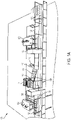
Figures 1A and1B , asystem 100 for manufacturing plywood having an automated core veneer feeder in accordance with an exemplary embodiment is shown. As illustrated, thesystem 100 includes amain conveyor 102 which extends through the entire manufacturing line. Thesystem 100 also includes aface sheet apparatus 104, disposed near a first end of themain conveyor 102, which is configured to placeface sheets 106 onto themain conveyor 102. After theface sheets 106 are placed onto themain conveyor 102, theface sheets 106 are then moved through aglue application station 108 where an adhesive is applied to an upper surface of theface sheets 106. - In exemplary embodiments, the
system 100 includes an automatedcore veneer feeder 110 which feeds pieces ofcore veneer 111 onto aveneer conveyor 112. In one embodiment not according to the invention, theveneer conveyor 112 moves the pieces ofcore veneer 111 to an assembly station where anoperator 114 places the pieces ofcore veneer 111 on top of theface sheets 106. In another embodiment not according to the invention, theveneer conveyor 112 moves the pieces ofcore veneer 111 to and places the pieces ofcore veneer 111 on top of theface sheets 106; theoperator 114 then adjusts the alignment of the pieces ofcore veneer 111 as needed. In exemplary embodiments not according to the invention, theoperator 114 ensures that there are no gaps between the adjacent pieces ofcore veneer 111 and that the adjacent pieces ofcore veneer 111 do not overlap when positioned on theface sheet 106. - In exemplary embodiments, the
operator 114 may use acontroller 116 to control the operation of the automatedcore veneer feeder 110. In exemplary embodiments, thecontroller 116 is used to instruct the automatedcore veneer feeder 110 to feed additional pieces ofcore veneer 111 onto theveneer conveyor 112. In one embodiment, thecontroller 116 may be a remote that includes one or more buttons. In another embodiment, thecontroller 116 may be a pedal controller or an optical sensor that the operator can use with one of his hands or feet to signal that additional pieces ofcore veneer 111 need to be dispensed onto theveneer conveyor 112. - In exemplary embodiments, the operation of the automated
core veneer feeder 110 may be completely automated. In these embodiments, one ormore sensors 118 may be disposed along theveneer conveyor 112 and thesensors 118 can be used to determine the number of pieces ofcore veneer 111 on theveneer conveyor 112. The automatedcore veneer feeder 110 can be configured to monitor thesensors 118 and to automatically feed additional pieces ofcore veneer 111 onto theveneer conveyor 112 if thesensors 118 indicate that the number of pieces ofcore veneer 111 on theveneer conveyor 112 is below a threshold minimum amount. Alternatively, the automatedcore veneer feeder 110 can be configured to monitor thesensors 118 and to continuously feed additional pieces ofcore veneer 111 onto theveneer conveyor 112 until thesensors 118 indicate that the number of pieces ofcore veneer 111 on theveneer conveyor 112 has reached a desired amount. - Continuing with reference to
Figure 1 , after the pieces ofcore veneer 111 are properly positioned on theface sheet 106, themain conveyor 102 moves theface sheets 106 with the properly positioned pieces ofcore veneer 111 through a secondglue application station 108 and an adhesive is applied to an upper surface of pieces ofcore veneer 111. After the secondglue application station 108, themain conveyor 102 moves theface sheets 106 with the properly positioned pieces ofcore veneer 111 to aback sheet apparatus 120, which places aback sheet 122 on top of theface sheets 106 and the pieces ofcore veneer 111. Afterback sheet 122 is placed the loosely assembled plywood panel(s) are cut into 99" individual sheets, stacked and prepared for pressing.Figure 1 illustrates a three-ply panel construction; face, core veneer and back. Those of ordinary skill in the art will appreciate that the methods and systems disclosed herein can be used for panel constructions that are more than three-ply. - Referring now to
Figure 2 , an automated core veneer feeder 200 for manufacturing plywood in accordance with an exemplary embodiment is shown. The automated core veneer feeder 200 includes a pair of sweed rolls 202 that are configured to receive pieces ofcore veneer 212 and to feed the pieces ofcore veneer 212 onto a veneer conveyor. In exemplary embodiments, the pieces ofcore veneer 212 are stored in a stack 210 adjacent to the sweed rolls 202. The automated core veneer feeder 200 includes a vision system 208 that is configured to scan the top of the stack 210 ofcore veneers 212 and to be able to identify the size and placement of each of thecore veneers 212 on the top of the stack 210. In exemplary embodiments, the automated core veneer feeder 200 includes a vacuum feeder assembly 204 that is configured to lift individual pieces ofcore veneer 212 off of the stack 210 by turning on and off one or more vacuum cups 206. In exemplary embodiments, the vacuum feeder assembly 204 is capable of picking up multiple pieces ofcore veneer 212 from the top of the stack 210 at one time using the vacuum cups 206. Once the vacuum feeder assembly 204 lifts the pieces ofcore veneer 212 from the top of the stack 210, the vacuum feeder assembly 204 moves the pieces ofcore veneer 212 towards the sweed rolls 202. After the pieces ofcore veneer 212 make contact with the sweed rolls 202, the vacuum cups 206 will release the pieces ofcore veneer 212, allowing the pieces ofcore veneer 212 to be fed through the sweed rolls 202 and on to a veneer conveyor. - Referring now to
Figure 3 , a block diagram of an automatedcore veneer feeder 310 in accordance with an exemplary embodiment is shown. As illustrated, the automatedcore veneer feeder 310 includes aprocessor 312, avision system 314,sweed rolls 316 and avacuum feeder assembly 318. Theprocessor 312 may be a simple processor such as an ASIC or FPGA or it may be a traditional microprocessor. In exemplary embodiments, theprocessor 312 may receive input signals from one ormore sensors 302, acontroller 304 and/or thevision system 314 and responsively control the operation of thevacuum feeder assembly 318 and/or the sweed rolls 316. - In exemplary embodiments, the
processor 312 receives a signal from either thecontroller 304 or the one ormore sensors 302 which indicates that additional pieces of core veneer need to be placed on the veneer conveyor. In response to receiving such a signal, theprocessor 312 uses thevision system 314 to identify individual pieces of core veneer located on the core veneer stack. Once the individual pieces of core veneer have been identified, theprocessor 312 instructs thevacuum feeder assembly 318 to lift the identified individual pieces of core veneer with one or more vacuum cups 320. After the pieces of core veneer have been lifted, theprocessor 312 instructs thevacuum feeder assembly 318 to move the individual pieces of core veneer to contact the sweed rolls 316. In exemplary embodiments, theprocessor 312 may also control the operation of the sweed rolls 316 including when the sweed rolls 316 will be active and the speed of the sweed rolls 316. - Referring now to
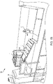
Figure 4 , asystem 400 for manufacturing plywood having an automated core veneer feeder and an automated core veneer layer in accordance with an exemplary embodiment is shown. Thesystem 400 is largely the same as thesystem 100 shown inFigures 1A and1B and the portions of thesystem 400 that are the same will not be discussed in further detail. In thesystem 400, theoperator 114 ofFigures 1A and1B , has been replaced with an automatedcore veneer layer 420. - In exemplary embodiments, the automated
core veneer layer 420 includes aveneer conveyor 422 that is capable of individually moving pieces ofcore veneer 411 in multiple directions. Theveneer conveyor 422 is also capable of placing the pieces ofcore veneer 411 onto theface sheet 406. In addition, the automatedcore veneer layer 420 includes a plurality ofsensors 424 that are configured to detect the pieces ofcore veneer 411 on theveneer conveyor 422. In exemplary embodiments, thesensor 424 may be optical sensors, weight sensors, or the like. The automatedcore veneer layer 420 further includes a processor configured to receive signals from thesensors 424 and to responsively calculate both the position and size of each of the pieces ofcore veneer 411 on theveneer conveyor 422. Once the position and size of the pieces ofcore veneer 411 on theveneer conveyor 422 is known, the processor instructs theveneer conveyor 422 to move the pieces ofcore veneer 411 to properly align the pieces ofcore veneer 411. In exemplary embodiments, the proper alignment of the pieces of core veneer 411ensures that there are no gaps between the adjacent pieces ofcore veneer 411 and that the adjacent pieces of core veneer 411do not overlap. In addition, the proper alignment may ensure that at least one edge of all of the pieces ofcore veneer 411 are aligned in a straight line. Once each piece ofcore veneer 411 is properly aligned by theveneer conveyor 422, theveneer conveyor 422 places each piece ofcore veneer 411 on top of an upper surface of aface sheet 406. - In one embodiment, the
veneer conveyor 422 is configured to place the pieces ofcore veneer 411 on top of an upper surface of aface sheet 406 in a continuous manner such that there are no gaps between the pieces ofcore veneer 411 and such that gaps between adjacent piece offace sheets 406 are covered by the pieces ofcore veneer 411. In another embodiment, theveneer conveyor 422 is configured to place the pieces ofcore veneer 411 on top of an upper surface of aface sheet 406 in a manner such that the gaps between adjacent piece offace sheets 406 are not completely covered by the pieces ofcore veneer 411. -
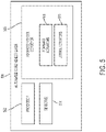
Figure 5 is a block diagram illustrating an automatedcore veneer layer 500 in accordance with an exemplary embodiment. In exemplary embodiments, the automatedcore veneer layer 500 includes aprocessor 502, one ormore sensors 504 and aveneer conveyor 506. Theprocessor 502 may be a simple processor such as an ASIC or FPGA or it may be a traditional microprocessor. Theprocessor 502 receives input signals from the one ormore sensors 504 and responsively calculates both the position and size of the pieces of core veneer on theveneer conveyor 506. In exemplary embodiments, the one ormore sensors 504 are disposed along theveneer conveyor 506 and may include, but are not limited to, optical sensors, weight sensors, and the like. Based on the calculated size and position of the of the pieces of core veneer on theveneer conveyor 506, theprocessor 502 uses one or more of aforward actuators 508 andlateral actuators 510 to individually move each of the pieces of core veneer on theveneer conveyor 506 into a desired position. Theforward actuators 508 are used to move an individual piece of core veneer up and down theveneer conveyor 506 and the lateral actuators can be used to move an individual piece of core from side to side on theveneer conveyor 506. - In exemplary embodiments, a system for manufacturing plywood having an automated core veneer feeder and an automated core veneer layer can substantially reduce the labor costs associated with manufacturing plywood. In addition, such systems may also increase the speed and efficiency of the plywood manufacturing process, quality and raw materials utilization. In exemplary embodiments, an automated core veneer feeder may be used to replace an operator that is currently used to feed individual pieces of core veneer onto a veneer conveyor. Likewise, an automated core veneer layer may be used to replace an operator that is currently used to remove individual pieces of core veneer from the veneer conveyor and place the individual pieces of core veneer on a face sheet.
- The terminology used herein is for the purpose of describing particular embodiments only and is not intended to be limiting of the invention. As used herein, the singular forms "a", "an" and "the" are intended to include the plural forms as well, unless the context clearly indicates otherwise. It will be further understood that the terms "comprises" and/or "comprising," when used in this specification, specify the presence of stated features, integers, steps, operations, elements, and/or components, but do not preclude the presence or addition of one more other features, integers, steps, operations, element components, and/or groups thereof.
- While the preferred embodiment to the invention had been described, it will be understood that those skilled in the art, both now and in the future, may make various improvements and enhancements which fall within the scope of the claims which follow.
Claims (6)
- A method for manufacturing plywood, comprising:receiving a face sheet (406) on a main conveyor (102); andfeeding a plurality of pieces of core veneer (411) onto a veneer conveyor (422, 506) by an automated core veneer feeder (310);characterized in that the method further comprises:detecting each of the plurality of pieces of core veneer (411) on the veneer conveyor (422, 506) by one or more sensors (424, 504);calculating, by a processor (502) based on data received from the one or more sensors (424, 504), a position and a size of each of the plurality of pieces of core veneer (411) on the veneer conveyor (422, 506);aligning the plurality of pieces of core veneer (411) by one or more forward actuators (508), wherein the one or more forward actuators (508) are directed by the processor (502) to individually move the each of the plurality of pieces of core veneer (411) up and down the veneer conveyor (422, 506), wherein the aligning ensures that there are no gaps between adjacent pieces of core veneer (411) and that the adjacent pieces of core veneer (411) do not overlap,removing, by an automated core veneer layer (420, 500), the plurality of pieces of core veneer (411) from the veneer conveyor (422, 506) after the plurality of pieces of core veneer (411) have been properly aligned; andplacing, by the automated core veneer layer (420, 500), the plurality of pieces of core veneer (411) onto the face sheet.
- The method of claim 1, wherein the automated core veneer feeder (310) feeds additional pieces of core veneer (411) onto the veneer conveyor (422, 506) based on a determination that a number of pieces of core veneer (411) on the veneer conveyor (422, 506) is below a desired threshold.
- The method of claim 1, wherein the automated core veneer feeder (310) continuously feeds pieces of core veneer (411) onto the veneer conveyor (422, 506) until a determination is made that a number of pieces of core veneer (411) on the veneer conveyor (422, 506) exceeds a maximum threshold.
- An automated core veneer layer (420, 500), comprising:a veneer conveyor (422, 506) having one or more sensors (424, 504) configured to detect a plurality of pieces of core veneer (411) on the veneer conveyor (422, 506);characterized by a processor (502) that is configured to receive input signals from the one or more sensors (424, 504) and responsively calculates a position and a size of each of the plurality of pieces of core veneer (411) on the veneer conveyor (422, 506);one or more actuators (508, 510) that individually move each of the plurality of pieces of core veneer (411) on the veneer conveyor (422, 506) into a desired position, wherein the one or more actuators include one or more forward actuators (508) controlled by the processor (502) to:wherein the veneer conveyor (422, 506) is configured to place the plurality of pieces of core veneer (411) onto a face sheet (406) after the plurality of pieces of core veneer (411) have been properly aligned.
individually move the each of the plurality of pieces of core veneer (411) up and down the veneer conveyor (422, 506) to ensure that there are no gaps between adjacent pieces of core veneer (411) and that the adjacent pieces of core veneer (411) do not overlap; - The automated core veneer layer of claim 4, wherein the one or more sensors (424, 504) are disposed along the veneer conveyor (422, 506) and include one of an optical sensor, weight sensor and/or core veneer alignment table.
- The automated core veneer layer of claim 4, wherein the one or more actuators include a lateral actuator (510) that moves each of the plurality of pieces of core veneer (411) on the veneer conveyor (422, 506) from side to side on the veneer conveyor (422, 506).
Applications Claiming Priority (2)
| Application Number | Priority Date | Filing Date | Title |
|---|---|---|---|
| US201462047143P | 2014-09-08 | 2014-09-08 | |
| PCT/US2015/048789 WO2016040227A1 (en) | 2014-09-08 | 2015-09-08 | Automated core veneer feeder and layer for manufacturing plywood |
Publications (3)
| Publication Number | Publication Date |
|---|---|
| EP3191274A1 EP3191274A1 (en) | 2017-07-19 |
| EP3191274A4 EP3191274A4 (en) | 2018-01-31 |
| EP3191274B1 true EP3191274B1 (en) | 2022-05-04 |
Family
ID=55436687
Family Applications (1)
| Application Number | Title | Priority Date | Filing Date |
|---|---|---|---|
| EP15839910.5A Active EP3191274B1 (en) | 2014-09-08 | 2015-09-08 | Method for manufacturing plywood and automated core veneer layer |
Country Status (3)
| Country | Link |
|---|---|
| US (2) | US10076849B2 (en) |
| EP (1) | EP3191274B1 (en) |
| WO (1) | WO2016040227A1 (en) |
Families Citing this family (14)
| Publication number | Priority date | Publication date | Assignee | Title |
|---|---|---|---|---|
| WO2016040227A1 (en) * | 2014-09-08 | 2016-03-17 | Georgia-Pacific Wood Products Llc | Automated core veneer feeder and layer for manufacturing plywood |
| DE102016203578A1 (en) * | 2016-03-04 | 2017-09-07 | Homag Gmbh | Device with suction device |
| IT201700034071A1 (en) * | 2017-03-28 | 2018-09-28 | Angelo Cremona S P A | APPARATUS FOR THE CONSTRUCTION OF PLYWOOD PANELS IN WOOD. |
| US11222419B1 (en) | 2017-12-06 | 2022-01-11 | Boise Cascade Company | Method and system for veneer grading and stacking using vision system analysis |
| US11200663B1 (en) * | 2017-12-06 | 2021-12-14 | Boise Cascade Company | Method and system for layered wood product production using local robotic panel assembly cells and vision system analysis |
| US20200173914A1 (en) | 2018-11-30 | 2020-06-04 | Boise Cascade Company | Method and system for detecting moisture levels in wood products using near infrared imaging |
| TWI696055B (en) * | 2019-03-27 | 2020-06-11 | 三泰科技股份有限公司 | The checking system and the method of the material and smt |
| CN110480763B (en) * | 2019-07-31 | 2021-05-14 | 嘉兴宝龙新材料股份有限公司 | Bonding and laminating equipment for plywood production and processing |
| CN111267461B (en) * | 2020-03-12 | 2021-11-12 | 上海汇俞实业发展有限公司 | Fireproof plate manufacturing, processing and treating process |
| ES2954776T3 (en) * | 2020-04-24 | 2023-11-24 | Flooring Technologies Ltd | Device and procedure for depositing wood veneers |
| US11279121B2 (en) * | 2020-05-19 | 2022-03-22 | RfsProtech, LLC | Apparatus and method for fabricating laminated wood products |
| US11186990B1 (en) | 2020-07-23 | 2021-11-30 | Boise Cascade Company | LVL structure |
| US20220161454A1 (en) * | 2020-11-20 | 2022-05-26 | Boise Cascade Company | Method and system for layered wood product production |
| US11453211B2 (en) | 2020-11-20 | 2022-09-27 | Boise Cascade Company | Method and system for layered wood product production |
Family Cites Families (17)
| Publication number | Priority date | Publication date | Assignee | Title |
|---|---|---|---|---|
| US3620887A (en) | 1968-06-04 | 1971-11-16 | Victor R Nelson | Method and apparatus for assembling veneer plies into laid-up plywood panels |
| US3580778A (en) * | 1968-06-27 | 1971-05-25 | Jeddeloh Bros Sweed Mills Inc | Method and apparatus for plywood panel lay-up |
| US3598252A (en) * | 1969-04-01 | 1971-08-10 | Fmc Corp | Apparatus for assembling veneer into plywood sheets |
| US3533518A (en) * | 1969-04-09 | 1970-10-13 | Potlatch Forests Inc | Vacuum feeder for plywood veneer core sheets |
| US3666592A (en) * | 1969-04-09 | 1972-05-30 | Potlatch Forests Inc | Method for automatically laying up plywood panels |
| US3725183A (en) * | 1971-03-29 | 1973-04-03 | Weyerhaeuser Co | Automatic plywood layup machine |
| US4797169A (en) * | 1986-07-02 | 1989-01-10 | Hashimoto Denki Co. Ltd. | Method and apparatus for assembling veneer sheet into a plywood |
| US5695596A (en) * | 1996-05-07 | 1997-12-09 | Seguin; Jacques | Apparatus for laying up veneer panels |
| DE19627024B4 (en) * | 1996-07-04 | 2007-08-02 | Dieffenbacher Gmbh + Co. Kg | Method and plant for the continuous folding and gluing of veneer sheets to veneer layer boards |
| US6085813A (en) * | 1998-10-30 | 2000-07-11 | Georgia-Pacific Corporation | Method for making plywood |
| DE19916041A1 (en) * | 1999-04-09 | 2000-10-12 | Dieffenbacher Gmbh Maschf | Production machine for veneer panels comprises suction conveyor belts, double belt conveyors, cutter, sewing machine and feeder belt |
| US6543604B1 (en) * | 2001-03-24 | 2003-04-08 | Columbia Forest Products, Inc. | Blank for plywood |
| DE10392231T5 (en) * | 2002-01-23 | 2005-03-10 | Raute Wood Ltd., New Westminster | Method and device for veneering |
| FI20070654A0 (en) * | 2007-08-29 | 2007-08-29 | Raute Oyj | Hardware for moving plate-like objects |
| FI121873B (en) * | 2009-09-09 | 2011-05-31 | Raute Oyj | Procedure for optimal parking of veneer sheets at the laying station |
| FI125692B (en) * | 2011-06-15 | 2016-01-15 | Raute Oyj | Apparatus for receiving and positioning veneer-fed veneers at a desired location |
| WO2016040227A1 (en) * | 2014-09-08 | 2016-03-17 | Georgia-Pacific Wood Products Llc | Automated core veneer feeder and layer for manufacturing plywood |
-
2015
- 2015-09-08 WO PCT/US2015/048789 patent/WO2016040227A1/en active Application Filing
- 2015-09-08 US US14/847,102 patent/US10076849B2/en active Active
- 2015-09-08 EP EP15839910.5A patent/EP3191274B1/en active Active
-
2018
- 2018-09-07 US US16/124,284 patent/US10513048B2/en active Active
Also Published As
| Publication number | Publication date |
|---|---|
| EP3191274A1 (en) | 2017-07-19 |
| WO2016040227A1 (en) | 2016-03-17 |
| US10076849B2 (en) | 2018-09-18 |
| US20190001519A1 (en) | 2019-01-03 |
| EP3191274A4 (en) | 2018-01-31 |
| US10513048B2 (en) | 2019-12-24 |
| US20160067879A1 (en) | 2016-03-10 |
Similar Documents
| Publication | Publication Date | Title |
|---|---|---|
| EP3191274B1 (en) | Method for manufacturing plywood and automated core veneer layer | |
| US20230144765A1 (en) | Conveyor device for conveying food products | |
| EP3325386B1 (en) | Apparatus to overturn sheets and/or panels | |
| CA2831757C (en) | Bacon card feeding system | |
| US10011444B2 (en) | Bacon card feeding system | |
| US9309077B2 (en) | Apparatus for receiving and positioning veneers fed in a position with camera | |
| DK175297B1 (en) | Method and machine for dispensing palletizing sheets | |
| US20180079646A1 (en) | Sheet manufacturing device and manufacturing method | |
| CA2992132A1 (en) | Method for unstacking veneer sheets | |
| CN102431827A (en) | Method for centering veneer sheets in a pile | |
| US6386812B2 (en) | Cover-feeder | |
| EP3685934B1 (en) | Workpiece conveying system, conveyed workpiece number detector, and control method for the workpiece conveying system | |
| EP3257794B1 (en) | Glass processing table with separate loading and processing areas | |
| JP5685018B2 (en) | Single plate insertion / adsorption feeder | |
| KR101403474B1 (en) | Trimming device of a strip | |
| JP2015217494A (en) | Sheet bundle cutting device | |
| EP2176044B1 (en) | Apparatus for forming stacks of panels to be fed to a user station | |
| JP5703465B2 (en) | Bookbinding equipment | |
| JP4703914B2 (en) | Sheet alignment device | |
| CN102234034B (en) | Cover feeder | |
| EP1300352A2 (en) | Method and device for picking up superimposed sheets of glass | |
| JPS6225482B2 (en) | ||
| JP6681299B2 (en) | Sheet-shaped food stacking device | |
| CN109607287A (en) | Recumbent is without hurting catcher | |
| WO2013057195A3 (en) | Apparatus for feeding sheet material |
Legal Events
| Date | Code | Title | Description |
|---|---|---|---|
| STAA | Information on the status of an ep patent application or granted ep patent |
Free format text: STATUS: THE INTERNATIONAL PUBLICATION HAS BEEN MADE |
|
| PUAI | Public reference made under article 153(3) epc to a published international application that has entered the european phase |
Free format text: ORIGINAL CODE: 0009012 |
|
| STAA | Information on the status of an ep patent application or granted ep patent |
Free format text: STATUS: REQUEST FOR EXAMINATION WAS MADE |
|
| 17P | Request for examination filed |
Effective date: 20170308 |
|
| AK | Designated contracting states |
Kind code of ref document: A1 Designated state(s): AL AT BE BG CH CY CZ DE DK EE ES FI FR GB GR HR HU IE IS IT LI LT LU LV MC MK MT NL NO PL PT RO RS SE SI SK SM TR |
|
| AX | Request for extension of the european patent |
Extension state: BA ME |
|
| DAV | Request for validation of the european patent (deleted) | ||
| DAX | Request for extension of the european patent (deleted) | ||
| REG | Reference to a national code |
Ref country code: DE Ref legal event code: R079 Ref document number: 602015078763 Country of ref document: DE Free format text: PREVIOUS MAIN CLASS: B27D0001000000 Ipc: B27D0001040000 |
|
| A4 | Supplementary search report drawn up and despatched |
Effective date: 20180105 |
|
| RIC1 | Information provided on ipc code assigned before grant |
Ipc: B65G 43/00 20060101ALI20171222BHEP Ipc: B65G 43/08 20060101ALI20171222BHEP Ipc: B65H 3/08 20060101ALI20171222BHEP Ipc: B65G 47/91 20060101ALI20171222BHEP Ipc: B27D 1/00 20060101ALI20171222BHEP Ipc: B27D 1/04 20060101AFI20171222BHEP |
|
| STAA | Information on the status of an ep patent application or granted ep patent |
Free format text: STATUS: EXAMINATION IS IN PROGRESS |
|
| 17Q | First examination report despatched |
Effective date: 20190718 |
|
| STAA | Information on the status of an ep patent application or granted ep patent |
Free format text: STATUS: EXAMINATION IS IN PROGRESS |
|
| GRAP | Despatch of communication of intention to grant a patent |
Free format text: ORIGINAL CODE: EPIDOSNIGR1 |
|
| STAA | Information on the status of an ep patent application or granted ep patent |
Free format text: STATUS: GRANT OF PATENT IS INTENDED |
|
| INTG | Intention to grant announced |
Effective date: 20211129 |
|
| GRAS | Grant fee paid |
Free format text: ORIGINAL CODE: EPIDOSNIGR3 |
|
| GRAA | (expected) grant |
Free format text: ORIGINAL CODE: 0009210 |
|
| STAA | Information on the status of an ep patent application or granted ep patent |
Free format text: STATUS: THE PATENT HAS BEEN GRANTED |
|
| AK | Designated contracting states |
Kind code of ref document: B1 Designated state(s): AL AT BE BG CH CY CZ DE DK EE ES FI FR GB GR HR HU IE IS IT LI LT LU LV MC MK MT NL NO PL PT RO RS SE SI SK SM TR |
|
| REG | Reference to a national code |
Ref country code: GB Ref legal event code: FG4D |
|
| REG | Reference to a national code |
Ref country code: CH Ref legal event code: EP |
|
| REG | Reference to a national code |
Ref country code: AT Ref legal event code: REF Ref document number: 1488542 Country of ref document: AT Kind code of ref document: T Effective date: 20220515 |
|
| REG | Reference to a national code |
Ref country code: DE Ref legal event code: R096 Ref document number: 602015078763 Country of ref document: DE |
|
| REG | Reference to a national code |
Ref country code: IE Ref legal event code: FG4D |
|
| REG | Reference to a national code |
Ref country code: FI Ref legal event code: FGE |
|
| REG | Reference to a national code |
Ref country code: LT Ref legal event code: MG9D |
|
| REG | Reference to a national code |
Ref country code: NL Ref legal event code: MP Effective date: 20220504 |
|
| PG25 | Lapsed in a contracting state [announced via postgrant information from national office to epo] |
Ref country code: SE Free format text: LAPSE BECAUSE OF FAILURE TO SUBMIT A TRANSLATION OF THE DESCRIPTION OR TO PAY THE FEE WITHIN THE PRESCRIBED TIME-LIMIT Effective date: 20220504 Ref country code: PT Free format text: LAPSE BECAUSE OF FAILURE TO SUBMIT A TRANSLATION OF THE DESCRIPTION OR TO PAY THE FEE WITHIN THE PRESCRIBED TIME-LIMIT Effective date: 20220905 Ref country code: NO Free format text: LAPSE BECAUSE OF FAILURE TO SUBMIT A TRANSLATION OF THE DESCRIPTION OR TO PAY THE FEE WITHIN THE PRESCRIBED TIME-LIMIT Effective date: 20220804 Ref country code: NL Free format text: LAPSE BECAUSE OF FAILURE TO SUBMIT A TRANSLATION OF THE DESCRIPTION OR TO PAY THE FEE WITHIN THE PRESCRIBED TIME-LIMIT Effective date: 20220504 Ref country code: LT Free format text: LAPSE BECAUSE OF FAILURE TO SUBMIT A TRANSLATION OF THE DESCRIPTION OR TO PAY THE FEE WITHIN THE PRESCRIBED TIME-LIMIT Effective date: 20220504 Ref country code: HR Free format text: LAPSE BECAUSE OF FAILURE TO SUBMIT A TRANSLATION OF THE DESCRIPTION OR TO PAY THE FEE WITHIN THE PRESCRIBED TIME-LIMIT Effective date: 20220504 Ref country code: GR Free format text: LAPSE BECAUSE OF FAILURE TO SUBMIT A TRANSLATION OF THE DESCRIPTION OR TO PAY THE FEE WITHIN THE PRESCRIBED TIME-LIMIT Effective date: 20220805 Ref country code: ES Free format text: LAPSE BECAUSE OF FAILURE TO SUBMIT A TRANSLATION OF THE DESCRIPTION OR TO PAY THE FEE WITHIN THE PRESCRIBED TIME-LIMIT Effective date: 20220504 Ref country code: BG Free format text: LAPSE BECAUSE OF FAILURE TO SUBMIT A TRANSLATION OF THE DESCRIPTION OR TO PAY THE FEE WITHIN THE PRESCRIBED TIME-LIMIT Effective date: 20220804 |
|
| PG25 | Lapsed in a contracting state [announced via postgrant information from national office to epo] |
Ref country code: RS Free format text: LAPSE BECAUSE OF FAILURE TO SUBMIT A TRANSLATION OF THE DESCRIPTION OR TO PAY THE FEE WITHIN THE PRESCRIBED TIME-LIMIT Effective date: 20220504 Ref country code: PL Free format text: LAPSE BECAUSE OF FAILURE TO SUBMIT A TRANSLATION OF THE DESCRIPTION OR TO PAY THE FEE WITHIN THE PRESCRIBED TIME-LIMIT Effective date: 20220504 Ref country code: LV Free format text: LAPSE BECAUSE OF FAILURE TO SUBMIT A TRANSLATION OF THE DESCRIPTION OR TO PAY THE FEE WITHIN THE PRESCRIBED TIME-LIMIT Effective date: 20220504 Ref country code: IS Free format text: LAPSE BECAUSE OF FAILURE TO SUBMIT A TRANSLATION OF THE DESCRIPTION OR TO PAY THE FEE WITHIN THE PRESCRIBED TIME-LIMIT Effective date: 20220904 |
|
| PG25 | Lapsed in a contracting state [announced via postgrant information from national office to epo] |
Ref country code: SM Free format text: LAPSE BECAUSE OF FAILURE TO SUBMIT A TRANSLATION OF THE DESCRIPTION OR TO PAY THE FEE WITHIN THE PRESCRIBED TIME-LIMIT Effective date: 20220504 Ref country code: SK Free format text: LAPSE BECAUSE OF FAILURE TO SUBMIT A TRANSLATION OF THE DESCRIPTION OR TO PAY THE FEE WITHIN THE PRESCRIBED TIME-LIMIT Effective date: 20220504 Ref country code: RO Free format text: LAPSE BECAUSE OF FAILURE TO SUBMIT A TRANSLATION OF THE DESCRIPTION OR TO PAY THE FEE WITHIN THE PRESCRIBED TIME-LIMIT Effective date: 20220504 Ref country code: EE Free format text: LAPSE BECAUSE OF FAILURE TO SUBMIT A TRANSLATION OF THE DESCRIPTION OR TO PAY THE FEE WITHIN THE PRESCRIBED TIME-LIMIT Effective date: 20220504 Ref country code: DK Free format text: LAPSE BECAUSE OF FAILURE TO SUBMIT A TRANSLATION OF THE DESCRIPTION OR TO PAY THE FEE WITHIN THE PRESCRIBED TIME-LIMIT Effective date: 20220504 Ref country code: CZ Free format text: LAPSE BECAUSE OF FAILURE TO SUBMIT A TRANSLATION OF THE DESCRIPTION OR TO PAY THE FEE WITHIN THE PRESCRIBED TIME-LIMIT Effective date: 20220504 |
|
| REG | Reference to a national code |
Ref country code: DE Ref legal event code: R097 Ref document number: 602015078763 Country of ref document: DE |
|
| PLBE | No opposition filed within time limit |
Free format text: ORIGINAL CODE: 0009261 |
|
| STAA | Information on the status of an ep patent application or granted ep patent |
Free format text: STATUS: NO OPPOSITION FILED WITHIN TIME LIMIT |
|
| PG25 | Lapsed in a contracting state [announced via postgrant information from national office to epo] |
Ref country code: AL Free format text: LAPSE BECAUSE OF FAILURE TO SUBMIT A TRANSLATION OF THE DESCRIPTION OR TO PAY THE FEE WITHIN THE PRESCRIBED TIME-LIMIT Effective date: 20220504 |
|
| 26N | No opposition filed |
Effective date: 20230207 |
|
| PG25 | Lapsed in a contracting state [announced via postgrant information from national office to epo] |
Ref country code: MC Free format text: LAPSE BECAUSE OF FAILURE TO SUBMIT A TRANSLATION OF THE DESCRIPTION OR TO PAY THE FEE WITHIN THE PRESCRIBED TIME-LIMIT Effective date: 20220504 |
|
| REG | Reference to a national code |
Ref country code: CH Ref legal event code: PL |
|
| GBPC | Gb: european patent ceased through non-payment of renewal fee |
Effective date: 20220908 |
|
| REG | Reference to a national code |
Ref country code: BE Ref legal event code: MM Effective date: 20220930 |
|
| PG25 | Lapsed in a contracting state [announced via postgrant information from national office to epo] |
Ref country code: SI Free format text: LAPSE BECAUSE OF FAILURE TO SUBMIT A TRANSLATION OF THE DESCRIPTION OR TO PAY THE FEE WITHIN THE PRESCRIBED TIME-LIMIT Effective date: 20220504 |
|
| PG25 | Lapsed in a contracting state [announced via postgrant information from national office to epo] |
Ref country code: LU Free format text: LAPSE BECAUSE OF NON-PAYMENT OF DUE FEES Effective date: 20220908 |
|
| P01 | Opt-out of the competence of the unified patent court (upc) registered |
Effective date: 20230528 |
|
| PG25 | Lapsed in a contracting state [announced via postgrant information from national office to epo] |
Ref country code: LI Free format text: LAPSE BECAUSE OF NON-PAYMENT OF DUE FEES Effective date: 20220930 Ref country code: IE Free format text: LAPSE BECAUSE OF NON-PAYMENT OF DUE FEES Effective date: 20220908 Ref country code: CH Free format text: LAPSE BECAUSE OF NON-PAYMENT OF DUE FEES Effective date: 20220930 |
|
| REG | Reference to a national code |
Ref country code: AT Ref legal event code: UEP Ref document number: 1488542 Country of ref document: AT Kind code of ref document: T Effective date: 20220504 |
|
| PG25 | Lapsed in a contracting state [announced via postgrant information from national office to epo] |
Ref country code: BE Free format text: LAPSE BECAUSE OF NON-PAYMENT OF DUE FEES Effective date: 20220930 |
|
| PG25 | Lapsed in a contracting state [announced via postgrant information from national office to epo] |
Ref country code: GB Free format text: LAPSE BECAUSE OF NON-PAYMENT OF DUE FEES Effective date: 20220908 |
|
| PGFP | Annual fee paid to national office [announced via postgrant information from national office to epo] |
Ref country code: IT Payment date: 20230810 Year of fee payment: 9 Ref country code: FI Payment date: 20230912 Year of fee payment: 9 Ref country code: AT Payment date: 20230825 Year of fee payment: 9 |
|
| PGFP | Annual fee paid to national office [announced via postgrant information from national office to epo] |
Ref country code: FR Payment date: 20230703 Year of fee payment: 9 Ref country code: DE Payment date: 20230712 Year of fee payment: 9 |
|
| PG25 | Lapsed in a contracting state [announced via postgrant information from national office to epo] |
Ref country code: HU Free format text: LAPSE BECAUSE OF FAILURE TO SUBMIT A TRANSLATION OF THE DESCRIPTION OR TO PAY THE FEE WITHIN THE PRESCRIBED TIME-LIMIT; INVALID AB INITIO Effective date: 20150908 |
|
| PG25 | Lapsed in a contracting state [announced via postgrant information from national office to epo] |
Ref country code: CY Free format text: LAPSE BECAUSE OF FAILURE TO SUBMIT A TRANSLATION OF THE DESCRIPTION OR TO PAY THE FEE WITHIN THE PRESCRIBED TIME-LIMIT Effective date: 20220504 |