EP3191032B1 - Apparatus for sensing position between layers of an eye - Google Patents
Apparatus for sensing position between layers of an eye Download PDFInfo
- Publication number
- EP3191032B1 EP3191032B1 EP15774752.8A EP15774752A EP3191032B1 EP 3191032 B1 EP3191032 B1 EP 3191032B1 EP 15774752 A EP15774752 A EP 15774752A EP 3191032 B1 EP3191032 B1 EP 3191032B1
- Authority
- EP
- European Patent Office
- Prior art keywords
- needle
- eye
- cannula
- operable
- choroid
- Prior art date
- Legal status (The legal status is an assumption and is not a legal conclusion. Google has not performed a legal analysis and makes no representation as to the accuracy of the status listed.)
- Active
Links
Images


Classifications
-
- A—HUMAN NECESSITIES
- A61—MEDICAL OR VETERINARY SCIENCE; HYGIENE
- A61F—FILTERS IMPLANTABLE INTO BLOOD VESSELS; PROSTHESES; DEVICES PROVIDING PATENCY TO, OR PREVENTING COLLAPSING OF, TUBULAR STRUCTURES OF THE BODY, e.g. STENTS; ORTHOPAEDIC, NURSING OR CONTRACEPTIVE DEVICES; FOMENTATION; TREATMENT OR PROTECTION OF EYES OR EARS; BANDAGES, DRESSINGS OR ABSORBENT PADS; FIRST-AID KITS
- A61F9/00—Methods or devices for treatment of the eyes; Devices for putting in contact-lenses; Devices to correct squinting; Apparatus to guide the blind; Protective devices for the eyes, carried on the body or in the hand
- A61F9/0008—Introducing ophthalmic products into the ocular cavity or retaining products therein
-
- A—HUMAN NECESSITIES
- A61—MEDICAL OR VETERINARY SCIENCE; HYGIENE
- A61B—DIAGNOSIS; SURGERY; IDENTIFICATION
- A61B17/00—Surgical instruments, devices or methods
- A61B17/02—Surgical instruments, devices or methods for holding wounds open, e.g. retractors; Tractors
- A61B17/0231—Surgical instruments, devices or methods for holding wounds open, e.g. retractors; Tractors for eye surgery
-
- A—HUMAN NECESSITIES
- A61—MEDICAL OR VETERINARY SCIENCE; HYGIENE
- A61B—DIAGNOSIS; SURGERY; IDENTIFICATION
- A61B17/00—Surgical instruments, devices or methods
- A61B17/34—Trocars; Puncturing needles
- A61B17/3417—Details of tips or shafts, e.g. grooves, expandable, bendable; Multiple coaxial sliding cannulas, e.g. for dilating
- A61B17/3421—Cannulas
-
- A—HUMAN NECESSITIES
- A61—MEDICAL OR VETERINARY SCIENCE; HYGIENE
- A61B—DIAGNOSIS; SURGERY; IDENTIFICATION
- A61B17/00—Surgical instruments, devices or methods
- A61B17/34—Trocars; Puncturing needles
- A61B17/3478—Endoscopic needles, e.g. for infusion
-
- A—HUMAN NECESSITIES
- A61—MEDICAL OR VETERINARY SCIENCE; HYGIENE
- A61B—DIAGNOSIS; SURGERY; IDENTIFICATION
- A61B3/00—Apparatus for testing the eyes; Instruments for examining the eyes
- A61B3/0016—Operational features thereof
- A61B3/0041—Operational features thereof characterised by display arrangements
-
- A—HUMAN NECESSITIES
- A61—MEDICAL OR VETERINARY SCIENCE; HYGIENE
- A61B—DIAGNOSIS; SURGERY; IDENTIFICATION
- A61B3/00—Apparatus for testing the eyes; Instruments for examining the eyes
- A61B3/10—Objective types, i.e. instruments for examining the eyes independent of the patients' perceptions or reactions
- A61B3/102—Objective types, i.e. instruments for examining the eyes independent of the patients' perceptions or reactions for optical coherence tomography [OCT]
-
- A—HUMAN NECESSITIES
- A61—MEDICAL OR VETERINARY SCIENCE; HYGIENE
- A61B—DIAGNOSIS; SURGERY; IDENTIFICATION
- A61B3/00—Apparatus for testing the eyes; Instruments for examining the eyes
- A61B3/10—Objective types, i.e. instruments for examining the eyes independent of the patients' perceptions or reactions
- A61B3/12—Objective types, i.e. instruments for examining the eyes independent of the patients' perceptions or reactions for looking at the eye fundus, e.g. ophthalmoscopes
-
- A—HUMAN NECESSITIES
- A61—MEDICAL OR VETERINARY SCIENCE; HYGIENE
- A61F—FILTERS IMPLANTABLE INTO BLOOD VESSELS; PROSTHESES; DEVICES PROVIDING PATENCY TO, OR PREVENTING COLLAPSING OF, TUBULAR STRUCTURES OF THE BODY, e.g. STENTS; ORTHOPAEDIC, NURSING OR CONTRACEPTIVE DEVICES; FOMENTATION; TREATMENT OR PROTECTION OF EYES OR EARS; BANDAGES, DRESSINGS OR ABSORBENT PADS; FIRST-AID KITS
- A61F9/00—Methods or devices for treatment of the eyes; Devices for putting in contact-lenses; Devices to correct squinting; Apparatus to guide the blind; Protective devices for the eyes, carried on the body or in the hand
- A61F9/0008—Introducing ophthalmic products into the ocular cavity or retaining products therein
- A61F9/0017—Introducing ophthalmic products into the ocular cavity or retaining products therein implantable in, or in contact with, the eye, e.g. ocular inserts
-
- A—HUMAN NECESSITIES
- A61—MEDICAL OR VETERINARY SCIENCE; HYGIENE
- A61F—FILTERS IMPLANTABLE INTO BLOOD VESSELS; PROSTHESES; DEVICES PROVIDING PATENCY TO, OR PREVENTING COLLAPSING OF, TUBULAR STRUCTURES OF THE BODY, e.g. STENTS; ORTHOPAEDIC, NURSING OR CONTRACEPTIVE DEVICES; FOMENTATION; TREATMENT OR PROTECTION OF EYES OR EARS; BANDAGES, DRESSINGS OR ABSORBENT PADS; FIRST-AID KITS
- A61F9/00—Methods or devices for treatment of the eyes; Devices for putting in contact-lenses; Devices to correct squinting; Apparatus to guide the blind; Protective devices for the eyes, carried on the body or in the hand
- A61F9/007—Methods or devices for eye surgery
- A61F9/00736—Instruments for removal of intra-ocular material or intra-ocular injection, e.g. cataract instruments
-
- A—HUMAN NECESSITIES
- A61—MEDICAL OR VETERINARY SCIENCE; HYGIENE
- A61B—DIAGNOSIS; SURGERY; IDENTIFICATION
- A61B90/00—Instruments, implements or accessories specially adapted for surgery or diagnosis and not covered by any of the groups A61B1/00 - A61B50/00, e.g. for luxation treatment or for protecting wound edges
- A61B90/36—Image-producing devices or illumination devices not otherwise provided for
- A61B90/361—Image-producing devices, e.g. surgical cameras
- A61B2090/3614—Image-producing devices, e.g. surgical cameras using optical fibre
-
- A—HUMAN NECESSITIES
- A61—MEDICAL OR VETERINARY SCIENCE; HYGIENE
- A61B—DIAGNOSIS; SURGERY; IDENTIFICATION
- A61B90/00—Instruments, implements or accessories specially adapted for surgery or diagnosis and not covered by any of the groups A61B1/00 - A61B50/00, e.g. for luxation treatment or for protecting wound edges
- A61B90/36—Image-producing devices or illumination devices not otherwise provided for
- A61B90/37—Surgical systems with images on a monitor during operation
- A61B2090/373—Surgical systems with images on a monitor during operation using light, e.g. by using optical scanners
- A61B2090/3735—Optical coherence tomography [OCT]
-
- A—HUMAN NECESSITIES
- A61—MEDICAL OR VETERINARY SCIENCE; HYGIENE
- A61B—DIAGNOSIS; SURGERY; IDENTIFICATION
- A61B90/00—Instruments, implements or accessories specially adapted for surgery or diagnosis and not covered by any of the groups A61B1/00 - A61B50/00, e.g. for luxation treatment or for protecting wound edges
- A61B90/20—Surgical microscopes characterised by non-optical aspects
-
- A—HUMAN NECESSITIES
- A61—MEDICAL OR VETERINARY SCIENCE; HYGIENE
- A61B—DIAGNOSIS; SURGERY; IDENTIFICATION
- A61B90/00—Instruments, implements or accessories specially adapted for surgery or diagnosis and not covered by any of the groups A61B1/00 - A61B50/00, e.g. for luxation treatment or for protecting wound edges
- A61B90/36—Image-producing devices or illumination devices not otherwise provided for
- A61B90/361—Image-producing devices, e.g. surgical cameras
-
- G—PHYSICS
- G02—OPTICS
- G02B—OPTICAL ELEMENTS, SYSTEMS OR APPARATUS
- G02B3/00—Simple or compound lenses
- G02B3/0087—Simple or compound lenses with index gradient
Definitions
- the human eye comprises several layers.
- the white outer layer is the sclera, which surrounds the choroid layer.
- the retina is interior to the choroid layer.
- the sclera contains collagen and elastic fiber, providing protection to the choroid and retina.
- the choroid layer includes vasculature providing oxygen and nourishment to the retina.
- the retina comprises light sensitive tissue, including rods and cones.
- the macula is located at the center of the retina at the back of the eye, generally centered on an axis passing through the centers of the lens and cornea of the eye (i.e., the optic axis). The macula provides central vision, particularly through cone cells.
- Macular degeneration is a medical condition that affects the macula, such that people suffering from macular degeneration may experience lost or degraded central vision while retaining some degree of peripheral vision.
- Macular degeneration may be caused by various factors such as age (also known as "AMD") and genetics.
- Age also known as "AMD”
- Macular degeneration may occur in a "dry” (nonexudative) form, where cellular debris known as drusen accumulates between the retina and the choroid, resulting in an area of geographic atrophy.
- Macular degeneration may also occur in a "wet" (exudative) form, where blood vessels grow up from the choroid behind the retina. Even though people having macular degeneration may retain some degree of peripheral vision, the loss of central vision may have a significant negative impact on the quality of life.
- the quality of the remaining peripheral vision may be degraded and in some cases may disappear as well. It may therefore be desirable to provide treatment for macular degeneration in order to prevent or reverse the loss of vision caused by macular degeneration. In some cases it may be desirable to provide such treatment in a highly localized fashion, such as by delivering a therapeutic substance in the subretinal layer (under the neurosensory layer of the retina and above the retinal pigment epithelium) directly adjacent to the area of geographic atrophy, near the macula. However, since the macula is at the back of the eye and underneath the delicate layer of the retina, it may be difficult to access the macula in a practical fashion.
- WO 2010/132751 discloses devices and methods for accessing the sub-retinal space that lies between the retina and the choroid in order to introduce therapies.
- the devices comprise a catheter and ancillary devices are provided to assist in placing catheters into the sub-retinal space.
- the catheter devices incorporate a lumen for delivery of therapeutic substances or devices into the eye.
- WO 2005/107845 discloses tools and related methods to surgically access the suprachoroidal space of an eye for the purpose of performing minimally invasive surgery or deliver drugs to the eye.
- a flexible microcannula device is provided that may be placed into the suprachoroidal space through a small incision of the overlying tissues, maneuvered to the appropriate region of the space and then activated to treat tissues adjacent to the distal tip of the device.
- WO 2007/087061 discloses methods and devices for implanting into the eye.
- a shunt is inserted through an incision in the cornea of the eye into the anterior chamber of the eye.
- the shunt includes a fluid passageway.
- the shunt is moved into the suprachoroidal space and positioned in a first position such that a first portion of the fluid passageway communicates with the anterior chamber and a second portion of the fluid passageway communicates with the suprachoroidal space to provide a fluid passageway between the suprachoroidal space and the anterior chamber.
- the invention provides a system for delivering a therapeutic agent to an eye according to claim 1.
- Preferred embodiments are defined in the dependent claims.
- proximal and distal are defined herein relative to a surgeon or other operator grasping a surgical instrument having a distal surgical end effector.
- proximal refers the position of an element closer to the surgeon or other operator and the term “distal” refers to the position of an element closer to the surgical end effector of the surgical instrument and further away from the surgeon or other operator.
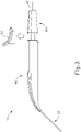
- FIGS. 1-4 show an exemplary instrument (10) that is configured for use in a procedure for the subretinal administration of a therapeutic agent to an eye of a patient from a suprachoroidal approach.
- Instrument (10) comprises a flexible cannula (20), a body (40), and a slidable (60).
- Cannula (20) extends distally from body (40) and has a generally rectangular cross section.
- Cannula (20) is generally configured to support a needle (30) that is slidable within cannula (20), as will be described in greater detail below.
- cannula (20) comprises a flexible material such as Polyether block amide (PEBA), which may be manufactured under the trade name PEBAX.
- PEBA Polyether block amide
- cannula (20) has a cross-sectional profile dimension of approximately 2.0 mm by 0.8 mm, with a length of approximately 80 mm. Alternatively, any other suitable dimensions may be used.
- cannula (20) is flexible enough to conform to specific structures and contours of the patient's eye, yet cannula (20) has sufficient column strength to permit advancement of cannula (20) between the sclera and choroid of patient's eye without buckling.
- the durometer of the material used to construct cannula (20) at least partially characterizes the flexibility of cannula (20).
- the material that is used to form cannula (20) may have a shore hardness of approximately 27D, approximately 33D, approximately 42D, approximately 46D, or any other suitable shore hardness.
- shore hardness may fall within the range of approximately 27D to approximately 46D; or more particularly within the range of approximately 33D to approximately 46D; or more particularly within the range of approximately 40D to approximately 45D.
- the particular cross-sectional shape of cannula (20) may also at least partially characterize the flexibility of cannula (20).
- the stiffness of needle (30) disposed within cannula (20) may at least partially characterize the flexibility of cannula (20).
- the flexibility of cannula (20) may be quantified by calculating a flexural stiffness for cannula (20). Flexural stiffness is calculated by the product of the elastic modulus and the area moment of inertia.
- one exemplary material that may be used to form cannula (20) may have a shore hardness of D27, an elastic modulus (E) of 1.2 ⁇ 10 7 N/m 2 , and an area moment of inertia (I x ) of 5.52 ⁇ 10 -14 m 4 , providing a calculated flexural stiffness about the x-axis at 0.7 ⁇ 10 -6 Nm 2 .
- cannula (20) may have a shore hardness of D33, an elastic modulus (E) of 2.1 ⁇ 10 7 N/m 2 , and an area moment of inertia (I x ) of 5.52 ⁇ 10 -14 m 4 , providing a calculated flexural stiffness about the x-axis at 1.2 ⁇ 10 -6 Nm 2 .
- cannula (20) may have a shore hardness of D42, an elastic modulus (E) of 7.7 ⁇ 10 7 N/m 2 , and an area moment of inertia (I x ) of 5.52 ⁇ 10 -14 m 4 , providing a calculated flexural stiffness about the x-axis at 4.3 ⁇ 10 -6 Nm 2 .
- cannula (20) may have a shore hardness of D46, an elastic modulus (E) of 17.0 ⁇ 10 7 N/m 2 , and an area moment of inertia (I x ) of 5.52 ⁇ 10 -14 m 4 , providing a calculated flexural stiffness about the x-axis at 9.4 ⁇ 10 -6 Nm 2 .
- the flexural stiffness of cannula (20) may fall within the range of approximately 0.7 ⁇ 10 -6 Nm 2 to approximately 9.4 ⁇ 10 -6 Nm 2 ; or more particularly within the range of approximately 1.2 ⁇ 10 -6 Nm 2 to approximately 9.4 ⁇ 10 -6 Nm 2 ; or more particularly within the range of approximately 2.0 ⁇ 10 -6 Nm 2 to approximately 7.5 ⁇ 10 -6 Nm 2 ; or more particularly within the range of approximately 2.0 ⁇ 10 -6 Nm 2 to approximately 6.0 ⁇ 10 -6 Nm 2 ; or more particularly within the range of approximately 3.0 ⁇ 10 -6 Nm 2 to approximately 5.0 ⁇ 10 -6 Nm 2 ; or more particularly within the range of approximately 4.0 ⁇ 10 -6 Nm 2 to approximately 5.0 ⁇ 10 -6 Nm 2 .
- the flexibility of cannula (20) may also be quantified by the following formula:
- flexural stiffness (EI) is calculated experimentally by deflecting cannula (20) having a fixed span (L) a set distance to yield a predetermined amount of deflection ( ⁇ ). The amount of force (F) required for such a deflection may then be recorded.
- cannula (20) may have a span of 0.06 m and may be deflected for a given distance.
- one exemplary material that may be used to form cannula (20) may require a force of 0.0188 N to achieve a deflection of 0.0155 m, providing a calculated flexural stiffness about the x-axis of 5.5 ⁇ 10 -6 Nm 2 .
- cannula (20) may require a force of 0.0205 N to achieve a deflection of 0.0135 m, providing a calculated flexural stiffness about the x-axis of 6.8 ⁇ 10 -6 Nm 2 .
- a force of 0.0199 N to achieve a deflection of 0.0099 m may be required to achieve a deflection of 9.1 ⁇ 10 -6 Nm 2 .
- cannula (20) may require a force of 0.0241 N to achieve a deflection of 0.0061 m, providing a calculated flexural stiffness about the x-axis of 1.8 ⁇ 10 -6 Nm 2 .
- a force of 0.0190 N to achieve a deflection 0.0081 m may be required to achieve a deflection 0.0081 m, providing a calculated flexural stiffness about the x-axis of 1.0 ⁇ 10 -6 Nm 2 .
- cannula (20) may require a force of 0.0215 N to achieve a deflection of 0.0114 m, providing a calculated flexural stiffness about the x-axis of 8.4 ⁇ 10 -6 Nm 2 .
- a force of 0.0193 N to achieve a deflection of 0.0170 m may be required to achieve a deflection of 0.0170 m, providing a calculated flexural stiffness about the x-axis of 5.1 ⁇ 10 -6 Nm 2 .
- cannula (20) may require a force of 0.0224 N to achieve a deflection of 0.0152 m, providing a calculated flexural stiffness about the x-axis of 6.6 ⁇ 10 -6 Nm 2 .
- a force of 0.0183 N to achieve a deflection of 0.0119 m may require a force of 0.0183 N to achieve a deflection of 0.0119 m, providing a calculated flexural stiffness about the x-axis of 6.9 ⁇ 10 -6 Nm 2 .
- cannula (20) may require a force of 0.0233 N to achieve a deflection of 0.0147 m, providing a calculated flexural stiffness about the x-axis of 7.1 ⁇ 10 -6 Nm 2 .
- a force of 0.0192 N to achieve a deflection of 0.0122 may be required to achieve a deflection of 0.0122, providing a calculated flexural stiffness about the x-axis of 7.1 ⁇ 10 -6 Nm 2 .
- cannula (20) may require a force of 0.0201 N to achieve a deflection of 0.0201, providing a calculated flexural stiffness about the x-axis of 4.5 ⁇ 10 -6 Nm 2 .
- the flexural stiffness of cannula (20) may fall within the range of approximately 1.0 ⁇ 10 -6 Nm 2 to approximately 9.1 ⁇ 10 -6 Nm 2 .
- the flexural stiffness of cannula may fall within the range of approximately 0.7 ⁇ 10 -6 Nm 2 to approximately 11.1 ⁇ 10 -6 Nm 2 ; or more particularly within the range of approximately 2.0 ⁇ 10 -6 Nm 2 to approximately 6.0 ⁇ 10 -6 Nm 2 .
- Needle (30) may have a flexural stiffness that differs from the flexural stiffness of cannula (20).
- needle (30) may be formed of a nitinol material that has an elastic modulus (E) of 7.9 ⁇ 10 10 N/m 2 , and an area moment of inertia (I x ) of 2.12 ⁇ 10 -17 m 4 , providing a calculated flexural stiffness about the x-axis at 1.7 ⁇ 10 -6 Nm 2 .
- the flexural stiffness of needle (30) may fall within the range of approximately 0.5 ⁇ 10 -6 Nm 2 to approximately 2.5 ⁇ 10 -6 Nm 2 ; or more particularly within the range of approximately 0.75 ⁇ 10 -6 Nm 2 to approximately 2.0 ⁇ 10 -6 Nm 2 ; or more particularly within the range of approximately 1.25 ⁇ 10 -6 Nm 2 to approximately 1.75 ⁇ 10 -6 Nm 2 .
- cannula (20) comprises two side lumens (22) and a single central lumen (24) extending longitudinally through cannula (20) and terminating at an atraumatic, beveled distal end (26).
- a beveled lateral opening (28) is located proximal to beveled distal end (26).
- Side lumens (22) contribute to the flexibility of cannula (20).
- lumens (22, 24) are shown as being open at beveled distal end (26), it should be understood that in some examples, side lumens (22, 24) may be optionally closed at beveled distal end (26).
- central lumen (24) is configured to receive needle (30) and a needle guide (80).
- an optical fiber (not shown) is also disposed in central lumen (24) alongside needle (30). Such an optical fiber may be used to provide illumination and/or optical feedback as will be described in greater detail below.
- Beveled distal end (26) is generally beveled to provide separation between the sclera and choroid layers to enable cannula (20) to be advanced between such layers while not inflicting trauma to the sclera or choroid layers.
- beveled distal end (26) is beveled at an angle of approximately 15° relative to the longitudinal axis of cannula (20) in the present example.
- beveled distal end (26) may have a bevel angle within the range of approximately 5° to approximately 50°; or more particularly within the range of approximately 5° to approximately 40°; or more particularly within the range of approximately 10° to approximately 30°; or more particularly within the range of approximately 10° to approximately 20°.
- a needle guide (80) is disposed within lumen (24) such that the distal end of needle guide (80) abuts beveled lateral opening (28). Needle guide (80) is generally configured to direct needle (30) upwardly along an exit axis (EA) that is obliquely oriented relative to the longitudinal axis (LA) of cannula (20) through beveled opening (28) of cannula (20). Needle guide (80) may be formed of plastic, stainless steel, and/or any other suitable biocompatible material(s). The shape of needle guide (80) is configured for insertion into central lumen (24). In the present example, needle guide (80) is secured within central lumen (24) by a press or interference fit, although in other examples, adhesives and/or mechanical locking mechanisms may be used to secure needle guide (80).
- needle guide (80) defines an internal lumen (84) that is configured to slidably receive needle (30).
- internal lumen (84) includes a generally straight proximal portion (86) and a curved distal portion (88).
- Straight proximal portion (86) corresponds to the longitudinal axis (LA) of cannula (20), while curved distal portion (88) curves upwardly away from the longitudinal axis of cannula (20).
- Curved distal portion (88) of the present example is curved to direct needle (30) along an exit axis (EA) that extends distally from cannula (20) at an angle of approximately 7° to approximately 9° relative to the longitudinal axis (LA) of cannula (20). It should be understood that such an angle may be desirable to deflect needle (30) in a direction to ensure penetration of needle into the choroid (306) and to minimize the possibility of needle (30) continuing beneath the choroid (306) through the suprachoroidal space (as opposed to penetrating through the choroid (306)) and the possibility of retinal perforation.
- curved distal portion (88) may urge needle (30) to exit cannula (20) along an exit axis (EA) that is oriented at an angle within the range of approximately 5° to approximately 30° relative to the longitudinal axis (LA) of cannula (20); or more particularly within the range of approximately 5° to approximately 20° relative to the longitudinal axis (LA) of cannula (20); or more particularly within the range of approximately 5° to approximately 10° relative to the longitudinal axis (LA) of cannula (20).
- EA exit axis
- Needle (30) is in the form of an inner cannula that has a sharp distal end (32) and defines an internal lumen (34).
- Distal end (32) of the present example has a lancet configuration.
- distal end (32) has a tri-bevel configuration or any other configuration as described in US 2015-223977, entitled “Method and Apparatus for Suprachoroidal Administration of Therapeutic Agent," filed February 11, 2015 .
- Still other suitable forms that distal end (32) may take will be apparent to those of ordinary skill in the art in view of the teachings herein.
- Needle (30) of the present example comprises a stainless steel hypodermic needle that is sized to deliver the therapeutic agent while being small enough to minimize incidental trauma as needle (30) penetrates tissue structures of the patient's eye, as will be described in greater detail below. While stainless steel is used in the present example, it should be understood that any other suitable material(s) may be used, including but not limited to nitinol, etc.
- needle (30) may be 35 gauge with a 100 ⁇ m inner diameter, although other suitable sizes may be used.
- the outer diameter of needle (30) may fall within the range of 27 gauge to 45 gauge; or more particularly within the range of 30 gauge to 42 gauge; or more particularly within the range of 32 gauge to 39 gauge.
- the inner diameter of needle (30) may fall within the range of approximately 50 ⁇ m to approximately 200 ⁇ m; or more particularly within the range of approximately 50 ⁇ m to approximately 150 ⁇ m; or more particularly within the range of approximately 75 ⁇ m to approximately 125 ⁇ m.
- body (40) is generally shaped as an elongate rectangle with a curved distal end.
- the particular shape of body (40) that is shown is configured to be grasped by an operator.
- body (40) may be mounted on a support device or robotic arm for ease of positioning instrument (10), as described in US 2015-223977, entitled “Method and Apparatus for Suprachoroidal Administration of Therapeutic Agent,” filed February 11, 2015 .
- Actuation assembly (60) includes an actuation member (62) and a locking member (66).
- Locking member (66) is removably attachable to body engagement portion (50), between body (40) and actuation member (62).
- locking member (66) fills a space between body (40) and actuation member (62) to prevent actuation member (62) from being advanced distally relative to body (40).
- locking member (66) can be removed to selectively permit actuation member (62) to be advanced distally relative to body (40).
- FIGS. 2-4 show an exemplary actuation of instrument (10).
- needle (30) is initially retracted into cannula (20) and locking member (66) is positioned between body (40) and actuation member (62), thereby preventing advancement of actuation member (62).
- cannula (20) may be positioned within an eye of a patient as will be described in greater detail below.
- an operator may desire to advance needle (30) relative to cannula (20).
- an operator may first remove locking member (66) by pulling locking member (66) away from instrument (10), as can be seen in FIG. 3 .
- actuation member (62) may be moved or translated relative to body (40) to advance needle (30) relative to cannula (20) as described in U.S. Pat. App. No. 14/619,256, entitled “Method and Apparatus for Suprachoroidal Administration of Therapeutic Agent," filed February 11, 2015 .
- Actuation member (62) of the present example is only configured to translate needle (30) and not rotate needle (30). In other examples, it may be desirable to rotate needle (30). Accordingly, alternative examples may include features in actuation member (62) to rotate and translate needle (30).
- advancement of actuation member (62) into contact with body (40) as shown in FIG. 4 corresponds to advancement of needle (30) to a position relative to cannula (20) to a predetermined amount of penetration within an eye of a patient.
- instrument (10) is configured such that an operator only has to advance actuation member (62) into contact with body (40) to properly position needle (30) within an eye of a patient.
- the predetermined amount of advancement of needle (30) relative to cannula (20) is between approximately 0.25 mm to approximately 10 mm; or more particularly within the range of approximately 0.1 mm to approximately 10 mm; or more particularly within the range of approximately 2 mm to approximately 6 mm; or more particularly to approximately 4 mm.
- contact between actuation member (62) and body (40) may have no particular significance besides the maximum advancement of needle (30) relative to cannula (20).
- instrument (10) may be equipped with certain tactile feedback features to indicate to an operator when needle (30) has been advanced to certain predetermined distances relative to cannula (20). Accordingly, an operator may determine the desired depth of penetration of needle (30) into a patient's eye based on direct visualization of indicia on instrument and/or based on tactile feedback from instrument (10).
- tactile feedback features may be combined with the present example, as will be apparent to those of ordinary skill in the art in view of the teachings herein.
- instruments described herein it may be desirable to vary certain components or features of the instruments described herein. For instance, it may be desirable to utilize instruments similar to instrument (10) with alternative mechanisms to actuate needle (30). Yet in other examples, it may be desirable to utilize instruments similar to instrument (10) equipped with different cannula (20) or needle (30) geometries. Instruments having the above referenced variations may be desirable for different surgical procedures, or surgical procedures similar to the procedure discussed above, to engage tissue structures having varying physical properties. While certain examples of variations are described herein, it should be understood that the instruments described herein may include any other alternative features as will be apparent to those of ordinary skill in the art in view of the teachings herein.
- FIG. 7 shows an exemplary alternative instrument (2010) that is similar to instrument (10) described above. While certain features and operabilities of instrument (2010) are described below, it should be understood that, in addition to or in lieu of the following, instrument (2010) may be configured and/or operable in accordance with any of the teachings of US 2015-223977, entitled “Method and Apparatus for Suprachoroidal Administration of Therapeutic Agent," filed February 11, 2015 . Like with instrument (10), instrument (2010) of the present example is generally usable in the procedure described herein to deliver a therapeutic fluid subretinally to an eye of a patient from a suprachoroidal approach. It should therefore be understood that instrument (2010) may be readily used in place of instrument (10) to perform the medical procedures described herein.
- instrument (2010) of this example comprises a cannula (2020), a body (2040), and an actuation assembly (2100).
- Cannula (2020) includes a nitinol needle (2030) (shown in FIGS. 20-21 , 23B , 26B-26C , and 27B ) extending therethrough and is substantially the same as cannula (20) described above.
- cannula (2020) and needle (2030) are substantially identical to cannula (20) and needle (30) described above.
- instrument (10) The primary difference between instrument (10) and instrument (2010) is that actuation assembly (2100) of instrument (2010) is rotatable instead of being slidable. Additionally, instrument (2010) includes a valve assembly (not shown) that is operable to change the fluid state of needle (2030). Actuation assembly (2100) is generally operable to translate the valve assembly longitudinally to thereby translate needle (2030) longitudinally relative to cannula (2020) through rotation of a knob member (2110).
- knob member (2110) When actuation assembly (2100) is in the proximal position, an operator may rotate knob member (2110) in either a counter clockwise or clockwise direction. If knob member (2110) is rotated in the counter clockwise direction, rotation member (2110) will merely rotate freely. To begin advancement of actuation assembly (2100), the valve assembly, and needle (2030), an operator may rotate knob member (2110) in the clockwise direction. Clockwise rotation of knob member (2110) will act to translate knob member (2110) distally and will also act to translate the valve assembly and needle (2030) distally.
- An operator may continue clockwise rotation of knob member (2110) to drive needle (2030) out of the distal end of cannula (2020), such that a distal end (2032) of needle (2030) is distal to the distal end of cannula (2020).
- needle (2030) has been advanced to its furthest distal position relative to the distal end of cannula (2020)
- further clockwise rotation of knob member (2110) will merely result in free rotation of knob member (2110) due to slipping of clutch features that are integrated into actuation assembly (2100).
- the operator may actuate valve assembly to enable the delivery of therapeutic agent via a lumen (2034) of needle (2030) as described in greater detail below.
- actuation assembly (2100) is rotated to actuate the valve assembly, and needle (2030), the valve assembly and needle (2030) remain substantially rotationally stationary relative to body (2040).
- rotation member (2110) of the present example is described as being manually rotated, rotation member (2110) may be rotated via a motor and/or some other motive source.
- translation of needle (2030) may be mechanically/electrically driven via a servomotor.
- a servomotor may be controlled by a servo controller as will be described in more detail below.
- a servo control may be manually operated.
- a servo controller may be operated via a computer acting on feedback from instrument (2010) or any other component described herein.
- FIG. 8 shows an exemplary suture measurement template (210) that may be used in a procedure providing subretinal delivery of a therapeutic agent from a suprachoroidal approach, as will be described in greater detail below.
- template (210) is configured to be pressed against an eye of a patient to stamp a particular pattern of pigment onto the patient's eye. It should be understood that reference herein to pressing template (210) against an eye of a patent may include, but is not necessarily limited to, pressing template (210) directly against the sclera (304) surface (e.g., after the conjunctiva has been taken down or otherwise displaced).
- Template (210) comprises a rigid body (220) and a rigid shaft (240).
- body (220) is generally contoured to correspond to the curvature of a patient's eye such that body (220) may be pressed or placed onto at least a portion of the patient's eye.
- Body (220) comprises an upper guide portion (222) and a plurality of protrusions (230) extending distally from an eye face (224) of body (220).
- Upper guide portion (222) is generally semi-circular in shape and is disposed at the top of body (220).
- the semi-circular shape of upper guide portion (222) has a radius that corresponds to the curvature of the limbus of a patient's eye.
- upper guide portion (222) curves proximally along a first radius corresponding to a radius of curvature of a patient's eyeball; and downwardly (toward the longitudinal axis of shaft (240)) along a second radius corresponding to a radius of curvature of the limbus of the patient's eye.
- upper guide portion (222) may be used to properly locate template (210) relative to the limbus of the patient's eye. Accordingly, any pigmentation that may be deposited onto a patient's eye by template may be positioned relative to the limbus of the patient's eye.
- Protrusions (230) are spaced a predetermined distance from upper guide portion (222).
- protrusions (230) form a pattern that may correspond to relevant marks for use during the method described below.
- Protrusions (230) of the present example comprise four suture loop protrusions (230a-230h) and two sclerotomy protrusions (230i, 230j).
- Suture loop protrusions (230a-320h) and sclerotomy protrusions (230i, 230j) extend outwardly from body (220) an equal distance such that protrusions (230) collectively maintain the curvature defined by body (220).
- the tips of protrusions (230a-230j) all lie along a curved plane that is defined by a radius of curvature complementing the radius of curvature of the patient's eyeball.
- the tips of protrusions (230a-230j) are rounded and atraumatic such that protrusions (230a-230j) may be pressed against the eye without damaging the sclera or other portions of the patient's eye.
- Shaft (240) extends proximally from body (220). Shaft (240) is configured to permit an operator to grasp template (210) and manipulate body (220). In the present example, shaft (240) is integral with body (220). In other examples, shaft (240) may be selectively attachable to body by a mechanical fastening means such as a threaded coupling or a mechanical snap fit, etc. In some versions, an operator may be presented with a kit comprising a shaft (240) and a plurality of bodies (220). The bodies (220) may have different curvatures to correspond with different eyeballs having different radii of curvature.
- the operator may thus select an appropriate body (220) from the kit based on the anatomy of the particular patient before the operator; and the operator may then secure the selected body (220) to the shaft (240).
- the proximal end of shaft (240) may additionally include a t-grip, knob, or other gripping feature to permit an operator to more readily grip shaft (240).
- suture loop protrusions (232) and sclerotomy protrusions (234) each correspond to a particular portion of the method described below.
- an operator may coat protrusions (230) with a biocompatible pigment or ink by pressing protrusions (230) onto a pigment or ink pad (250), by brushing the pigment or ink onto protrusions (230), or by otherwise applying the pigment or ink to protrusions (230).
- protrusions (230) Once protrusions (230) have received the pigment or ink, an operator may mark an eye of a patent by pressing protrusions (230) of template (210) onto the eye of the patient, as will be described in greater detail below. Once template (210) is removed from an eye of a patient, the pigment from protrusions may remain adhered to the eye to mark particular points of interest, as will be described in greater detail below.
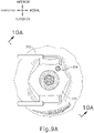
- FIGS. 9A-11C show an exemplary procedure for subretinal delivery of therapeutic agent from a suprachoroidal approach using instrument (10) described above. It should be understood however, that instrument (2010) may be readily used in addition to or in lieu of instrument (10) in the procedure described below.
- instrument (2010) may be readily used in addition to or in lieu of instrument (10) in the procedure described below.
- the method described herein may be employed to treat macular degeneration and/or other ocular conditions.
- the procedure described herein is discussed in the context of the treatment of age-related macular degeneration, it should be understood that no such limitation is intended or implied. For instance, in some merely exemplary alternative procedures, the same techniques described herein may be used to treat retinitis pigmentosa, diabetic retinopathy, and/or other ocular conditions. Additionally, it should be understood that the procedure described herein may be used to treat either dry or wet age-related macular degeneration.
- the procedure begins by an operator immobilizing tissue surrounding a patient's eye (301) (e.g., the eyelids) using a speculum (312), and/or any other instrument suitable for immobilization. While is immobilization described herein with reference to tissue surrounding eye (301), it should be understood that eye (301) itself may remain free to move.
- an eye chandelier port (314) is inserted into eye (301) to provide intraocular illumination when the interior of eye (301) is viewed through the pupil.
- eye chandelier port (314) is positioned in the inferior medial quadrant such that a superior temporal quadrant sclerotomy may be preformed. As can be seen in FIG.
- eye chandelier port (314) is positioned to direct light onto the interior of eye (314) to illuminate at least a portion of the retina (e.g., including at least a portion of the macula). As will be understood, such illumination corresponds to an area of eye (301) that is being targeted for delivery of therapeutic agent.
- only chandelier port (314) is inserted at this stage, without yet inserting an optical fiber (315) into port (314).
- an optical fiber (315) may be inserted into chandelier port (314) at this stage.
- a microscope may optionally be utilized to visually inspect the eye to confirm proper positioning of eye chandelier port (314) relative to the target site.
- FIG 9A shows a particular positioning of eye chandelier port (314), it should be understood that eye chandelier port (314) may have any other positioning as will be apparent to those of ordinary skill in the art in view of the teachings herein.
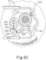
- the sclera (304) may be accessed by dissecting the conjunctiva by incising a flap in the conjunctiva and pulling the flap posteriorly. After such a dissection is completed, the exposed surface (305) of the sclera (304) may optionally be blanched using a cautery tool to minimize bleeding. Once conjunctiva dissection is complete, the exposed surface (305) of the sclera (304) may optionally be dried using a WECK-CEL or other suitable absorbent device. Template (210), described above, may then be used to mark eye (301). As can be seen in FIG. 9B , template (210) is positioned to align with the limbus of eye (301).
- Visual guide (320) comprises a set of suture loop markers (321, 322, 323, 324, 325, 326, 327) and a pair of sclerotomy markers (329).
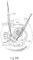
- FIG. 9D shows a completed suture loop assembly (330).
- suture loop assembly (330) is generally configured to guide cannula (20) of instrument (10) through a sclerotomy and into eye (301).
- An exemplary procedure that may be employed to create the suture loop assembly (330) that is shown in FIG. 9D is described in US 2015-223977, entitled “Method and Apparatus for Suprachoroidal Administration of Therapeutic Agent," filed February 11, 2015 .
- a sclerotomy may be performed on eye (301). As seen in FIG.
- eye (301) is cut between sclerotomy markers (329) using a conventional scalpel (313) or other suitable cutting instrument.
- sclerotomy markers (329) are shown as comprising two discrete dots, it should be understood that in other examples, markers (329) may comprise any other type of markings such as a solid, dotted or dashed line.
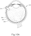
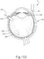
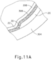
- the sclerotomy procedure forms a small incision (316) through sclera (304) of eye (301). As can best be seen in FIG. 10B , the sclerotomy is preformed with particular care to avoid penetration of the choroid (306). Thus, the sclerotomy procedure provides access to the space between sclera (304) and choroid (306).
- a blunt dissection may optionally be performed to locally separate sclera (304) from choroid (306). Such a dissection may be performed using a small blunt elongate instrument, as will be apparent to those of ordinary skill in the art in view of the teachings herein.
- cannula (20) of instrument (10) may insert cannula (20) of instrument (10) through incision (316) and into the space between sclera (304) and choroid (306).
- cannula (20) is directed through guide loops (336) of suture loop assembly (330) and into incision (316).
- guide loops (336) may stabilize cannula (20).
- guide loops (336) maintain cannula (20) in a generally tangential orientation relative to incision (316). Such tangential orientation may reduce trauma as cannula (20) is guided through incision (316) to stabilize cannula (20) and to prevent damage to surrounding tissue.
- cannula (20) may include one or more markers on the surface of cannula (20) to indicate various depths of insertion. While merely optional, such markers may be desirable to aid an operator in identifying the proper depth of insertion as cannula (20) is guided along an atraumatic path.
- the operator may visually observe the position of such markers in relation to guide loops (336) and/or in relation to incision (316) as an indication of the depth to which cannula (20) is inserted in eye (301).
- one such marker may correspond to an approximately 6 mm depth of insertion of cannula (20).
- cannula (20) is at least partially inserted into eye (301), an operator may insert an optical fiber (315) into eye chandelier port (314) the fiber (315) had not yet been inserted at this stage.
- eye chandelier port (314) With eye chandelier port (314) in place and assembled with optical fiber (315), an operator may activate eye chandelier port (314) by directing light through optical fiber (315) to provide illumination of eye (301) and thereby visualize the interior of eye (301). Further adjustments to the positioning of cannula (20) may optionally be made at this point to ensure proper positioning relative to the area of geographic atrophy of retina (308).
- the operator may wish to rotate the eye (301), such as by pulling on sutures (334, 339), to direct the pupil of the eye (301) toward the operator in order to optimize visualization of the interior of the eye (301) via the pupil.
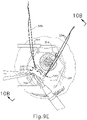
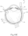
- FIGS. 9G and 10C-10D show cannula (20) as it is guided between sclera (304) and choroid (306) to the delivery site for the therapeutic agent.
- the delivery site corresponds to a generally posterior region of eye (301) adjacent to an area of geographic atrophy of retina (308).
- the delivery site of the present example is superior to the macula, in the potential space between the neurosensory retina and the retinal pigment epithelium layer.
- FIG. 9G shows eye (301) under direct visualization through a microscope directed through the pupil of eye (301), with illumination provided through fiber (315) and port (314).
- cannula (20) is at least partially visible through a retina (308) and choroid (306) of eye (301).
- an operator may track cannula (20) as it is advanced through eye (301) from the position shown in FIG. 10C to the position shown in 10D. Such tracking may be enhanced in versions where an optical fiber (34) is used to emit visible light through the distal end of cannula (20).
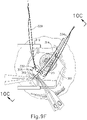
- needle (30) of instrument (10) may advance needle (30) of instrument (10) as described above with respect to FIGS. 3-4 .
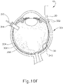
- needle (30) is advanced relative to cannula (20) such that needle (30) pierces through choroid (306) without penetrating retina (308).
- needle (30) may appear under direct visualization as "tenting" the surface of choroid (306), as can be seen in FIG. 9H .
- needle (30) may deform choroid (306) by pushing upwardly on choroid, providing an appearance similar to a tent pole deforming the roof of a tent.
- a visual phenomenon may be used by an operator to identify whether choroid (306) is about to be pierced and the location of any eventual piercing.
- the particular amount of needle (30) advancement sufficient to initiate "tenting" and subsequent piercing of choroid (306) may be of any suitable amount as may be determined by a number of factors such as, but not limited to, general patient anatomy, local patient anatomy, operator preference, and/or other factors.
- a merely exemplary range of needle (30) advancement may be between approximately 0.25 mm and approximately 10 mm; or more particularly between approximately 2 mm and approximately 6 mm.
- leading bleb (340) may be desirable for two reasons. First, as shown in FIGS. 91 , 10F , and 11B , leading bleb (340) may provide a further visual indicator to an operator to indicate when needle (30) is properly positioned at the delivery site.
- leading bleb (340) may provide a barrier between needle (30) and retina (308) once needle (30) has penetrated choroid (306). Such a barrier may push the retinal wall outwardly (as is best seen in FIGS. 10F and 11B ), thereby minimizing the risk of retinal perforation as needle (30) is advanced to the delivery site.
- a foot pedal is actuated in order to drive leading bleb (340) out from needle (30).
- other suitable features that may be used to drive leading bleb (340) out from needle (30) will be apparent to those of ordinary skill in the art in view of the teachings herein.
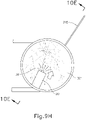
- a therapeutic agent (341) may be infused by actuating a syringe or other fluid delivery device as described above with respect to instrument (10).
- the particular therapeutic agent (341) delivered may be any suitable therapeutic agent configured to treat an ocular condition.
- suitable therapeutic agents may include, but are not necessarily limited to, drugs having smaller or large molecules, therapeutic cell solutions, certain gene therapy solutions, and/or any other suitable therapeutic agent as will be apparent to those of ordinary skill in the art in view of the teachings herein.
- the therapeutic agent (341) may be provided in accordance with at least some of the teachings of U.S. Patent No. 7,413,734, entitled “Treatment of Retinitis Pigmentosa with Human Umbilical Cord Cells,” issued August 19, 2008 .
- the amount of therapeutic agent (341) that is ultimately delivered to the delivery site is approximately 50 ⁇ L, although any other suitable amount may be delivered.
- a foot pedal is actuated in order to drive agent (341) out from needle (30).
- other suitable features that may be used to drive agent (341) out from needle (30) will be apparent to those of ordinary skill in the art in view of the teachings herein. Delivery of therapeutic agent may be visualized by an expansion of the pocket of fluid as can be seen in FIGS. 9J , 10G , and 11C . As shown, therapeutic agent (341) essentially mixes with the fluid of leading bleb (340) as therapeutic agent (341) is injected into the surprachoroidal space.
- needle (20) may be retracted by sliding actuation assembly (60) proximally relative to body (40); and cannula (30) may then be withdrawn from eye (301). It should be understood that because of the size of needle (20), the site where needle (20) penetrated through choroid (306) is self sealing, such that no further steps need be taken to seal the delivery site through choroid (306). Suture loop assembly (330) and chandelier (314) may be removed, and incision (316) in the sclera (304) may be closed using any suitable conventional techniques.
- the therapeutic agent (341) that is delivered by needle (20) may comprise cells that are derived from postpartum umbilicus and placenta.
- the therapeutic agent (341) may be provided in accordance with at least some of the teachings of U.S. Patent No. 7,413,734, entitled “Treatment of Retinitis Pigmentosa with Human Umbilical Cord Cells," issued August 19, 2008 .
- needle (20) may be used to deliver any other suitable substance or substances, in addition to or in lieu of those described in U.S. Patent No. 7,413,734 and/or elsewhere herein.
- therapeutic agent (341) may comprise various kinds of drugs including but not limited to small molecules, large molecules, cells, and/or gene therapies. It should also be understood that macular degeneration is just one merely illustrative example of a condition that may be treated through the procedure described herein. Other biological conditions that may be addressed using the instruments and procedures described herein will be apparent to those of ordinary skill in the art.
- instruments (10, 2010) may be desirable to provide instruments (10, 2010) with features that are operable to indicate when needles (30, 2030) have fully penetrated choroid (306) so as to minimize the risk of needles (30, 2030) perforating retina (308).
- instruments (10, 2010) may include sub-surface imaging technology that is operable to provide operators with images of tissue layers in the eye.
- instruments (10, 2010) may include light-emitting features that are operable to direct light through retina (308) after penetrating choroid (306).
- Instruments having the above referenced variations may be desirable for different surgical procedures, or surgical procedures similar to the procedure discussed above, to engage tissue structures having varying physical properties. While certain examples of variations are described herein, it should be understood that the instruments described herein may include any other alternative features as will be apparent to those of ordinary skill in the art in view of the teachings herein.
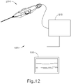
- FIGS. 12-24B show an exemplary surgical system (500) that is operable to perform the therapeutic agent delivery procedure described above.
- System (500) of the present example comprises instrument (2010), an interferometer system (510), and a display (520).
- system (500) will be described below as including instrument (2010), it should be appreciated that instrument (10) or other variations of instrument (2010) may be readily used in lieu of instrument (2010).
- system (500) of the present example includes display (520), it should be appreciated that display (520) is merely optional and instrument (2010) may be configured to provide visual and/or tactile feedback to an operator in addition to or in lieu of display (520).
- instrument (2010) may be configured to provide visual and/or tactile feedback to an operator once needle (2030) has penetrated choroid (306) but prior to perforating retina (308).
- interferometer system (510) is operable to obtain images of tissue layers within the eye.
- interferometer system (510) is operable to provide an operator with an optical coherence tomography (OCT) scan that depicts sub-surface layers of the eye.
- OCT optical coherence tomography
- Interferometer system (510) of the present example comprises a dispersive white-light interferometer (D-WLI), though it should be understood that any other suitable interferometer may be used as will be apparent to those of ordinary skill in the art in view of the teachings herein.
- FIG. 13 shows how interferometer system (510) is formed by several subsystems, each subsystem having its own set of components. In particular, FIG.
- interferometer system (510) of the present example comprises a power supply (530), a light source system (540), a position tracking system (550), a fiber optic assembly (560), a spectrometer (570), and an optical probe system (580). While interferometer system (510) is shown as being separate from yet coupled with instrument (2010), it should be understood that all or some of interferometer system (510) may be incorporated into instrument (2010). For instance, in some variations, power supply (530) is separate from yet coupled with instrument (2010); while the remainder of interferometer system (510) is incorporated directly into instrument (2010).
- Power supply (530) is operable to provide power to interferometer system (510). As shown in FIG. 14 , power supply (530) of the present example includes an AC/DC power supply (532) connected to an AC power network (534) (e.g., via a conventional cable and wall outlet). AC/DC power supply (532) is further connected to a connection and power distribution/adaptation board (536) via a power supply connector (538). An electrical cable (710) extends from power distribution/adaptation board (536) to light source system (540) as will be described in greater detail below. Power supply (530) further includes a data acquisition board (537) and a line sensor board (539) both of which are connectable with external devices via respective USB connectors (533, 535). Of course, power supply (530) may alternatively include any other suitable components or features in addition to or in lieu of those described above.
- light source system (540) of the present example includes a driver (542).
- Driver (542) is connected with connection and power distribution/adaptation board (536) of power supply (530) via cable (710), such that power supply (530) is operable to deliver electrical power to driver (542) via cable (710).
- Driver (542) is electrically coupled with light source system (540) such that driver (542) regulates the delivery of electrical power to light source (544).
- light source (544) is operable to generate light in the near-infrared (NIR) spectrum, though it should be understood that light source (544) may alternatively be configured to generate light elsewhere along the spectrum of light.
- Light source (544) is optically coupled with optical isolator (546) via an optical cable.
- Optical isolator (546) comprises a conventional optical isolator that is operable to provide one-way communication of light from light source (544), preventing light from being communicated back to light source (544).
- Optical isolator (544) is further coupled with fiber optic assembly (560) via an optical cable (720).
- light source system (540) may alternatively include any other suitable components or features in addition to or in lieu of those described above.
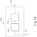
- Position tracking system (550) is also coupled with cable (710), such that position tracking system (550) also receives electrical power from power supply (530) via cable (710). As shown in FIG. 16 , position tracking system (550) also includes a driver (552). Driver (552) is connected with connection and power distribution/adaptation board (536) of power supply (530) via cable (710). Position tracking system (550) further includes a tracking light source (554) which is connected with driver (552) and is powered by driver (552). Tracking light source (554) is operable to generate light in the visible spectrum. It should be understood, however, that tracking light source (554) may alternatively be configured to generate light elsewhere along the spectrum of light. Tracking light source (554) is further coupled with fiber optic assembly (560) via an optical cable (730). Of course, position tracking system (550) may alternatively include any other suitable components or features in addition to or in lieu of those described above.
- fiber optic assembly (560) comprises a pair of optical connectors (561, 562).
- Optical connector (561) is connected to cable (720) from optical isolator (546) of light source system (540).
- Optical connector (562) is connected to cable (730) from tracking light source (554) of position tracking system (550).
- Optical connector (561) is further connected with an optical circulator (563).
- An optical output cable (740) is also coupled with optical circulator (563), leading to spectrometer (570) as will be described in greater detail below.
- Optical connector (562) and optical circulator (563) are connected to a fiber coupler (564).
- Fiber coupler (564) is further connected with a beam collimator (565) and an optical cable (750) that leads to optical probe system (580) as will be described in greater detail below.
- Beam collimator (565) is operable to project light toward an adjustable optical delay line (566).
- a portion of adjustable optical delay line (566) is manually movable toward and away from beam collimator (565) in order to selectively adjust delay.
- a delay line (556) adjustment is used to scan the interferometer path length in order to tune the signal.
- fiber optic assembly (560) has two optical lines - one that is used as reference, and another one to measure. The best quality or strength may be achieved when these two lines have the same (exact) optical length.
- fiber optic assembly (560) may alternatively include any other suitable components or features in addition to or in lieu of those described above.
- spectrometer (570) also includes a beam collimator (572) connected with cable (740) from circulator (563) of fiber optic assembly (560).
- Beam collimator (572) is operable to project light toward a grating (574) which in turn splits (or defracts) light toward a lens (576).
- Light passes through lens (576) toward an optical sensor (578).
- optical sensor (578) may comprise a CCD sensor, a CMOS sensor, and/or any other suitable kind of optical sensor.
- Optical sensor (578) is connected with line sensor board (539) of power supply (530) via an electrical cable (760), such that optical sensor (578) receives electrical power from power supply (530) via cable (760).
- Cable (760) is also configured to communicate data from optical sensor (578) to power supply (530), such that the data may be received and processed by data acquisition board (537) as described below.
- spectrometer (570) may alternatively include any other suitable components or features in addition to or in lieu of those described above.
- optical probe system (580) includes an optical connector (586) that is coupled with optical fiber (750) of fiber optic assembly (560).
- Optical connector (586) is further coupled with an optical probe (582) via an optical fiber (584).
- optical fiber (584) may comprise light guiding flexible fused silica capillary tubing, with a core of approximately 150 ⁇ m, a clad of approximately 165 ⁇ m, and a buffer of approximately 195 ⁇ m.
- optical fiber (584) may have any other suitable configuration.
- optical probe (582) is coupled with distal end (2032) of needle (2030) via an adhesive layer (583) such that optical probe (582) is configured to translate concurrently with needle (2030) within internal lumen (84) of needle guide (80) and further with needle (2030) as needle (2030) is directed out of cannula (20) along exit axis (EA) as needle (2030) penetrates the choroid (306).
- any suitable structures or techniques may be used to secure optical probe (582) with needle (2030), including but not limited to epoxies, clips, etc.
- Optical probe (582) of the present example is oriented substantially parallel with needle (2030) and is positioned adjacent an exterior side surface of needle (2030).
- optical probe (582) may be positioned adjacent the exterior surface of needle (2030) at any other appropriate position.
- optical probe (582) may be positioned adjacent an exterior top or bottom surface of needle (2030).
- optical probe (582) may be positioned in lumen (2034) of needle (2030), with the distal end of optical probe (582) being longitudinally positioned to coincide with the longitudinal position of distal end (2032) of needle (2030).
- the inner diameter of lumen (2034) is sufficiently larger than the outer diameter of optical probe (582) such that leading bleb (340) and therapeutic agent (341) may flow past optical probe (582) and out of distal end (2032), while optical probe (582) is positioned within lumen (2034).
- Lumen (2034) may thus be coupled with a fluidic-optical junction that enables the communication of both fluids (e.g., fluid for leading bleb (340) and therapeutic agent (341)) and optical probe (582) through lumen (2034).
- fluids e.g., fluid for leading bleb (340) and therapeutic agent (341)
- optical probe (582) is removed from lumen (2034) before leading bleb (340) and therapeutic agent (341) are communicated through lumen (2034).
- optical probe (582) is laterally offset from needle (2030) such that a gap exists between an exterior surface of optical probe (582) and the exterior surface of needle (2030) into which adhesive layer (583) may be positioned. Such a gap may be between 5-50 micrometers thick.
- optical probe (582) and needle (2030) may abut one another.
- optical probe (582) of the present example is positioned relative to needle (2030) such that a distal end of optical probe (582) is positioned proximally of the distal end of needle (2030).
- Optical probe (582) may, however, be positioned at any appropriate position along the length of needle (2030).
- optical probe (582) comprises a gradient-index (GRIN) lens (590), a ferrule (594), and a protective sleeve (596).
- Optical fiber (584) passes through ferrule (594) and projects an optical beam (592) through GRIN lens (590).
- Protective sleeve (596) is positioned about GRIN lens (590) and ferrule (594) to prevent damage to optical probe (582).
- optical probe (582) may be within the range of approximately 1.2 mm to 2.0 mm in length and approximately 250 ⁇ m in diameter.
- GRIN lens (590) may within the range of approximately 0.6 mm to 1.0 mm in length and approximately 250 ⁇ m in diameter.
- Ferrule (594) may within the range of approximately 0.6 mm to 1.0 mm in length and approximately 250 ⁇ m in diameter.
- adhesive layer (583) may be within the range of approximately 5 ⁇ m and 50 ⁇ m thick, thereby producing an effective diameter about optical probe (582) in the range of approximately 260 ⁇ m to 350 ⁇ m.
- any other suitable dimensions may be used for any of these components.
- some versions of optical probe (582) may have an effective diameter that is less than or equal to approximately 250 ⁇ m. Such smaller diameter may be preferred in versions where optical probe (582) is inserted into lumen (2034) of needle (2030).
- optical probe (582) may be used to project light from light sources (544, 554) and receive light that is backscattered and reflected from tissue layers that are in front of optical probe (582).
- the backscattered and reflected light may be collected by optical sensor (578) of spectrometer (570).
- the corresponding data from optical sensor (578) may then be communicated to data acquisition board (537).
- the different layers of the eye may provide different respective opacities. These different opacities may provide a series of corresponding spikes in a graph plotting the changes in luminance ( ⁇ L) of backscattered or reflected light along a line of sight of optical probe (582).
- Data acquisition board (537) may provide the data from optical sensor (578) to various components that process the data to render optical coherence tomography (OCT) images in real time via display (520) as described below.
- OCT optical coherence tomography
- Various suitable hardware components and software algorithms that may be used to convert data from interferometer system (510) into optical coherence tomography (OCT) images in real time via display (520) will be apparent to those of ordinary skill in the art in view of the teachings herein. It should also be understood that display (520) may be provided through a custom piece of capital equipment, a conventional video monitor, a conventional tablet, and/or any other suitable device.
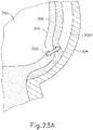
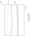
- needle (2030) and optical probe (582) are disposed within a distal end of cannula (2020) such that optical probe (582) projects optical beam (592) through choroid (306), retina (308), and into the vitreous region (310) of the eye to produce the image shown on display (520) as shown in FIG. 24A .
- optical probe (582) projects optical beam (592) through choroid (306), retina (308), and into the vitreous region (310) of the eye to produce the image shown on display (520) as shown in FIG. 24A .
- an operator can tell that choroid (306) has not been pierced as choroid (306) is still visible on display (520). In other words, choroid (306) is still distal to the distal end of needle (2030) and optical probe (582).
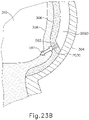
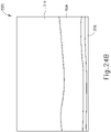
- needle (2030) and optical probe (582) are advanced relative to cannula (2020) such that needle (2030) and optical probe (582) pierce choroid (306) without penetrating retina (308). From this image, an operator can visually observe through display (520) that choroid (306) has been pierced because choroid (306) has nearly disappeared from display (520).
- optical probe (582) of the present example is positioned relative to needle (2030) such that a distal end of optical probe (582) is positioned proximally relative to the distal end of needle (2030).
- Interferometer system (510) may be configured to account for this offset of optical probe (582) relative to the distal end of needle (2030) so as to provide an accurate determination of when the distal end of needle (2030) has penetrated choroid (306) and reached the subretinal space just below choroid (306).
- instrument (2010) may be configured to provide an operator with visual, audible, and/or tactile feedback to alert the operator that choroid (306) has been pierced.
- a computer system may receive and process data from interferometer system (510).
- Such a computer system may exist as an external component relative to instrument (2010) or may be an internal component of instrument (2010).
- Such a computer system may be configured to alert a user in response to the occurrence of a change in luminance caused by penetration of choroid (306) thereby alerting the user that needle (2030) has reached the subretinal space just below choroid (306).
- Such an alert may be audible (e.g., a single beep or series of beeps), tactile (e.g., a slight vibration of instrument (2010)), or visual.
- instrument (2010) may include a single light or series of lights configured to illuminate or change color in response to a change in luminance as described above. Additionally, or alternatively, such lights may change color ( e.g., from green to red) or intensity ( e.g . from dim to bright) as needle (2030) penetrates choroid (306).
- optical probe (582) may be configured to illuminate or change color in response to a change in luminance as described above.
- optical probe (582) may change color (e.g., from green to red) or intensity (e.g. from dim to bright) as needle (2030) penetrates choroid (306).
- the operator may prefer to receive notification from instrument (2010) in audible and/or tactile/haptic form. This may enable the operator to maintain a view through a microscope or other instrument that is used to provide a view of the retina (308), etc., without requiring the operator to diver their view from the microscope or other viewing instrument in order to receive the notification from instrument (2010).
- interferometer system (510) and display (520) may be used in combination with instrument (2010) will be apparent to those of ordinary skill in the art in view of the teachings herein.
- FIGS. 25-27B show another exemplary surgical system (600) that may be used to perform the therapeutic agent delivery procedure described above.
- System (600) of the present example comprises instrument (2010), a microscope (610), a computer (620), a servo controller (630), a modulator (640), and a light source (650).
- instrument (2010) a microscope
- computer 620
- servo controller 630
- modulator 640
- a light source 650
- system (600) will be described below as including instrument (2010), it should be appreciated that instrument (10) or other variations of instrument (2010) may be readily used in lieu of instrument (2010).
- instrument (2010) is connected with light source (650) and servo controller (630).
- light source (650) comprises a fiber optic cable (652) that is coupled with needle (2030) such that fiber optic cable (652) is operable to translate concurrently with needle (2030).
- light source (650) is operable to project light from a distal end of needle (2030) into the eye via fiber optic cable (652).
- Light source (650) is operable to generate visible light (i.e ., with a wavelength between approximately 430 nm and 700 nm, or more specifically with a wavelength between approximately 500 nm and 600 nm), infrared light (i.e ., with a wavelength greater than approximately 700 nm), and/or near-infrared light.
- light source (650) provides light at a wavelength of approximately 635 nm.
- Light source (650) is connected with modulator (640) which is configured to modulate light provided by light source (650).
- light source (650) comprises a laser. Other suitable forms that light source (650) may take will be apparent to those of ordinary skill in the art in view of the teachings herein.
- Servo controller (630) is operable to control a servomotor (not shown). As discussed above, such a servomotor may be operable to drive translation of needle (2030) in addition to or in lieu of rotation member (2110). Various suitable components and features that may be used to provide actuation of needle (2030) under control of servo controller (630) will be apparent to those of ordinary skill in the art in view of the teachings herein. It should also be understood that needle (2030) may instead be driven manually (e.g., via a slider, via a screw advance, etc.), such that servo controller (630) and a servo motor may be omitted if desired.
- Servo controller (630) and modulator (640) are connected with computer (620), such that computer (620) is operable to execute control algorithms to drive both servo controller (630) and modulator (640).
- Computer (620) is connected with a camera (613) that is coupled with microscope (610).
- computer (620) is operable to control servo controller (630), the servo motor, modulator (640), and light source (650) based on feedback from camera (613).
- microscope (610) is operable to detect light from light source (650) shone through vitreous region (310) to thereby indicate when needle (2030) has fully penetrated choroid (306).
- microscope (610) is positioned adjacent the cornea (350) of the eye such that microscope (610) is operable to detect light projecting from vitreous region (310) and through the pupil (352) of the eye.
- This light projecting from vitreous region (310) and through the pupil (352) of the eye is configured to pass though an aspheric lens (604) so as to reduce or eliminate optical aberrations within the light.
- a light source (602) is configured to project visible light to provide illumination of the vitreous region (310) of the eye.
- the visible light from light source (602) passes through a beam splitter (606), which redirects the light to project through the pupil (352) into the vitreous region (310) of the eye.
- Beam splitter (606) further permits light that is projected back from the eye to pass through beam splitter (606) to reach microscope (610).
- Microscope (610) of the present example includes a series of lenses (611) that are operable to provide magnification.
- Microscope (610) further includes a dichroic beam splitter (612) that is operable to separate light.
- dichroic beam splitter (612) is operable to separate light in the visible spectrum (VIS) from light in the infrared spectrum (IR). Once separated, this VIS light is passes through one or more lenses (611) within microscope (610) and then through a filter (614) so as to enable visualization by the naked eye of a user at port (615); while the IR light passes into camera (613).
- Camera (613) includes one or more lenses (617) through which the IR light passes so as to focus the IR light from dichroic beam splitter (612).
- Image sensor (616) of the present example may be a charge-coupled device (CCD) image sensor, a complementary metal-oxide semiconductor (CMOS) image sensor, or any other appropriate type of image sensor.
- image sensor (616) is operably configured to capture images at a rate of 300 frames per second. This may provide a spatial resolution of approximately 1 ⁇ m when needle (2030) is advanced at a piercing speed of approximately 300 ⁇ m/s. Alternatively, any other suitable frame rate may be used for image sensor (616); and any other suitable piercing speed may be used for needle (2030).
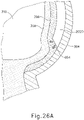
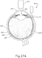
- cannula (2020) is positioned between sclera (304) and choroid (306).
- needle (2030) and fiber optic cable (652) are disposed within a distal end of cannula (2020) such that fiber optic cable (652) projects light (654) into choroid (306).
- light (654) from optic cable (652) does not pass through choroid (306) into retina (308) and vitreous region (310).
- light (654) from fiber optic cable (652) is either not visible or detectable via image sensor (616); or is partially detectable but faint.
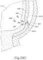
- needle (2030) and fiber optic cable (652) are advanced relative to cannula (2020) such that needle (2030) and fiber optic cable (652) partially pierce choroid (306).
- distal end (2032) of needle (2030) and fiber optic cable (652) are partially exposed relative to the distal end of cannula (2020) such that fiber optic cable (652) projects light (654) into choroid (306).
- light (654) from optic cable (652) does not pass completely through choroid (306) into retina (308) and vitreous region (310).
- needle (2030) and fiber optic cable (652) are further advanced relative to cannula (2020) such that needle (2030) and fiber optic cable (652) fully pierce choroid (306) without penetrating retina (308).
- fiber optic cable (652) projects light (654) into retina (308).
- light (654) from fiber optic cable (652) passes through retina (308) and into vitreous region (310).
- image sensor (616) at an intensity associated with distal end (2032) of needle (2030) and fiber optic cable (652) reaching the subretinal space above the choroid (306).
- image sensor (616) detects light (654) that exceeds the threshold intensity associated with distal end (2032) of needle (2030) and fiber optic cable (652) reaching the subretinal space above the choroid (306)
- computer (620) may stop the servomotor so as to prevent further translation of needle (2030) and fiber optic cable (652).
- instrument (2010) may provide an audible, tactile, and/or visual signal to the operator to indicate that the subretinal space has been reached.
- the operator may prefer to receive notification from instrument (2010) in audible and/or tactile/haptic form. This may enable the operator to maintain a view through a microscope or other instrument that is used to provide a view of the retina (308), etc., without requiring the operator to diver their view from the microscope or other viewing instrument in order to receive the notification from instrument (2010).
- needle (2030) is advanced manually instead of being advanced via servomotor, the operator may cease advancement of needle (2030) in response to the audible, tactile, and/or visual signal indicating that the subretinal space has been reached.
- the intensity of the light received by image sensor (616) increases.
- the highest jump in light intensity may occur once distal end (2032) of needle (2030) and fiber optic cable (652) pass from below the retinal pigment epithelium (RPE) to above the RPE.
- the light intensity may suddenly increase by approximately 20% to approximately 40% once distal end (2032) of needle (2030) and fiber optic cable (652) perforate the RPE.
- the intensity of the light received by image sensor (616) may also vary based on the position of distal end (2032) of needle (2030) and fiber optic cable (652) in the eye in accordance with the teachings of Gao, et al. "Measuring Retinal Contributions to the Optical Stiles-Crawford Effect with Optical Coherence Tomography.” OPTICS EXPRESS, 16.9 (2008): pp. 6486-6501 .
- Versions described above may be designed to be disposed of after a single use, or they can be designed to be used multiple times. Versions may, in either or both cases, be reconditioned for reuse after at least one use. Reconditioning may include any combination of the steps of disassembly of the device, followed by cleaning or replacement of particular pieces, and subsequent reassembly. In particular, some versions of the device may be disassembled, and any number of the particular pieces or parts of the device may be selectively replaced or removed in any combination. Upon cleaning and/or replacement of particular parts, some versions of the device may be reassembled for subsequent use either at a reconditioning facility, or by an operator immediately prior to a procedure. Those skilled in the art will appreciate that reconditioning of a device may utilize a variety of techniques for disassembly, cleaning/replacement, and reassembly.
- versions described herein may be sterilized before and/or after a procedure.
- the device is placed in a closed and sealed container, such as a plastic or TYVEK bag.
- the container and device may then be placed in a field of radiation that can penetrate the container, such as gamma radiation, x-rays, or high-energy electrons.
- the radiation may kill bacteria on the device and in the container.
- the sterilized device may then be stored in the sterile container for later use.
- a device may also be sterilized using any other technique known in the art, including but not limited to beta or gamma radiation, ethylene oxide, or steam.
Landscapes
- Health & Medical Sciences (AREA)
- Life Sciences & Earth Sciences (AREA)
- Biomedical Technology (AREA)
- Heart & Thoracic Surgery (AREA)
- Engineering & Computer Science (AREA)
- Animal Behavior & Ethology (AREA)
- General Health & Medical Sciences (AREA)
- Public Health (AREA)
- Veterinary Medicine (AREA)
- Surgery (AREA)
- Ophthalmology & Optometry (AREA)
- Medical Informatics (AREA)
- Molecular Biology (AREA)
- Nuclear Medicine, Radiotherapy & Molecular Imaging (AREA)
- Vascular Medicine (AREA)
- Biophysics (AREA)
- Physics & Mathematics (AREA)
- Pathology (AREA)
- Radiology & Medical Imaging (AREA)
- Oral & Maxillofacial Surgery (AREA)
- Infusion, Injection, And Reservoir Apparatuses (AREA)
- Eye Examination Apparatus (AREA)
- Prostheses (AREA)
- Moulds For Moulding Plastics Or The Like (AREA)
- Length Measuring Devices By Optical Means (AREA)
Applications Claiming Priority (3)
| Application Number | Priority Date | Filing Date | Title |
|---|---|---|---|
| US201462049079P | 2014-09-11 | 2014-09-11 | |
| US14/842,035 US10322028B2 (en) | 2014-09-11 | 2015-09-01 | Method and apparatus for sensing position between layers of an eye |
| PCT/US2015/049425 WO2016040631A1 (en) | 2014-09-11 | 2015-09-10 | Method and apparatus for sensing position between layers of an eye |
Publications (2)
| Publication Number | Publication Date |
|---|---|
| EP3191032A1 EP3191032A1 (en) | 2017-07-19 |
| EP3191032B1 true EP3191032B1 (en) | 2022-11-02 |
Family
ID=55453675
Family Applications (1)
| Application Number | Title | Priority Date | Filing Date |
|---|---|---|---|
| EP15774752.8A Active EP3191032B1 (en) | 2014-09-11 | 2015-09-10 | Apparatus for sensing position between layers of an eye |
Country Status (16)
Families Citing this family (23)
| Publication number | Priority date | Publication date | Assignee | Title |
|---|---|---|---|---|
| US20210353456A1 (en) * | 2013-08-02 | 2021-11-18 | Tel Hashomer Medical Research Infrastructure And Services Ltd. | Method for delivery of compositions to the eye |
| PL3797742T3 (pl) | 2014-02-12 | 2025-04-14 | Genentech, Inc. | Aparat do nadnaczyniówkowego podawania środka terapeutycznego |
| US10258502B2 (en) | 2014-09-18 | 2019-04-16 | Orbit Biomedical Limited | Therapeutic agent delivery device |
| US10478553B2 (en) | 2016-03-09 | 2019-11-19 | Orbit Biomedical Limited | Apparatus for subretinal administration of therapeutic agent via a curved needle |
| US10646374B2 (en) * | 2016-06-17 | 2020-05-12 | Orbit Biomedical Limited | Apparatus and method to form entry bleb for subretinal delivery of therapeutic agent |
| US10806629B2 (en) | 2016-06-17 | 2020-10-20 | Gyroscope Therapeutics Limited | Injection device for subretinal delivery of therapeutic agent |
| US11000410B2 (en) | 2016-06-17 | 2021-05-11 | Gyroscope Therapeutics Limited | Guide apparatus for tangential entry into suprachoroidal space |
| WO2018057871A1 (en) * | 2016-09-23 | 2018-03-29 | The Regents Of The University Of California | Surgical device for ab-externo sub-retinal fluid drainage |
| US11110005B2 (en) | 2016-11-17 | 2021-09-07 | Alcon Inc. | Medical instrument with an integrated optical fiber |
| WO2018109579A1 (en) * | 2016-12-15 | 2018-06-21 | Novartis Ag | Illuminated surgical probe having multiple optical fibers |
| US11273072B2 (en) | 2017-01-13 | 2022-03-15 | Gyroscope Therapeutics Limited | Suprachoroidal injection device |
| US11076984B2 (en) | 2017-03-13 | 2021-08-03 | Gyroscope Therapeutics Limited | Method of performing subretinal drainage and agent delivery |
| IL251684B (en) * | 2017-04-09 | 2019-01-31 | Tel Hashomer Medical Res Infrastructure & Services Ltd | Device and method for creating a channel in soft tissue |
| WO2019135130A1 (en) | 2018-01-05 | 2019-07-11 | Novartis Ag | Multiple illumination transmission through optical fiber |
| ES2989156T3 (es) | 2018-03-01 | 2024-11-25 | Alcon Inc | Guías de ondas de trayectoria común para imágenes por tomografía de coherencia óptica estables |
| US20220125633A1 (en) * | 2019-02-06 | 2022-04-28 | The Johns Hopkins University | External and internal intraoperative optical coherence tomography imaging for subretinal material delivery |
| US11759355B1 (en) | 2019-02-26 | 2023-09-19 | Gyroscope Therapeutics Limited | Method of delivering leading blebs and agent to subretinal space |
| AU2020362958A1 (en) | 2019-10-11 | 2022-04-14 | Genentech, Inc. | Dose clip assembly for syringe |
| CN114848145B (zh) * | 2022-04-15 | 2024-07-16 | 西安交通大学 | 一种带增敏触觉检测的眼科手术机器人末端执行器 |
| WO2024052733A1 (en) | 2022-09-06 | 2024-03-14 | Gyroscope Therapeutics Limited | Apparatus for subretinal administration of therapeutic agent via dual-curved needle |
| WO2024150069A2 (en) | 2023-01-13 | 2024-07-18 | Gyroscope Therapeutics Limited | Dose dock for syringe |
| WO2025072590A1 (en) | 2023-09-29 | 2025-04-03 | Genentech, Inc. | Ocular cannula guide, applicator, and marking instrument |
| DE102024105565A1 (de) | 2024-02-28 | 2025-08-28 | Carl Zeiss Meditec Ag | Steuervorrichtung, robotische Anordnung und Operationsmikroskop für die Mikrochirurgie |
Family Cites Families (18)
| Publication number | Priority date | Publication date | Assignee | Title |
|---|---|---|---|---|
| US6564087B1 (en) * | 1991-04-29 | 2003-05-13 | Massachusetts Institute Of Technology | Fiber optic needle probes for optical coherence tomography imaging |
| US5217452A (en) * | 1992-05-18 | 1993-06-08 | Donnell Francis E O | Transscleral laser treatment of subretinal neovascularization |
| US6309374B1 (en) | 1998-08-03 | 2001-10-30 | Insite Vision Incorporated | Injection apparatus and method of using same |
| ES2600555T3 (es) | 2003-06-27 | 2017-02-09 | DePuy Synthes Products, Inc. | Reparación y regeneración de tejido ocular usando células derivadas del post parto |
| US7922654B2 (en) * | 2004-08-09 | 2011-04-12 | Boston Scientific Scimed, Inc. | Fiber optic imaging catheter |
| EP2193821A1 (en) * | 2004-04-29 | 2010-06-09 | iScience Interventional Corporation | Apparatus for ocular treatment |
| US20100173866A1 (en) | 2004-04-29 | 2010-07-08 | Iscience Interventional Corporation | Apparatus and method for ocular treatment |
| US7704246B2 (en) * | 2004-04-30 | 2010-04-27 | Connor Christopher S | Shielded intraocular probe for improved illumination or therapeutic application of light |
| US7483147B2 (en) * | 2004-11-10 | 2009-01-27 | Korea Advanced Institute Of Science And Technology (Kaist) | Apparatus and method for measuring thickness and profile of transparent thin film using white-light interferometer |
| ES2551782T3 (es) | 2006-01-17 | 2015-11-23 | Transcend Medical, Inc. | Dispositivo para el tratamiento de glaucoma |
| US7824089B2 (en) * | 2006-10-03 | 2010-11-02 | Alcon, Inc. | Gradient index surgical illuminator |
| US8894637B2 (en) * | 2008-01-22 | 2014-11-25 | Board Of Regents, The University Of Texas System | Systems, devices and methods for imaging and surgery |
| CN201295248Y (zh) * | 2008-11-06 | 2009-08-26 | 上海瑞影医疗科技有限公司 | 带焦点指示的超声探头 |
| US8914098B2 (en) * | 2009-03-08 | 2014-12-16 | Oprobe, Llc | Medical and veterinary imaging and diagnostic procedures utilizing optical probe systems |
| SG176067A1 (en) * | 2009-05-15 | 2011-12-29 | Iscience Interventional Corp | Methods and apparatus for sub-retinal catheterization |
| US10045882B2 (en) * | 2009-10-30 | 2018-08-14 | The Johns Hopkins University | Surgical instrument and systems with integrated optical sensor |
| WO2011154970A1 (en) * | 2010-06-10 | 2011-12-15 | Ram Srikanth Mirlay | Integrated fiber optic ophthalmic intraocular surgical device with camera |
| PL3797742T3 (pl) | 2014-02-12 | 2025-04-14 | Genentech, Inc. | Aparat do nadnaczyniówkowego podawania środka terapeutycznego |
-
2015
- 2015-09-01 US US14/842,035 patent/US10322028B2/en active Active
- 2015-09-10 WO PCT/US2015/049425 patent/WO2016040631A1/en active Application Filing
- 2015-09-10 MX MX2017003249A patent/MX2017003249A/es unknown
- 2015-09-10 BR BR112017004822-1A patent/BR112017004822B1/pt active IP Right Grant
- 2015-09-10 RU RU2017111587A patent/RU2017111587A/ru unknown
- 2015-09-10 CN CN202210979195.3A patent/CN115251821B/zh active Active
- 2015-09-10 KR KR1020177009665A patent/KR20170052664A/ko not_active Withdrawn
- 2015-09-10 EP EP15774752.8A patent/EP3191032B1/en active Active
- 2015-09-10 CN CN201580061184.5A patent/CN107427385A/zh active Pending
- 2015-09-10 SG SG11201701973VA patent/SG11201701973VA/en unknown
- 2015-09-10 CA CA2960962A patent/CA2960962A1/en not_active Abandoned
- 2015-09-10 AU AU2015315040A patent/AU2015315040A1/en not_active Abandoned
- 2015-09-10 JP JP2017513694A patent/JP6608434B2/ja active Active
- 2015-09-10 MA MA040632A patent/MA40632A/fr unknown
- 2015-09-10 ES ES15774752T patent/ES2936721T3/es active Active
-
2017
- 2017-03-10 PH PH12017500462A patent/PH12017500462A1/en unknown
- 2017-04-10 ZA ZA2017/02521A patent/ZA201702521B/en unknown
Also Published As
| Publication number | Publication date |
|---|---|
| PH12017500462A1 (en) | 2017-07-31 |
| EP3191032A1 (en) | 2017-07-19 |
| WO2016040631A1 (en) | 2016-03-17 |
| AU2015315040A1 (en) | 2017-03-30 |
| KR20170052664A (ko) | 2017-05-12 |
| BR112017004822A2 (pt) | 2017-12-12 |
| JP6608434B2 (ja) | 2019-11-20 |
| CN115251821B (zh) | 2025-04-08 |
| MA40632A (fr) | 2016-03-17 |
| CA2960962A1 (en) | 2016-03-17 |
| CN107427385A (zh) | 2017-12-01 |
| RU2017111587A (ru) | 2018-10-11 |
| SG11201701973VA (en) | 2017-04-27 |
| CN115251821A (zh) | 2022-11-01 |
| US20160074212A1 (en) | 2016-03-17 |
| MX2017003249A (es) | 2018-02-12 |
| ZA201702521B (en) | 2019-06-26 |
| JP2017527384A (ja) | 2017-09-21 |
| BR112017004822B1 (pt) | 2022-04-19 |
| US10322028B2 (en) | 2019-06-18 |
| ES2936721T3 (es) | 2023-03-21 |
Similar Documents
| Publication | Publication Date | Title |
|---|---|---|
| EP3191032B1 (en) | Apparatus for sensing position between layers of an eye | |
| US20230355432A1 (en) | Sub-retinal tangential needle catheter guide and introducer | |
| US20230355429A1 (en) | Therapeutic agent delivery device with convergent lumen | |
| EP3191033B1 (en) | Motorized suprachoroidal injection of therapeutic agent | |
| US20160074211A1 (en) | Therapeutic agent delivery device with advanceable cannula and needle | |
| KR20180122653A (ko) | 곡침을 통해 치료제를 망막하 투여하기 위한 장치 |
Legal Events
| Date | Code | Title | Description |
|---|---|---|---|
| STAA | Information on the status of an ep patent application or granted ep patent |
Free format text: STATUS: THE INTERNATIONAL PUBLICATION HAS BEEN MADE |
|
| PUAI | Public reference made under article 153(3) epc to a published international application that has entered the european phase |
Free format text: ORIGINAL CODE: 0009012 |
|
| STAA | Information on the status of an ep patent application or granted ep patent |
Free format text: STATUS: REQUEST FOR EXAMINATION WAS MADE |
|
| 17P | Request for examination filed |
Effective date: 20170411 |
|
| AK | Designated contracting states |
Kind code of ref document: A1 Designated state(s): AL AT BE BG CH CY CZ DE DK EE ES FI FR GB GR HR HU IE IS IT LI LT LU LV MC MK MT NL NO PL PT RO RS SE SI SK SM TR |
|
| AX | Request for extension of the european patent |
Extension state: BA ME |
|
| RAP1 | Party data changed (applicant data changed or rights of an application transferred) |
Owner name: ORBIT BIOMEDICAL LIMITED |
|
| STAA | Information on the status of an ep patent application or granted ep patent |
Free format text: STATUS: EXAMINATION IS IN PROGRESS |
|
| 17Q | First examination report despatched |
Effective date: 20200124 |
|
| RAP1 | Party data changed (applicant data changed or rights of an application transferred) |
Owner name: GYROSCOPE THERAPEUTICS LIMITED |
|
| RAP3 | Party data changed (applicant data changed or rights of an application transferred) |
Owner name: GYROSCOPE THERAPEUTICS LIMITED |
|
| STAA | Information on the status of an ep patent application or granted ep patent |
Free format text: STATUS: EXAMINATION IS IN PROGRESS |
|
| GRAP | Despatch of communication of intention to grant a patent |
Free format text: ORIGINAL CODE: EPIDOSNIGR1 |
|
| STAA | Information on the status of an ep patent application or granted ep patent |
Free format text: STATUS: GRANT OF PATENT IS INTENDED |
|
| INTG | Intention to grant announced |
Effective date: 20220329 |
|
| GRAS | Grant fee paid |
Free format text: ORIGINAL CODE: EPIDOSNIGR3 |
|
| GRAA | (expected) grant |
Free format text: ORIGINAL CODE: 0009210 |
|
| STAA | Information on the status of an ep patent application or granted ep patent |
Free format text: STATUS: THE PATENT HAS BEEN GRANTED |
|
| AK | Designated contracting states |
Kind code of ref document: B1 Designated state(s): AL AT BE BG CH CY CZ DE DK EE ES FI FR GB GR HR HU IE IS IT LI LT LU LV MC MK MT NL NO PL PT RO RS SE SI SK SM TR |
|
| REG | Reference to a national code |
Ref country code: GB Ref legal event code: FG4D |
|
| REG | Reference to a national code |
Ref country code: CH Ref legal event code: EP Ref country code: AT Ref legal event code: REF Ref document number: 1528223 Country of ref document: AT Kind code of ref document: T Effective date: 20221115 |
|
| REG | Reference to a national code |
Ref country code: DE Ref legal event code: R096 Ref document number: 602015081426 Country of ref document: DE |
|
| REG | Reference to a national code |
Ref country code: IE Ref legal event code: FG4D |
|
| REG | Reference to a national code |
Ref country code: LT Ref legal event code: MG9D |
|
| REG | Reference to a national code |
Ref country code: NL Ref legal event code: MP Effective date: 20221102 |
|
| REG | Reference to a national code |
Ref country code: ES Ref legal event code: FG2A Ref document number: 2936721 Country of ref document: ES Kind code of ref document: T3 Effective date: 20230321 |
|
| REG | Reference to a national code |
Ref country code: AT Ref legal event code: MK05 Ref document number: 1528223 Country of ref document: AT Kind code of ref document: T Effective date: 20221102 |
|
| PG25 | Lapsed in a contracting state [announced via postgrant information from national office to epo] |
Ref country code: SE Free format text: LAPSE BECAUSE OF FAILURE TO SUBMIT A TRANSLATION OF THE DESCRIPTION OR TO PAY THE FEE WITHIN THE PRESCRIBED TIME-LIMIT Effective date: 20221102 Ref country code: PT Free format text: LAPSE BECAUSE OF FAILURE TO SUBMIT A TRANSLATION OF THE DESCRIPTION OR TO PAY THE FEE WITHIN THE PRESCRIBED TIME-LIMIT Effective date: 20230302 Ref country code: NO Free format text: LAPSE BECAUSE OF FAILURE TO SUBMIT A TRANSLATION OF THE DESCRIPTION OR TO PAY THE FEE WITHIN THE PRESCRIBED TIME-LIMIT Effective date: 20230202 Ref country code: LT Free format text: LAPSE BECAUSE OF FAILURE TO SUBMIT A TRANSLATION OF THE DESCRIPTION OR TO PAY THE FEE WITHIN THE PRESCRIBED TIME-LIMIT Effective date: 20221102 Ref country code: FI Free format text: LAPSE BECAUSE OF FAILURE TO SUBMIT A TRANSLATION OF THE DESCRIPTION OR TO PAY THE FEE WITHIN THE PRESCRIBED TIME-LIMIT Effective date: 20221102 Ref country code: AT Free format text: LAPSE BECAUSE OF FAILURE TO SUBMIT A TRANSLATION OF THE DESCRIPTION OR TO PAY THE FEE WITHIN THE PRESCRIBED TIME-LIMIT Effective date: 20221102 |
|
| PG25 | Lapsed in a contracting state [announced via postgrant information from national office to epo] |
Ref country code: RS Free format text: LAPSE BECAUSE OF FAILURE TO SUBMIT A TRANSLATION OF THE DESCRIPTION OR TO PAY THE FEE WITHIN THE PRESCRIBED TIME-LIMIT Effective date: 20221102 Ref country code: PL Free format text: LAPSE BECAUSE OF FAILURE TO SUBMIT A TRANSLATION OF THE DESCRIPTION OR TO PAY THE FEE WITHIN THE PRESCRIBED TIME-LIMIT Effective date: 20221102 Ref country code: LV Free format text: LAPSE BECAUSE OF FAILURE TO SUBMIT A TRANSLATION OF THE DESCRIPTION OR TO PAY THE FEE WITHIN THE PRESCRIBED TIME-LIMIT Effective date: 20221102 Ref country code: IS Free format text: LAPSE BECAUSE OF FAILURE TO SUBMIT A TRANSLATION OF THE DESCRIPTION OR TO PAY THE FEE WITHIN THE PRESCRIBED TIME-LIMIT Effective date: 20230302 Ref country code: HR Free format text: LAPSE BECAUSE OF FAILURE TO SUBMIT A TRANSLATION OF THE DESCRIPTION OR TO PAY THE FEE WITHIN THE PRESCRIBED TIME-LIMIT Effective date: 20221102 Ref country code: GR Free format text: LAPSE BECAUSE OF FAILURE TO SUBMIT A TRANSLATION OF THE DESCRIPTION OR TO PAY THE FEE WITHIN THE PRESCRIBED TIME-LIMIT Effective date: 20230203 |
|
| PG25 | Lapsed in a contracting state [announced via postgrant information from national office to epo] |
Ref country code: NL Free format text: LAPSE BECAUSE OF FAILURE TO SUBMIT A TRANSLATION OF THE DESCRIPTION OR TO PAY THE FEE WITHIN THE PRESCRIBED TIME-LIMIT Effective date: 20221102 |
|
| P01 | Opt-out of the competence of the unified patent court (upc) registered |
Effective date: 20230525 |
|
| PG25 | Lapsed in a contracting state [announced via postgrant information from national office to epo] |
Ref country code: SM Free format text: LAPSE BECAUSE OF FAILURE TO SUBMIT A TRANSLATION OF THE DESCRIPTION OR TO PAY THE FEE WITHIN THE PRESCRIBED TIME-LIMIT Effective date: 20221102 Ref country code: RO Free format text: LAPSE BECAUSE OF FAILURE TO SUBMIT A TRANSLATION OF THE DESCRIPTION OR TO PAY THE FEE WITHIN THE PRESCRIBED TIME-LIMIT Effective date: 20221102 Ref country code: EE Free format text: LAPSE BECAUSE OF FAILURE TO SUBMIT A TRANSLATION OF THE DESCRIPTION OR TO PAY THE FEE WITHIN THE PRESCRIBED TIME-LIMIT Effective date: 20221102 Ref country code: DK Free format text: LAPSE BECAUSE OF FAILURE TO SUBMIT A TRANSLATION OF THE DESCRIPTION OR TO PAY THE FEE WITHIN THE PRESCRIBED TIME-LIMIT Effective date: 20221102 Ref country code: CZ Free format text: LAPSE BECAUSE OF FAILURE TO SUBMIT A TRANSLATION OF THE DESCRIPTION OR TO PAY THE FEE WITHIN THE PRESCRIBED TIME-LIMIT Effective date: 20221102 |
|
| REG | Reference to a national code |
Ref country code: DE Ref legal event code: R097 Ref document number: 602015081426 Country of ref document: DE |
|
| PG25 | Lapsed in a contracting state [announced via postgrant information from national office to epo] |
Ref country code: SK Free format text: LAPSE BECAUSE OF FAILURE TO SUBMIT A TRANSLATION OF THE DESCRIPTION OR TO PAY THE FEE WITHIN THE PRESCRIBED TIME-LIMIT Effective date: 20221102 Ref country code: AL Free format text: LAPSE BECAUSE OF FAILURE TO SUBMIT A TRANSLATION OF THE DESCRIPTION OR TO PAY THE FEE WITHIN THE PRESCRIBED TIME-LIMIT Effective date: 20221102 |
|
| PLBE | No opposition filed within time limit |
Free format text: ORIGINAL CODE: 0009261 |
|
| STAA | Information on the status of an ep patent application or granted ep patent |
Free format text: STATUS: NO OPPOSITION FILED WITHIN TIME LIMIT |
|
| 26N | No opposition filed |
Effective date: 20230803 |
|
| PG25 | Lapsed in a contracting state [announced via postgrant information from national office to epo] |
Ref country code: SI Free format text: LAPSE BECAUSE OF FAILURE TO SUBMIT A TRANSLATION OF THE DESCRIPTION OR TO PAY THE FEE WITHIN THE PRESCRIBED TIME-LIMIT Effective date: 20221102 |
|
| REG | Reference to a national code |
Ref country code: CH Ref legal event code: PL |
|
| PG25 | Lapsed in a contracting state [announced via postgrant information from national office to epo] |
Ref country code: LU Free format text: LAPSE BECAUSE OF NON-PAYMENT OF DUE FEES Effective date: 20230910 |
|
| REG | Reference to a national code |
Ref country code: BE Ref legal event code: MM Effective date: 20230930 |
|
| PG25 | Lapsed in a contracting state [announced via postgrant information from national office to epo] |
Ref country code: LU Free format text: LAPSE BECAUSE OF NON-PAYMENT OF DUE FEES Effective date: 20230910 Ref country code: MC Free format text: LAPSE BECAUSE OF FAILURE TO SUBMIT A TRANSLATION OF THE DESCRIPTION OR TO PAY THE FEE WITHIN THE PRESCRIBED TIME-LIMIT Effective date: 20221102 |
|
| REG | Reference to a national code |
Ref country code: IE Ref legal event code: MM4A |
|
| PG25 | Lapsed in a contracting state [announced via postgrant information from national office to epo] |
Ref country code: IE Free format text: LAPSE BECAUSE OF NON-PAYMENT OF DUE FEES Effective date: 20230910 |
|
| PG25 | Lapsed in a contracting state [announced via postgrant information from national office to epo] |
Ref country code: CH Free format text: LAPSE BECAUSE OF NON-PAYMENT OF DUE FEES Effective date: 20230930 |
|
| PG25 | Lapsed in a contracting state [announced via postgrant information from national office to epo] |
Ref country code: IE Free format text: LAPSE BECAUSE OF NON-PAYMENT OF DUE FEES Effective date: 20230910 Ref country code: CH Free format text: LAPSE BECAUSE OF NON-PAYMENT OF DUE FEES Effective date: 20230930 |
|
| PG25 | Lapsed in a contracting state [announced via postgrant information from national office to epo] |
Ref country code: BE Free format text: LAPSE BECAUSE OF NON-PAYMENT OF DUE FEES Effective date: 20230930 |
|
| PGFP | Annual fee paid to national office [announced via postgrant information from national office to epo] |
Ref country code: DE Payment date: 20240820 Year of fee payment: 10 |
|
| PGFP | Annual fee paid to national office [announced via postgrant information from national office to epo] |
Ref country code: GB Payment date: 20240822 Year of fee payment: 10 |
|
| PGFP | Annual fee paid to national office [announced via postgrant information from national office to epo] |
Ref country code: FR Payment date: 20240821 Year of fee payment: 10 |
|
| PGFP | Annual fee paid to national office [announced via postgrant information from national office to epo] |
Ref country code: IT Payment date: 20240830 Year of fee payment: 10 |
|
| PG25 | Lapsed in a contracting state [announced via postgrant information from national office to epo] |
Ref country code: BG Free format text: LAPSE BECAUSE OF FAILURE TO SUBMIT A TRANSLATION OF THE DESCRIPTION OR TO PAY THE FEE WITHIN THE PRESCRIBED TIME-LIMIT Effective date: 20221102 |
|
| PG25 | Lapsed in a contracting state [announced via postgrant information from national office to epo] |
Ref country code: BG Free format text: LAPSE BECAUSE OF FAILURE TO SUBMIT A TRANSLATION OF THE DESCRIPTION OR TO PAY THE FEE WITHIN THE PRESCRIBED TIME-LIMIT Effective date: 20221102 |
|
| REG | Reference to a national code |
Ref country code: GB Ref legal event code: 732E Free format text: REGISTERED BETWEEN 20241205 AND 20241211 |
|
| REG | Reference to a national code |
Ref country code: DE Ref legal event code: R081 Ref document number: 602015081426 Country of ref document: DE Owner name: GENENTECH, INC., SOUTH SAN FRANCISCO, US Free format text: FORMER OWNER: F. HOFFMANN-LA ROCHE AG, BASEL, CH Ref country code: DE Ref legal event code: R081 Ref document number: 602015081426 Country of ref document: DE Owner name: GENENTECH, INC., SOUTH SAN FRANCISCO, US Free format text: FORMER OWNER: GYROSCOPE THERAPEUTICS LIMITED, LONDON, GB Ref country code: GB Ref legal event code: 732E Free format text: REGISTERED BETWEEN 20241212 AND 20241218 |
|
| PGFP | Annual fee paid to national office [announced via postgrant information from national office to epo] |
Ref country code: ES Payment date: 20241009 Year of fee payment: 10 |
|
| PG25 | Lapsed in a contracting state [announced via postgrant information from national office to epo] |
Ref country code: CY Free format text: LAPSE BECAUSE OF FAILURE TO SUBMIT A TRANSLATION OF THE DESCRIPTION OR TO PAY THE FEE WITHIN THE PRESCRIBED TIME-LIMIT; INVALID AB INITIO Effective date: 20150910 |
|
| PG25 | Lapsed in a contracting state [announced via postgrant information from national office to epo] |
Ref country code: HU Free format text: LAPSE BECAUSE OF FAILURE TO SUBMIT A TRANSLATION OF THE DESCRIPTION OR TO PAY THE FEE WITHIN THE PRESCRIBED TIME-LIMIT; INVALID AB INITIO Effective date: 20150910 |