EP3190394A2 - Systèmes et procédés d'imagerie spectrale - Google Patents
Systèmes et procédés d'imagerie spectrale Download PDFInfo
- Publication number
- EP3190394A2 EP3190394A2 EP16204270.9A EP16204270A EP3190394A2 EP 3190394 A2 EP3190394 A2 EP 3190394A2 EP 16204270 A EP16204270 A EP 16204270A EP 3190394 A2 EP3190394 A2 EP 3190394A2
- Authority
- EP
- European Patent Office
- Prior art keywords
- image
- color
- scene
- light beam
- imager
- Prior art date
- Legal status (The legal status is an assumption and is not a legal conclusion. Google has not performed a legal analysis and makes no representation as to the accuracy of the status listed.)
- Withdrawn
Links
- 238000000034 method Methods 0.000 title claims abstract description 55
- 238000000701 chemical imaging Methods 0.000 title abstract description 13
- 230000003287 optical effect Effects 0.000 claims abstract description 49
- 230000003595 spectral effect Effects 0.000 claims abstract description 47
- 230000002123 temporal effect Effects 0.000 claims abstract description 13
- 238000003491 array Methods 0.000 claims description 25
- 238000012937 correction Methods 0.000 claims description 20
- 230000002829 reductive effect Effects 0.000 claims description 9
- 238000012545 processing Methods 0.000 claims description 8
- 230000002452 interceptive effect Effects 0.000 claims description 6
- 230000003068 static effect Effects 0.000 claims description 4
- 230000000737 periodic effect Effects 0.000 claims description 3
- 230000008569 process Effects 0.000 abstract description 17
- 238000001228 spectrum Methods 0.000 description 28
- 238000003384 imaging method Methods 0.000 description 24
- 230000033001 locomotion Effects 0.000 description 14
- 230000008901 benefit Effects 0.000 description 7
- 238000006243 chemical reaction Methods 0.000 description 7
- 230000010354 integration Effects 0.000 description 5
- 230000000670 limiting effect Effects 0.000 description 5
- 230000007246 mechanism Effects 0.000 description 5
- 238000004458 analytical method Methods 0.000 description 4
- 238000010276 construction Methods 0.000 description 4
- 230000006870 function Effects 0.000 description 4
- 150000001875 compounds Chemical class 0.000 description 3
- 239000000463 material Substances 0.000 description 3
- 239000000203 mixture Substances 0.000 description 3
- 230000009466 transformation Effects 0.000 description 3
- 230000000007 visual effect Effects 0.000 description 3
- 206010028980 Neoplasm Diseases 0.000 description 2
- 230000008859 change Effects 0.000 description 2
- 239000000284 extract Substances 0.000 description 2
- 238000007654 immersion Methods 0.000 description 2
- 238000000338 in vitro Methods 0.000 description 2
- 239000004615 ingredient Substances 0.000 description 2
- 238000005259 measurement Methods 0.000 description 2
- 238000012986 modification Methods 0.000 description 2
- 230000004048 modification Effects 0.000 description 2
- 238000005535 overpotential deposition Methods 0.000 description 2
- 230000004044 response Effects 0.000 description 2
- 230000035945 sensitivity Effects 0.000 description 2
- 230000015556 catabolic process Effects 0.000 description 1
- 230000000295 complement effect Effects 0.000 description 1
- 238000004163 cytometry Methods 0.000 description 1
- 238000006731 degradation reaction Methods 0.000 description 1
- 230000000593 degrading effect Effects 0.000 description 1
- 230000000694 effects Effects 0.000 description 1
- 238000005516 engineering process Methods 0.000 description 1
- 238000000799 fluorescence microscopy Methods 0.000 description 1
- 238000009615 fourier-transform spectroscopy Methods 0.000 description 1
- 238000010348 incorporation Methods 0.000 description 1
- 239000004973 liquid crystal related substance Substances 0.000 description 1
- 229910044991 metal oxide Inorganic materials 0.000 description 1
- 150000004706 metal oxides Chemical class 0.000 description 1
- 238000000386 microscopy Methods 0.000 description 1
- 238000010606 normalization Methods 0.000 description 1
- 230000036961 partial effect Effects 0.000 description 1
- 238000012805 post-processing Methods 0.000 description 1
- 238000007781 pre-processing Methods 0.000 description 1
- 238000004445 quantitative analysis Methods 0.000 description 1
- 230000005855 radiation Effects 0.000 description 1
- 239000004065 semiconductor Substances 0.000 description 1
- 238000004611 spectroscopical analysis Methods 0.000 description 1
- 238000012360 testing method Methods 0.000 description 1
Images


Classifications
-
- G—PHYSICS
- G01—MEASURING; TESTING
- G01J—MEASUREMENT OF INTENSITY, VELOCITY, SPECTRAL CONTENT, POLARISATION, PHASE OR PULSE CHARACTERISTICS OF INFRARED, VISIBLE OR ULTRAVIOLET LIGHT; COLORIMETRY; RADIATION PYROMETRY
- G01J3/00—Spectrometry; Spectrophotometry; Monochromators; Measuring colours
- G01J3/46—Measurement of colour; Colour measuring devices, e.g. colorimeters
- G01J3/50—Measurement of colour; Colour measuring devices, e.g. colorimeters using electric radiation detectors
- G01J3/51—Measurement of colour; Colour measuring devices, e.g. colorimeters using electric radiation detectors using colour filters
- G01J3/513—Measurement of colour; Colour measuring devices, e.g. colorimeters using electric radiation detectors using colour filters having fixed filter-detector pairs
-
- H—ELECTRICITY
- H04—ELECTRIC COMMUNICATION TECHNIQUE
- H04N—PICTORIAL COMMUNICATION, e.g. TELEVISION
- H04N23/00—Cameras or camera modules comprising electronic image sensors; Control thereof
- H04N23/10—Cameras or camera modules comprising electronic image sensors; Control thereof for generating image signals from different wavelengths
- H04N23/11—Cameras or camera modules comprising electronic image sensors; Control thereof for generating image signals from different wavelengths for generating image signals from visible and infrared light wavelengths
-
- G—PHYSICS
- G01—MEASURING; TESTING
- G01B—MEASURING LENGTH, THICKNESS OR SIMILAR LINEAR DIMENSIONS; MEASURING ANGLES; MEASURING AREAS; MEASURING IRREGULARITIES OF SURFACES OR CONTOURS
- G01B11/00—Measuring arrangements characterised by the use of optical techniques
- G01B11/24—Measuring arrangements characterised by the use of optical techniques for measuring contours or curvatures
- G01B11/2441—Measuring arrangements characterised by the use of optical techniques for measuring contours or curvatures using interferometry
-
- G—PHYSICS
- G01—MEASURING; TESTING
- G01B—MEASURING LENGTH, THICKNESS OR SIMILAR LINEAR DIMENSIONS; MEASURING ANGLES; MEASURING AREAS; MEASURING IRREGULARITIES OF SURFACES OR CONTOURS
- G01B9/00—Measuring instruments characterised by the use of optical techniques
- G01B9/02—Interferometers
-
- G—PHYSICS
- G01—MEASURING; TESTING
- G01J—MEASUREMENT OF INTENSITY, VELOCITY, SPECTRAL CONTENT, POLARISATION, PHASE OR PULSE CHARACTERISTICS OF INFRARED, VISIBLE OR ULTRAVIOLET LIGHT; COLORIMETRY; RADIATION PYROMETRY
- G01J3/00—Spectrometry; Spectrophotometry; Monochromators; Measuring colours
- G01J3/02—Details
- G01J3/0205—Optical elements not provided otherwise, e.g. optical manifolds, diffusers, windows
- G01J3/0229—Optical elements not provided otherwise, e.g. optical manifolds, diffusers, windows using masks, aperture plates, spatial light modulators or spatial filters, e.g. reflective filters
-
- G—PHYSICS
- G01—MEASURING; TESTING
- G01J—MEASUREMENT OF INTENSITY, VELOCITY, SPECTRAL CONTENT, POLARISATION, PHASE OR PULSE CHARACTERISTICS OF INFRARED, VISIBLE OR ULTRAVIOLET LIGHT; COLORIMETRY; RADIATION PYROMETRY
- G01J3/00—Spectrometry; Spectrophotometry; Monochromators; Measuring colours
- G01J3/12—Generating the spectrum; Monochromators
- G01J3/26—Generating the spectrum; Monochromators using multiple reflection, e.g. Fabry-Perot interferometer, variable interference filters
-
- G—PHYSICS
- G01—MEASURING; TESTING
- G01J—MEASUREMENT OF INTENSITY, VELOCITY, SPECTRAL CONTENT, POLARISATION, PHASE OR PULSE CHARACTERISTICS OF INFRARED, VISIBLE OR ULTRAVIOLET LIGHT; COLORIMETRY; RADIATION PYROMETRY
- G01J3/00—Spectrometry; Spectrophotometry; Monochromators; Measuring colours
- G01J3/28—Investigating the spectrum
- G01J3/2823—Imaging spectrometer
-
- G—PHYSICS
- G01—MEASURING; TESTING
- G01J—MEASUREMENT OF INTENSITY, VELOCITY, SPECTRAL CONTENT, POLARISATION, PHASE OR PULSE CHARACTERISTICS OF INFRARED, VISIBLE OR ULTRAVIOLET LIGHT; COLORIMETRY; RADIATION PYROMETRY
- G01J3/00—Spectrometry; Spectrophotometry; Monochromators; Measuring colours
- G01J3/28—Investigating the spectrum
- G01J3/45—Interferometric spectrometry
- G01J3/453—Interferometric spectrometry by correlation of the amplitudes
-
- G—PHYSICS
- G02—OPTICS
- G02B—OPTICAL ELEMENTS, SYSTEMS OR APPARATUS
- G02B26/00—Optical devices or arrangements for the control of light using movable or deformable optical elements
- G02B26/001—Optical devices or arrangements for the control of light using movable or deformable optical elements based on interference in an adjustable optical cavity
-
- G—PHYSICS
- G06—COMPUTING; CALCULATING OR COUNTING
- G06T—IMAGE DATA PROCESSING OR GENERATION, IN GENERAL
- G06T5/00—Image enhancement or restoration
- G06T5/70—Denoising; Smoothing
-
- H—ELECTRICITY
- H01—ELECTRIC ELEMENTS
- H01L—SEMICONDUCTOR DEVICES NOT COVERED BY CLASS H10
- H01L27/00—Devices consisting of a plurality of semiconductor or other solid-state components formed in or on a common substrate
- H01L27/14—Devices consisting of a plurality of semiconductor or other solid-state components formed in or on a common substrate including semiconductor components sensitive to infrared radiation, light, electromagnetic radiation of shorter wavelength or corpuscular radiation and specially adapted either for the conversion of the energy of such radiation into electrical energy or for the control of electrical energy by such radiation
- H01L27/144—Devices controlled by radiation
- H01L27/146—Imager structures
- H01L27/14601—Structural or functional details thereof
- H01L27/1462—Coatings
- H01L27/14621—Colour filter arrangements
-
- H—ELECTRICITY
- H04—ELECTRIC COMMUNICATION TECHNIQUE
- H04N—PICTORIAL COMMUNICATION, e.g. TELEVISION
- H04N23/00—Cameras or camera modules comprising electronic image sensors; Control thereof
- H04N23/10—Cameras or camera modules comprising electronic image sensors; Control thereof for generating image signals from different wavelengths
-
- H—ELECTRICITY
- H04—ELECTRIC COMMUNICATION TECHNIQUE
- H04N—PICTORIAL COMMUNICATION, e.g. TELEVISION
- H04N25/00—Circuitry of solid-state image sensors [SSIS]; Control thereof
- H04N25/10—Circuitry of solid-state image sensors [SSIS]; Control thereof for transforming different wavelengths into image signals
- H04N25/11—Arrangement of colour filter arrays [CFA]; Filter mosaics
- H04N25/13—Arrangement of colour filter arrays [CFA]; Filter mosaics characterised by the spectral characteristics of the filter elements
- H04N25/134—Arrangement of colour filter arrays [CFA]; Filter mosaics characterised by the spectral characteristics of the filter elements based on three different wavelength filter elements
-
- G—PHYSICS
- G01—MEASURING; TESTING
- G01J—MEASUREMENT OF INTENSITY, VELOCITY, SPECTRAL CONTENT, POLARISATION, PHASE OR PULSE CHARACTERISTICS OF INFRARED, VISIBLE OR ULTRAVIOLET LIGHT; COLORIMETRY; RADIATION PYROMETRY
- G01J3/00—Spectrometry; Spectrophotometry; Monochromators; Measuring colours
- G01J3/28—Investigating the spectrum
- G01J3/2823—Imaging spectrometer
- G01J2003/2826—Multispectral imaging, e.g. filter imaging
Definitions
- the present invention in some embodiments thereof, relates to imaging and, more particularly, but not exclusively, to spectral imaging.
- Spectral imaging is a technique in which a spectrum is measured for each pixel of an imager.
- the resulting dataset is three-dimensional (3D) in which two dimensions are parallel to the imager plane and the third dimension is the wavelength.
- 3D three-dimensional
- Such dataset is known as a 'spectral image - which can be written as I(x,y, ⁇ ), where x and y are the position in the imager plane, ⁇ the wavelength, and I is the intensity at each poi nt and wavelength.
- a set of filters is mounted on a filter wheel with a mechanism that allows capturing a set of images, each time thorough a different color filter.
- a tunable filter can alternatively be used to capture a set of images, each corresponding to a different color/wavelength range, modifying voltage or frequency and eliminating mechanical movements.
- a spectral image is formed by means of a Fourier transform, as disclosed, for example, in U.S. Patent No. 5,539,517 , the contents of which are hereby incorporated by reference.
- Color imaging is a technique in which each pixel of the imager is represented by 3 color channels.
- Known color cameras employ a charged coupled device (CCD) or complementary metal-oxide semiconductor (C M OS) sensor as the imager.
- CCD charged coupled device
- C M OS complementary metal-oxide semiconductor
- These types of imagers employ a Bayerfilter [ U.S. Patent No. 3,971,065 , the contents of which are hereby incorporated by reference].
- a Bayer filter is designed to be analogous to the cones of the human visual system, and has red, green, and blue color filter elements superimposed on the pixels of the imager.
- the Bayer filter array samples the green information on a quincunx grid and the red and the blue information on a rectangular grid, such that the green information is therefore sampled at a higher frequency. This is because the peak sensitivity of the human visual system lies in the medium wavel engths.
- 3-sensor cameras employing three imagers. These include 3CCD cameras empl oyi ng three C C D imagers and 3C M OS cameras empl oyi ng three CMOS imagers.
- each imager takes a separate measurement of red, green, and blue light.
- Light coming into the camera is split by a trichroic prism assembly, which directs the appropriate wavelength ranges of light to their respective imagers.
- a spectral imaging system comprising: a sequential optical system providing a temporal sequence of output light beams describing the scene; a color imager receiving the output light beams and being configured to responsively generate, for each output light beam, an image signal that is spatially resolved into a plurality of color channels; and an image processor configured for collectively processing the i mage signals to construct a static spectral i mage of the scene.
- the sequenti al optical system comprises an interferometer system, wherein each output light beam constitutes two interfering light beams characterized by a different optical path difference (OPD) therebetween.
- OPD optical path difference
- the sequenti al opti cal system comprises a tunable optical filter, wherein each output light beam is characterized by a different central wavelength of the tunable optical filter.
- the image processor is configured to apply for each picture-element that correspond to a color channel, an intensity correction factor selected to ensure that a ratio between an intensity corresponding to the color channel and an integrated intensity corresponding to a plurality of color channels in a region of the image containing the picture-element is preserved.
- the image processor is configured to convert image data constituted by the image signals to greyscale levels.
- a ccordi ng to some embodiments of the i nventi on the color imager comprises a single two-dimensional array of elementary light detectors covered by a color filter array.
- the color filter is a Bayer filter.
- the conversion of the image data to greyscale levels comprises binning neighboring picture-elements corresponding to different color channels in a non-overlapping manner.
- the conversion of the image data to greyscale levels comprises, for each picture-element of at least a few picture-elements in the image data, integrating intensities of picture-elements in a region containing the picture-element and assigning to the picture-element a greyscale level based on the i ntegrati on.
- a ccordi ng to some embodiments of the i nventi on the color imager comprises a plurality of two-dimensional arrays of elementary light detectors, wherein the system comprises an optical element constructed for splitting the output light beam to the plurality of color channels and to direct different color channels to different arrays.
- the color imager comprises a single two-dimensional array of elementary light detectors covered by a color filter array.
- a ccordi ng to some embodiments of the i nventi on the color imager comprises a plurality of two-dimensional arrays of elementary light detectors, wherein the system comprises an optical element constructed for splitting the output light beam to the plurality of color channels and to direct different color channels to different arrays.
- the temporal sequence of output light beams comprises a sequence of at least five different output light beams.
- the plurality of color channels is three color channels. According to some embodiments of the invention each of the three color channels is in the visible range.
- the plurality of color channels is four color channels. According to some embodiments of the invention one of the four color channels is in the infrared range and each of the remaining three color channels is in the visible range.
- the image processor is configured to apply image uniformity correction to spatial information in the spectral image.
- image processor is configured to correct an intensity level of each of at least some picture-elements of the spectral image using local intensity associated with a respective color channel in the image data.
- the system comprises optics configured for focusing the input light beam directly onto the imager, wherein the image processor is configured to provide a color image of the scene based on image data generated by the imager responsively to the direct focus.
- the image processor is configured to reduce fringe pattern amplitudes from image data constituted by an image signal of a single output light beam of the temporal sequence, to provide a color i mage from the single output light beam.
- the system comprises locomotion mechanism, for shifting a relative position between the scene and the system, wherein the image processor is configured to extract, for each relative position, a portion of the image data in which fringe pattern amplitudes are reduced relative to other porti ons of the i mage data, and to tile the extracted porti ons.
- a method of constructing a spectral image of a scene comprises: receiving an input light beam from the scene; converting the input light beam into a temporal sequence of output light beams; for each output light beam of the sequence, generating an image signal that is spatially resolved into a plurality of color channels; and collectively processing the image signals to construct a spectral image of the scene.
- the conversion of the input light beam into a temporal sequence of output light beams sequential optical is by a controlable interferometer system.
- the conversion of the input light beam into a temporal sequence of output light beams sequential optical is by a tunable optical filter.
- the method comprises, for each picture-element that correspond to a color channel, applying an intensity correction factor selected to ensure that a ratio between an intensity corresponding to the color channel and an integrated intensity corresponding to a plurality of color channels in a region containing the picture-element is preserved.
- the method comprises converting the image data to greyscale levels.
- the image data is generated by a color imager having a single two-dimensional array of elementary light detectors covered by a color filter array.
- a ccording to some embodiments of the i nventi on the conversi on of the image data to greyscale levels comprises binning neighboring picture-elements corresponding to different color channels in a non-overlapping manner.
- a ccording to some embodiments of the i nventi on the conversi on of the image data to greyscale levels comprises, for each picture-element of at least a few picture-elements in the image data, integrating intensities of picture-elements in a region containing the picture-element and assigning to the picture-element a greyscale level based on the i ntegrati on.
- the image data is generated by a color imager having a plurality of two-dimensional arrays of elementary light detectors, wherein the system comprises an optical element constructed for splitting the output light beam to the plurality of color channels and to direct different color channels to different arrays.
- the conversion of the image data to greyscale levels comprises, for each picture-element of at least a few picture-elements in the image data, integrating over color channels, obtained from respective elementary light detectors of the plurality of two-dimensional arrays and being associated with the picture-element, and assigning to the picture-element a greyscale level based on the integration.
- the method comprises applying image uniformity correction to spatial information in the spectral image.
- the method comprises correcting an intensity level of each of at least some picture-elements of the spectral image using local intensity associated with a respective color channel in the image data.
- a method of constructing a color image of a scene comprises: receiving by an interferometer system an input light beam from the scene and converting the input light beam into an output light beam constituting two interfering light beams characterized by a fixed optical path difference (OPD) therebetween; generating from the output beam an image signal that is spatially resolved into a plurality of color channels; and reducing fringe pattern amplitudes from the image signal to provide a pixelated color image corresponding to the image signal with reduced fringe pattern amplitudes.
- OPD optical path difference
- the method comprises shifting a relative position between the scene and the interferometer system, extracting, for each relative position, a portion of the image signal in which fringe pattern amplitudes are reduced relative to other portions of the image signal, and tiling the extracted portions.
- the tiling comprises removing periodic parts of in the extracted portions.
- Implementation of the method and/or system of embodiments of the invention can involve performing or completing selected tasks manually, automatically, or a combination thereof. Moreover, according to actual instrumentation and equipment of embodiments of the method and/or system of the invention, several selected tasks coul d be implemented by hardware, by software or by firmware or by a combination thereof usi ng an operati ng system.
- a data processor such as a computing platform for executing a plurality of instructions.
- the data processor includes a volatile memory for storing instructions and/or data and/or a non-volatile storage, for example, a magnetic hard-disk and/or removable media, for storing instructions and/or data.
- a network connection is provided as well.
- a display and/or a user input device such as a keyboard or mouse are optionally provided as well.
- the present invention in some embodiments thereof, relates to imaging and, more particularly, but not exclusively, to spectral imaging.
- FIGs. 1A and 1B are schematic illustrations of a spectral imaging system 10, according to some embodiments of the present invention.
- System 10 comprises sequential optical system 12 that provides a temporal sequence of output light beams 18 describing a scene 16. Each output light beam 18 is characterized by a different value of an optical parameter, as further detailed hereinbelow.
- system 12 receives an input light beam 14 from scene 16, and converts it into the sequence of output beams 18.
- system 12 receives input light beam 14 from a light source 28, convert it into the sequence of output beams 18, and direct the sequence to scene 16 from which the output beams can be reflected or transmitted. In both alternatives, a sequence of output beams 18 describing the scene is provided.
- system 12 converts the input beam to a fi rst output beam characterized by a first value of the optical parameter, then converts the input beam to a second output beam characterized by a second value of the optical parameter, and so on.
- the optical parameter can be of any type which allows generating from a multiplicity of values attainable by that type a spectrum characterized by a set of coefficients respectively correspondi ng to at least 5 or at least 6 or at least 7 or at least 8 or at least 9 or at least 10 or at least 11 or at least 12 or at least 13 or at least 14 or at least 15 different values of wavelength or frequency.
- optical parameter is an optical path difference (OPD) between two interfering light beams constituted within the output light beam 18.
- OPD optical path difference
- system 12 can convert the input beam to a first output beam characterized by a first value of the OPD, then converts the input beam to a second output beam characterized by a second value of the OPD, and so on.
- optical parameter is a central wavelength or a range of wavelengths contained by output light beam 18.
- system 12 can convert the input beam to a first output beam characterized by a first central wavelength or a first range of wavelengths, then converts the input beam to a second output beam characterized by a second central wavelength or a second range of wavelengths, and so on.
- Optical parameters other than OPD and wavelength are also contemplated.
- the number of output beams provided by system 12, and, consequently, the number of different values of the optical parameter into which the input beam is resolved, is preferably at least 5 or at least 6 or at least 7 or at least 8 or at least 9 or at least 10 or at least 11 or at least 12 or at least 13 or at least 14 or at least 15.
- controller 26 that typically comprises an electronic circuit for carrying out the control operation.
- scene 16 can be, for example, a microscope slide carrying cells and/or tissue for in-vitro imaging. Other types of scenes are also contemplated.
- system 10 can comprises a locomotion mechanism 24, such as scanning stage, for varying the position of scene 16 relative to system 12.
- System 10 optionally and preferably comprises an imager 20 which receives output light beams 18 and responsively generates, for each output light beam, an image signal.
- imager 20 is a color imager.
- the image signal is resolved into a plurality of color channels.
- the present embodiments provide a plurality of color channels for each output beam, and therefore for each value of the optical parameter that is resolved out of the input beam.
- the image signal is typically, but not necessarily, resolved into at least three color channels.
- three color channels are optionally and preferably in the visible range, for example, a red color channel, a green color channel and a blue color channel.
- the present embodiments also contemplate a configuration in which the imager provides image signal resolved into four color channels.
- one of the four color channels can be in the infrared range (preferably the near infrared range) and each of the remaining three color channels can be in the visible range.
- a “visible range”, as used herein, refers to a range of wavelengths from about 400 nm to about 700 nm.
- an “infrared range”, as used herein, refers to a range of wavelengths from about 700 nm to about 1 mm.
- a “near infrared range”, as used herein, refers to a range of wavelengths from about 700 nm to about 1400 nm.
- a representative example of a set of color channels suitable for the present embodiments is a red channel, corresponding to red light (e.g. , light having a spectrum having an apex at a wavelength of about 580-680 nm), a green channel, corresponding to green light (spectrum having an apex at a wavelength of from about 500 to about 580 nm), and a blue channel, corresponding to blue light (spectrum having an apex at a wavelength of from about 420 to about 500 nm).
- red light e.g. , light having a spectrum having an apex at a wavelength of about 580-680 nm
- a green channel corresponding to green light
- a blue channel corresponding to blue light
- a set of color channels suitable for the present embodiments is a red channel, a green channel and a blue channel as detailed above, and also an infrared channel corresponding to near infrared light (spectrum having an apex at a wavelength of from about 800 to about 900 nm).
- Imager 20 can be of any types known in the art. Typically, imager 20 can include one or more pixilated arrays of elementary light detectors, e.g. , one or more CCD arrays or one or more CMOS arrays.
- imager 20 When imager 20 is a color imager, it can be in the form of a single pixilated two-dimensional array of elementary light detectors covered by a color filter array. In these embodiments, the image signal provided by imager 20 is arranged in a plurality of picture-elements respectively corresponding to the elementary light detectors.
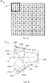
- the color filter array is a Bayer filter.
- a representative example of a Bayer filter suitable for the present embodiments is illustrated in FIG. 2A .
- 'R_ represents a red color filter element
- 'G_ represents a green color filter element
- 'B_ represents a blue color filter color filter element.
- the green information is sampled at a higher frequency.
- Shown in FIG. 2A is an exemplary 21 ⁇ 42 sub-array 30 that includes a red element a green element and two green elements and that corresponds to a picture-element in the image signal.
- color filter arrays e.g., four-color filter, a CY Y M filter array, a CYGM filter array, an RGBW filter array, etc.
- a CY Y M filter array e.g., a CYGM filter array
- RGBW filter array e.g., RGBW filter array
- Imager 20 can alternatively include plurality of pixilated two-dimensional arrays of elementary light detectors, such as, but not limited to, a 3-sensor imager (e.g., a 3-CCD or a 3-CMOS).
- system 10 comprises an optical element that splits the output light beam to plurality of color channel and to direct different color channels to different arrays.
- E ach picture-element of the image signal in these embodiments corresponds to a group of corresponding elementary light detectors in different arrays.
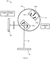
- FIG. 2B is a schematic illustration exemplifying imager 20 in embodiments in which imager 20 comprises a plurality of pixilated 2D arrays of elementary light detectors.
- imager 20 is based on a 3-sensor technology.
- imager 20 comprises an optical element 201 having three prism members 201R, 201G, and 201B , which are bonded together in close contact with one another.
- Element 201 separates the incident light into three color components (R, G and B, in the present example). Bonded interfaces 204 and 205 on prism members 201R , 201G and 201B serve as dichroic mirrors.
- Three pixilated 2D arrays of elementary light detectors 202R, 202G and 202B are individually mounted at the light-outgoing surfaces of the three prism members 201R , 201G and 201B .
- Light beam 18 incident on element 201 is separated by the dichroic mirrors 204, 205 into three color components, shown as light beams 206a , 206b and 206c which are respectively received by their corresponding pixilated 2D arrays.
- Image sensor boards 203R , 203G and 203B pickup signals generated by arrays and optionally perform basic signal processing operations, e.g. , image flip, and the like.
- System 10 also comprises an image processor 22 that receives the image signals from imager 20 (one signal for each output beam in the temporal sequence) and processes the image signals to construct a static spectral image of scene 16.
- Image processor optionally and preferably comprises a hardware circuit, preferably a dedicated hardware circuit, that is constructed to perform the calculations and image processing operations described herein.
- the spectral image typically includes spectral data and spatial data.
- the spatial data is preferably two-dimensional, for example, in the form of a two-dimensional array of picture-elements ( e.g., pixels).
- the spectral data preferably includes a spectrum (for example, a wavelength spectrum) for each picture-element of the spatial data.
- a spectral image is typically a three-dimensional (3D) dataset including two spatial dimensions and one spectral dimension.
- Such dataset is represented mathematically as I(x,y ⁇ ), where x and y are pointers to the picture-elements ( e.g., positions over a rectangular grid), ⁇ the wavelength, and I is the intensity associated with each picture-element and wavelength.
- the advantage of using a color imager in system 10 is that the color information can be gathered substantially without degradation of spatial resolution. It was found by the present Inventor that in spectral imaging it is more difficult than in direct imaging technique to maintain uniformity along the spatial dimensions. It was found by the present Inventor that traditionally acquired spectral images may suffer from various imperfections, including degraded point spread function (PSF), and non-uniformity of intensity and/or focus along the spatial dimensions. The present Inventor also realized that the process of acquiring the data for reconstructing a spectral image is time consuming, and that known techniques to improve speed impose compromises on the spatial and/or spectral resolution of the spectral image.
- PSF degraded point spread function
- Another advantage of using a color imager in system 10 is that it allows generating a color image from the scene while preserving the capability to construct a spectral image with enhanced spatial and spectral resolution.
- Another advantage of using a color imager in system 10 is that it allows relatively fast scanning of large regions in the scene, for example, whole slide imaging in analysis of microscope slides carrying cells and/or tissue for in-vitro imaging.
- Another advantage of using a color imager in system 10 is that it allows performing color analysis and constructing a spectral image on a region-of-interest selected based on this analysis. For example, color analysis can be performed for the purpose of identifying tumor regions on a microscope slides, and a spectral image of these identified tumor regions be successively constructed for advanced quantitative analysis.
- An additional advantage of the system of the present embodiments is that the system can provide a spectral image with reduced or without the effect of visual stri pes corresponding to the interference of the two beams.
- FIGs. 3A-C are schematic illustrations exemplifying several types of optical systems suitable to serve as sequential optical system 12, according to some embodiments of the present invention.
- FIG. 3A schematically illustrates sequential optical system 12 in an embodiment of the invention in which system 12 is an interferometer system.
- system 12 each output light beam 18 constitutes two interfering light beams characterized by optical path difference (OPD) therebetween.
- Controller 26 (not shown, see FIGs. 1A-B ) varies the OPD. This can be achieved by varying the relative position and/or orientation between the scene and one or more components of interferometer system 12, as further detailed hereinbelow.
- FIG. 3A is of a type of interferometer known as the Sagnac type.
- the OPD varies with the angle of incidence of the incoming radiation.
- the OPD increases with the angle of incidence, and the relation between the OPD and the angle of incidence can be approximated as a linear relation.
- embodiments below are described with a particular emphasis to Sagnac interferometer, it is to be understood that embodiments of the present invention can be applied also to many other types of interferometers, such as, but not limited to, a Michelson interferometer, a Mach-Zehnder interferometer, and a Polarimetric interferometer.
- Interferometer system 12 optionally and preferably comprises a lens system 136 through which input light beam 14 passes.
- Lens system 136 preferably collimates beam 14.
- lens system 136 also serves as a magnifying objective lens system.
- the objective lens system can be of any type, including, without limitation, dry, oil-immersion, water-immersion, water-dipped and the like.
- the objective lens system can provide any magnification from 1 ⁇ 41 to 1 ⁇ 4100.
- nput light beam 14 can be reflected from the scene, scattered off objects in the scene, transmitted through the scene or emitted by objects in the scene.
- Interferometer system 12 typically also includes a beam splitter 104 configured to split input light 14 beam into secondary light beams.
- Shown in FIG. 3A are light rays 108 and 110 that are constituted by the secondary light beams.
- each of light rays 108 and 110 can be a central light ray of the respective secondary light beam.
- the secondary light beams themselves are not shown, but the skilled person would know how to adjust the drawing to show the light beam that constitutes each of rays 108 and 110 (for example, by drawing light rays that are parallel to rays 108 and 110 ).
- system 12 comprises two or more reflectors.
- system 12 comprises a pair of reflectors 132 and 134.
- ray 108 is reflected off reflector 132 and ray 110 is reflected off reflector 134.
- ray 108 continues to reflector 134
- ray 108 continues to reflector 132.
- system 12 includes a focusing element 122 that focuses output beam 18 onto imager 20.
- Interferometer system 12 can further comprise a movable block 126 (e.g., a plate or a disc) configured for establishing a motion relative to the scene 16.
- the relative motion can be continuous or i n steps, as desired.
- the relative motion can be a relative rotary motion, e.g. , rotation of beam splitter 104 together with reflectors 132 and 134, and/or a relative translational motion, e.g. , a translational motion of system 12 relative to scene 16.
- a translational motion of scene 16 relative to system 12 is also contemplated, for example, by means of mechanism 24. Further contemplated are embodiments in which a combination of rotary motion and translational motion is employed.
- the relative motion between the scene and the components of the interferometer system is preferably controlled by the controller (not shown in FIG. 3A , see FIGs. 1A-B ).
- the information that is required for calculating the spectrum is contained in the function I(OPD) that expresses the intensity as a function of the OPD.
- one or more pre- and/or post-processing operations can be employed. Representative examples including, without limitation, phase correction, apodization and zero filling. Further details can be found in R.J. Bell, 'Introductory Fourier transform spectroscopy, ' 1972, London: Academic Press .
- An example of a measured interferogram and its derived spectrum, as extracted by Fourier transformation, is shown in FIGs. 4A-B .
- the intensities as a function of the OPD can be obtained by scanning.
- an OPD-scan process is employed.
- the reflectors 132 and 134 and beam splitter 124 are rotated, while all the other optical elements remain static.
- the measurement is preferably executed such that for each small rotation, a single image is captured, until a sufficient number of images are captured.
- the rotation results in a change in the angle for each beam and the pattern travels along the horizontal axis.
- the image itself does not move, so that all the intensities that are measured can be collected for each pixel, and the interferogram can be built.
- the interferograms extracted at each pixel are optionally and preferably Fourier transformed and the collection of spectra of all pixels constructs the spectral image.
- a subset of images within the sequence of the OPD-scan method is shown in FIG. 5 .
- sample-scan process is employed.
- the interferogram is kept fixed, and the sample is scanned, optionally and preferably in a direction orthogonal to the orientation of the interference lines (fringes).
- the image can be shifted, but the interference pattern is fixed.
- the interferogram for each pixel can be constructed based on the pixel-shift from one image to another, wherein the intensities of the detector s pixels are collected.
- the intensities at different OPDs are collected. This can be followed by Fourier transformation and construction of the spectral image.
- FIG. 6 A subset of images within the sequence of the sample-scan method is shown in FIG. 6 .
- FIGs. 3B and 3C are schematic illustrations of system 12 in embodiments in which sequential optical system 12 comprises a tunable filter.
- FIG. 3B illustrates an embodiment in which light source 28 generates input light beam 14 characterized by a wide spectral range.
- Beam 14 enters a tunable optical filter 140 (for example, acoustooptic tunable filter, liquid crystal tunable filter, etc.).
- Controller 26 commands filter 140 to tune to the first central wavelength.
- Filter 140 filters out a portion of the spectrum of beam 14 so that the spectrum of the output beam 18 exiting filter 140 is narrower than the spectrum of beam 14. Controller 26 then commands filter 140 to tune to the next wavelength and so that another output beam is generated.
- FIG. 3C illustrates an embodiment in which light source 28 generates source light beam 15 characterized by a wide spectral range. Beam 15 passes through the scene 16 to form input light beam 14 that describes the scene. Beam 14 enters tunable optical filter 140. Controller 26 commands filter 140 to tune to the first central wavelength. Filter 140 filters out a portion of the spectrum of beam 14 so that the spectrum of the output beam 18 exiting filter 140 is narrower than the spectrum of beams 15 and 14. Controller 26 then commands filter 140 to tune to the next wavelength and so that another output beam is generated. The output beams 18 continue from filter 140 to imager 20, for example, using a lens system (not shown).
- a sufficient number of intensities I each measured at a different value of the optical parameter range e.g., a different OPD of the interferometer, or a different characteristic central wavelength of the tunable filter
- a sufficient number of intensities I each measured at a different value of the optical parameter range e.g., a different OPD of the interferometer, or a different characteristic central wavelength of the tunable filter
- the image processor preferably converts the image data constituted by the image signals to greyscale levels that represent the intensities I. This can be done in more than one way.
- imager 20 comprises a filter array
- the conversion can comprise binning of neighboring picture-elements in a non-overlapping manner.
- the binning "non-overlapping" in the sense that the intensity provided by each elementary light detector of the array is not used for determining the greyscale level of more than one picture-element.
- a representative example of non-overlapping binning is a process in which sub-array is integrated or summed and the result of this integration can be assigned as the greyscale level of the corresponding picture-element.
- the binning operation reduces the spatial resolution so that the number of resultant greyscale elements of the detector array is divided by a factor of 4.
- An alternative technique for converting the image data to greyscale levels includes, for each light detector of the array, integrating data received from light detector neighbori ng that detector and assigni ng to a picture-element correspondi ng to that detector a greyscale level based on the integration.
- a representative example of such an embodiment is a process in which a sub-array is integrated or summed and the result of this integration is assigned as the greyscale level of a picture-element that corresponds to one light detector (e.g., the upper-left light detector) of that sub-array. This maintains the spatial resolution of the light detector array.
- imager 20 comprises a plurality of pixilated 2D arrays of elementary light detectors ( e.g. , as illustrated in FIG. 2B )
- the conversion of image data to greyscale levels can be achieved, by integrating, for each picture-element, over color channels obtained from respective elementary light detectors of the 2D arrays and being associated with that picture-element, and assigning to the picture-element a greyscale level based on the integration.
- the greyscale level of the picture-element at position (x, y) can set to be R(x,y)+G(x,y)+B(x,y), where R(x,y), G(x,y) and B(x,y) are, respectively, the intensities measured by the elementary light detectors at position (x, y) of the first, the second and the thi rd arrays.
- the image processor optionally corrects the intensity level of each of at least some of the picture-elements of the spectral image using local intensity associated with a respective color channel in the image data constituted by the image signals.
- the correction is optionally and preferably features a local correction factor that represents the ratio between the local intensity and the integrated intensity at each picture-element to which the correction is applied.
- C s x y l R s x y l I s x y ⁇ I x , y
- R s ( x,y,l ) is the measured spectrum at the picture-element located at (x, y)
- I x,y is the intensity of the picture-element located at (x, y).
- I x,y is obtained by direct imaging technique, as described hereinunder with reference to FIG. 8 .
- I x,y is obtained by indirect imaging technique as described hereinunder with reference to FIG. 7 . It was found by the present inventors that the corrected spectral image C s ( x,y, ⁇ ) has high spatial quality in terms of spatial sharpness and correct intensity representation without degrading the local spectral signature representation of image el ements.
- imager 20 is a color imager
- the advantage of these embodiments is that they provide i mage smoothness. For example, when there are, say, a red color channel, a green color channel and a blue color channel, it is preferred to maintain, locally, for at least some regions within the image, the ratio between the intensities of the red, green and blue sub-spectra that are stored in the red, green and blue picture-elements that compose that region. This is preferably achieved by applying an intensity correction factor as will now be explained.
- imager 20 includes a filter array (e.g. , as described above with respect to FIG. 2A )
- the image processor applies, for each picture-element that correspond to a color channel, an intensity correction factor selected to ensure that a ratio between the intensity corresponding to that color channel and the integrated intensity corresponding to the color channels at a region containing the picture-element is preserved.
- an intensity correction factor selected to ensure that a ratio between the intensity corresponding to that color channel and the integrated intensity corresponding to the color channels at a region containing the picture-element is preserved.
- a uniform image area can be used and the values of each color channel (e.g., red, green and blue color cannels) can be stored.
- T hen the total intensity as well as the ratio between the intensities of the individual color channels is maintained within the spectrum of each picture-element.
- L et I G 1 be the intensity value measured by the elementary light detector that is at location (x,y), and that is behi nd a green element of the Bayer array.
- the expression I S ⁇ l S ( l ) dl is the integrated intensity of the spectrum over the 2 1 ⁇ 4 2 sub-array containing the location (x,y), and therefore represents the non-corrected intensity of the spectrum at location (x,y).
- the expression I S G 1 ⁇ / S / ⁇ S G / d / , where S G ( l ) is the characteristic spectral sensitivity of the elementary light detectors behind the green elements of the array sensor, is the partial intensity that corresponds to the green channel.
- I RGB be a greyscale level intensity as provided by a binning or summing procedure applied to the 2 1 ⁇ 4 2 region containing the location (x,y).
- I RGB is a combination (linear or non-linear) of the intensities picked by the individual detector elements at the respective 2 1 ⁇ 4 2 region.
- all values of the coefficients a i are the same (in which case I RGB is a non-weighted sum of intensities), and in other embodiments at least two of the coefficients a i are different from each other (in which case I RGB is a weighted sum of intensities).
- ratio between the intensity of a picture-element (e.g., a pixel) and the integrated intensity of a sub-array of the filter array (e.g., a 21 ⁇ 42 sub-array) approximately equals the ratio between the corresponding intensities in the spectral image.
- a similar procedure can be applied to image signal provided by an imager having other types of filter arrays.
- the image processor 22 can apply image uniformity correction to spatial information in the spectral image, for reducing or eliminate non-uniformity in the two spatial dimensions of the spectral image. This improves the intensity normalization of the image.
- Image uniformity correction can be applied either before the construction of the spectral image, for example, directly on the image signal provided by the imager, or after the construction of the spectral image, by applying the correction to the two spatial dimensions namely of I(x, y, l).
- Image uniformity correction can also be applied to an image signal provided by imager 20 in response to direct imaging wherein light beams incident on imager 20 without passing through system 12 .
- the result of the image uniformity correction applied to the signal obtained by direct imaging can be used as a reference to the image uniformity correction applied to image signals generated in response to light passing through system 12 .
- the reference image signal R can be obtained, for example, by imaging a reference scene for which the uniformity level is known. Typically, but not necessarily, R is obtained by imaging a white scene.
- the system of the present embodiments can also be used for obtaining a 2D color image of the scene, wherein the 2D image includes color information generated by the color imager 20 , but not by the sequential optical system.
- the number of color channels of the color image in these embodiments is equal to or less than the number of color cannels providable by imager 20 .
- the 2D image is captured from a single output light beam exiting system 12 .
- a color 2D image captured in this way is referred to as an "indirect color image," because it is captured after the light beam from the light source or scene has passed through system 12 .
- system 12 comprises an interferometer system
- the output light beam provided by system 12 constitutes an interference pattern also referred to as a fringe pattern.
- image processor 22 reduces the amplitudes of fringe pattern. This can be achieved by operating locomotion mechanism 24 ( e.g. , by controller 26 ) to shift a relative position between scene 16 and system 12 , wherein image processor is 12 extracts, for each relative position, a portion of the image in which the fringe pattern amplitudes are reduced relative to other portions of the image.
- FIG. 7 The process is illustrated in FIG. 7 , which exemplify five images 702a-702e captured by imager 20 , wherein each image correspond to a different position of scene 16 relative to system 12 .
- Respectively marked on images 702a-702e are regions of interest (ROIs) 704a-704e .
- the ROIs are preferably off-center relative to images 702a-702e , since in the off-center parts of the images the amplitudes of the fringe pattern are reduced, relative to the center.
- the position, shape and size, relative to images 702a-702e , of each of ROIs 704a-704e is the same.
- the processor 22 extracts the portions of the images that are encompassed by the respective ROIs, and tiles the extracted portions.
- the tiling process comprises removing periodic parts of in the extracted portions. This can be done, for example, by applying a 2D-Fourier-Transform technique, as disclosed in, e.g. , Digital Image Processing, Rafael C. Gonzalez, Richard E. Woods, 1993, pp, 201-213 .
- direct imaging a technique referred to herein as "direct imaging".
- direct imaging a color 2D image is captured from light beam that does not pass through system 12 .
- a color 2D image captured in this way is referred to as "direct image”.
- FIG. 8 A representative illustration of a configuration that allows capturing a direct image is illustrated in FIG. 8 .
- the schematic illustration is for the case in which in embodiments in which system 12 comprises an interferometer system, but the ordinarily skilled person would know how to adjust the description for other types of sequential optical systems.
- FIG. 8 Shown in FIG. 8 is a configuration in which system 12 (an interferometer system, in the present example) as well as an additional optics 720 are mounted on the same movable block 126 .
- Optics 720 is typically a redirecting optics constituted for redirecting input light beam 14 directly onto imager 20, preferably via focusing element 122 so that beam 14 is focused on imager 20 .
- the switching between indirect imaging (via system 12 ) and direct imaging (not via system 12 ) can be achieved by rotating block 126 .
- optics 720 and system 12 are antipodal so that the switching is achieved by a 180 rotation of block 126, but other switching scenarios are also contemplated.
- the switching e.g., rotation of block 126
- Image processor 22 receives the image signal generated by imager 20 responsively to the direct focus, and provides a color image of scene 16 based on the image signal.
- compositions, method or structure may include additional ingredients, steps and/or parts, but only if the additional ingredients, steps and/or parts do not materially alter the basic and novel characteristics of the claimed composition, method or structure.
- a compound or “at least one compound” may include a plurality of compounds, including mixtures thereof.
- range format is merely for convenience and brevity and should not be construed as an inflexible limitation on the scope of the invention. Accordingly, the description of a range should be considered to have specifically disclosed all the possible subranges as well as individual numerical values within that range. For example, description of a range such as from 1 to 6 should be considered to have specifically disclosed subranges such as from 1 to 3, from 1 to 4, from 1 to 5, from 2 to 4, from 2 to 6, from 3 to 6 etc., as well as individual numbers within that range, for example, 1, 2, 3, 4, 5, and 6. T his applies regardless of the breadth of the range.
- a prototype spectral imaging system having an interferometer system as a sequential optical system, an RGB color imager, and a stage for switching between direct and indirect imaging has been constructed. Images captured by the prototype system are shown in FIGs. 9A-12B .
- FIGs. 9A-F show images captured by a color imager having a Bayer filter array within a sequence of an OPD-scan, where FIGs. 9A-9C are the color images as captured by the color imager, and FIGs. 9D-9F are the corresponding images after the image data has been converted to greyscale levels;
- FIGs. 10A-F show images captured by a color imager having a Bayer filter array within a sequence of a sample-scan, where FIGs. 10A-10C are the color images as captured by the color imager, and FIGs. 10D-10F are the corresponding images after the image data has been converted to greyscale levels;
- FIG. 11A is color image of the sample, obtained by direct imaging, FIG.
- FIG. 11B is a magnified region-of-interest over the color image of FIG. 9A
- FIG. 11C is a greyscale image obtained by converting the three color channels of FIG. 11B into greyscale levels by a binning procedure
- FIG. 12A shows a greyscale image obtained by indirect imaging
- FIG. 12B shows the image of FIG. 12A after removal of fringe pattern amplitude.
Landscapes
- Physics & Mathematics (AREA)
- Spectroscopy & Molecular Physics (AREA)
- General Physics & Mathematics (AREA)
- Engineering & Computer Science (AREA)
- Power Engineering (AREA)
- Signal Processing (AREA)
- Multimedia (AREA)
- Electromagnetism (AREA)
- Condensed Matter Physics & Semiconductors (AREA)
- Computer Hardware Design (AREA)
- Microelectronics & Electronic Packaging (AREA)
- Optics & Photonics (AREA)
- Theoretical Computer Science (AREA)
- Color Television Image Signal Generators (AREA)
Applications Claiming Priority (1)
| Application Number | Priority Date | Filing Date | Title |
|---|---|---|---|
| US201562267360P | 2015-12-15 | 2015-12-15 |
Publications (2)
| Publication Number | Publication Date |
|---|---|
| EP3190394A2 true EP3190394A2 (fr) | 2017-07-12 |
| EP3190394A3 EP3190394A3 (fr) | 2017-11-15 |
Family
ID=57714371
Family Applications (1)
| Application Number | Title | Priority Date | Filing Date |
|---|---|---|---|
| EP16204270.9A Withdrawn EP3190394A3 (fr) | 2015-12-15 | 2016-12-15 | Systèmes et procédés d'imagerie spectrale |
Country Status (2)
| Country | Link |
|---|---|
| US (1) | US11012643B2 (fr) |
| EP (1) | EP3190394A3 (fr) |
Families Citing this family (3)
| Publication number | Priority date | Publication date | Assignee | Title |
|---|---|---|---|---|
| JP7095693B2 (ja) * | 2017-05-30 | 2022-07-05 | ソニーグループ株式会社 | 医療用観察システム |
| JP2020020675A (ja) * | 2018-08-01 | 2020-02-06 | ソニーセミコンダクタソリューションズ株式会社 | 計測装置 |
| US11624656B2 (en) * | 2021-04-12 | 2023-04-11 | Viavi Solutions Inc. | Optical filter for an optical sensor device |
Citations (2)
| Publication number | Priority date | Publication date | Assignee | Title |
|---|---|---|---|---|
| US3971065A (en) | 1975-03-05 | 1976-07-20 | Eastman Kodak Company | Color imaging array |
| US5539517A (en) | 1993-07-22 | 1996-07-23 | Numetrix Ltd. | Method for simultaneously measuring the spectral intensity as a function of wavelength of all the pixels of a two dimensional scene |
Family Cites Families (23)
| Publication number | Priority date | Publication date | Assignee | Title |
|---|---|---|---|---|
| US5991028A (en) * | 1991-02-22 | 1999-11-23 | Applied Spectral Imaging Ltd. | Spectral bio-imaging methods for cell classification |
| US6198532B1 (en) * | 1991-02-22 | 2001-03-06 | Applied Spectral Imaging Ltd. | Spectral bio-imaging of the eye |
| US6711283B1 (en) * | 2000-05-03 | 2004-03-23 | Aperio Technologies, Inc. | Fully automatic rapid microscope slide scanner |
| JP3918499B2 (ja) * | 2000-11-01 | 2007-05-23 | セイコーエプソン株式会社 | 間隙測定方法、間隙測定装置、形状測定方法、形状測定装置並びに液晶装置の製造方法 |
| JP2007033217A (ja) | 2005-07-26 | 2007-02-08 | Keyence Corp | 干渉計測装置及び干渉計測方法 |
| US20070140553A1 (en) * | 2005-12-19 | 2007-06-21 | Olympus Corporation | Dental colorimetry apparatus |
| US7706606B1 (en) * | 2006-05-31 | 2010-04-27 | Adobe Systems Incorporated | Fast, adaptive color to grayscale conversion |
| CN101506826A (zh) * | 2006-07-19 | 2009-08-12 | 光谱辨识公司 | 多重生物测定多谱成像器 |
| US20080158396A1 (en) * | 2006-08-07 | 2008-07-03 | Transchip, Inc. | Image Signal Processor For CMOS Image Sensors |
| DE102007026595A1 (de) | 2007-06-08 | 2008-12-18 | Fraunhofer-Gesellschaft zur Förderung der angewandten Forschung e.V. | Vorrichtung und Verfahren zur Kompensation von Farbverschiebungen in faseroptischen Abbildungssystemen |
| US8849380B2 (en) * | 2007-11-26 | 2014-09-30 | Canfield Scientific Inc. | Multi-spectral tissue imaging |
| IL189020A (en) * | 2008-01-24 | 2015-08-31 | Rafael Advanced Defense Sys | A method and device for multi-spectral imaging |
| WO2009116359A1 (fr) | 2008-03-17 | 2009-09-24 | 国立大学法人東京農工大学 | Dispositif de mesure de surface de contact et procédé pour mesurer une surface de contact |
| US8374801B2 (en) * | 2009-01-09 | 2013-02-12 | Chemimage Corporation | Automation of ingredient-specific particle sizing employing raman chemical imaging |
| US20100195162A1 (en) * | 2009-02-05 | 2010-08-05 | Peter Majewicz | Color To Monochrome Conversion |
| GB2485209B (en) * | 2010-11-05 | 2015-11-04 | Inst Medical Informatics | Microscopy analysis technique |
| US20130188181A1 (en) | 2011-10-18 | 2013-07-25 | Stanley Michael Angel | Systems and Methods for Spatial Heterodyne Raman Spectroscopy |
| US9357975B2 (en) | 2013-12-30 | 2016-06-07 | Carestream Health, Inc. | Large FOV phase contrast imaging based on detuned configuration including acquisition and reconstruction techniques |
| WO2014190027A1 (fr) * | 2013-05-22 | 2014-11-27 | Massachusetts Institute Of Technology | Procédés, systèmes et appareil de radiométrie spectrale imageante |
| US9171203B2 (en) * | 2013-09-10 | 2015-10-27 | Dropbox, Inc. | Scanbox |
| US9719777B1 (en) * | 2014-05-30 | 2017-08-01 | Zygo Corporation | Interferometer with real-time fringe-free imaging |
| US10481095B2 (en) * | 2014-06-05 | 2019-11-19 | Universität Heidelberg | Methods and means for multispectral imaging |
| US10061972B2 (en) * | 2015-05-28 | 2018-08-28 | Tokitae Llc | Image analysis systems and related methods |
-
2016
- 2016-12-15 US US15/379,519 patent/US11012643B2/en active Active
- 2016-12-15 EP EP16204270.9A patent/EP3190394A3/fr not_active Withdrawn
Patent Citations (2)
| Publication number | Priority date | Publication date | Assignee | Title |
|---|---|---|---|---|
| US3971065A (en) | 1975-03-05 | 1976-07-20 | Eastman Kodak Company | Color imaging array |
| US5539517A (en) | 1993-07-22 | 1996-07-23 | Numetrix Ltd. | Method for simultaneously measuring the spectral intensity as a function of wavelength of all the pixels of a two dimensional scene |
Non-Patent Citations (4)
| Title |
|---|
| R.J. BELL: "Introductory Fourier transform spectroscopy", 1972, ACADEMIC PRESS |
| RAFAEL C. GONZALEZ; RICHARD E. WOODS, DIGITAL IMAGE PROCESSING, 1993, pages 201 - 213 |
| Y. GARINI; I.T. YOUNG; G. MCNAMARA: "Spectral imaging: principles and applications.", CYTOMETRY, vol. 69A, 2006, pages 735 - 747 |
| Y. GARINI; N. KATZIR; D. CABIB; R.A. BUCKWALD; D.G. SOENKSEN; Z. MALIK: "Fluorescence Imaging Spectroscopy and Microscopy", 1996, JOHN WILEY AND SONS, article "Spectral Bio-Imaging", pages: 87 - 124 |
Also Published As
| Publication number | Publication date |
|---|---|
| EP3190394A3 (fr) | 2017-11-15 |
| US11012643B2 (en) | 2021-05-18 |
| US20170171476A1 (en) | 2017-06-15 |
Similar Documents
| Publication | Publication Date | Title |
|---|---|---|
| EP3830551B1 (fr) | Imageur spectral hybride | |
| US8351031B2 (en) | Single-shot spectral imager | |
| JP6524617B2 (ja) | 撮像装置および方法 | |
| JP6314232B2 (ja) | 多機能イメージャ | |
| JP7045379B2 (ja) | 仮現運動における物体の動的ハイパースペクトルイメージング | |
| US9239263B2 (en) | Image mapped spectropolarimetry | |
| US7768641B2 (en) | Spatial image modulation to improve performance of computed tomography imaging spectrometer | |
| JP7538624B2 (ja) | 時間分解ハイパースペクトル単一画素撮像 | |
| WO2016011675A1 (fr) | Système d'imagerie hyperspectrale à large bande à détection compressée à base de réseau aléatoire | |
| US20150116705A1 (en) | Spectral imager | |
| Kuckein et al. | sTools–a data reduction pipeline for the GREGOR Fabry-Pérot Interferometer and the High-resolution Fast Imager at the GREGOR solar telescope | |
| US11012643B2 (en) | System and method for spectral imaging | |
| EP3877734B1 (fr) | Procédé et système de polarimétrie faisant appel à une manipulation de polarisation géométrique statique | |
| CN206281570U (zh) | 基于阶跃滤光片的超光谱成像仪 | |
| Hahn et al. | Detailed characterization of a hyperspectral snapshot imager for full-field chromatic confocal microscopy | |
| CN112097904A (zh) | 基于衍射透镜/变焦透镜阵列的光谱成像系统及方法 | |
| WO2007070610A2 (fr) | Spectrometre d'imagerie par tomodensitometrie a appareil de prise de vues en couleur pour une precision d'image spectrale spatiale amelioree | |
| US20160033330A1 (en) | Spectral imaging using single-axis spectrally dispersed illumination | |
| US9915565B2 (en) | Method and system for spectral imaging | |
| US20090310877A1 (en) | Lossless Compression Process for Interferograms | |
| Barducci et al. | Simulation of the performance of a stationary imaging interferometer for high-resolution monitoring of the Earth | |
| Mansur et al. | Fiber optic snapshot hyperspectral imager | |
| US20230304925A1 (en) | Field calibration for near real-time fabry perot spectral measurements | |
| Hubold et al. | System calibration and characterization of an ultra-compact multispectral snapshot imaging system | |
| Claudi et al. | First science with SPHERE |
Legal Events
| Date | Code | Title | Description |
|---|---|---|---|
| PUAI | Public reference made under article 153(3) epc to a published international application that has entered the european phase |
Free format text: ORIGINAL CODE: 0009012 |
|
| STAA | Information on the status of an ep patent application or granted ep patent |
Free format text: STATUS: REQUEST FOR EXAMINATION WAS MADE |
|
| 17P | Request for examination filed |
Effective date: 20161215 |
|
| AK | Designated contracting states |
Kind code of ref document: A2 Designated state(s): AL AT BE BG CH CY CZ DE DK EE ES FI FR GB GR HR HU IE IS IT LI LT LU LV MC MK MT NL NO PL PT RO RS SE SI SK SM TR |
|
| AX | Request for extension of the european patent |
Extension state: BA ME |
|
| PUAL | Search report despatched |
Free format text: ORIGINAL CODE: 0009013 |
|
| AK | Designated contracting states |
Kind code of ref document: A3 Designated state(s): AL AT BE BG CH CY CZ DE DK EE ES FI FR GB GR HR HU IE IS IT LI LT LU LV MC MK MT NL NO PL PT RO RS SE SI SK SM TR |
|
| AX | Request for extension of the european patent |
Extension state: BA ME |
|
| RIC1 | Information provided on ipc code assigned before grant |
Ipc: H04N 5/33 20060101ALI20171006BHEP Ipc: G01J 3/28 20060101ALI20171006BHEP Ipc: G01J 3/26 20060101ALI20171006BHEP Ipc: H01L 27/146 20060101ALI20171006BHEP Ipc: G01B 9/02 20060101ALI20171006BHEP Ipc: G02B 26/00 20060101ALI20171006BHEP Ipc: G01J 3/51 20060101AFI20171006BHEP Ipc: G01J 3/453 20060101ALI20171006BHEP Ipc: H04N 9/04 20060101ALI20171006BHEP Ipc: G06T 5/00 20060101ALI20171006BHEP |
|
| STAA | Information on the status of an ep patent application or granted ep patent |
Free format text: STATUS: THE APPLICATION IS DEEMED TO BE WITHDRAWN |
|
| 18D | Application deemed to be withdrawn |
Effective date: 20210701 |