EP3190002A1 - Warenbewegungsvorrichtung - Google Patents
Warenbewegungsvorrichtung Download PDFInfo
- Publication number
- EP3190002A1 EP3190002A1 EP17152979.5A EP17152979A EP3190002A1 EP 3190002 A1 EP3190002 A1 EP 3190002A1 EP 17152979 A EP17152979 A EP 17152979A EP 3190002 A1 EP3190002 A1 EP 3190002A1
- Authority
- EP
- European Patent Office
- Prior art keywords
- trailer
- goods
- storage area
- opening
- moved
- Prior art date
- Legal status (The legal status is an assumption and is not a legal conclusion. Google has not performed a legal analysis and makes no representation as to the accuracy of the status listed.)
- Withdrawn
Links
- 229910000831 Steel Inorganic materials 0.000 claims description 2
- 239000010959 steel Substances 0.000 claims description 2
- 230000000712 assembly Effects 0.000 description 1
- 238000000429 assembly Methods 0.000 description 1
- 238000000034 method Methods 0.000 description 1
Images


Classifications
-
- B—PERFORMING OPERATIONS; TRANSPORTING
- B65—CONVEYING; PACKING; STORING; HANDLING THIN OR FILAMENTARY MATERIAL
- B65G—TRANSPORT OR STORAGE DEVICES, e.g. CONVEYORS FOR LOADING OR TIPPING, SHOP CONVEYOR SYSTEMS OR PNEUMATIC TUBE CONVEYORS
- B65G69/00—Auxiliary measures taken, or devices used, in connection with loading or unloading
- B65G69/22—Horizontal loading or unloading platforms
- B65G69/24—Horizontal loading or unloading platforms having platform level adjusting means
-
- B—PERFORMING OPERATIONS; TRANSPORTING
- B60—VEHICLES IN GENERAL
- B60P—VEHICLES ADAPTED FOR LOAD TRANSPORTATION OR TO TRANSPORT, TO CARRY, OR TO COMPRISE SPECIAL LOADS OR OBJECTS
- B60P1/00—Vehicles predominantly for transporting loads and modified to facilitate loading, consolidating the load, or unloading
- B60P1/44—Vehicles predominantly for transporting loads and modified to facilitate loading, consolidating the load, or unloading having a loading platform thereon raising the load to the level of the load-transporting element
- B60P1/4414—Vehicles predominantly for transporting loads and modified to facilitate loading, consolidating the load, or unloading having a loading platform thereon raising the load to the level of the load-transporting element and keeping the loading platform parallel to the ground when raising the load
- B60P1/4421—Vehicles predominantly for transporting loads and modified to facilitate loading, consolidating the load, or unloading having a loading platform thereon raising the load to the level of the load-transporting element and keeping the loading platform parallel to the ground when raising the load the loading platform being carried in at least one vertical guide
-
- B—PERFORMING OPERATIONS; TRANSPORTING
- B65—CONVEYING; PACKING; STORING; HANDLING THIN OR FILAMENTARY MATERIAL
- B65G—TRANSPORT OR STORAGE DEVICES, e.g. CONVEYORS FOR LOADING OR TIPPING, SHOP CONVEYOR SYSTEMS OR PNEUMATIC TUBE CONVEYORS
- B65G67/00—Loading or unloading vehicles
- B65G67/02—Loading or unloading land vehicles
-
- B—PERFORMING OPERATIONS; TRANSPORTING
- B65—CONVEYING; PACKING; STORING; HANDLING THIN OR FILAMENTARY MATERIAL
- B65G—TRANSPORT OR STORAGE DEVICES, e.g. CONVEYORS FOR LOADING OR TIPPING, SHOP CONVEYOR SYSTEMS OR PNEUMATIC TUBE CONVEYORS
- B65G2814/00—Indexing codes relating to loading or unloading articles or bulk materials
- B65G2814/03—Loading or unloading means
Definitions
- the invention to which this application relates is in relation to apparatus for use in the movement of goods.
- the invention is for use in the movement of goods between storage areas, such as a first storage area in the form of a warehouse and a second, movable goods storage area in the form of, for example, a vehicle trailer provided as part of, or in connection with, a vehicle.
- the movement of goods across a geographical area is most commonly achieved by vehicles which have a trailer in which goods are stored and moved.
- the goods may be separate items, such as parcels or the like, or may be grouped together and moved on pallets, trolleys, wheeled cages, or the like.
- there is a need for the goods to be unloaded from, and loaded onto, the trailer most typically at a location such as a warehouse and a loading bay provided as part of the same.
- the apparatus of the type to which the application relates includes a lifting platform which is vertically movable with respect a support frame.
- the goods can be lifted and lowered on the platform with respect to the support frame to allow the platform to be brought to the desired floor height of an adjacent goods storage area, and which floors are often provided at different heights. Once the platform is at the appropriate height, the goods can be moved to and from the adjacent floor which is at the same height.
- the support frame is located such that one end of the platform is locatable adjacent an edge of a floor of a first of the goods storage areas and the opposing end of the platform is locatable adjacent an edge of a floor of the second of the goods storage areas.
- EP1775246 discloses apparatus of this type.
- a problem which is experienced with apparatus of this type is how to bridge a gap which exists between the edge of the platform and the edge of the adjacent floor, and, in particular, the floor of the transportable storage area.
- typically the goods are moved through an opening at an end of the transportable goods storage area and that typically the opening is relatively narrow and confined, which is especially the case if there is provided a tail lift assembly and/or door assembly at the opening.
- a tail lift assembly When a tail lift assembly is provided a portion of the same can be moved to an extended position outwardly from and externally of the opening and into a horizontal plane so that the portion provides a limited floor space to allow goods to be moved onto the same and then be moved to ground level, typically at a location for delivery of the goods such as to a retail unit.
- the doors which are provided to selectively open and close the opening can take several forms but one possible group is the form in which the door is linearly movable and provided as a shutter or in the form defined in the applicant's co-pending application number EP2732999 in which there are provided first and second door panels which are linearly movable to allow selective access to portions of the opening into the trailer and typically to allow access to a floor of the trailer at a first height and, by movement of the door panels, to allow access to a floor at a spaced height above the first floor in the trailer.
- this door apparatus at the opening and positioned between the end of the storage area frame and the end of at least the raised floor of the trailer, and the confined size of the opening, means that the bridging of the gap between the respective edges of the floor of the storage area and platform of the lifting apparatus is difficult to achieve and is currently not safely possible in a manner which allows a secure and sufficiently supported access path, especially when one considers the weight of the goods which may be moved across the same and the requirement to allow safe passage of personnel across the same.
- a first aim of the invention is therefore to provide apparatus and a method which allows the said gap to be bridged safety and repeatedly and a further aim of the invention is to provide a means of moving components to allow the operation of lifts at the opening to another location in the goods storage area whilst ensuring that the lifts or doors operate efficiently.
- a further aim is to provide the apparatus at the opening of the transportable storage area in a manner which minimises the impact on access through the opening.
- a transportable goods storage trailer said trailer including a goods storage area defined by opposing side walls, a roof, at least one floor, a first end and a second end in which an opening is provided to allow goods to be moved therethrough into and from the interior of the goods storage area, a tail lift apparatus mounted on the trailer and the tail lift includes a portion at, and located externally of, the said opening and which is movable in a linear direction along guide means to alter the height of the same, and to allow the same to be deployed between in use and storage positions and characterised in that powered drive apparatus to allow the said portion to be moved is located at or towards the said first end of the goods storage area and is connected to the said portion via one or more elongate members which pass along the interior of the goods storage area.
- the portion is movable between a substantially horizontal in-use position and a substantially vertical storage position by pivotal movement about an axis.
- the portion when the portion is in the in-use position the portion can be stood on and/or goods moved onto and from the same and the portion moved vertically.
- the guide means are mounted on the frame of the trailer.
- the powered drive apparatus includes a hydraulic ram and hydraulic control system and they and the components for the same are located at the first end of the trailer.
- the elongate members pass along the underside of the roof of the trailer and are located via pulley wheels.
- a door assembly is provided on the trailer at the opening.
- the support means is provided as part of the goods storage area and the support means and the edge of the floor define opposing side walls of a passage through which at least a portion of the door assembly can pass.
- At least one, but typically both, of the bridging portions are pivotally movable between a storage position and an in use position in which the same form a path between the platform and the floor and allow the passage of goods and/or personnel thereacross.
- both of the first and second portions are provided in contact with the support means when they are in the in use position.
- At least part of the support means is movable into a position to support at least one of the bridging portions when in the in use position.
- the support means are provided in a fixed position.
- the support means are provided as an integral part of the chassis of the goods storage area.
- the door assembly is a sliding door assembly such as a shutter door or the door assembly in the applicant's co pending patent application EP2732999 .
- the door of the assembly is movable in a linear direction to allow the opening to be opened or closed.
- the door may be formed from a number of portions which can be selectively moved to allow selective access to portions of the opening.
- the bridging portion connected to the platform is provided for powered movement between the in use and storage positions and the bridging portion connected to the goods storage area is provided to be capable of movement under the influence of the movement and/or position of the door assembly mounted thereon.
- the vehicle trailer can be moved into position such that the opening through which the goods are to be moved is positioned adjacent to the said edge of the platform of the lifting apparatus.
- the bridging portion attached to the platform is first movable into contact with the support means once the goods storage is in position and can be moved into position prior to the door assembly of the goods storage area being moved to an open position.
- the door assembly can be moved to the open position and the bridging portion of the goods storage area is then free to be moved to the in use position in contact with the support means.
- the tail lift can be moved to an in use position when the goods storage area is at a location which is remote from the lifting apparatus.
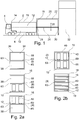
- FIG. 1 there is illustrated a movable goods storage area in the form of a vehicle trailer 2 which is located on and movable by a vehicle 4 in a conventional manner.
- the goods storage area in this embodiment, is defined by side walls 6,8 a floor 10, a raised floor 12, roof 15, a first end wall 14 and an opposing end 16 in which there is provided an opening 18.
- the opening when open, allows the movement of goods into and from the goods storage area 2 and the goods are moved onto and from lifting apparatus 20.
- the lifting apparatus includes a frame 22 which is provided in a fixed position and on which is mounted a platform 24 and which is movable in the vertical direction indicated by arrow 26 to bring the platform to the height of the required floor 10,12.
- a first edge 28 of the platform is positioned such that the end 16 of the trailer 2 can be brought adjacent to the same.
- a second goods storage area in the form of a warehouse 32 such that the lifting apparatus allows the movement of goods between the first and second goods storage areas 2 and 32.
- the trailer end 16 is provided with a door assembly 34 to allow the selective opening and closing of the opening 18 and two examples of this are provided in Figures 2a and b.
- Figure 2a there is provided an assembly in accordance with the applicant's copending application EP2732999 .
- two door portions 36,38 which are independently movable so that the assembly can be provided in a position to fully close the opening as shown in (i), a first open position as shown in (ii) to allow access to a lower floor 10 of the trailer and goods thereon and a second opened position as shown in (iii) to allow access to the higher floor 12 of the trailer and goods thereon.
- FIG. 2b A second form of door assembly is shown in Figure 2b in which the door assembly is a shutter door 40 which has a free end 42 which can be moved from the open position adjacent the top of the opening as shown at (i) to the closed position at the floor 10 of the opening as shown at (ii).
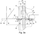
- the gap 46 is bridged by the provision of a first bridging portion 48 provided on the platform 24 and a second bridging portion 50, provided on the floor 12 as shown in Figures 3a and b.
- the bridging portions 48, 50 are each pivotally movable about respective pivot axes 62, 64 between storage positions shown in broken lines at 48, 50 and in use positions shown at 48', 50', When the portions are in the positions 48', 50' so a goods movement path is provided which allows the goods to be moved between the platform 24 and the floor 12 as indicated by arrow 58.
- a support means 60 is provided in the form of one or more elongate beams which typically extend across the width of the opening and which are joined at their opposing ends 63,65 as shown in Figures 2a and b to the frame of the trailer 2 at the opening 16 so that they form an integral part thereof.
- the location of the support means ensures that there is still provided the space 52 between the support means 60 and the edge of the floor 12 such that the door assembly can still be moved when required through the space.
- Further support members 66 may be provided as part of the trailer frame if required.
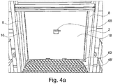
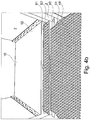
- FIGs 4a and b illustrate the manner in which the apparatus may be deployed, with the view shown being from the platform 24 looking towards the end 16 of the trailer 2 which has been brought into position for loading/unloading via the platform 24..
- the bridging portions 48, 50 are in the storage position shown in broken lines in Figure 3 and with the door assembly 34 of the opening 18 in the closed position shown in Figures 2a(i) .
- Figure 4a it will be seen in Figure 4a how the bridging portion 48 of the platform can be moved down to the in use position 48' as shown to contact with the support means 60 of the trailer 2 with the door assembly 34 closed and hence the opening 18 still closed.
- the bridging portion can be moved to the storage position 50, thereby allowing the door assembly 34 to be moved back to the closed position through the space 52 which is then available again.
- FIGs 5a and b illustrate a side elevation of a storage area trailer 2, with, in Figure 5a the top or roof 15 of which is shown in broken lines. At the end 16 of the same there is again provided an opening 18 with a space 52 in which the door assembly 34 can be moved between open and closed position as indicated by arrow 70.
- the trailer 2, at end 16 is also fitted with a tail lift assembly 80 with a portion 82 shown in Figure 5b , provided to be movable between a substantially horizontal in use position as shown and a vertical storage position by pivotal movement about axis 84 and as indicated by arrow 86 in a conventional manner.
- the height of the portion 82 can also be vertically adjusted as indicated by arrow 72.
- the portion 82 When in the use position, the portion 82 can be stood on and/or goods moved onto and from the same and the portion can be moved vertically as indicated by arrow 72 along guide means 74 mounted on the frame of the trailer 2.
- the movement of the portion 82 is powered and in accordance with the invention, the powered drive apparatus includes a hydraulic ram and hydraulic control system and the components 90 of the same are mounted at the opposing end 14 of the trailer so as not to overly reduce the available space at the opening 18 of the trailer. This is in contrast to conventional apparatus where the powered drive apparatus would also be located at the opening 18 and hence reduce the available space at the opening.
- the powered drive apparatus is connected to the portion 82 and guide means 74 via elongate members such as steel cable or chains 94 which pass along the underside of the roof 15 of the trailer and via pulley wheels 76.
- elongate members such as steel cable or chains 94 which pass along the underside of the roof 15 of the trailer and via pulley wheels 76.
- a first connection is provided towards one side wall 6 at the trailer roof 15 and a second connection is provided towards the opposing side wall 8 of the trailer roof 15.
Landscapes
- Engineering & Computer Science (AREA)
- Mechanical Engineering (AREA)
- Aviation & Aerospace Engineering (AREA)
- Transportation (AREA)
- Auxiliary Methods And Devices For Loading And Unloading (AREA)
- Warehouses Or Storage Devices (AREA)
Applications Claiming Priority (2)
| Application Number | Priority Date | Filing Date | Title |
|---|---|---|---|
| GB1506000.7A GB2540923A (en) | 2015-04-09 | 2015-04-09 | Goods movement apparatus |
| EP15275233.3A EP3078618B1 (de) | 2015-04-09 | 2015-11-13 | Warenbewegungsvorrichtung |
Related Parent Applications (2)
| Application Number | Title | Priority Date | Filing Date |
|---|---|---|---|
| EP15275233.3A Division EP3078618B1 (de) | 2015-04-09 | 2015-11-13 | Warenbewegungsvorrichtung |
| EP15275233.3A Division-Into EP3078618B1 (de) | 2015-04-09 | 2015-11-13 | Warenbewegungsvorrichtung |
Publications (1)
| Publication Number | Publication Date |
|---|---|
| EP3190002A1 true EP3190002A1 (de) | 2017-07-12 |
Family
ID=53333503
Family Applications (2)
| Application Number | Title | Priority Date | Filing Date |
|---|---|---|---|
| EP17152979.5A Withdrawn EP3190002A1 (de) | 2015-04-09 | 2015-11-13 | Warenbewegungsvorrichtung |
| EP15275233.3A Active EP3078618B1 (de) | 2015-04-09 | 2015-11-13 | Warenbewegungsvorrichtung |
Family Applications After (1)
| Application Number | Title | Priority Date | Filing Date |
|---|---|---|---|
| EP15275233.3A Active EP3078618B1 (de) | 2015-04-09 | 2015-11-13 | Warenbewegungsvorrichtung |
Country Status (3)
| Country | Link |
|---|---|
| EP (2) | EP3190002A1 (de) |
| ES (1) | ES2668019T3 (de) |
| GB (1) | GB2540923A (de) |
Citations (8)
| Publication number | Priority date | Publication date | Assignee | Title |
|---|---|---|---|---|
| US1620256A (en) * | 1926-03-20 | 1927-03-08 | William H Heise | Truck elevator utilizing parallel motion |
| US1917621A (en) * | 1930-10-22 | 1933-07-11 | William W Weber | Truck mounted elevator |
| US1919608A (en) * | 1932-04-06 | 1933-07-25 | Lewis S Troell | Tail gate elevator |
| US2110239A (en) * | 1937-03-27 | 1938-03-08 | Mollie E Richter | Elevating tailboard mounting |
| US4139109A (en) * | 1977-07-29 | 1979-02-13 | Murphy Robert P | Load lift assembly for trucks |
| GB2124179A (en) * | 1982-07-30 | 1984-02-15 | Henderson Group | Anti-roll flap and ramp assembly for a vehicle load lifting apparatus |
| EP1775246A1 (de) | 2005-10-13 | 2007-04-18 | William Mark Adams | Modulare Hebevorrichtung |
| EP2732999A2 (de) | 2012-11-20 | 2014-05-21 | William Mark Adams | Verbesserungen an einer Lagerfläche für Güter |
Family Cites Families (10)
| Publication number | Priority date | Publication date | Assignee | Title |
|---|---|---|---|---|
| US4010571A (en) * | 1975-09-08 | 1977-03-08 | W. B. Mcguire Co., Inc. | Automatic loading dock |
| JPS5851856B2 (ja) * | 1979-08-15 | 1983-11-18 | 新明和工業株式会社 | 荷物積卸用ドツグボ−ド |
| US4940379A (en) * | 1985-03-29 | 1990-07-10 | Ruediger Staege | Truck loading |
| JPH0636019Y2 (ja) * | 1985-12-19 | 1994-09-21 | 村田機械株式会社 | トラックのアオリ固定装置 |
| GB2268467A (en) * | 1992-07-07 | 1994-01-12 | Frederick George Wilson | Lift. |
| JPH07101559A (ja) * | 1993-10-08 | 1995-04-18 | Murata Mach Ltd | コンベア装置 |
| JP2506064Y2 (ja) * | 1993-11-01 | 1996-08-07 | 株式会社ゆーテック | 荷役用渡しボ―ド |
| JPH0912153A (ja) * | 1995-06-29 | 1997-01-14 | Kawasaki Steel Corp | パレットの船積み方法 |
| JP3985971B1 (ja) * | 2007-04-02 | 2007-10-03 | 昌子 土田 | 商品籠移送装置 |
| NL2008410C2 (nl) * | 2012-03-05 | 2013-09-09 | Forco Holding B V | Laadbrug voor een laadperron en werkwijze voor het laden en lossen van dubbeldekstrailers. |
-
2015
- 2015-04-09 GB GB1506000.7A patent/GB2540923A/en not_active Withdrawn
- 2015-11-13 EP EP17152979.5A patent/EP3190002A1/de not_active Withdrawn
- 2015-11-13 ES ES15275233.3T patent/ES2668019T3/es active Active
- 2015-11-13 EP EP15275233.3A patent/EP3078618B1/de active Active
Patent Citations (8)
| Publication number | Priority date | Publication date | Assignee | Title |
|---|---|---|---|---|
| US1620256A (en) * | 1926-03-20 | 1927-03-08 | William H Heise | Truck elevator utilizing parallel motion |
| US1917621A (en) * | 1930-10-22 | 1933-07-11 | William W Weber | Truck mounted elevator |
| US1919608A (en) * | 1932-04-06 | 1933-07-25 | Lewis S Troell | Tail gate elevator |
| US2110239A (en) * | 1937-03-27 | 1938-03-08 | Mollie E Richter | Elevating tailboard mounting |
| US4139109A (en) * | 1977-07-29 | 1979-02-13 | Murphy Robert P | Load lift assembly for trucks |
| GB2124179A (en) * | 1982-07-30 | 1984-02-15 | Henderson Group | Anti-roll flap and ramp assembly for a vehicle load lifting apparatus |
| EP1775246A1 (de) | 2005-10-13 | 2007-04-18 | William Mark Adams | Modulare Hebevorrichtung |
| EP2732999A2 (de) | 2012-11-20 | 2014-05-21 | William Mark Adams | Verbesserungen an einer Lagerfläche für Güter |
Also Published As
| Publication number | Publication date |
|---|---|
| GB201506000D0 (en) | 2015-05-27 |
| EP3078618A1 (de) | 2016-10-12 |
| GB2540923A (en) | 2017-02-08 |
| ES2668019T3 (es) | 2018-05-16 |
| EP3078618B1 (de) | 2018-04-18 |
Similar Documents
| Publication | Publication Date | Title |
|---|---|---|
| US10479665B2 (en) | Goods movement apparatus | |
| JP6061214B2 (ja) | 複数デッキ型貨物専用コンテナ | |
| EP2855201B1 (de) | Plattformsystem für einen laderaum eines lastkraftwagens, güterwagens oder anhängers | |
| EP2732999B1 (de) | Verbesserungen an einer Lagerfläche für Güter | |
| US20030147734A1 (en) | Goods handling system | |
| EP1816051A2 (de) | Wagen, im Besonderen zum Transportieren von Möbelteilen | |
| EP3078618B1 (de) | Warenbewegungsvorrichtung | |
| EP1775246B1 (de) | Modulare Hebevorrichtung | |
| US20250121765A1 (en) | Adjustable deck system for cargo compartment | |
| KR20190141948A (ko) | 차량용 화물 이송장치 | |
| KR101065389B1 (ko) | 적재함용 화물 운반장치 | |
| GB2550013A (en) | Goods movement apparatus | |
| KR101325534B1 (ko) | 화물용 호이스트를 구비하는 건설용 엘리베이터 | |
| KR102679633B1 (ko) | 승강 장치 | |
| CA2514362A1 (en) | Platform for forklift | |
| TWI913593B (zh) | 升降裝置 | |
| EP0300603A1 (de) | Lastkraftwagen | |
| NL2015870B1 (nl) | Verplaatsbare liftinrichting, werkwijze voor het gebruiksklaar maken van een verplaatsbare liftinrichting en werkwijze voor het ter transport in gereedheid brengen van een verplaatsbare liftinrichting. | |
| JPH06219515A (ja) | キャブ付き出し入れ装置 | |
| EP1498308A1 (de) | Warenhandhabungssystem | |
| NL1008169C1 (nl) | Inrichting voor het heffen van een last en voertuig voorzien van een dergelijke inrichting. | |
| GB2360755A (en) | Vehicle loading/unloading conveyer | |
| JPH0316873A (ja) | 荷捌き装置 | |
| GB2476164A (en) | Lift device | |
| DE19745201A1 (de) | Hebebühne |
Legal Events
| Date | Code | Title | Description |
|---|---|---|---|
| PUAI | Public reference made under article 153(3) epc to a published international application that has entered the european phase |
Free format text: ORIGINAL CODE: 0009012 |
|
| 17P | Request for examination filed |
Effective date: 20170125 |
|
| AC | Divisional application: reference to earlier application |
Ref document number: 3078618 Country of ref document: EP Kind code of ref document: P |
|
| AK | Designated contracting states |
Kind code of ref document: A1 Designated state(s): AL AT BE BG CH CY CZ DE DK EE ES FI FR GB GR HR HU IE IS IT LI LT LU LV MC MK MT NL NO PL PT RO RS SE SI SK SM TR |
|
| AX | Request for extension of the european patent |
Extension state: BA ME |
|
| GRAP | Despatch of communication of intention to grant a patent |
Free format text: ORIGINAL CODE: EPIDOSNIGR1 |
|
| INTG | Intention to grant announced |
Effective date: 20190605 |
|
| STAA | Information on the status of an ep patent application or granted ep patent |
Free format text: STATUS: THE APPLICATION IS DEEMED TO BE WITHDRAWN |
|
| 18D | Application deemed to be withdrawn |
Effective date: 20191016 |