EP3189366B1 - Headup-anzeigesysteme mit geteilter austrittspupille und verfahren - Google Patents
Headup-anzeigesysteme mit geteilter austrittspupille und verfahren Download PDFInfo
- Publication number
- EP3189366B1 EP3189366B1 EP15763730.7A EP15763730A EP3189366B1 EP 3189366 B1 EP3189366 B1 EP 3189366B1 EP 15763730 A EP15763730 A EP 15763730A EP 3189366 B1 EP3189366 B1 EP 3189366B1
- Authority
- EP
- European Patent Office
- Prior art keywords
- heads
- solid state
- pixel array
- box
- display
- Prior art date
- Legal status (The legal status is an assumption and is not a legal conclusion. Google has not performed a legal analysis and makes no representation as to the accuracy of the status listed.)
- Not-in-force
Links
Images





Classifications
-
- G—PHYSICS
- G02—OPTICS
- G02B—OPTICAL ELEMENTS, SYSTEMS OR APPARATUS
- G02B27/00—Optical systems or apparatus not provided for by any of the groups G02B1/00 - G02B26/00, G02B30/00
- G02B27/01—Head-up displays
- G02B27/0101—Head-up displays characterised by optical features
-
- G—PHYSICS
- G02—OPTICS
- G02B—OPTICAL ELEMENTS, SYSTEMS OR APPARATUS
- G02B27/00—Optical systems or apparatus not provided for by any of the groups G02B1/00 - G02B26/00, G02B30/00
- G02B27/0081—Optical systems or apparatus not provided for by any of the groups G02B1/00 - G02B26/00, G02B30/00 with means for altering, e.g. enlarging, the entrance or exit pupil
-
- G—PHYSICS
- G02—OPTICS
- G02B—OPTICAL ELEMENTS, SYSTEMS OR APPARATUS
- G02B27/00—Optical systems or apparatus not provided for by any of the groups G02B1/00 - G02B26/00, G02B30/00
- G02B27/10—Beam splitting or combining systems
- G02B27/1066—Beam splitting or combining systems for enhancing image performance, like resolution, pixel numbers, dual magnifications or dynamic range, by tiling, slicing or overlapping fields of view
-
- G—PHYSICS
- G02—OPTICS
- G02B—OPTICAL ELEMENTS, SYSTEMS OR APPARATUS
- G02B5/00—Optical elements other than lenses
- G02B5/08—Mirrors
- G02B5/10—Mirrors with curved faces
-
- G—PHYSICS
- G06—COMPUTING OR CALCULATING; COUNTING
- G06T—IMAGE DATA PROCESSING OR GENERATION, IN GENERAL
- G06T3/00—Geometric image transformations in the plane of the image
- G06T3/04—Context-preserving transformations, e.g. by using an importance map
-
- G—PHYSICS
- G06—COMPUTING OR CALCULATING; COUNTING
- G06T—IMAGE DATA PROCESSING OR GENERATION, IN GENERAL
- G06T3/00—Geometric image transformations in the plane of the image
- G06T3/18—Image warping, e.g. rearranging pixels individually
-
- G—PHYSICS
- G09—EDUCATION; CRYPTOGRAPHY; DISPLAY; ADVERTISING; SEALS
- G09G—ARRANGEMENTS OR CIRCUITS FOR CONTROL OF INDICATING DEVICES USING STATIC MEANS TO PRESENT VARIABLE INFORMATION
- G09G3/00—Control arrangements or circuits, of interest only in connection with visual indicators other than cathode-ray tubes
- G09G3/20—Control arrangements or circuits, of interest only in connection with visual indicators other than cathode-ray tubes for presentation of an assembly of a number of characters, e.g. a page, by composing the assembly by combination of individual elements arranged in a matrix no fixed position being assigned to or needed to be assigned to the individual characters or partial characters
- G09G3/2003—Display of colours
-
- G—PHYSICS
- G09—EDUCATION; CRYPTOGRAPHY; DISPLAY; ADVERTISING; SEALS
- G09G—ARRANGEMENTS OR CIRCUITS FOR CONTROL OF INDICATING DEVICES USING STATIC MEANS TO PRESENT VARIABLE INFORMATION
- G09G3/00—Control arrangements or circuits, of interest only in connection with visual indicators other than cathode-ray tubes
- G09G3/20—Control arrangements or circuits, of interest only in connection with visual indicators other than cathode-ray tubes for presentation of an assembly of a number of characters, e.g. a page, by composing the assembly by combination of individual elements arranged in a matrix no fixed position being assigned to or needed to be assigned to the individual characters or partial characters
- G09G3/2092—Details of a display terminals using a flat panel, the details relating to the control arrangement of the display terminal and to the interfaces thereto
- G09G3/2096—Details of the interface to the display terminal specific for a flat panel
-
- G—PHYSICS
- G09—EDUCATION; CRYPTOGRAPHY; DISPLAY; ADVERTISING; SEALS
- G09G—ARRANGEMENTS OR CIRCUITS FOR CONTROL OF INDICATING DEVICES USING STATIC MEANS TO PRESENT VARIABLE INFORMATION
- G09G3/00—Control arrangements or circuits, of interest only in connection with visual indicators other than cathode-ray tubes
- G09G3/20—Control arrangements or circuits, of interest only in connection with visual indicators other than cathode-ray tubes for presentation of an assembly of a number of characters, e.g. a page, by composing the assembly by combination of individual elements arranged in a matrix no fixed position being assigned to or needed to be assigned to the individual characters or partial characters
- G09G3/34—Control arrangements or circuits, of interest only in connection with visual indicators other than cathode-ray tubes for presentation of an assembly of a number of characters, e.g. a page, by composing the assembly by combination of individual elements arranged in a matrix no fixed position being assigned to or needed to be assigned to the individual characters or partial characters by control of light from an independent source
- G09G3/3406—Control of illumination source
-
- G—PHYSICS
- G09—EDUCATION; CRYPTOGRAPHY; DISPLAY; ADVERTISING; SEALS
- G09G—ARRANGEMENTS OR CIRCUITS FOR CONTROL OF INDICATING DEVICES USING STATIC MEANS TO PRESENT VARIABLE INFORMATION
- G09G3/00—Control arrangements or circuits, of interest only in connection with visual indicators other than cathode-ray tubes
- G09G3/20—Control arrangements or circuits, of interest only in connection with visual indicators other than cathode-ray tubes for presentation of an assembly of a number of characters, e.g. a page, by composing the assembly by combination of individual elements arranged in a matrix no fixed position being assigned to or needed to be assigned to the individual characters or partial characters
- G09G3/34—Control arrangements or circuits, of interest only in connection with visual indicators other than cathode-ray tubes for presentation of an assembly of a number of characters, e.g. a page, by composing the assembly by combination of individual elements arranged in a matrix no fixed position being assigned to or needed to be assigned to the individual characters or partial characters by control of light from an independent source
- G09G3/3406—Control of illumination source
- G09G3/3413—Details of control of colour illumination sources
-
- G—PHYSICS
- G02—OPTICS
- G02B—OPTICAL ELEMENTS, SYSTEMS OR APPARATUS
- G02B27/00—Optical systems or apparatus not provided for by any of the groups G02B1/00 - G02B26/00, G02B30/00
- G02B27/01—Head-up displays
- G02B27/0101—Head-up displays characterised by optical features
- G02B2027/011—Head-up displays characterised by optical features comprising device for correcting geometrical aberrations, distortion
-
- G—PHYSICS
- G02—OPTICS
- G02B—OPTICAL ELEMENTS, SYSTEMS OR APPARATUS
- G02B27/00—Optical systems or apparatus not provided for by any of the groups G02B1/00 - G02B26/00, G02B30/00
- G02B27/01—Head-up displays
- G02B27/0101—Head-up displays characterised by optical features
- G02B2027/0112—Head-up displays characterised by optical features comprising device for genereting colour display
-
- G—PHYSICS
- G02—OPTICS
- G02B—OPTICAL ELEMENTS, SYSTEMS OR APPARATUS
- G02B27/00—Optical systems or apparatus not provided for by any of the groups G02B1/00 - G02B26/00, G02B30/00
- G02B27/01—Head-up displays
- G02B27/0101—Head-up displays characterised by optical features
- G02B2027/0123—Head-up displays characterised by optical features comprising devices increasing the field of view
-
- G—PHYSICS
- G02—OPTICS
- G02B—OPTICAL ELEMENTS, SYSTEMS OR APPARATUS
- G02B27/00—Optical systems or apparatus not provided for by any of the groups G02B1/00 - G02B26/00, G02B30/00
- G02B27/01—Head-up displays
- G02B27/0101—Head-up displays characterised by optical features
- G02B2027/0123—Head-up displays characterised by optical features comprising devices increasing the field of view
- G02B2027/0125—Field-of-view increase by wavefront division
-
- G—PHYSICS
- G02—OPTICS
- G02B—OPTICAL ELEMENTS, SYSTEMS OR APPARATUS
- G02B27/00—Optical systems or apparatus not provided for by any of the groups G02B1/00 - G02B26/00, G02B30/00
- G02B27/01—Head-up displays
- G02B27/0101—Head-up displays characterised by optical features
- G02B2027/014—Head-up displays characterised by optical features comprising information/image processing systems
-
- G—PHYSICS
- G02—OPTICS
- G02B—OPTICAL ELEMENTS, SYSTEMS OR APPARATUS
- G02B27/00—Optical systems or apparatus not provided for by any of the groups G02B1/00 - G02B26/00, G02B30/00
- G02B27/01—Head-up displays
- G02B27/0101—Head-up displays characterised by optical features
- G02B2027/0147—Head-up displays characterised by optical features comprising a device modifying the resolution of the displayed image
-
- G—PHYSICS
- G09—EDUCATION; CRYPTOGRAPHY; DISPLAY; ADVERTISING; SEALS
- G09G—ARRANGEMENTS OR CIRCUITS FOR CONTROL OF INDICATING DEVICES USING STATIC MEANS TO PRESENT VARIABLE INFORMATION
- G09G2320/00—Control of display operating conditions
- G09G2320/06—Adjustment of display parameters
- G09G2320/0626—Adjustment of display parameters for control of overall brightness
-
- G—PHYSICS
- G09—EDUCATION; CRYPTOGRAPHY; DISPLAY; ADVERTISING; SEALS
- G09G—ARRANGEMENTS OR CIRCUITS FOR CONTROL OF INDICATING DEVICES USING STATIC MEANS TO PRESENT VARIABLE INFORMATION
- G09G2360/00—Aspects of the architecture of display systems
- G09G2360/14—Detecting light within display terminals, e.g. using a single or a plurality of photosensors
-
- G—PHYSICS
- G09—EDUCATION; CRYPTOGRAPHY; DISPLAY; ADVERTISING; SEALS
- G09G—ARRANGEMENTS OR CIRCUITS FOR CONTROL OF INDICATING DEVICES USING STATIC MEANS TO PRESENT VARIABLE INFORMATION
- G09G2360/00—Aspects of the architecture of display systems
- G09G2360/14—Detecting light within display terminals, e.g. using a single or a plurality of photosensors
- G09G2360/144—Detecting light within display terminals, e.g. using a single or a plurality of photosensors the light being ambient light
-
- G—PHYSICS
- G09—EDUCATION; CRYPTOGRAPHY; DISPLAY; ADVERTISING; SEALS
- G09G—ARRANGEMENTS OR CIRCUITS FOR CONTROL OF INDICATING DEVICES USING STATIC MEANS TO PRESENT VARIABLE INFORMATION
- G09G2380/00—Specific applications
- G09G2380/10—Automotive applications
Definitions
- This invention relates generally to heads-up displays (HUD) and, more particularly to HUD systems that generates a virtual image.
- HUD heads-up displays
- Heads-up displays are being sought after as a visual aide technology that can contribute to automotive safety by making automobile drivers more visually aware and informed of the automobile dashboard information without taking their sight and attention off the road.
- currently available heads-up displays are volumetrically large and too expensive to be a viable option for use in automobiles.
- the same types of difficulties, though to a lesser extent in the cost factor, are encountered in applications of heads-up displays in small aircraft and helicopters.
- the volumetric and cost constraints are further exacerbated by the wide range of vehicle sizes, types and price range. Therefore there is a need for low-cost and non-bulky heads-up displays that would be suitable for use in small vehicles such as automobiles, small aircraft and helicopters.
- Pupil imaging HUD are typically comprised of a relay module, which is responsible for intermediate image delivery and pupil formation, and a collimation module, which is responsible for image collimation and pupil imaging at the viewer's eye location (herein referred to as the eye-box).
- the collimation module of a pupil imaging HUD is typically realized as a tilted curved or planar reflector or a holographic optical element (HOE) and the relay module is typically tilted for bending the light path and to compensate for optical aberrations.
- Non-pupil imaging HUD defines the system aperture by the light cone angle at the display or at the intermediate image location by diffusion.
- HUD aperture is decided by collimation optics alone.
- the collimation optics usually has axial symmetry but with folding mirrors to meet the volumetric constraints. This is decided by aberration correction needs and system volumetric aspects.
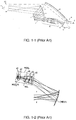
- the prior art described in Ref [8], shown in FIG. 1-1 uses a concave HOE reflector (11 in FIG 1-1 ) as a combiner and collimator to minimize collimation optics and reduce the HUD system volumetric aspect.
- the resultant HUD system needs complicated tilted relay optics (10 in FIG. 1-1 ) to compensate aberration and deliver an intermediate image.
- this HUD system works only for a narrow spectrum.
- the prior art described in Ref [9], shown in FIG. 1-2 uses a relay optics (REL) module to deliver an intermediate image at the focal plane of convergent combiner (CMB) mirror (CMB in FIG. 1-2 ) and defines the system pupil.
- the CMB mirror collimates the intermediate image and images the system pupil onto the viewer's eye to facilitate viewing.
- This pupil imaging HUD approach always involves a complicated REL module for packaging and aberration compensation.
- the prior art described in Ref [10], shown in FIG. 1-3 uses a projection lens (3) to project an intermediate image on a diffusive surface (51 in FIG. 1-3 ) as an image source and a semi-transparent collimating mirror (7 in FIG. 1-3 ).
- the collimating mirror forms an image at infinity and the aperture of the collimation optics is defined by the angular width of the diffuser.
- the prior art described in Ref [11], shown in FIG. 1-4 uses an image forming source comprised of two liquid crystal display (LCD) panels (23 in FIG. 1-4 ) to form an intermediate image on a diffusive screen (5 in FIG. 1-4 ) which is placed at the focal plane of the collimation optics module (1 in FIG. 1-4 ).
- the main purpose of the two LCD panels in the image forming source is to achieve sufficient brightness for viewability of the formed image.
- the two LCD panels in the image forming source are configured to either form two contiguous side by side images at the diffusive screen or overlap two images shifted from each other horizontally and vertically by a half pixel at the diffusive screen.
- the prior art described in Ref [12] uses a pair of reflective holographic optical elements (HOE) to achieve holographic dispersion correction and to project a virtual image of a broadband display source within the observer's field of view.
- the prior art described in Ref [13] also uses a pair of holographic optical elements (HOE); one transmissive and another that is reflective to project an image onto the vehicle windshield.
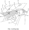
- FIG. 1-5 uses an image projector (14 in FIG. 1-5 ) mounted on the topside of the vehicle windshield configured to project an image onto the vehicle dashboard equipped with a faceted reflective surface (18 in FIG. 1-5 ) with the latter being configured to reflect the image from the image projector onto the windshield of the vehicle.
- the vehicle windshield surface is oriented to reflect the image from the dashboard faceted reflective surface toward the viewer.
- the prior art Ref [19] describes a head-up display device for a vehicle having a number of display units which display different route guidance pictures.
- the light radiated from the display units is led by a corresponding optical system comprising a curved surface mirror.
- the radiated light is led to a translucent image display part positioned in front of the driver.
- the positions of the respective displayed pictures on the display part are separated.
- the image of the right display unit is displayed on the right side and the image of the left display unit is displayed on the left side of the display part.
- SSL solid state light
- LED light emitting diode
- LD laser diode
- the size of the pixels comprising the emissive array of such imager devices would typically be in the range of approximately 5-20 microns with the typical emissive surface area of the device being in the range of approximately 15-150 square millimeters.
- the pixels within the emissive micro-scale pixel array device are individually addressable spatially, chromatically and temporally, typically through the drive circuitry of its CMOS chip.
- the brightness of the light generate by such imager devices can reach multiple 100,000 cd/m2 at reasonably low power consumption.
- QPI imagers see Ref. [1-7]
- QPI imagers are merely an example of the types of devices that may be used in the present invention.
- QPI is a trade mark of Ostendo Technologies, Inc.
- any references to a QPI imager is to be understood to be for purposes of specificity in the embodiments disclosed as one specific example of a solid state emissive pixel array imager that may be used, and not for the purpose of any limitation of the invention.
- the present invention combines the emissive micro pixel array device unique capabilities of such imagers with a novel split exit pupil HUD system architecture in order to realize a low-cost and small volume modular HUD (MHUD) system that can be readily used in applications where the cost and volumetric constraints are paramount, such as for example an automotive HUD.
- MHUD low-cost and small volume modular HUD
- the combination of the emissive high brightness micro emitter pixel array of imagers such as the QPI imagers and the split exit pupil HUD architecture of this invention can enable HUD systems that operate effectively in the high brightness ambient sunlight yet are volumetrically small enough to fit behind the dashboard or instrument panel of a wide range of vehicle sizes and types.
- the word vehicle as used herein is used in the most general sense, and includes any means in or by which someone travels, including but not necessarily limited to travel on land, water, underwater and through the air.
- the low cost and modularity of the split exit pupil HUD architecture enabled by the such imagers enables a modular HUD system that can be tailored to fit the volumetric constraints of a wide range of vehicles.
- the virtues of the split exit pupil HUD system will become more apparent from the detailed description provided herein within the context of the embodiments described in the following paragraphs.
- FIG. 2 illustrates the design concept of the modular HUD (MHUD) system 200 of one embodiment of this invention.
- the MHUD system 200 of the invention is comprised of the MHUD assembly 210 which in turn is comprised of multiplicity of the modules 215 assembled together to form the MHUD 210 whereby each module 215 is comprised of a single imager (such as a QPI imager) with associated optics 220 and a concave mirror 230.
- a single imager such as a QPI imager
- each single imager with associated optics 220 is collimated, magnified and reflected by its associated concave mirror 230, then partially reflected off the vehicle windshield 240 to form the virtual image 260 which is viewable within the eye-box segment 255 located at the nominal head position of the vehicle's driver (operator).
- each of the modules 215 of the MHUD assembly 210 is disposed to form the same virtual image 260 at any one time and at the same location from the vehicle windshield 240, but each at its corresponding eye-box segment 255, such that the multiplicity of modules 215 of the MHUD assembly 210 collectively form the collective eye-box 250 of the MHUD system 200.
- the virtual image 260 could be partially viewable from each of the eye-box segments 255 but fully viewable in the collective eye-box 250. Accordingly, the overall size of the MHUD system 200 eye-box segment 255 can be tailored by selecting the appropriate number of the modules 215 comprising the MHUD assembly 210. While each of the modules 215 of the MHUD assembly 210 is disposed to form the same virtual image 260 at any one time, those images of course will change with time, and may change slowly, as will for example a fuel gauge image, or may change more rapidly, such as in the display of a GPS navigation system display image, though the MHUD system 200 of the present invention may operate at frequencies at least up to a typical video rate if the image data is available at such a rate.
- the eye-box segments 255 of the modules 215 of the MHUD assembly 210 are each located at the exit pupil of the light ray bundle reflected by their corresponding concave mirror 230.
- the collective eye-box 250 of the MHUD system 200 is in effect a split exit pupil eye-box that is formed by the overlap of the eye-box segments 255 of the modules 215 of the MHUD assembly 210.
- This split exit pupil design method of the MHUD system 200 of this invention is further explained in more detail in the following paragraphs.
- the MHUD assembly 210 is comprised of a multiplicity of the modules 215 assembled together to form the MHUD assembly 210 whereby each module 215 is comprised of a QPI imager with associated optics 220 and a concave mirror 230.
- the design method of the MHUD assembly 210 of the MHUD system 200 of this embodiment of the invention and its respective modules 215 are described in more detail in the following paragraph preceded by an explanation of the pertinent advantages and related design parameters tradeoff of the MHUD system 200 of this invention.
- the image generated by a HUD system is typically superimposed on the natural scene to make the viewer operating the vehicle be visually aware of the vehicle operating parameters and to also provide critical information, such as navigation for example, without requiring the driver to take their sight and attention away from the road or the external surroundings of the vehicle.
- the important parameters to consider in the design of a HUD system include; the target size of the collective eye-box, the desired field of view (FOV), the formed image size, the image resolution and the system volumetric constraints. The relationships among these design parameters and constraints are illustrated in FIG. 3 .
- a reduction of MHUD system 200 imager 220 size would lead to a smaller effective focal length (EFL), which is the characteristic optical track length of the system and generally contributes to the reduction of system volume.
- EDL effective focal length
- the reduction of imager aperture size will lead to a lower system F/# accompanied by an increase of optical complexity. This generally results in larger system volume.
- the size of the eye-box segment 255 for each module 215 is scaled along with the imager 220 size to avoid the increase of optical complexity. This leads to the scaling of the volume of each of the modules 215 by the imager 220 size ratio.
- a multiplicity of modules 215 would be combined to form a MHUD assembly 210 that can provide an arbitrary sized collective eye-box 250.
- This novel multi segments eye-box design concept of the MHUD system 200 of this invention is realized by splitting the exit pupil of the system formed at the viewer's eye-box into multiple segments, each corresponding with one of the eye-box segments 255 comprising the collective eye-box 250 of the MHUD system 200 of this invention.
- This split exit pupil design method of the MHUD system 200 of this invention would achieve smaller overall volumetric aspects than a prior art HUD system providing the same size eye-box. This would lead to a reduction in the overall HUD volume, complexity and cost.
- Other advantages of split exit pupil design method of the MHUD system 200 of this invention are described in the following discussion.
- each module is emitting the same image at any one time, so a vehicle operator will see the same virtual image at the same position, independent of which eye-box segment 255 or eye-box segments 255 the operator views.
- the primary contributor to the volume of prior art HUD systems that uses a mirror reflector Ref [8-10] has been identified as the concave mirror.
- the size of the image source would also be proportionally large, which dictates the use of either a large size imager, such as an LCD panel, or forming a large size intermediate image that is projected on a diffusive screen, which adds even more volume for incorporating the projector imager and its associated projection optics.
- the MHUD system 200 of this invention achieves substantially smaller volumetric aspects than prior art HUD systems that use a single concave mirror as the main reflector by using the MHUD assembly 210 that is comprised of the multiple modules 215 each using a smaller size concave mirror 230 that are assembled together to form the overall reflector 235 of the MHUD assembly 210, which is much smaller in size and achieves a much smaller optical track length.
- the MHUD assembly 210 using the smaller aperture size imagers 220 enables the use of smaller aperture size concave mirrors 230 with smaller optical track length which result in the substantially smaller volume and volumetrically efficient MHUD system 200 of this invention.
- FIG. 4 illustrates the optical design aspects and ray trace diagram of the module 215 comprising the MHUD assembly 210.
- the module 215 of a preferred embodiment is comprised of one QPI imager together with its associated optics 220 and the concave mirror 230.
- the optics 420 associated with the QPI imager 410 is shown as a separate lens optical element, in an alternate embodiment of this invention the QPI imager associated optics 420 would be attached directly on top of the emissive surface of the QPI imager 410 to form the QPI imager assembly 220.
- the reflective concave mirror 230 magnifies and collimates the image generated by its corresponding QPI imager (or other imager) 220 to form one eye-box segment 255 of collective eye-box 250, while the optical element 420 associated with the QPI imager 410 in FIG. 4 balances the off-axis distortion and tilting aberrations arising from the reflective concave mirrors 230.
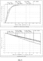
- FIG. 5 illustrates the optical performance of the module 215 of the MHUD assembly 210.
- the role of the optical element 420 associated with the QPI device 410 is to balance the off-axis distortion and tilting aberrations arising from the reflective concave mirrors 230 in order to minimize the image swimming effect while maintaining the modulation transfer function (MTF) sufficiently high.
- the image swimming effect is typically caused by variations in the direction of the light entering the viewer's pupil due to the optical distortion caused by the mirror aberrations and would result in a perceived false motion of the virtual image (known as "swimming effect") as the viewer's head moves (or gazes) about in the HUD system eye-box Ref [16].
- Minimizing the swimming effect in binocular optical systems such as HUD is very important, as in extreme cases excessive swimming effect in the virtual image could lead to motion sickness, vertigos or nauseas. These adverse effects are caused by conflict between vestibular and oculo-motor aspects of the human visual and perception systems, Ref [16,17].
- Another advantage of the split exit pupil method of the MHUD system 200 of this invention is that it achieves a substantially reduced swimming effect when compared to prior art HUD systems that use a single mirror with a larger optical aperture.
- the aberrations of the smaller optical aperture of the reflective concave mirrors 230 would typically be much smaller than the aberrations of the relatively larger optical aperture reflective mirrors used in prior art single mirror HUD systems. Since the swimming effect is directly proportional with the magnitude of the optical distortion (or ray direction deviation) caused by the aberrations arising from the HUD reflective mirror, the multiplicity of smaller optical aperture concave mirrors 230 of the MHUD system 200 of this invention would tend to achieve a substantially smaller swimming effect when compared with prior art HUD systems.
- the angular overlap between the eye-box segments 255 of the MHUD modules 215 would typically cause the perception of any point in the virtual image 260 to incorporate optical contributions from the multiple MHUD modules 215.
- the optical distortions (or ray direction deviation) caused by the aberrations of the individual concave mirrors 230 of the multiple MHUD modules 215 would tend to be averaged at any point in the virtual image 260, consequently causing a reduction in the overall swimming effect perceived by the viewer of the MHUD system 200.
- the imagers 220 of the MHUD assembly 210 would have a resolution that is higher than what the human visual system (HVS) can resolve, with the added resolution being dedicated to a digital image warping pre-compensation of the residual optical distortion caused by the aberrations arising from the concave mirrors 230.
- the virtual image would be formed at a distance of approximately 2.5m.
- the QPI imagers 220 used in the MHUD assembly 210 can provide a much higher resolution than this limit, for example 640x360 resolution or even 1280x720 with the same size optical aperture.
- the QPI imagers 220 providing a higher resolution with the same size optical aperture enables the use of concave mirrors 230 with the same size optical aperture, thus maintaining the volumetric advantage of the MHUD assembly 200.
- the added resolution of QPI imagers 220 allows the use of digital image warping pre-compensation that virtually eliminates the optical distortion arising from the concave mirrors 230 aberration and the resultant swimming effect while maintaining the maximum achievable resolution at the virtual image 260 and the same volumetric advantages.
- Each of the reflective concave mirrors 230 can be either aspheric or free-form whereby the aspherical or free-form factor of the concave mirror is selected to minimize the optical aberrations of the concave mirror 230, and if necessary, the curvature of the windshield. It should be noted that the position of each of the QPI imagers 220 is axially symmetric relative to their associated concave mirror 230 to ensure balanced (somewhat equal) aberration at adjacent edges of any two of the concave mirrors 230. This is an important design aspect of the MHUD system 200 of this invention because it ensures uniform viewing transition of the virtual image 260 between the multiple eye-box segments 255 of the collective eye-box 250 of the MHUD system 200.
- FIG. 6 illustrates a multi view perspective of the MHUD assembly 210.
- the MHUD assembly 210 is comprised of three reflective concave mirrors 230 assembled together within the enclosure 600.
- the three concave mirrors 230 can be either fabricated separately then fitted together within the enclosure 600 or can be fabricated as a single part then fitted within the enclosure 600.
- the three concave mirrors 230, whether assembled separately or as a single optical part, would be fabricated using embossed polycarbonate plastic with the optical surface being subsequently coated with a thin layer of reflective metal, such as silver or aluminum, using sputter techniques. As illustrated in FIG.
- the back sidewall of the enclosure is comprised of three separate sections 610, each incorporating an optical window 615 which, when the back sidewall sections 610 are assembled together each with its respective concave mirror 230, would be aligned with the optical axis of their respective concave mirror 230.
- the top edge 617 of each of the back sidewall sections 610 is angled toward the concave mirror 230 to allow the imagers 220, which would be mounted on the angled edge surface 617 of the back sidewall sections 610, to be aligned with the optical axis of their respective concave mirror 230.
- the back sidewall sections 610 would be assembled together on one side of the back plate 630 with the control and interface electronics (printed circuit board) 620 of the MHUD assembly 210 mounted on the opposite side of the back plate 630.
- the back plate 630 also incorporates thermal cooling fins to dissipate the heat generated by the imagers 220 and the interface electronics element 620 of the MHUD assembly 210.
- each of the imagers 220 would typically be mounted on a flexible electrical board 618 that connects the imagers 220 to the control and interface electronics 620.
- the centers of the interface edges of the each pair of the concave mirrors 230 and the back sidewall sections 610 incorporate the photo detectors (PD) 640, typically photo-diodes, each positioned and oriented to detect the light emitted from the imagers 220 onto their respective concave mirror 230. Typically three photo-diodes would be used in each module, one for each color of light emitted.
- the output of the photo detectors (PD) 640 is connected to the control and interface electronics 620 of the MHUD assembly 210 and is used as input to the uniformity control loop (described in the discussion below), implemented within the hardware and software design elements of the interface electronics element 620.
- the uniformity control loop described in the discussion below
- the output of the ambient light photo detector sensor 660 is typically an integral part of most vehicles' dashboard brightness control.
- the control and interface electronics 620 of the MHUD assembly 210 incorporates the hardware and software design functional elements illustrated in the block diagram of FIG. 7 , which include the MHUD interface function 710, the control function 720 and the uniformity loop function 730.
- the MHUD interface function 710 of the control and interface electronics 620 of the MHUD assembly 210 which is typically implemented in a combination of hardware and software, receives the image input 715 from the vehicle's Driver Assistance System (DAS) and incorporates into the image the color and brightness corrections 735 provided by the control function 720, then provides image inputs 744, 745 and 746 to the imagers 220 of the MHUD assembly 210.
- DAS Driver Assistance System
- the MHUD interface function 710 incorporates each imager 220 specific color and brightness corrections in their respective image inputs 744, 745 and 746 based on the color and brightness corrections 735 received from the control function 720.
- the uniformity loop function 730 of the control and interface electronics 620 receives the input signals 754, 755 and 756 from the photo detectors (PD) 640 of each of the modules 215 of the MHUD assembly 210, computes the color and brightness associated with each of the modules 215 of the MHUD assembly 210 then calculates the color and brightness corrections required to make the color and brightness become more uniform across the multiple segments 255 of the collective eye-box 250. This would be accomplished with the aide of an initial calibration look-up table that would be performed and stored in the memory of the control and interface electronics 620 when the MHUD assembly 210 is originally assembled.
- the color and brightness corrections calculated by the uniformity loop function 730 are then provided to the control function 720 which combines these corrections with input received from the ambient light sensor 650 and the external color and brightness adjustment input command 725 to generate the color and brightness corrections 735 which then are incorporated into the image data by the MHUD interface function 710 before the corrected image data is provided as the image inputs 744, 745 and 746 to the imagers 220.
- the control function 720 would adjust the brightness of the virtual image of the heads-up display in proportion with or in relation to the vehicle external light brightness.
- image data as used herein means image information in any form whatsoever, whether as received as an input to the heads-up display, as provided to the imagers or as in any other form.
- one embodiment of the MHUD system 200 uses imagers 220 with higher resolution than the maximum HVS resolvable resolution at the virtual image 260 and incorporates means to eliminate or substantially reduce optical distortion and the swimming effect it causes by digitally warping the image input to the imagers 220.
- the MHUD interface function 710 of the MHUD assembly 210 of the MHUD system 200 of that embodiment would also incorporate a multiplicity of look up tables each incorporating data that identifies the digital image warping parameters required to pre-compensate for the residual optical distortion of each of the concave mirrors 230.
- the MHUD interface function 710 uses these parameters to warp the digital image input of each of the imagers 220 in such a way that the image data input to each of the imagers 220 pre-compensates for their corresponding concave mirror 230 residual distortion.
- the digital image warping parameters incorporated in the look up tables of the MHUD interface function 710 would be preliminarily generated from the optical design simulation of the MHUD assembly 210, then augmented with optical test data that is based on measurements of the residual optical distortion of each module 215 after the digital image warping pre-compensation is applied by the MHUD interface function 710.
- the resultant digitally warped image data is then combined with the color and brightness corrections 735 provided by the control function 720, then the color and brightness corrected and distortion pre-compensated image data is provided as the image inputs 744, 745 and 746 to the imagers 220 of the MHUD assembly 210.
- the residual optical distortion caused by the concave mirrors 230 and its resultant swimming effect would be substantially reduced or eliminated altogether, thus making it possible to realize a distortion-free MHUD system 200.
- the top side of the MHUD assembly 210 is a glass cover 430, which would function as the optical interface window of the MHUD assembly 210 at the top surface of the vehicle dashboard and would also function as a filter that would attenuate the sunlight infrared emission to prevent sunlight thermal loading at the imagers 220.
- the glass used should be selected to also be substantially transparent to the wave lengths of the light of interest.
- the design method of the MHUD assembly 210 leverages the characteristics of the human visual system (HVS) to simplify the design implementation and assembly tolerances of the MHUD assembly 210.
- HVS human visual system
- the eye pupil being approximately 5 mm in diameter (3-5 mm in daytime and 4-9 mm in night time) and resultant lateral acuity in viewing the virtual image 260 would allow an indiscernibly small gap between the MHUD assembly 210 concave mirrors 230 that can reach as much as 1 mm in width.
- the eye angular difference accommodation limit of approximately 0.5 degree would allow a small angular tilt between the MHUD assembly 210 concave mirrors 230 that can reach approximately 0.15 degree.
- tilt and gap allowances set forth a remarkably relaxed mechanical alignment tolerance requirement for the MHUD assembly 210 concave mirrors 230 and therefore enable a very cost effective manufacturing and assembly approach for the MHUD assembly 210. Any further tilt and/or alignment requirements man be easily accommodated, normally in software.
- FIG. 8 illustrates the novel split eye-box design method of the MHUD system 200 of this invention.
- the illustration of FIG. 8 is meant to show the relationship between collective eye-box 250 and the virtual image 260 of the MHUD system 200.
- FIG. 8 also illustrates an example object 810, the arrow shown on the virtual image 260, displayed by the MHUD system 200.
- each of the eye-box segments 255 would typically be positioned at the exit pupil of its respective module 215. As a result the image information presented to the viewer's eyes within each of the eye-box segments 255 would be in the angular space.
- the virtual image 260 arrow object 810 presented to the viewer within each of the eye-box segments 255 separately would typically be fully visible to the viewer when the viewer's head is positioned within the central region of the respective eye-box segment 255, but the tip or tail ends of the arrow object 810 of the virtual image 260 would gradually vignette (or fade away) when the viewer's head is moved to the right side or left side of the eye-box segment 255, respectively.
- the eye-box segments 255 of the modules 215 would be made to overlap, as illustrated in FIG.
- the collective eye-box 250 of the MHUD system 200 is formed by the overlap of the exit pupil areas forming the eye-box segments 255 of the multiplicity of modules 215, thus making the image information presented to the viewer's eyes within the collective eye-box 250 be an angularly multiplexed view of the virtual image 260 extending over the combined angular field of view of the MHUD modules 215. As illustrated in FIG.
- the arrow object 810 of the virtual image 260 would become fully visible (or viewable) within the overlap area of the eye-box segments 255 defining the collective eye-box 250 of the MHUD system 200 with the arrow object 810 of the virtual image 260 gradually vignetting (or fading away) when the viewer's head is moved to the right side or left side of the peripheral regions of the collective eye-box 250, respectively.
- the size of overlap between the eye-box segments 255 of the modules 215 is dependent upon their angular vignetting profiles, 820 in FIG. 8 , and would determine the ultimate size of the collective eye-box 250 of the MHUD system 200.
- the latter is defined as the collective eye-box 250 area boundaries or dimensions within which the virtual image 260 is fully visible (or viewable) at the desired brightness uniformity.
- FIG. 8 also illustrates the resultant angular vignetting profile shield of the MHUD assembly 210 across the overall area of the overlapping eye-box segments 255 of the modules 215. As illustrated in FIG.
- the brightness of the virtual image 260 that would be perceived by the viewer would include brightness contributions of ⁇ R , ⁇ C , and ⁇ L (left, center and right) from each of the modules 215; respectively.
- the criterion for defining the boundaries of the collective eye-box 250 would be the area A of the overlap of the eye-box segments 255 within which the virtual image 260 brightness is uniform within a given threshold ⁇ (for example, less than 25%) across the selected region; i.e., Var A ( ⁇ R + ⁇ C + ⁇ L ) ⁇ ⁇ , the desired uniformity threshold.
- the perceived brightness across the virtual image 260 would typically include a contribution of at least 50% from one of the modules 215. Meaning that anywhere within the boundaries of the collective eye-box 250 defined by the stated criterion, each of the modules 215 would contribute at least 50% of the perceived brightness of the virtual image 260.
- the desired brightness uniformity of the virtual image 260 would become the criterion that defines the size of the collective eye-box 250.
- the arrow object 810 of the virtual image would gradually vignette or fade away as the viewer's head moves into these regions; respectively.
- the addition of a module 215 to either the right or left sides of the MHUD assembly 210, illustrated in FIG. 6 would extend the lateral width of the collective eye-box 250 of the MHUD system 200, as defined by the design criterion defined earlier, to the right or left sides; respectively, where the arrow object 810 of the virtual image 260 would become fully visible at a desired brightness uniformity.
- any arbitrary size collective eye-box 250 with any design selected width and height dimensions can be realized by adding more of the modules 215 into the MHUD assembly 210.
- the split exit pupil modular design method of the MHUD system 200 of this invention enables the use of a multiplicity of QPI imagers 220 and concave mirrors 230, each with relatively smaller apertures and each achieving a short optical track length to replace the much longer optical length of the larger image source and the single mirror used in prior art HUD systems.
- the smaller apertures imagers 220 and concave mirrors 230 of the MHUD modules 210 collectively enable a substantially smaller volumetric aspect than can be achieved by prior art HUD systems that use a larger single image source and a single mirror to achieve the same size eye-box.
- the size of the achieved collective eye-box 250 of the MHUD system 200 can be tailored by using the appropriate number of modules 215 basic design elements.
- the volumetric aspects of the MHUD system 200 can be made to match the volume available in the vehicle dashboard area while achieving a larger size collective eye-box 250 than would be achieved by a prior art HUD system that can fit in the same available volume.
- FIG. 9 illustrates the volume of the MHUD assembly 210 design example illustrated in FIG. 6 installed in the dashboard of a sub-compact automobile.
- the volumetrically efficient design of the MHUD system 200 of this invention enables the addition of HUD capabilities in an automobile with very constrained dashboard volume in which prior art HUD systems would simply not fit.
- FIG. 10 illustrates the ray path of the MHUD system 200.
- the three QPI imagers 220 comprising the MHUD assembly 210 would each generate the same image at the same resolution (for example 640x360 pixels) with the three images, and after being reflected by their three respective concave mirrors 230, would angularly address the entire 120x60 mm collective eye-box 250 of the earlier described design example and would collectively provide 640x360 spatial resolution across the 125x225 mm virtual image 260 of the earlier described design example.
- FIG. 10 illustrates a design requirement to generate 10,000 cd/m2 of brightness at the virtual image 260.
- each of the three QPI imagers 220 would generate approximately 25,000 cd/m2 of brightness.
- the three QPI imagers 220 plus the control and interface electronics 620 of the MHUD assembly 210 would collectively consume approximately 2 W to generate 25,000 cd/m2 of brightness, which is approximately 25% of the power consumption of a prior art HUD system.
- the encircled energy plot of FIG. 5 shows the geometrical blur radius of the collimated light beam from the concave mirror 230 optical aperture of 180 micron in size.
- the 180 micron blur size indicated in the encircled energy plot of FIG. 5 gives each of the modules 215 an angular spread of 0.143 deg for a light beam originating at a pixel of the imager 220 and collimated by its corresponding concave mirror 230.
- the swimming effect associated with an angular spread of 0.143 deg over the full beam width from a pixel while resolution (MTF) is decided by the effective beam width sampled by eye pupil size.
- the MTF plot of FIG. 5 shows the MTF of each of the modules 215 calculated for a typical eye pupil aperture of 4mm diameter. The smaller this angular spread angle, the smaller the swimming radius at the virtual image 260. For a virtual image 260 viewed 2.5m from the collective eye-box 250 of the MHUD system 200, the corresponding swimming radius for the MHUD system 200 design example would be 6.2mm.
- a prior art HUD system that uses a single mirror and having an optical aperture size equal to the full aperture size of the MHUD assembly 210 design example would have an optical aperture that is approximately 2.4x larger than the optical aperture of the module 215. Since the aberration blur size is directly proportional to the aperture size raised to the third power Ref [18], the prior art single mirror HUD system having an optical aperture size equal to the full aperture size of the MHUD assembly 210 design example would have a corresponding swimming radius approximately 14.3mm if the 5 th order aberration happens to compensate for the large 3 rd order aberration, which cannot be achieved purposefully by design, otherwise the prior art single mirror HUD system would typically have a corresponding swimming radius of approximately 39.7mm, which is 6.2x larger than the swimming radius achieved by the design example of the MHUD system 200. It should also be mentioned that with the aberration pre-compensation method described earlier, the MHUD system 200 swimming radius can be substantially reduced below the stated values of this design example or even eliminated altogether.
- FIG. 10 also illustrates the ray path of the MHUD system 200 with the sunlight loading included.
- the reverse optical path of the sunlight that strikes the windshield of the vehicle would reach the collective eye-box 250 area possibly causing a glare in the virtual image 260.
- the amount of sunlight rays that could reach the collective eye-box 250 will be much less in comparison to prior art HUD systems.
- the windshield 240 optical transmission is 80%, the light rays from the sun will be attenuated by the windshield 240 to at most 80% of its brightness.
- the sun rays transmitted through the windshield 240 and reflected by one of the concave mirrors 230 toward its corresponding imager 220 would be further attenuated by the anti-reflective (AR) coating on the optical aperture of the imager 220 to at most 5% of its brightness before it is reflected back toward the concave mirrors 230 assembly.
- this reverse path sunlight would then be further attenuated to at most by 20% of its brightness when it is reflected by windshield 240 toward the collective eye-box 250.
- the imager 220 and concave mirror 230 of each of the modules 215 contributes at most 50% to the brightness of the virtual image 260
- the sunlight glare reflected from the modules 215 stricken by the sunlight would appear further attenuated by 50% at the virtual image 260. Therefore, based on this path attenuation analysis, the sunlight that would reach the collective eye-box 250 would be attenuated to at most to 0.4% (much less than 1%) of its brightness.
- the MHUD system 200 With the MHUD system 200 being able to generate more than 10,000 cd/m2 of brightness and 0.4% sunlight glare at the virtual image 260, the MHUD system 200 can tolerate a sunlight brightness of more than 250,000 cd/m2, which is equivalent to a unified glare rating (UGR) (or glare to image intensity ratio) of approximately 28dB.
- ULR unified glare rating
- the glass cover 430 would be infrared absorbing, but transparent to light of the wavelengths used in the heads-up display of the present invention to prevent the sun loading heat from being concentrated by the concave mirror 230 assembly back to the imagers 220.
- modules were disposed side by side to provide overlapping eye-box segments to provide a wider collective eye-box 250 than the eye-box segments 255 themselves.
- the modules may be disposed so that the eye-box segments of modules 215 are also stacked to provide a taller collective eye-box 250, again all modules displaying the same virtual image at the same position in front of the vehicle.
- the stacking to provide a taller collective eye-box 250 is in general not a stacking of modules, but rather because of the slope of the typical windshield, the stacking of the eye-box segments may be accomplished by simply using a larger, substantially horizontal area of the dashboard for the additional modules. Also while it was previously stated that "As illustrated in FIG.
- the image emitted from each single imager with associated optics 220 is collimated, magnified and reflected by its associated concave mirror 230, then partially reflected off the vehicle windshield 240 to form the virtual image 260 which is viewable within the eye-box segment 255 located at the nominal head position of the vehicle's driver (operator)", in any embodiment, the extent of collimation achieved by the concave mirror will necessarily be less than perfect, and may be intentionally set to limit how far ahead of the vehicle the virtual image will be formed.
- the concave mirrors may in fact be purposely designed to distort the collimation to offset any following sources of aberrations, the curvature of a windshield, if any, being the most obvious example.
- off-axis distortion and tilting aberrations and color and brightness corrections can be made in the control and interface electronics 620 of the MHUD assembly 210 of Fig. 2 (see also Fig. 6 ).
- lateral position correction of each image or image segment from each module 215 may also be made in the control and interface electronics 620 (or mechanically) so that double images or double image portions are not displayed.
- "brightness corrections" have at least two primary aspects. The first and most obvious is the correction of brightness variations, module to module, so that an image brightness (and color) from different modules will not be different.
- Table 1 below presents the salient performance characteristics of the QPI imager based MHUD system 200 of certain embodiments of the invention illustrating their performance advantages in comparison to prior art HUD system that uses a single larger mirror and a single larger image source.
- the split exit pupil MHUD system of this invention out performs prior art HUD systems by multiple factors in every performance category.
- the MHUD systems 200 of this invention are expected to be much more cost effective than prior art with comparable eye-box size.
- Table 1 Performance Comparison Parameter Prior Art HUD * QPI Imager Based MHUD Color Reproduction (Ratio of NTSC) 80% 140% Programmable Virtual Image Intensity 6,000 cd/m 2 > 10,000 cd/m 2 Contrast Ratio 400:1 > 100,000:1 Power Consumption (Imager + Drive Electronics) > 8 W ⁇ 2 W Relative Size (HUD Assembly) 100% ⁇ 25% Aberration Induced swimming Effect 100% ⁇ 16% * Prior Art HUD based on using a high brightness LCD panel as image source
Landscapes
- Physics & Mathematics (AREA)
- General Physics & Mathematics (AREA)
- Engineering & Computer Science (AREA)
- Optics & Photonics (AREA)
- Theoretical Computer Science (AREA)
- Computer Hardware Design (AREA)
- Instrument Panels (AREA)
Claims (43)
- Ein Head-up-Display für ein Fahrzeug, aufweisend:eine Vielzahl von Modulen (215), wobei jedes Modul (215) aufweist;einen Festkörper-Leuchtpixel-Array-Bilderzeuger (410); undeinen konkaven Spiegel (230), der so angeordnet ist, dass er ein von dem Festkörper-Leuchtpixel-Array-Bilderzeuger (410) erzeugtes Bild kollimiert, vergrößert und in Richtung einer Fahrzeugwindschutzscheibe (240) reflektiert, um ein virtuelles Abbild (260) zu bilden, das innerhalb eines Eyebox-Segments (255) sichtbar ist;wobei die Vielzahl von Modulen (215) so angeordnet ist, dass sich die Eyebox-Segmente (255) verbinden, so dass das Head-up-Display eine kollektive Eyebox (250) hat, welche größer ist als das Eyebox-Segment (255) jedes Moduls (215), wobei die kollektive Eyebox (250) an einer nominellen Kopfposition eines Fahrers des Fahrzeugs angeordnet ist;wobei jedes Modul (215) so konfiguriert und positioniert ist, dass das jeweilige virtuelle Abbild des Bildes sich an der gleichen Position gegenüber der Fahrzeugwindschutzscheibe (240) befindet, und wobei jedes Modul (215) mit seinem jeweiligen Eyebox-Segment (255) an einer Austrittspupille des zugehörigen Moduls derart positioniert ist, dass sich benachbarte Eyebox-Segmente (255) der Vielzahl von Modulen (255) überlappen und verbinden, so dass eine Eyebox mit aufgeteilter Austrittspupille gebildet ist, wodurch die einem Fahrer des Fahrzeugs innerhalb der kollektiven Eyebox (250) präsentierten Bildinformationen eine bezüglich des Winkels gemultiplexte Ansicht des virtuellen Abbilds sind, die sich über einen kollektiven Sichtwinkel erstreckt.
- Das Head-up-Display nach Anspruch 1, wobei die Überlappung der Exebox-Segmente (255) der Vielzahl von Modulen (215) eine gemeinsame Eyebox (250) mit aufgeteilter Austrittspupille bildet.
- Das Head-up-Display nach Anspruch 1, wobei die Größe der Eyebox-Segmente (255) jedes Moduls (215) und die Anzahl der Module (215) in dem Head-up-Display so ausgewählt sind, dass eine Größe der gemeinsamen Eyebox zur Verfügung gestellt wird, die einem Bereich der Kopfpositionen des Fahrers angepasst ist.
- Das Head-up-Display nach Anspruch 1, wobei die Eyebox des Head-up-Displays mit aufgeteilter Austrittspupille ein Head-up-Display mit einer Eyebox maßgeschneiderter Größe und volumetrischen Aspekten ermöglicht, um zu einem weiten Bereich von Fahrzeuganforderungen zu passen, während die gleichen Head-up-Display-Module (215) verwendet werden.
- Das Head-up-Display nach Anspruch 1, wobei die gemeinsame Eyebox (250) eine Größe aufweist, die in ihrer Breite und/oder in ihrer Höhe erweiterbar ist, indem ein oder mehrere zusätzliche Module (215) hinzugefügt werden.
- Das Head-up-Display nach Anspruch 1, wobei die Begrenzungen der gemeinsamen Eyebox (250) Bereiche der Überlappung von Eyebox-Segmenten (255) sind, innerhalb welcher die Helligkeit des virtuellen Abbilds (260) innerhalb eines gegebenen Schwellwerts über die gemeinsame Eyebox (250) gleichförmig ist.
- Das Head-up-Display nach Anspruch 6, wobei:
die Überlappung zwischen den Eyebox-Segmenten (255) bewirkt, dass an der Wahrnehmung irgendeines Punkts in dem virtuellen Abbild (260) durch den Fahrer optische Beiträge von mehr als einem der Vielzahl von Modulen (215) beteiligt sind, wodurch bewirkt wird, dass optische Verzerrungen oder Strahlrichtungsabweichungen, die durch Aberrationen der einzelnen konkaven Spiegel der Vielzahl von Modulen (215) induziert werden, an jedem Punkt in dem virtuellen Abbild gemittelt werden, wodurch ein etwaiger durch den Fahrer wahrgenommener Verschwimmungseffekt verringert wird. - Das Head-up-Display nach Anspruch 1, wobei die konkaven Spiegel (230) entweder eine asphärische oder eine beliebig geformte reflektierende Oberfläche aufweisen, wobei der asphärische oder beliebige Formfaktor der reflektierenden Oberflächen so ausgewählt ist, dass ihre optischen Abbildungsfehler minimiert werden.
- Das Head-up-Display nach Anspruch 8, wobei die Festkörper-Leuchtpixel-Array-Bilderzeuger (410) jeweils eine zugeordnete Optik (220; 420) enthalten, die eine Off-Axis-Verzerrungs- und Kipp-Abbildungsfehler ausgleichen, die von dem zugehörigen konkaven Spiegel (230) herrühren, wobei die zugehörige Optik (220; 420) entweder ein optisches Element mit separater Linse ist oder direkt auf dem zugehörigen Festkörper-Leuchtpixel-Array-Bilderzeuger befestigt ist.
- Das Head-up-Display nach Anspruch 9, wobei:
die Abbildungsfehler, die durch eine Aperturgröße jedes der Vielzahl von konkaven Spiegeln (230), die asphärischen oder beliebigen Formfaktoren der konkaven Spiegel und die Off-Axis-Verzerrungs- und Kipp-Abbildungsfehler-Ausgleichseffekte der dem Festkörper-Leuchtpixel-Array-Bilderzeuger zugeordneten Optik (420) erzielt werden, gemeinsam die von den konkaven Spiegeln (230) bewirkten optischen Verzerrungen minimieren, wodurch etwaige dem Head-up-Display zugeordnete Verschwimmungseffekte minimiert werden. - Das Head-up-Display nach Anspruch 1, wobei jedes Modul (215) eine optische Aperturgröße und eine Pixelauflösung zur Verfügung stellt, die eine höhere Auflösung bereitstellt, als das menschliche Auge an der Position des virtuellen Abbilds auflösen kann, wobei die zusätzliche Auflösung einem digitalen Image Warping gewidmet ist, um eine restliche optische Verzerrung zu kompensieren, die durch Abbildungsfehler bewirkt wird, welche von den konkaven Spiegeln (215) herrühren, wodurch etwaige von dem Fahrer des Head-up-Displays wahrgenommene Verschwimmungseffekte reduziert werden.
- Das Head-up-Display nach Anspruch 1, ferner aufweisend:eine Baugruppe (210), aufweisend:die Vielzahl von Modulen (215);eine Vielzahl von Fotodetektoren (410); undeine Steuereinrichtung (620);wobei die mehreren Fotodetektoren (640) jeweils innerhalb der Baugruppe (210) so positioniert sind, dass sie das von dem Festkörper-Leuchtpixel-Array-Bilderzeuger (410) eines zugehörigen Moduls (215) emittierte Licht erfassen;wobei die Steuereinrichtung (620) mit einer Quelle von Bilddaten für das anzuzeigende virtuelle Abbild, mit Ausgängen der Fotodetektoren (640) und mit Eingängen der Festkörper-Leuchtpixel-Array-Bilderzeuger (410) gekoppelt ist, wobei die Steuereinrichtung (620) Steuerfunktionen in elektronischer Hardware und/oder Software implementiert, die auf die Ausgangssignale der Fotodetektoren (640) ansprechen, um die Festkörper-Leuchtpixel-Array-Bilderzeuger (410) so anzusteuern, dass eine Farb- und Helligkeitsgleichmäßigkeit über die mehreren Eyebox-Segmente (255) der gemeinsamen Eyebox (250) gesichert wird.
- Das Head-up-Display nach Anspruch 12, wobei die Steuereinrichtung (620) ferner einen Anschluss zum Ankoppeln eines Ausgangs eines Umgebungslichtfotodetektors (650) eines Fahrzeugs aufweist, wie er zum Steuern der Helligkeit einer Armaturentafel des Fahrzeugs verwendet wird.
- Das Head-up-Display nach Anspruch 12, wobei:
die Quelle der Bilddaten ein Fahrer-Assistenzsystem ist und die in elektronischer Hardware und/oder Software in der Steuereinrichtung (620) implementierten Steuerfunktionen einschließen:eine auf die Ausgangssignale der Fotodetektoren (640) ansprechende Gleichförmigkeitsschleifenfunktion (730) zum Berechnen der jeweiligen Farb- und Helligkeitskorrekturen und zum Einkoppeln der Korrekturen in jeden der zugehörigen mehreren Festkörper-Leuchtpixel-Array-Bilderzeuger, um eine Farb- und Helligkeitsgleichförmigkeit über die gemeinsame Eyebox (250) des Head-up-Displays zur Verfügung zu stellen:eine erste Steuerfunktion (720), die die von der Gleichförmigkeitsschleifenfunktion (730) berechneten Farb- und Helligkeitskorrekturen mit einem Eingangssignal kombiniert, das von einem Umgebungslichtfotodetektorsensor (650) eines Fahrzeugs, wie er zum Steuern der Helligkeit einer Fahrzeugarmaturentafel verwendet wird, empfangen werden soll, undeine Schnittstellenfunktion (710), die die Bilddaten (715) von dem Fahrer-Assistenzsystem des Fahrzeugs empfängt, spezielle Farb- und Helligkeitskorrekturen (735), die von der Steuerfunktion (720) zur Verfügung gestellt werden, in die Bilddaten einbringt, die an jeden Festkörper-Leuchtpixel-Array-Bilderzeuger zur Verfügung gestellt werden, undeine zweite Steuerfunktion zum Steuern jedes der mehreren Festkörper-Leuchtpixel-Array-Bilderzeuger durch Bereitstellen von Bilddaten, wie sie für den jeweiligen Festkörper-Leuchtpixel-Array-Bilderzeuger korrigiert worden sind. - Das Head-up-Display nach Anspruch 14, wobei:die Steuereinrichtung (620) einen externen Farb-und-Helligkeits-Anschluss zum Koppeln mit einem externen Farb-und-Helligkeits-Einstell-Eingangssignal aufweist und wobei die Schnittstellenfunktion (710) ferner eine Möglichkeit einschließt, eine externe Farb- und Helligkeitseinstellung zu empfangen und diese sowie spezifische von der Steuerfunktion zur Verfügung gestellte Farb- und Helligkeitskorrekturen in die Bilddaten jedes Festkörper-Leuchtpixel-Array-Bilderzeugers einzubringen; unddie zweite Steuerfunktion so konfiguriert ist, dass sie die mehreren Festkörper-Leuchtpixel-Array-Bilderzeuger steuert, indem Bilddaten zur Verfügung gestellt werden, wie sie für den jeweiligen Festkörper-Leuchtpixel-Array-Bilderzeuger korrigiert und in Übereinstimmung mit der externen Farb- und Helligkeitseinstellung eingestellt worden sind.
- Das Head-up-Display nach Anspruch 14, wobei die Schnittstellenfunktion (710) ferner so konfiguriert ist, dass sie ein digitales Image Warping auszuführt, um eine optische Restverzerrung vorzukompensieren, die durch Abbildungsfehler verursacht wird, die aus den konkaven Spiegeln (230) herrühren, wodurch der von dem Fahrer wahrgenommene Verschwimmungeffekt reduziert wird.
- Das Head-up-Display nach Anspruch 12, wobei die Steuereinrichtung (620) ferner einen Anschluss zum Ankoppeln eines Ausgangs eines Umgebungslichtfotodetektors (650) aufweist, wobei das Ausgangssignal des Umgebungslichtfotodetektors von der Steuereinrichtung verwendet wird, um die Helligkeit der virtuellen Abbildung des Head-up-Displays zu steuern, indem die Helligkeit der Abstrahlungen der mehreren Festkörper-Leuchtpixel-Array-Bilderzeuger in Bezug auf die Helligkeit des Umgebungslichts, wie es von dem Umgebungslichtfotodetektor erfasst worden ist, gesteuert wird.
- Das Head-up-Display nach Anspruch 12, ferner aufweisend eine Glasabdeckung (430), die ein optisches Schnittstellenfenster bildet, wobei die Glasabdeckung so ausgewählt ist, dass sie die Infrarotemission des Sonnenlichts abschwächt, um eine durch das Sonnenlicht bewirkte thermische Aufheizung jedes der mehreren Festkörper-Leuchtpixel-Array-Bilderzeuger zu verringern oder zu vermeiden.
- Das Head-up-Display nach Anspruch 1, wobei jedes der Module einen konkaven Spiegel (230) mit asphärischen oder beliebig geformten reflektierenden Oberflächen aufweist.
- Das Head-up-Display nach Anspruch 19, wobei die Begrenzungen der gemeinsamen Eyebox (250) Bereiche der Überlappung der Eyebox-Segmente (255) sind, innerhalb welcher die Helligkeit des virtuellen Abbilds (260) innerhalb eines gegebenen Schwellwerts über die gemeinsame Eyebox gleichmäßig ist.
- Das Head-up-Display nach Anspruch 19, wobei die gemeinsame Eyebox (250) eine Größe aufweist, die in ihrer Breite und/oder in ihrer Höhe erweiterbar ist, indem ein oder mehrere zusätzliche Module (215) eingeschlossen werden.
- Das Head-up-Display nach Anspruch 19, wobei die Festkörper-Leuchtpixel-Array-Bilderzeuger (410) jeweils eine zugehörige Optik (220) aufweisen, die Off-Axis-Verzerrungs und Kipp-Abbildungsfehler ausgleichen, die aus dem jeweiligen konkaven Spiegel (230) herrühren, wobei die zugehörige Optik (220) entweder ein optisches Element mit separater Linse ist oder direkt auf dem zugehörigen Festkörper-Leuchtpixel-Array-Bilderzeuger befestigt ist.
- Das Head-up-Display nach Anspruch 19, ferner aufweisend:eine Baugruppe (210), aufweisend:die Vielzahl von Modulen (215);eine Vielzahl von Fotodetektoren (640); undeine Steuereinrichtung (620);wobei mehreren Fotodetektoren (640) jeweils innerhalb der Baugruppe (210) so positioniert sind, dass sie das von einem Festkörper-Leuchtpixel-Array-Bilderzeuger (410) eines zugehörigen Moduls (215) emittierte Licht erfassen;wobei die Steuereinrichtung (620) mit einer Quelle von Bilddaten für das anzuzeigende virtuelle Abbild, mit Ausgängen der Fotodetektoren (640) und mit Eingängen der Festkörper-Leuchtpixel-Array-Bilderzeuger gekoppelt ist, wobei die Steuereinrichtung (620) Steuerfunktionen in elektronischer Hardware und/oder Software implementiert, die auf die Ausgangssignale der Fotodetektoren (640) anspricht, um die Festkörper-Leuchtpixel-Array-Bilderzeuger so anzusteuern, dass eine Farb- und Helligkeitsgleichförmigkeit über die mehreren Eyebox-Segmente (255) der gemeinsamen Eyebox (650) gesichert wird.
- Das Head-up-Display nach Anspruch 23, wobei die Steuereinrichtung (620) ferner einen Anschluss zum Koppeln mit einem Ausgang eines Umgebungslichtfotodetektors (650) eines Fahrzeugs, wie er zum Steuern der Helligkeit einer Fahrzeugarmaturentafel verwendet wird, gekoppelt ist.
- Das Head-up-Display nach Anspruch 23, wobei:
die Quelle der Bilddaten ein Fahrer-Assistenzsystem ist und wobei die in elektronischer Hardware und/oder Software in der Steuereinrichtung implementierten Steuerfunktionen einschließen:eine auf die Ausgangssignale der Fotodetektoren (640) ansprechende Gleichförmigkeitsschleifenfunktion (730) zum Berechnen zugehöriger Farb- und Helligkeitskorrekturen und zum Koppeln der Korrekturen mit jedem der zugehörigen mehreren Festkörper-Leuchtpixel-Array-Bilderzeuger (410), die erforderlich sind, um eine Farb- und Helligkeitsgleichförmigkeit über die gemeinsame Eyebox (250) des Head-up-Displays zur Verfügung zu stellen;eine Steuerfunktion (720), die die von der Gleichförmigkeitsschleifenfunktion (730) berechneten Farb- und Helligkeitskorrekturen mit einem Eingangssignal kombiniert, das von einem Umgebungslichtfotodetektorsensor (650) eines Fahrzeugs, wie er zum Steuern der Helligkeit einer Fahrzeugarmaturentafel verwendet wird, empfangen werden soll, undeine Schnittstellenfunktion (710), die die Bilddaten aus dem Fahrer-Assistenzsystem des Fahrzeugs empfängt, in die jedem der Festkörper-Leuchtpixel-Array-Bilderzeuger zur Verfügung gestellten Bilddaten speziell von der Steuerfunktion zur Verfügung gestellte Farb- und Helligkeitskorrekturen einbringt, undeine Steuerfunktion zum Steuern der mehreren Festkörper-Leuchtpixel-Array-Bilderzeuger, indem Bilddaten zur Verfügung gestellt werden, wie sie für den jeweiligen Festkörper-Leuchtpixel-Array-Bilderzeuger korrigiert worden sind. - Das Head-up-Display nach Anspruch 25, wobei:die Steuereinrichtung (620) einen externen Farb- und Helligkeitsanschluss zum Koppeln mit einem externen Farb- und Helligkeitseinstelleingangssignal enthält und wobei die Schnittstellenfunktion (710) ferner eine Fähigkeit einschließt, eine externe Farb- und Helligkeitseinstellung zu empfangen und diese sowie die von der Steuerfunktion zur Verfügung gestellten speziellen Farb- und Helligkeitskorrekturen in die Bilddaten jedes Festkörper-Leuchtpixel-Array-Bilderzeugers einzubringen; unddie Steuerfunktion (720) so konfiguriert ist, dass die mehreren Festkörper-Leuchtpixel-Array-Bilderzeuger gesteuert werden, indem Bilddaten zur Verfügung gestellt werden, wie sie für den jeweiligen Festkörper-Leuchtpixel-Array-Bilderzeuger korrigiert und in Übereinstimmung mit der externen Farb- und Helligkeitseinstellung eingestellt worden sind.
- Das Head-up-Display nach Anspruch 25, wobei die Schnittstellenfunktion ferner so konfiguriert ist, dass sie ein digitales Image Warping ausführt, um eine optische Restverzerrung vorzukompensieren, die durch Abbildungsfehler verursacht ist, die aus den konkaven Spiegeln (230) herrühren, wodurch der von dem Fahrer wahrgenommene Verschwimmungseffekt reduziert wird.
- Das Head-up-Display nach Anspruch 23, wobei die Steuereinrichtung (620) ferner einen Anschluss zum Koppeln mit einem Ausgang eines Umgebungslichtfotodetektors (650) aufweist, wobei das Ausgangssignal des Umgebungslichtfotodetektors (650) von der Steuereinrichtung (620) verwendet wird, um die Helligkeit des virtuellen Abbilds des Head-up-Displays zu steuern, indem die Helligkeit der Abstrahlungen der mehreren Festkörper-Leuchtpixel-Array-Bilderzeuger in Relation zu der von dem Umgebungslichtfotodetektor (650) erfassten Umgebungslichthelligkeit gesteuert wird.
- Das Head-up-Display nach Anspruch 23, ferner aufweisend eine Glasabdeckung (430), die ein optisches Schnittstellenfenster bildet, wobei die Glasabdeckung (430) so ausgewählt ist, dass sie Infrarotemissionen des Sonnenlichts dämpft, um eine thermische Aufheizung jedes der mehreren Festkörper-Leuchtpixel-Array-Bilderzeuger durch das Sonnenlicht zu reduzieren oder zu verhindern.
- Ein Verfahren zum Ausbilden eines Head-up-Displays für ein Fahrzeug, umfassend:Verwenden einer Vielzahl von Modulen (215) und Ausführen, in jedem Modul, des Lenkens eines von einem Festkörper-Leuchtpixel-Array-Bilderzeuger in jedem Modul abgestrahlten Bildes auf einen zugehörigen konkaven Spiegel (230) zum Kollimieren, Vergrößern und Reflektieren des Bildes;Montieren der Vielzahl von Modulen (215) in einem Fahrzeug derart, dass das Bild aus dem konkaven Spiegel (230) in jedem Modul von einer Fahrzeugwindschutzscheibe (240) zu den Augen eines Fahrzeugbedieners reflektiert werden kann, so dass es als zugehöriges virtuelles Abbild (260) an irgendeiner Position vor dem Fahrzeug erscheint, wobei die Position der virtuellen Abbilder (260) die gleiche ist für sämtliche Module (215); undVeranlassen der Festkörper-Leuchtpixel-Array-Bilderzeuger in jedem Modul (215), dass sie zu jedem Zeitpunkt das gleiche Bild emittieren;wodurch eine durch einen Bediener des Fahrzeugs sichtbare gemeinsame Eyebox (250) größer ist als ein Eyebox-Segment (255) jedes der Module (215).
- Das Verfahren nach Anspruch 30, wobei:
jedes Modul (215) so positioniert wird, dass das zugehörige virtuelle Abbild (260) derart gebildet wird, dass das zugehörige Eyebox-Segment (255) an einer Austrittspupille des zugehörigen Moduls positioniert ist, so dass die Eyebox-Segmente (255) der Vielzahl von Modulen (215) einander überlappen und sich verbinden, um eine gemeinsame Eyebox (250) mit aufgeteilter Austrittspupille zu bilden, wodurch die einem Bediener des Fahrzeugs innerhalb der gemeinsamen Eyebox (250) präsentierten Bildinformationen eine bezüglich des Winkels gemultiplexte Ansicht des virtuellen Abbilds (260) sind, die sich über einen kollektiven Sichtwinkel erstreckt, wobei die Überlappung der Eyebox-Segmente (255) der Vielzahl von Modulen (215) eine gemeinsame Eyebox (250) mit aufgeteilter Austrittspupille bildet. - Das Verfahren nach Anspruch 30, wobei durch Offsets und Verkippen der virtuellen Abbilder bewirkte Abbildungsfehler elektronisch kompensiert werden durch entsprechende Einstellungen der jedem Festkörper-Leuchtpixel-Array-Bilderzeuger zur Verfügung gestellten Bilddaten und des von ihm emittierten Bildes.
- Das Verfahren nach Anspruch 30, wobei die konkaven Spiegel (230) beliebig geformte reflektierende Oberflächen aufweisen, die zum Minimieren der optischen Abbildungsfehler ausgewählt sind.
- Das Verfahren nach Anspruch 30, wobei die konkaven Spiegel (230) beliebig geformte reflektierende Oberflächen sind, die zum Minimieren der optischen Abbildungsfehler ausgewählt sind, einschließlich der optischen Abbildungsfehler, die durch eine gekrümmte Windschutzscheibe verursacht werden.
- Das Verfahren nach Anspruch 30, ferner umfassend ein Bereitstellen einer jedem Festkörper-Leuchtpixel-Array-Bilderzeuger (410) zugeordneten Optik (220), die Off-Axis-Verzerrungs- und Kipp-Abbildungsfehler ausgleicht, die von dem zugehörigen konkaven Spiegel (230) herrühren, wobei die zugeordnete Optik (220) entweder ein optisches Element mit separaten Linsen ist oder direkt auf dem zugehörigen Festkörper-Leuchtpixel-Array-Bilderzeuger befestigt ist.
- Das Verfahren nach Anspruch 30, wobei jeder Festkörper-Leuchtpixel-Array-Bilderzeuger so ausgewählt ist, dass er eine höhere Pixelauflösung bereitstellt, als das menschliche Auge an der Position des virtuellen Abbilds auflösen kann, und Verwenden der zusätzlichen Auflösung für ein digitales Image Warping, um verbleibende optische Verzerrungen vorzukompensieren, die von Abbildungsfehlern verursacht werden, die aus den konkaven Spiegeln herrühren, wodurch etwaige durch den Fahrer des Head-up-Displays wahrgenommene Verschwimmungseffekte reduziert werden.
- Das Verfahren nach Anspruch 30, ferner umfassend:Bereitstellen einer Vielzahl von Fotodetektoren (640) und einer
Steuereinrichtung (620);Positionieren der Fotodetektoren (640) derart, dass sie von dem Festkörper-Leuchtpixel-Array-Bilderzeuger (410) eines zugehörigen der Module (215) emittiertes Licht erfassen;Koppeln der Steuereinrichtung (620) mit einer Quelle von Bilddaten für das anzuzeigende virtuelle Abbild, mit Ausgängen der Fotodetektoren (640) und mit Eingängen der Festkörper-Leuchtpixel-Array-Bilderzeuger;Implementieren von Steuerfunktionen in elektronischer Hardware und/oder Software in dem Controller, die auf die Ausgangssignale der Fotodetektoren ansprechen, um die Festkörper-Leuchtpixel-Array-Bilderzeuger so anzusteuern, dass eine Farb- und Helligkeitsgleichmäßigkeit über die mehreren Eyebox-Segmente (255) der gemeinsamen Eyebox (250) gesichert wird. - Das Verfahren nach Anspruch 37, ferner umfassend ein Verbinden der Steuereinrichtung (620) mit einem Ausgang eines Umgebungslichtfotodetektors (650) eines Fahrzeugs, wie er zum Steuern der Helligkeit einer Fahrzeuginstrumententafel verwendet wird.
- Das Verfahren nach Anspruch 38, ferner umfassend:
Koppeln der Steuereinrichtung (620) mit einem Fahrer-Assistenzsystem zum Bereitstellen der Bilddaten an die Steuereinrichtung, und wobei die in elektronischer Hardware und/oder Software implementierten Steuerfunktionen in dem Controller einschließen:eine auf die Ausgangssignale der Fotodetektoren ansprechende Gleichförmigkeitsschleifenfunktion (730) zum Berechnen entsprechender Farb- und Helligkeitskorrekturen und zum Koppeln der Korrekturen mit jedem der zugehörigen mehreren Festkörper-Leuchtpixel-Array-Bilderzeuger, die erforderlich sind, um eine Farb- und Helligkeitsgleichmäßigkeit über die kollektive Eyebox des Head-up-Displays zur Verfügung zu stellen;eine Steuerfunktion (720), die die von der Gleichförmigkeitsschleifenfunktion berechneten Farb- und Helligkeitskorrekturen mit einem Eingangssignal kombiniert, das von einem Umgebungslichtfotodetektorsensor (650) eines Fahrzeugs empfangen werden soll, wie er verwendet wird, um die Helligkeit einer Instrumententafel zu steuern, undeine Schnittstellenfunktion (710), die die Bilddaten aus dem Fahrer-Assistenzsystem des Fahrzeugs empfängt und in die Bilddaten jedes Festkörper-Leuchtpixel-Array-Bilderzeugers spezielle von der Steuerfunktion zur Verfügung gestellte Farb- und Helligkeitskorrekturen einbringt, undeine Steuerfunktion zum Steuern der mehreren Festkörper-Leuchtpixel-Array-Bilderzeuger, in dem Bilddaten bereitgestellt werden, wie sie für den jeweiligen Festkörper-Leuchtpixel-Array-Bilderzeuger korrigiert worden sind. - Das Verfahren nach Anspruch 38, ferner umfassend ein Koppeln eines Ausgangs eines Umgebungslichtfotodetektors (650) mit der Steuereinrichtung (620) und ein Verwenden seines Ausgangssignals zum Steuern der Helligkeit des virtuellen Abbilds des Head-up-Displays, indem die Helligkeit der Emissionen der mehreren Festkörper-Leuchtpixel-Array-Bilderzeuger in Relation zu der von dem Umgebungslichtfotodetektor erfassten Umgebungslichthelligkeit gesteuert wird.
- Das Verfahren nach Anspruch 38, ferner umfassend eine Glasabdeckung (430), die ein optisches Schnittstellenfenster bildet, wobei die Glasabdeckung so ausgewählt wird, dass sie Infrarotemissionen des Sonnenlichts dämpft, um eine thermische Aufheizung durch das Sonnenlicht in jedem der mehreren Festkörper-Leuchtpixel-Array-Bilderzeuger zu reduzieren oder zu vermeiden.
- Das Verfahren nach Anspruch 38, ferner umfassend:Koppeln der Steuereinrichtung (620) mit einem externen Farb- und Helligkeitseinstelleingangssignal und ferner ein Bereitstellen einer Fähigkeit zum Empfangen einer externen Farb- und Helligkeitseinstellung und zum Einbringen dieser und spezieller von der Steuerfunktion zur Verfügung gestellter Farb- und Helligkeitskorrekturen in die Bilddaten jedes Festkörper-Leuchtpixel-Array-Bilderzeugers; undSteuern der mehreren Festkörper-Leuchtpixel-Array-Bilderzeuger, indem Bilddaten zur Verfügung gestellt werden, wie sie für den zugehörigen Festkörper-Leuchtpixel-Array-Bilderzeuger korrigiert und in Übereinstimmung mit der externen Farb- und Helligkeitseinstellung eingestellt worden sind.
- Das Verfahren nach Anspruch 42, wobei die Steuereinrichtung (620) ferner so konfiguriert ist, dass sie ein digitales Image Warping ausführt, um verbleibende optische Verzerrungen vorzukompensieren, die durch Abbildungsfehler bewirkt werden, die aus den konkaven Spiegeln herrühren, wodurch der von dem Fahrer wahrgenommene Verschwimmungseffekt reduziert wird.
Applications Claiming Priority (3)
| Application Number | Priority Date | Filing Date | Title |
|---|---|---|---|
| US201462044831P | 2014-09-02 | 2014-09-02 | |
| US14/580,009 US9494794B2 (en) | 2014-09-02 | 2014-12-22 | Split exit pupil heads-up display systems and methods |
| PCT/US2015/047942 WO2016036738A1 (en) | 2014-09-02 | 2015-09-01 | Split exit pupil heads-up display systems and methods |
Publications (2)
| Publication Number | Publication Date |
|---|---|
| EP3189366A1 EP3189366A1 (de) | 2017-07-12 |
| EP3189366B1 true EP3189366B1 (de) | 2019-05-15 |
Family
ID=55402285
Family Applications (1)
| Application Number | Title | Priority Date | Filing Date |
|---|---|---|---|
| EP15763730.7A Not-in-force EP3189366B1 (de) | 2014-09-02 | 2015-09-01 | Headup-anzeigesysteme mit geteilter austrittspupille und verfahren |
Country Status (7)
| Country | Link |
|---|---|
| US (2) | US9494794B2 (de) |
| EP (1) | EP3189366B1 (de) |
| JP (1) | JP2017527859A (de) |
| KR (1) | KR20170047271A (de) |
| CN (1) | CN106796349B (de) |
| TW (1) | TWI672523B (de) |
| WO (1) | WO2016036738A1 (de) |
Families Citing this family (35)
| Publication number | Priority date | Publication date | Assignee | Title |
|---|---|---|---|---|
| US10539791B2 (en) * | 2014-09-02 | 2020-01-21 | Ostendo Technologies, Inc. | Split exit pupil multiple virtual image heads-up display systems and methods |
| US9904057B2 (en) * | 2015-08-31 | 2018-02-27 | Seiko Epson Corporation | Light guide device and virtual image display apparatus |
| US20170293140A1 (en) * | 2016-04-12 | 2017-10-12 | Ostendo Technologies, Inc. | Split Exit Pupil Heads-Up Display Systems and Methods |
| US10845591B2 (en) | 2016-04-12 | 2020-11-24 | Ostendo Technologies, Inc. | Split exit pupil heads-up display systems and methods |
| US10242427B2 (en) * | 2016-07-29 | 2019-03-26 | Massachusetts Institute Of Technology | Deviation magnification: revealing departures from ideal geometries |
| DE102016226116A1 (de) * | 2016-12-22 | 2018-06-28 | Continental Automotive Gmbh | Head-up Display aufweisend zwei elektrooptische Anzeigen |
| CN110573930B (zh) * | 2017-03-03 | 2022-07-22 | 奥斯坦多科技公司 | 分割出瞳平视显示器系统和方法 |
| DE202017102552U1 (de) | 2017-04-28 | 2017-05-29 | E-Lead Electronic Co., Ltd. | Allzeit-Head-Up-Displaysystem |
| JP6785450B2 (ja) * | 2017-05-19 | 2020-11-18 | パナソニックIpマネジメント株式会社 | 表示装置および表示方法 |
| EP3407112A1 (de) * | 2017-05-26 | 2018-11-28 | Qioptiq Limited | Head-up-display (hud) mit verteilter apertur |
| TWI638190B (zh) * | 2017-09-01 | 2018-10-11 | 和全豐光電股份有限公司 | Optical projection system and device thereof |
| TWM554175U (zh) * | 2017-09-01 | 2018-01-11 | Opticser Co Ltd | 光學投影裝置 |
| CN109752846B (zh) * | 2017-11-01 | 2021-08-31 | 北京铅笔视界科技有限公司 | 眼镜、近眼显示装置以及体全息元件 |
| US10523930B2 (en) | 2017-12-29 | 2019-12-31 | Microsoft Technology Licensing, Llc | Mitigating binocular rivalry in near-eye displays |
| JP6793344B2 (ja) * | 2018-02-28 | 2020-12-02 | パナソニックIpマネジメント株式会社 | 表示システム、移動体 |
| CN108454515A (zh) * | 2018-03-26 | 2018-08-28 | 体验科技股份有限公司 | 一种虚实影像结合显示的交通工具 |
| US10338397B1 (en) * | 2018-04-18 | 2019-07-02 | Hyundai Mobis Co., Ltd. | Vehicle head-up display device and control method thereof |
| US12111467B2 (en) * | 2018-06-28 | 2024-10-08 | Apple Inc. | Electronic device with multi-element display illumination system |
| CN108873344A (zh) * | 2018-07-09 | 2018-11-23 | 歌尔科技有限公司 | 光学系统及头戴显示设备 |
| US11300785B2 (en) * | 2018-07-11 | 2022-04-12 | Denso International America, Inc. | Head-up display (HUD) mirror assembly and housing |
| GB2575658B (en) * | 2018-07-18 | 2020-12-23 | Envisics Ltd | Head-up display |
| CN109164583A (zh) * | 2018-11-07 | 2019-01-08 | 深圳珑璟光电技术有限公司 | 一种水下ar装置 |
| KR102766549B1 (ko) * | 2018-12-12 | 2025-02-12 | 삼성전자주식회사 | 3차원 증강 현실을 제공하는 헤드 업 디스플레이 장치 |
| EP3899643B1 (de) * | 2018-12-21 | 2023-01-25 | 3M Innovative Properties Company | Kompakte head-up-anzeige |
| JP7300972B2 (ja) * | 2019-03-13 | 2023-06-30 | 株式会社トプコン | 視標提示装置及び眼科装置 |
| TWI886208B (zh) * | 2020-02-19 | 2025-06-11 | 日商東京威力科創股份有限公司 | 資訊處理方法、資訊處理裝置及電腦可讀取記錄媒體 |
| CN113539060A (zh) * | 2020-04-20 | 2021-10-22 | 华为技术有限公司 | 一种桌面显示装置和电子设备 |
| CN111830717B (zh) * | 2020-07-28 | 2022-03-29 | 上海镭极信息科技有限公司 | 一种适合中低分辨的抬头显示系统及装置 |
| CN112164377B (zh) * | 2020-08-27 | 2022-04-01 | 江苏泽景汽车电子股份有限公司 | 一种hud图像矫正的自适配方法 |
| RU2771247C1 (ru) * | 2021-07-08 | 2022-04-28 | Акционерное общество "Авионик" | Коллиматорная индикаторная система (варианты) |
| CN114035332B (zh) * | 2021-11-24 | 2023-04-18 | 芜湖汽车前瞻技术研究院有限公司 | 抬头显示器、控制方法和系统 |
| CN114019687B (zh) * | 2021-11-24 | 2023-04-14 | 芜湖汽车前瞻技术研究院有限公司 | 抬头显示器和系统 |
| CN115113402B (zh) * | 2022-06-21 | 2023-07-14 | 湖北大学 | 一种大视场汽车抬头显示装置及其实现方法 |
| GB2624197B (en) * | 2022-11-09 | 2025-06-04 | Envisics Ltd | Extended eye-box |
| DE102024115881A1 (de) * | 2024-06-06 | 2025-12-11 | Carl Zeiss Jena Gmbh | Holographische Anzeigevorrichtung mit zwei Displays zur Breitbildanzeige |
Family Cites Families (21)
| Publication number | Priority date | Publication date | Assignee | Title |
|---|---|---|---|---|
| US4218111A (en) | 1978-07-10 | 1980-08-19 | Hughes Aircraft Company | Holographic head-up displays |
| US4613200A (en) | 1984-07-09 | 1986-09-23 | Ford Motor Company | Heads-up display system with holographic dispersion correcting |
| KR960016721B1 (ko) | 1993-12-23 | 1996-12-20 | 현대전자산업 주식회사 | 홀로그램 광학 소자를 이용한 자동차용 헤드 엎 디스플레이장치 |
| JPH08122737A (ja) | 1994-10-28 | 1996-05-17 | Shimadzu Corp | 車両用ヘッドアップディスプレイ装置 |
| FR2818393B1 (fr) | 2000-12-19 | 2003-10-10 | Thomson Csf | Procede de fabrication d'un ensemble de viseurs tete haute adaptes a des equipements de type donne |
| EP1798587B1 (de) | 2005-12-15 | 2012-06-13 | Saab Ab | Head-Up-Anzeige |
| CN101334530B (zh) * | 2007-06-27 | 2011-01-19 | 先进微系统科技股份有限公司 | 抬头显示系统 |
| US7623560B2 (en) | 2007-09-27 | 2009-11-24 | Ostendo Technologies, Inc. | Quantum photonic imagers and methods of fabrication thereof |
| US20090278765A1 (en) * | 2008-05-09 | 2009-11-12 | Gm Global Technology Operations, Inc. | Image adjustment and processing for a head up display of a vehicle |
| US8629903B2 (en) | 2009-04-02 | 2014-01-14 | GM Global Technology Operations LLC | Enhanced vision system full-windshield HUD |
| KR101608970B1 (ko) | 2009-11-27 | 2016-04-05 | 삼성전자주식회사 | 광 필드 데이터를 이용한 영상 처리 장치 및 방법 |
| WO2011147501A2 (en) * | 2010-05-26 | 2011-12-01 | Johnson Controls Gmbh | Display, in particular head-up-display of a vehicle |
| US7982959B1 (en) | 2010-08-02 | 2011-07-19 | Matvey Lvovskiy | Head-up display |
| EP2515157A1 (de) | 2011-04-18 | 2012-10-24 | BAE Systems Plc | Projektionsanzeigevorrichtung |
| US8471967B2 (en) * | 2011-07-15 | 2013-06-25 | Google Inc. | Eyepiece for near-to-eye display with multi-reflectors |
| JP5875295B2 (ja) | 2011-08-30 | 2016-03-02 | キヤノン株式会社 | 画像表示装置 |
| JP5594272B2 (ja) * | 2011-10-14 | 2014-09-24 | 株式会社デンソー | ヘッドアップディスプレイ装置 |
| US8553334B2 (en) | 2011-11-16 | 2013-10-08 | Delphi Technologies, Inc. | Heads-up display system utilizing controlled reflections from a dashboard surface |
| DE102012205164B4 (de) | 2012-03-29 | 2021-09-09 | Fraunhofer-Gesellschaft zur Förderung der angewandten Forschung e.V. | Projektionsdisplay und Verfahren zur Projektion virtueller Bilder |
| JP6061552B2 (ja) | 2012-08-23 | 2017-01-18 | キヤノン株式会社 | 頭部装着型の画像表示装置 |
| US10598925B2 (en) * | 2013-05-10 | 2020-03-24 | North Inc. | Projection device |
-
2014
- 2014-12-22 US US14/580,009 patent/US9494794B2/en not_active Expired - Fee Related
-
2015
- 2015-09-01 JP JP2017531462A patent/JP2017527859A/ja active Pending
- 2015-09-01 EP EP15763730.7A patent/EP3189366B1/de not_active Not-in-force
- 2015-09-01 CN CN201580047081.3A patent/CN106796349B/zh not_active Expired - Fee Related
- 2015-09-01 WO PCT/US2015/047942 patent/WO2016036738A1/en not_active Ceased
- 2015-09-01 KR KR1020177006585A patent/KR20170047271A/ko not_active Withdrawn
- 2015-09-02 TW TW104129075A patent/TWI672523B/zh not_active IP Right Cessation
-
2016
- 2016-11-14 US US15/350,559 patent/US20170163911A1/en not_active Abandoned
Non-Patent Citations (1)
| Title |
|---|
| None * |
Also Published As
| Publication number | Publication date |
|---|---|
| US20170163911A1 (en) | 2017-06-08 |
| US9494794B2 (en) | 2016-11-15 |
| CN106796349A (zh) | 2017-05-31 |
| TWI672523B (zh) | 2019-09-21 |
| KR20170047271A (ko) | 2017-05-04 |
| JP2017527859A (ja) | 2017-09-21 |
| US20160062113A1 (en) | 2016-03-03 |
| EP3189366A1 (de) | 2017-07-12 |
| TW201626045A (zh) | 2016-07-16 |
| CN106796349B (zh) | 2019-11-19 |
| WO2016036738A1 (en) | 2016-03-10 |
Similar Documents
| Publication | Publication Date | Title |
|---|---|---|
| EP3189366B1 (de) | Headup-anzeigesysteme mit geteilter austrittspupille und verfahren | |
| US10539791B2 (en) | Split exit pupil multiple virtual image heads-up display systems and methods | |
| US20170293140A1 (en) | Split Exit Pupil Heads-Up Display Systems and Methods | |
| US10845591B2 (en) | Split exit pupil heads-up display systems and methods | |
| TWI766954B (zh) | 分裂出射瞳孔抬頭顯示系統及方法 | |
| JP6127923B2 (ja) | ヘッドアップディスプレイ装置 | |
| JP7200317B2 (ja) | ヘッドアップディスプレイ装置 | |
| JP6601431B2 (ja) | ヘッドアップディスプレイ装置 | |
| JP2018036360A (ja) | 情報表示装置 | |
| US20230041447A1 (en) | Head Up Display Apparatus With a Bright Energy Efficient Backlight for a Vehicle | |
| WO2017187514A1 (ja) | 情報表示装置 | |
| US10146497B2 (en) | Multilayer image display device | |
| US20180252915A1 (en) | Head-up display device with narrow angle diffusion sheet | |
| JP2023002519A (ja) | 情報表示装置 | |
| HK1237421A1 (en) | Split exit pupil heads-up display systems and methods | |
| HK1237421B (zh) | 分割出瞳平视显示系统和方法 | |
| CN117471686A (zh) | 像源、抬头显示装置和交通工具 | |
| CN117518465A (zh) | 像源装置、折射件、显示装置、交通设备及显示方法 |
Legal Events
| Date | Code | Title | Description |
|---|---|---|---|
| STAA | Information on the status of an ep patent application or granted ep patent |
Free format text: STATUS: THE INTERNATIONAL PUBLICATION HAS BEEN MADE |
|
| PUAI | Public reference made under article 153(3) epc to a published international application that has entered the european phase |
Free format text: ORIGINAL CODE: 0009012 |
|
| STAA | Information on the status of an ep patent application or granted ep patent |
Free format text: STATUS: REQUEST FOR EXAMINATION WAS MADE |
|
| 17P | Request for examination filed |
Effective date: 20170403 |
|
| AK | Designated contracting states |
Kind code of ref document: A1 Designated state(s): AL AT BE BG CH CY CZ DE DK EE ES FI FR GB GR HR HU IE IS IT LI LT LU LV MC MK MT NL NO PL PT RO RS SE SI SK SM TR |
|
| AX | Request for extension of the european patent |
Extension state: BA ME |
|
| DAV | Request for validation of the european patent (deleted) | ||
| DAX | Request for extension of the european patent (deleted) | ||
| STAA | Information on the status of an ep patent application or granted ep patent |
Free format text: STATUS: EXAMINATION IS IN PROGRESS |
|
| 17Q | First examination report despatched |
Effective date: 20180329 |
|
| REG | Reference to a national code |
Ref country code: DE Ref legal event code: R079 Ref document number: 602015030390 Country of ref document: DE Free format text: PREVIOUS MAIN CLASS: G02B0027010000 Ipc: G02B0005100000 |
|
| RIC1 | Information provided on ipc code assigned before grant |
Ipc: G02B 5/10 20060101AFI20180904BHEP Ipc: G02B 27/10 20060101ALI20180904BHEP Ipc: G02B 27/00 20060101ALI20180904BHEP Ipc: G02B 27/01 20060101ALI20180904BHEP Ipc: G09G 3/20 20060101ALI20180904BHEP Ipc: G09G 3/34 20060101ALI20180904BHEP Ipc: G06T 3/00 20060101ALI20180904BHEP |
|
| GRAP | Despatch of communication of intention to grant a patent |
Free format text: ORIGINAL CODE: EPIDOSNIGR1 |
|
| STAA | Information on the status of an ep patent application or granted ep patent |
Free format text: STATUS: GRANT OF PATENT IS INTENDED |
|
| INTG | Intention to grant announced |
Effective date: 20181023 |
|
| GRAS | Grant fee paid |
Free format text: ORIGINAL CODE: EPIDOSNIGR3 |
|
| GRAJ | Information related to disapproval of communication of intention to grant by the applicant or resumption of examination proceedings by the epo deleted |
Free format text: ORIGINAL CODE: EPIDOSDIGR1 |
|
| GRAL | Information related to payment of fee for publishing/printing deleted |
Free format text: ORIGINAL CODE: EPIDOSDIGR3 |
|
| STAA | Information on the status of an ep patent application or granted ep patent |
Free format text: STATUS: EXAMINATION IS IN PROGRESS |
|
| GRAP | Despatch of communication of intention to grant a patent |
Free format text: ORIGINAL CODE: EPIDOSNIGR1 |
|
| STAA | Information on the status of an ep patent application or granted ep patent |
Free format text: STATUS: GRANT OF PATENT IS INTENDED |
|
| INTC | Intention to grant announced (deleted) | ||
| GRAA | (expected) grant |
Free format text: ORIGINAL CODE: 0009210 |
|
| STAA | Information on the status of an ep patent application or granted ep patent |
Free format text: STATUS: THE PATENT HAS BEEN GRANTED |
|
| INTG | Intention to grant announced |
Effective date: 20190328 |
|
| AK | Designated contracting states |
Kind code of ref document: B1 Designated state(s): AL AT BE BG CH CY CZ DE DK EE ES FI FR GB GR HR HU IE IS IT LI LT LU LV MC MK MT NL NO PL PT RO RS SE SI SK SM TR |
|
| REG | Reference to a national code |
Ref country code: CH Ref legal event code: EP |
|
| REG | Reference to a national code |
Ref country code: DE Ref legal event code: R096 Ref document number: 602015030390 Country of ref document: DE |
|
| REG | Reference to a national code |
Ref country code: IE Ref legal event code: FG4D |
|
| REG | Reference to a national code |
Ref country code: NL Ref legal event code: MP Effective date: 20190515 |
|
| REG | Reference to a national code |
Ref country code: LT Ref legal event code: MG4D |
|
| PG25 | Lapsed in a contracting state [announced via postgrant information from national office to epo] |
Ref country code: AL Free format text: LAPSE BECAUSE OF FAILURE TO SUBMIT A TRANSLATION OF THE DESCRIPTION OR TO PAY THE FEE WITHIN THE PRESCRIBED TIME-LIMIT Effective date: 20190515 Ref country code: PT Free format text: LAPSE BECAUSE OF FAILURE TO SUBMIT A TRANSLATION OF THE DESCRIPTION OR TO PAY THE FEE WITHIN THE PRESCRIBED TIME-LIMIT Effective date: 20190915 Ref country code: ES Free format text: LAPSE BECAUSE OF FAILURE TO SUBMIT A TRANSLATION OF THE DESCRIPTION OR TO PAY THE FEE WITHIN THE PRESCRIBED TIME-LIMIT Effective date: 20190515 Ref country code: NL Free format text: LAPSE BECAUSE OF FAILURE TO SUBMIT A TRANSLATION OF THE DESCRIPTION OR TO PAY THE FEE WITHIN THE PRESCRIBED TIME-LIMIT Effective date: 20190515 Ref country code: SE Free format text: LAPSE BECAUSE OF FAILURE TO SUBMIT A TRANSLATION OF THE DESCRIPTION OR TO PAY THE FEE WITHIN THE PRESCRIBED TIME-LIMIT Effective date: 20190515 Ref country code: HR Free format text: LAPSE BECAUSE OF FAILURE TO SUBMIT A TRANSLATION OF THE DESCRIPTION OR TO PAY THE FEE WITHIN THE PRESCRIBED TIME-LIMIT Effective date: 20190515 Ref country code: FI Free format text: LAPSE BECAUSE OF FAILURE TO SUBMIT A TRANSLATION OF THE DESCRIPTION OR TO PAY THE FEE WITHIN THE PRESCRIBED TIME-LIMIT Effective date: 20190515 Ref country code: NO Free format text: LAPSE BECAUSE OF FAILURE TO SUBMIT A TRANSLATION OF THE DESCRIPTION OR TO PAY THE FEE WITHIN THE PRESCRIBED TIME-LIMIT Effective date: 20190815 Ref country code: LT Free format text: LAPSE BECAUSE OF FAILURE TO SUBMIT A TRANSLATION OF THE DESCRIPTION OR TO PAY THE FEE WITHIN THE PRESCRIBED TIME-LIMIT Effective date: 20190515 |
|
| PG25 | Lapsed in a contracting state [announced via postgrant information from national office to epo] |
Ref country code: RS Free format text: LAPSE BECAUSE OF FAILURE TO SUBMIT A TRANSLATION OF THE DESCRIPTION OR TO PAY THE FEE WITHIN THE PRESCRIBED TIME-LIMIT Effective date: 20190515 Ref country code: GR Free format text: LAPSE BECAUSE OF FAILURE TO SUBMIT A TRANSLATION OF THE DESCRIPTION OR TO PAY THE FEE WITHIN THE PRESCRIBED TIME-LIMIT Effective date: 20190816 Ref country code: BG Free format text: LAPSE BECAUSE OF FAILURE TO SUBMIT A TRANSLATION OF THE DESCRIPTION OR TO PAY THE FEE WITHIN THE PRESCRIBED TIME-LIMIT Effective date: 20190815 Ref country code: LV Free format text: LAPSE BECAUSE OF FAILURE TO SUBMIT A TRANSLATION OF THE DESCRIPTION OR TO PAY THE FEE WITHIN THE PRESCRIBED TIME-LIMIT Effective date: 20190515 |
|
| REG | Reference to a national code |
Ref country code: AT Ref legal event code: MK05 Ref document number: 1134099 Country of ref document: AT Kind code of ref document: T Effective date: 20190515 |
|
| PG25 | Lapsed in a contracting state [announced via postgrant information from national office to epo] |
Ref country code: DK Free format text: LAPSE BECAUSE OF FAILURE TO SUBMIT A TRANSLATION OF THE DESCRIPTION OR TO PAY THE FEE WITHIN THE PRESCRIBED TIME-LIMIT Effective date: 20190515 Ref country code: SK Free format text: LAPSE BECAUSE OF FAILURE TO SUBMIT A TRANSLATION OF THE DESCRIPTION OR TO PAY THE FEE WITHIN THE PRESCRIBED TIME-LIMIT Effective date: 20190515 Ref country code: EE Free format text: LAPSE BECAUSE OF FAILURE TO SUBMIT A TRANSLATION OF THE DESCRIPTION OR TO PAY THE FEE WITHIN THE PRESCRIBED TIME-LIMIT Effective date: 20190515 Ref country code: CZ Free format text: LAPSE BECAUSE OF FAILURE TO SUBMIT A TRANSLATION OF THE DESCRIPTION OR TO PAY THE FEE WITHIN THE PRESCRIBED TIME-LIMIT Effective date: 20190515 Ref country code: AT Free format text: LAPSE BECAUSE OF FAILURE TO SUBMIT A TRANSLATION OF THE DESCRIPTION OR TO PAY THE FEE WITHIN THE PRESCRIBED TIME-LIMIT Effective date: 20190515 |
|
| REG | Reference to a national code |
Ref country code: DE Ref legal event code: R097 Ref document number: 602015030390 Country of ref document: DE |
|
| PG25 | Lapsed in a contracting state [announced via postgrant information from national office to epo] |
Ref country code: SM Free format text: LAPSE BECAUSE OF FAILURE TO SUBMIT A TRANSLATION OF THE DESCRIPTION OR TO PAY THE FEE WITHIN THE PRESCRIBED TIME-LIMIT Effective date: 20190515 Ref country code: IT Free format text: LAPSE BECAUSE OF FAILURE TO SUBMIT A TRANSLATION OF THE DESCRIPTION OR TO PAY THE FEE WITHIN THE PRESCRIBED TIME-LIMIT Effective date: 20190515 |
|
| PLBE | No opposition filed within time limit |
Free format text: ORIGINAL CODE: 0009261 |
|
| STAA | Information on the status of an ep patent application or granted ep patent |
Free format text: STATUS: NO OPPOSITION FILED WITHIN TIME LIMIT |
|
| PG25 | Lapsed in a contracting state [announced via postgrant information from national office to epo] |
Ref country code: TR Free format text: LAPSE BECAUSE OF FAILURE TO SUBMIT A TRANSLATION OF THE DESCRIPTION OR TO PAY THE FEE WITHIN THE PRESCRIBED TIME-LIMIT Effective date: 20190515 |
|
| REG | Reference to a national code |
Ref country code: DE Ref legal event code: R119 Ref document number: 602015030390 Country of ref document: DE |
|
| 26N | No opposition filed |
Effective date: 20200218 |
|
| PG25 | Lapsed in a contracting state [announced via postgrant information from national office to epo] |
Ref country code: PL Free format text: LAPSE BECAUSE OF FAILURE TO SUBMIT A TRANSLATION OF THE DESCRIPTION OR TO PAY THE FEE WITHIN THE PRESCRIBED TIME-LIMIT Effective date: 20190515 |
|
| PG25 | Lapsed in a contracting state [announced via postgrant information from national office to epo] |
Ref country code: MC Free format text: LAPSE BECAUSE OF FAILURE TO SUBMIT A TRANSLATION OF THE DESCRIPTION OR TO PAY THE FEE WITHIN THE PRESCRIBED TIME-LIMIT Effective date: 20190515 Ref country code: SI Free format text: LAPSE BECAUSE OF FAILURE TO SUBMIT A TRANSLATION OF THE DESCRIPTION OR TO PAY THE FEE WITHIN THE PRESCRIBED TIME-LIMIT Effective date: 20190515 |
|
| REG | Reference to a national code |
Ref country code: CH Ref legal event code: PL |
|
| PG25 | Lapsed in a contracting state [announced via postgrant information from national office to epo] |
Ref country code: DE Free format text: LAPSE BECAUSE OF NON-PAYMENT OF DUE FEES Effective date: 20200401 Ref country code: IE Free format text: LAPSE BECAUSE OF NON-PAYMENT OF DUE FEES Effective date: 20190901 Ref country code: CH Free format text: LAPSE BECAUSE OF NON-PAYMENT OF DUE FEES Effective date: 20190930 Ref country code: LI Free format text: LAPSE BECAUSE OF NON-PAYMENT OF DUE FEES Effective date: 20190930 Ref country code: LU Free format text: LAPSE BECAUSE OF NON-PAYMENT OF DUE FEES Effective date: 20190901 |
|
| REG | Reference to a national code |
Ref country code: BE Ref legal event code: MM Effective date: 20190930 |
|
| PG25 | Lapsed in a contracting state [announced via postgrant information from national office to epo] |
Ref country code: BE Free format text: LAPSE BECAUSE OF NON-PAYMENT OF DUE FEES Effective date: 20190930 |
|
| GBPC | Gb: european patent ceased through non-payment of renewal fee |
Effective date: 20190901 |
|
| PG25 | Lapsed in a contracting state [announced via postgrant information from national office to epo] |
Ref country code: FR Free format text: LAPSE BECAUSE OF NON-PAYMENT OF DUE FEES Effective date: 20190930 Ref country code: GB Free format text: LAPSE BECAUSE OF NON-PAYMENT OF DUE FEES Effective date: 20190901 |
|
| PG25 | Lapsed in a contracting state [announced via postgrant information from national office to epo] |
Ref country code: RO Free format text: LAPSE BECAUSE OF FAILURE TO SUBMIT A TRANSLATION OF THE DESCRIPTION OR TO PAY THE FEE WITHIN THE PRESCRIBED TIME-LIMIT Effective date: 20190515 |
|
| PG25 | Lapsed in a contracting state [announced via postgrant information from national office to epo] |
Ref country code: CY Free format text: LAPSE BECAUSE OF FAILURE TO SUBMIT A TRANSLATION OF THE DESCRIPTION OR TO PAY THE FEE WITHIN THE PRESCRIBED TIME-LIMIT Effective date: 20190515 |
|
| PG25 | Lapsed in a contracting state [announced via postgrant information from national office to epo] |
Ref country code: IS Free format text: LAPSE BECAUSE OF FAILURE TO SUBMIT A TRANSLATION OF THE DESCRIPTION OR TO PAY THE FEE WITHIN THE PRESCRIBED TIME-LIMIT Effective date: 20190915 |
|
| PG25 | Lapsed in a contracting state [announced via postgrant information from national office to epo] |
Ref country code: HU Free format text: LAPSE BECAUSE OF FAILURE TO SUBMIT A TRANSLATION OF THE DESCRIPTION OR TO PAY THE FEE WITHIN THE PRESCRIBED TIME-LIMIT; INVALID AB INITIO Effective date: 20150901 Ref country code: MT Free format text: LAPSE BECAUSE OF FAILURE TO SUBMIT A TRANSLATION OF THE DESCRIPTION OR TO PAY THE FEE WITHIN THE PRESCRIBED TIME-LIMIT Effective date: 20190515 |
|
| PG25 | Lapsed in a contracting state [announced via postgrant information from national office to epo] |
Ref country code: MK Free format text: LAPSE BECAUSE OF FAILURE TO SUBMIT A TRANSLATION OF THE DESCRIPTION OR TO PAY THE FEE WITHIN THE PRESCRIBED TIME-LIMIT Effective date: 20190515 |