EP3187809A1 - Air guide-integrated evaporation cooler and method for manufacturing same - Google Patents
Air guide-integrated evaporation cooler and method for manufacturing same Download PDFInfo
- Publication number
- EP3187809A1 EP3187809A1 EP15835727.7A EP15835727A EP3187809A1 EP 3187809 A1 EP3187809 A1 EP 3187809A1 EP 15835727 A EP15835727 A EP 15835727A EP 3187809 A1 EP3187809 A1 EP 3187809A1
- Authority
- EP
- European Patent Office
- Prior art keywords
- bars
- guides
- barrier
- barrier plate
- barrier plates
- Prior art date
- Legal status (The legal status is an assumption and is not a legal conclusion. Google has not performed a legal analysis and makes no representation as to the accuracy of the status listed.)
- Withdrawn
Links
Images


Classifications
-
- F—MECHANICAL ENGINEERING; LIGHTING; HEATING; WEAPONS; BLASTING
- F28—HEAT EXCHANGE IN GENERAL
- F28D—HEAT-EXCHANGE APPARATUS, NOT PROVIDED FOR IN ANOTHER SUBCLASS, IN WHICH THE HEAT-EXCHANGE MEDIA DO NOT COME INTO DIRECT CONTACT
- F28D9/00—Heat-exchange apparatus having stationary plate-like or laminated conduit assemblies for both heat-exchange media, the media being in contact with different sides of a conduit wall
- F28D9/0093—Multi-circuit heat-exchangers, e.g. integrating different heat exchange sections in the same unit or heat-exchangers for more than two fluids
-
- F—MECHANICAL ENGINEERING; LIGHTING; HEATING; WEAPONS; BLASTING
- F24—HEATING; RANGES; VENTILATING
- F24F—AIR-CONDITIONING; AIR-HUMIDIFICATION; VENTILATION; USE OF AIR CURRENTS FOR SCREENING
- F24F1/00—Room units for air-conditioning, e.g. separate or self-contained units or units receiving primary air from a central station
- F24F1/0007—Indoor units, e.g. fan coil units
- F24F1/0071—Indoor units, e.g. fan coil units with means for purifying supplied air
-
- F—MECHANICAL ENGINEERING; LIGHTING; HEATING; WEAPONS; BLASTING
- F25—REFRIGERATION OR COOLING; COMBINED HEATING AND REFRIGERATION SYSTEMS; HEAT PUMP SYSTEMS; MANUFACTURE OR STORAGE OF ICE; LIQUEFACTION SOLIDIFICATION OF GASES
- F25B—REFRIGERATION MACHINES, PLANTS OR SYSTEMS; COMBINED HEATING AND REFRIGERATION SYSTEMS; HEAT PUMP SYSTEMS
- F25B39/00—Evaporators; Condensers
- F25B39/02—Evaporators
- F25B39/022—Evaporators with plate-like or laminated elements
-
- F—MECHANICAL ENGINEERING; LIGHTING; HEATING; WEAPONS; BLASTING
- F28—HEAT EXCHANGE IN GENERAL
- F28D—HEAT-EXCHANGE APPARATUS, NOT PROVIDED FOR IN ANOTHER SUBCLASS, IN WHICH THE HEAT-EXCHANGE MEDIA DO NOT COME INTO DIRECT CONTACT
- F28D21/00—Heat-exchange apparatus not covered by any of the groups F28D1/00 - F28D20/00
- F28D21/0001—Recuperative heat exchangers
- F28D21/0014—Recuperative heat exchangers the heat being recuperated from waste air or from vapors
-
- F—MECHANICAL ENGINEERING; LIGHTING; HEATING; WEAPONS; BLASTING
- F28—HEAT EXCHANGE IN GENERAL
- F28D—HEAT-EXCHANGE APPARATUS, NOT PROVIDED FOR IN ANOTHER SUBCLASS, IN WHICH THE HEAT-EXCHANGE MEDIA DO NOT COME INTO DIRECT CONTACT
- F28D9/00—Heat-exchange apparatus having stationary plate-like or laminated conduit assemblies for both heat-exchange media, the media being in contact with different sides of a conduit wall
- F28D9/0025—Heat-exchange apparatus having stationary plate-like or laminated conduit assemblies for both heat-exchange media, the media being in contact with different sides of a conduit wall the conduits being formed by zig-zag bend plates
-
- F—MECHANICAL ENGINEERING; LIGHTING; HEATING; WEAPONS; BLASTING
- F28—HEAT EXCHANGE IN GENERAL
- F28D—HEAT-EXCHANGE APPARATUS, NOT PROVIDED FOR IN ANOTHER SUBCLASS, IN WHICH THE HEAT-EXCHANGE MEDIA DO NOT COME INTO DIRECT CONTACT
- F28D9/00—Heat-exchange apparatus having stationary plate-like or laminated conduit assemblies for both heat-exchange media, the media being in contact with different sides of a conduit wall
- F28D9/0031—Heat-exchange apparatus having stationary plate-like or laminated conduit assemblies for both heat-exchange media, the media being in contact with different sides of a conduit wall the conduits for one heat-exchange medium being formed by paired plates touching each other
-
- F—MECHANICAL ENGINEERING; LIGHTING; HEATING; WEAPONS; BLASTING
- F28—HEAT EXCHANGE IN GENERAL
- F28D—HEAT-EXCHANGE APPARATUS, NOT PROVIDED FOR IN ANOTHER SUBCLASS, IN WHICH THE HEAT-EXCHANGE MEDIA DO NOT COME INTO DIRECT CONTACT
- F28D9/00—Heat-exchange apparatus having stationary plate-like or laminated conduit assemblies for both heat-exchange media, the media being in contact with different sides of a conduit wall
- F28D9/0062—Heat-exchange apparatus having stationary plate-like or laminated conduit assemblies for both heat-exchange media, the media being in contact with different sides of a conduit wall the conduits for one heat-exchange medium being formed by spaced plates with inserted elements
- F28D9/0068—Heat-exchange apparatus having stationary plate-like or laminated conduit assemblies for both heat-exchange media, the media being in contact with different sides of a conduit wall the conduits for one heat-exchange medium being formed by spaced plates with inserted elements with means for changing flow direction of one heat exchange medium, e.g. using deflecting zones
-
- F—MECHANICAL ENGINEERING; LIGHTING; HEATING; WEAPONS; BLASTING
- F28—HEAT EXCHANGE IN GENERAL
- F28F—DETAILS OF HEAT-EXCHANGE AND HEAT-TRANSFER APPARATUS, OF GENERAL APPLICATION
- F28F13/00—Arrangements for modifying heat-transfer, e.g. increasing, decreasing
- F28F13/04—Arrangements for modifying heat-transfer, e.g. increasing, decreasing by preventing the formation of continuous films of condensate on heat-exchange surfaces, e.g. by promoting droplet formation
-
- F—MECHANICAL ENGINEERING; LIGHTING; HEATING; WEAPONS; BLASTING
- F28—HEAT EXCHANGE IN GENERAL
- F28F—DETAILS OF HEAT-EXCHANGE AND HEAT-TRANSFER APPARATUS, OF GENERAL APPLICATION
- F28F21/00—Constructions of heat-exchange apparatus characterised by the selection of particular materials
- F28F21/08—Constructions of heat-exchange apparatus characterised by the selection of particular materials of metal
- F28F21/081—Heat exchange elements made from metals or metal alloys
- F28F21/084—Heat exchange elements made from metals or metal alloys from aluminium or aluminium alloys
-
- F—MECHANICAL ENGINEERING; LIGHTING; HEATING; WEAPONS; BLASTING
- F28—HEAT EXCHANGE IN GENERAL
- F28F—DETAILS OF HEAT-EXCHANGE AND HEAT-TRANSFER APPARATUS, OF GENERAL APPLICATION
- F28F3/00—Plate-like or laminated elements; Assemblies of plate-like or laminated elements
- F28F3/02—Elements or assemblies thereof with means for increasing heat-transfer area, e.g. with fins, with recesses, with corrugations
- F28F3/025—Elements or assemblies thereof with means for increasing heat-transfer area, e.g. with fins, with recesses, with corrugations the means being corrugated, plate-like elements
-
- F—MECHANICAL ENGINEERING; LIGHTING; HEATING; WEAPONS; BLASTING
- F28—HEAT EXCHANGE IN GENERAL
- F28F—DETAILS OF HEAT-EXCHANGE AND HEAT-TRANSFER APPARATUS, OF GENERAL APPLICATION
- F28F3/00—Plate-like or laminated elements; Assemblies of plate-like or laminated elements
- F28F3/02—Elements or assemblies thereof with means for increasing heat-transfer area, e.g. with fins, with recesses, with corrugations
- F28F3/04—Elements or assemblies thereof with means for increasing heat-transfer area, e.g. with fins, with recesses, with corrugations the means being integral with the element
-
- F—MECHANICAL ENGINEERING; LIGHTING; HEATING; WEAPONS; BLASTING
- F28—HEAT EXCHANGE IN GENERAL
- F28F—DETAILS OF HEAT-EXCHANGE AND HEAT-TRANSFER APPARATUS, OF GENERAL APPLICATION
- F28F9/00—Casings; Header boxes; Auxiliary supports for elements; Auxiliary members within casings
- F28F9/02—Header boxes; End plates
- F28F9/026—Header boxes; End plates with static flow control means, e.g. with means for uniformly distributing heat exchange media into conduits
- F28F9/0265—Header boxes; End plates with static flow control means, e.g. with means for uniformly distributing heat exchange media into conduits by using guiding means or impingement means inside the header box
- F28F9/0268—Header boxes; End plates with static flow control means, e.g. with means for uniformly distributing heat exchange media into conduits by using guiding means or impingement means inside the header box in the form of multiple deflectors for channeling the heat exchange medium
-
- F—MECHANICAL ENGINEERING; LIGHTING; HEATING; WEAPONS; BLASTING
- F25—REFRIGERATION OR COOLING; COMBINED HEATING AND REFRIGERATION SYSTEMS; HEAT PUMP SYSTEMS; MANUFACTURE OR STORAGE OF ICE; LIQUEFACTION SOLIDIFICATION OF GASES
- F25B—REFRIGERATION MACHINES, PLANTS OR SYSTEMS; COMBINED HEATING AND REFRIGERATION SYSTEMS; HEAT PUMP SYSTEMS
- F25B2339/00—Details of evaporators; Details of condensers
- F25B2339/02—Details of evaporators
- F25B2339/023—Evaporators consisting of one or several sheets on one face of which is fixed a refrigerant carrying coil
-
- F—MECHANICAL ENGINEERING; LIGHTING; HEATING; WEAPONS; BLASTING
- F28—HEAT EXCHANGE IN GENERAL
- F28D—HEAT-EXCHANGE APPARATUS, NOT PROVIDED FOR IN ANOTHER SUBCLASS, IN WHICH THE HEAT-EXCHANGE MEDIA DO NOT COME INTO DIRECT CONTACT
- F28D21/00—Heat-exchange apparatus not covered by any of the groups F28D1/00 - F28D20/00
- F28D2021/0019—Other heat exchangers for particular applications; Heat exchange systems not otherwise provided for
- F28D2021/0061—Other heat exchangers for particular applications; Heat exchange systems not otherwise provided for for phase-change applications
- F28D2021/0064—Vaporizers, e.g. evaporators
-
- F—MECHANICAL ENGINEERING; LIGHTING; HEATING; WEAPONS; BLASTING
- F28—HEAT EXCHANGE IN GENERAL
- F28F—DETAILS OF HEAT-EXCHANGE AND HEAT-TRANSFER APPARATUS, OF GENERAL APPLICATION
- F28F2245/00—Coatings; Surface treatments
- F28F2245/02—Coatings; Surface treatments hydrophilic
-
- F—MECHANICAL ENGINEERING; LIGHTING; HEATING; WEAPONS; BLASTING
- F28—HEAT EXCHANGE IN GENERAL
- F28F—DETAILS OF HEAT-EXCHANGE AND HEAT-TRANSFER APPARATUS, OF GENERAL APPLICATION
- F28F2275/00—Fastening; Joining
- F28F2275/04—Fastening; Joining by brazing
-
- Y—GENERAL TAGGING OF NEW TECHNOLOGICAL DEVELOPMENTS; GENERAL TAGGING OF CROSS-SECTIONAL TECHNOLOGIES SPANNING OVER SEVERAL SECTIONS OF THE IPC; TECHNICAL SUBJECTS COVERED BY FORMER USPC CROSS-REFERENCE ART COLLECTIONS [XRACs] AND DIGESTS
- Y02—TECHNOLOGIES OR APPLICATIONS FOR MITIGATION OR ADAPTATION AGAINST CLIMATE CHANGE
- Y02B—CLIMATE CHANGE MITIGATION TECHNOLOGIES RELATED TO BUILDINGS, e.g. HOUSING, HOUSE APPLIANCES OR RELATED END-USER APPLICATIONS
- Y02B30/00—Energy efficient heating, ventilation or air conditioning [HVAC]
- Y02B30/54—Free-cooling systems
Definitions
- the present invention relates to an air guide-integrated evaporation cooler and a method of manufacturing the same, and more particularly, to an air guide-integrated evaporation cooler which is applicable to an evaporating type cooling and dehumidifying apparatus and a method of manufacturing the same.
- Air conditioners which are generally used as cooling and dehumidifying apparatuses, use refrigerants and are identified as a main cause of ozone depletion and global warming due to refrigerant leakage.
- energy ventilators which reduce a ventilation load by transmitting sensible heat and latent heat between discharged indoor air and suctioned outdoor air have been developed.
- the regenerative evaporating type cooling technology is reduces air temperature using a cooling effect of water evaporation, can solve the problem of the conventional air conditioner because the technology does not use refrigerants except water, and can have an advantageous for sufficiently reducing a cooling load.
- a cooler applied to such a regenerative evaporating type cooler is formed with continuously consecutively repeating wet channels and dry channels. Indoor air and outdoor air are mixed and pass through the dry channel, some air which has passed though the dry channel is exhausted through the wet channel wetted by water, and thus the water is induced to be evaporated. When the water evaporates from a surface of the wet channel, the surface of the wet channel is cooled and absorbs heat of the air which passed through the dry channel, and thus the air which has passed through the dry channel is cooled and supplied to the interior. In order to increase a contact area of a portion of the dry channel and the wet channel at which heat is exchanged, fins bent a plurality of times are used.
- the wet channel to which the exhausted air and water are supplied and the dry channel which supplies cooled air have to be completely separated from each other.
- air guides used for the wet channel and the dry channel are installed at a lower portion and an upper portion of structures formed with the alternately repeating wet channels and dry channels.
- a structure in Korean Patent Registration No. 10-1055668 , includes a unit module (a heat exchanger in the present invention) in which a dry channel and a wet channel are repeatedly arranged and bonded and a wet channel guide duct which is formed at an outlet side of the wet channel and separates exhausted air from indoor air, and further includes a coupling unit which inserts the guide duct (an air guide in the present invention) into an inside or outside of the wet channel.
- a unit module a heat exchanger in the present invention
- a wet channel guide duct which is formed at an outlet side of the wet channel and separates exhausted air from indoor air
- the dry channel and the wet channel include fins of which cross section has a wave shape (bent a plurality of times)
- problems that the fins will be difficult to manufacture and a manufacturing cost thereof will be large may be predicted.
- Korean Patent No. 10-1207551 a structure in which a heat exchanging body formed of a metal material and a guide member formed of a synthetic resin are coupled was disclosed.
- a sealing member has to be applied between the heat exchanging body and the guide member of the structure to prevent water and air leaks, assembling the sealing member is not easy, and although the sealing member is applied thereto, sealing is difficult to keep, and evaporation water leaked through an assembly unit of the guide member is introduced to a dehumidifying rotor in a system and thus a cooling capacity is reduced and a failure of the rotor is induced, and thus there is a problem in that it is difficult to secure product reliability.
- the present invention is directed to providing an air guide-integrated evaporation cooler in which a plurality of barrier plates, heat exchangers, and air guides for forming a dry channel and a wet channel may be integrally manufactured by a simple process, and a method of manufacturing the same.
- the present invention is also directed to providing an air guide-integrated evaporation cooler in which surface areas of a wet channel and a dry channel of a heat exchanger may increase even without manufacturing a fin bent a plurality of times, and a method of manufacturing the same.
- the present invention is also directed to providing an air guide-integrated evaporation cooler in which a plate which separates a dry channel from a wet channel of a heat exchanger is formed to be thinner than that of a conventional plate and a sufficient rigidity may also be maintained, and a method of manufacturing the same.
- One aspect of the present invention provides an air guide-integrated evaporation cooler which includes a plurality of barrier plates (10, 20, 30, and 40); and gap units (50 and 60) including a plurality of bars (52 and 62) positioned between the plurality of barrier plates (10, 20, 30, and 40), disposed to be spaced apart from each other at a center portion thereof, and configured to form heat exchangers (54 and 64), and guides (51 and 61) disposed at edges of the plurality of barrier plates (10, 20, 30, and 40) and configured to determine a direction of a fluid flow.
- gap units including a plurality of bars (52 and 62) positioned between the plurality of barrier plates (10, 20, 30, and 40), disposed to be spaced apart from each other at a center portion thereof, and configured to form heat exchangers (54 and 64), and guides (51 and 61) disposed at edges of the plurality of barrier plates (10, 20, 30, and 40) and configured to determine a direction of a fluid flow.
- the plurality of barrier plates (10, 20, 30, and 40) may include a first barrier plate, a second barrier plate, and a third barrier plate (10, 20, and 30) which are spaced predetermined distances from each other; a dry channel (DC) through which indoor air and outdoor air flow may be formed between the first barrier plate (10) and the second barrier plate (20); and a wet channel (WC) through which water and exhausted air flow may be formed between the second barrier plate (20) and the third barrier plate (30).
- DC dry channel
- WC wet channel
- the gap units (50 and 60) may be formed with a first gap unit (50) provided between the first barrier plate (10) and the second barrier plate (20) and a second gap unit (60) provided between the second barrier plate (20) and the third barrier plate (30); and a fluid flow in the first gap unit (50) may be a counterflow of a fluid flow in the second gap unit (60).
- a plurality of embossings (11, 21, 31, and 41) may respectively protrude from the barrier plates (10, 20, 30, and 40) in a direction of one side thereof, or some of the plurality of embossings (11, 21, 31, and 41) may respectively protrude from the barrier plates (10, 20, 30, and 40) in a direction of one side thereof and the remainder thereof may respectively protrude from the barrier plates (10, 20, 30, and 40) in a direction of the other side thereof.
- Some of the embossings (11, 21, 31, and 41) that protrude toward the dry channel (DC) may have lengths in a direction parallel to a flow direction of the indoor air and the outdoor air.
- the embossings (11, 21, 31, and 41) may be in contact with the embossings on another adjacent barrier plate.
- Pairs of guides (51 and 61) may be provided at edges of one sides and the other sides of the barrier plates (10, 20, 30, and 40) to be opposite each other, and areas thereof in contact with the barrier plates (10, 20, 30, and 40) may be bonded such that the fluid is introduced through one open sides between the pairs of guides (51 and 61), and the fluid is discharged through the other open sides of the pairs of guides (51 and 61).
- the bar (52) may include a plurality of bars spaced predetermined distances in a horizontal direction which is a diagonal direction of the barrier plates (10, 20, 30, and 40), and arranged in parallel.
- the guides (51 and 61) and the bars (52 and 62) may be formed of aluminum clad and the outer layers thereof may be formed of aluminum having a melting point lower than that of the inner layers; and the aluminum clad forming the outer layers may be melted by heat, and the guides (51 and 61) and the bars (52 and 62) may be bonded integrally with the barrier plates (10, 20, 30, and 40).
- the plurality of bars (52 and 62) may be formed to be hollow in a shape of a pipe with a rectangular cross section, each of one side surfaces and the other side surfaces of the bars (52 and 62) may be in contact and coupled with adjacent barrier plates, and the fluid may flow through spaces (53 and 63) between the adjacent bars (52 and 62) and spaces inside the bars (52 and 62).
- Another aspect of the present invention provides a method of manufacturing an air guide-integrated evaporation cooler including a plurality of barrier plates (10, 20, 30, and 40); and gap units (50 and 60) including a plurality of bars (52 and 62) positioned between the plurality of barrier plates (10, 20, 30, and 40), configured to form heat exchangers (54 and 64) by being disposed to be spaced apart from each other at a center portion thereof, and formed with inner layers and outer layers formed of clad, and guides (51 and 61) disposed at edges of the plurality of barrier plates (10, 20, 30, and 40), configured to determine a direction of a fluid flow, and formed inner layers and outer layers formed of clad, the method includes: operation a) providing the plurality of barrier plates (10, 20, 30, and 40), the bars (52 and 62), and the guides (51 and 61); operation b) repeating operations of arranging the bars (52 and 62) and the guides (51 and 61) at an upper portion of one of the plurality of barrier plates (10, 20, 30,
- the guides (51 and 61) and bars (52 and 62) may be formed of aluminum clad.
- the guides (51 and 61) and the bars (52 and 62) may be arranged such that flow directions of fluids flowing through the adjacent gap units (50 and 60) with one of the barrier plates (10, 20, 30, and 40) interposed therebetween form counterflow.
- An air guide-integrated evaporation cooler can prevent water and air leaks and improve heat exchange efficiency by integrally coupling a plurality of barrier plates and first and second gap units which are air guides between the barrier plates.
- barrier plate, the first gap unit, and the second gap unit are bonded to each other by one brazing process, additional components for mechanical coupling are not necessary, a process time can be reduced, and a cost can be reduced.
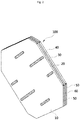
- FIG. 1 is an exploded perspective view illustrating an air guide-integrated evaporation cooler according to an exemplary embodiment of the present invention
- FIG. 2 is a perspective view illustrating a coupled state of the air guide-integrated evaporation cooler shown in FIG. 1 .
- an air guide-integrated evaporation cooler 100 includes first to fourth barrier plates 10, 20, 30, and 40, a pair of first gap units 50 each interposed between the first barrier plate 10 and the second barrier plate 20 and between the third barrier plate 30 and the fourth barrier plate 40 and configured to determine flow directions of fluids in a heat exchanger of a dry channel DC and the dry channel DC, and a second gap unit 60 positioned between the second barrier plate 20 and the third barrier plate 30 and configured to determine flow directions of fluids in a heat exchanger of a wet channel WC and the wet channel WC.
- Each of the first to fourth barrier plates 10, 20, 30, and 40 has a shape of a thin plate and an overall octagonal shape after vertex portions of a rhombus shape have been cut.
- Such first to fourth barrier plates 10, 20, 30, and 40 have small thicknesses, and pluralities of embossings 11, 21, 31, and 41 are respectively formed on the first to fourth barrier plates 10, 20, 30, and 40 in one or both directions to prevent the first to fourth barrier plates 10, 20, 30, and 40 from being deformed due to the small thickness thereof.
- first gap unit 50 and the second gap unit 60 are similar to each other, there is a difference in that the first gap unit 50 and the second gap unit 60 provides paths through which air flows in diagonal directions opposite to each other (that is, counterflow directions) when positioned between the first to fourth barrier plates 10, 20, 30, and 40.
- a flow direction of air which passes through the dry channel DC formed with the first barrier plate 10, the first gap unit 50, and the second barrier plate 20 is a direction from a lower left side toward an upper right side in the drawing
- a flow direction of water and exhausted air which pass through the wet channel WC is a direction from an upper left side toward a lower right side thereof.
- Air exhausted to the outside through the wet channel WC may also be formed as indoor air introduced through a path different from the dry channel DC.
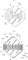
- FIG. 3A is a configuration diagram of a state in which the first barrier plate 10 and the first gap unit 50 shown in FIG. 1 overlap each other
- FIG. 3B is a configuration diagram of a state in which the second barrier plate 20 and the first gap unit 50 shown in FIG. 1 overlap each other.
- the dry channel DC provided at one side of the wet channel WC is formed with the first barrier plate 10, the first gap unit 50, and the second barrier plate 20.
- the first gap unit 50 is formed with a pair of guides 51 (51a and 51b) configured to determine a direction in which air flows, a plurality of bars 52 separated from the guides 51, spaced predetermined distances from each other in a horizontal direction which is a diagonal direction of the first barrier plate 10, and arranged in parallel.
- the pair of guides 51a and 51b of the first gap unit 50 forming a part of the dry channel DC are positioned to be opposite each other at a perimeter of an edge of the first barrier plate 10 in the drawings such that lower left and upper right sides thereof are open.
- the guide 51a positioned at one side in the first gap unit 50 is formed with a guide body 51-1a, a first guide extension 51-2a which extends from an upper end of the guide body 51-1a, and a second guide extension 51-3a which extends from a lower end of the guide body 51-1a.
- the guide body 51-1a is obliquely formed to have a length the same as that of an upper left side of the second barrier plate 20 in an octagonal shape.
- the first guide extension 51-2a is bent and extends from the upper end of the guide body 51-1a in a horizontal direction to have a length the same as that of an upper side of the second barrier plate 20.
- the second guide extension 51-3a is bent and extends downward from the lower end of the guide body 51-1a to have a length the same as that of a left side of the second barrier plate 20, and positioned at a side of the plurality of bars 52.
- the guide 51b positioned at the other side in the first gap unit 50 has a shape the same as that of the guide 51a positioned at the one side in the first gap unit 50, and is formed with a guide body 51-1b positioned to be opposite the guide body 51-1a, a first guide extension 51-2b positioned to be opposite the first guide extension 51-2a, a second guide extension 51-3b positioned to be opposite the second guide extension 51-3a.
- air introduced through an inclined opening DCI positioned at a lower left side moves upward through a dry channel heat exchanger 54 formed with the plurality of bars 52 and spaces 53 therebetween.
- the dry channel heat exchanger 54 is in contact with a heat exchanger 64 of the wet channel WC to exchange heat, and air which passes through the dry channel heat exchanger 54 is cooled by the heat exchange.
- the air cooled by the dry channel heat exchanger 54 is discharged to the interior through an opening DCO positioned at an upper right side of the first and second barrier plates 10 and 20 for cooling the interior.
- Each of the bars 52 may be formed to be hollow in the shape of a pipe with a rectangular cross section. One side surface of the bar 52 is in contact and coupled with the first barrier plate 10 and the other side surface is in contact and coupled with the second barrier plate 20. Air which passes through the dry channel DC flows through the spaces 53 between the adjacent bars 52 and spaces inside the hollow bars 52.
- the bars 52 may facilitate heat exchange by increasing a surface area of the dry channel heat exchanger 54, in place of a conventional fin.
- the embossings 11 and 21 provide rigidity by which the shapes of the first barrier plate 10 and the second barrier plate 20 as described above as well as the air flow paths may be maintained.
- Heights of the embossings 11 and 21 of the first barrier plate 10 and the second barrier plate 20 may be half the protruding heights of the bars 52 and the guides 51, an end of the embossing 11 of the first barrier plate 10 and an end of the embossing 21 of the second barrier plate 20 may be in contact with each other.
- the embossings 11 and 21 are respectively formed on the first barrier plate 10 and the second barrier plate 20 in plurality, and the embossings 11 and 21 are vertically disposed when installed.
- the plurality of the embossings 11 and 21 may protrude in one directions of the first barrier plate 10 and the second barrier plate 20 and may also protrude in both directions thereof.
- all the plurality of embossings 11 formed on the first barrier plate 10 may protrude rightward from a right side surface thereof, and all the plurality of embossings 21 formed on the second barrier plate 20 may protrude leftward from a left side surface thereof.
- the plurality of the embossings 11 and 21 protrude in both directions, some of the plurality of embossings 11 formed on the first barrier plate 10 may protrude rightward, the remaining embossings 11 may protrude leftward, some of the plurality of embossings 21 formed on the second barrier plate 20 may protrude rightward, and the remaining embossings 21 may protrude leftward.
- protruding directions of the pluralities of embossings 11 and 21 may be different from each other, and upper and lower embossings 11 and 21 may also alternately protrude up and down.
- the embossings 11 and 21 may have a long rectangular structure of which both ends are positioned at two sides at which the first and second barrier plates 10 and 20 face each other.
- the embossings 11 and 21 formed on the first barrier plate 10 and the second barrier plate 20 have been described in the above description, the embossings 31 and 41 respectively formed on the third barrier plate 30 and the fourth barrier plate 40 are formed in shapes the same as those of the embossings 11 and 21.
- FIG. 4 is a cross-sectional view taken along line A-A shown in FIG. 3A .
- embossings 11 and 21 protruding from the first barrier plate 10 and the second barrier plate 20 in directions to face each other are in contact with each other, and although not illustrated in the drawing, the other embossings 11 and 21 protruding in directions opposite each other are spaced apart from each other and form spaces.
- the pair of guides 51 are positioned at an edge between the first barrier plate 10 and the second barrier plate 20 to prevent air from leaking, and guide air to flow in a predetermined direction (from the DCI to the DCO).
- the dry channel DC positioned at one side of the air guide-integrated evaporation cooler 100 may be formed by using the first barrier plate 10, the first gap unit 50, and the second barrier plate 20.
- a portion at which the bars 52 are positioned in the first barrier plate 10 and the second barrier plate 20 is the heat exchanger 54, and the remaining portion thereof is air guides 55 and 56 in which a direction of an air flow is determined by the guides 51.
- the heat exchanger 54 and the air guides 55 and 56 respectively provided above and below the heat exchanger 54 may be integrally formed.
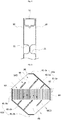
- FIG. 5 is a configuration diagram illustrating the third barrier plate 30 and the second gap unit 60 shown in FIG. 1 .
- the wet channel WC is formed with the second barrier plate 20, the second gap unit 60, and the third barrier plate 30.
- Water and exhausted air are introduced from an upper left side of the wet channel WC, the water evaporates, the second barrier plate 20, the third barrier plate 30, and the second gap unit 60 are cooled, and thus air which passes through the dry channel DC is cooled.
- the second gap unit 60 is formed with a pair of guides 61 (61a and 61b) configured to determine a direction in which air flows and a plurality of bars 62 separated from the guides 61, spaced predetermined distances from each other in a horizontal direction which is a diagonal direction of the second barrier plate 20, and arranged in parallel.
- the guide 61a which is positioned at one side in the second gap unit 60 is formed with a guide body 61-1a, a first guide extension 61-2a which extends from an upper end of the guide body 61-1a, and a second guide extension 61-3a which extends from a lower end of the guide body 61-1a.
- the guide body 61-1a is obliquely formed to have a length the same as that of an upper right side of the third barrier plate 30 formed in an octagonal shape.
- the first guide extension 61-2a is bent and extends from an upper end of the guide body 61-1a in a horizontal direction to have a length the same as that of an upper side of the third barrier plate 30.
- the second guide extension 61-3a is bent and extends downward from a lower end of the guide body 61-1a to have a length the same as that of a right side of the third barrier plate 30, and positioned at a side of the plurality of bars 62.
- the guide 61b positioned at the other side of the second gap unit 60 has a shape the same as that of the guide 61a positioned at the one side of the second gap unit 60, and is formed with a guide body 61-1b positioned to be opposite the guide body 61-1a, a first guide extension 61-2b positioned to be opposite the first guide extension 61-2a, and a second guide extension 61-3b positioned to be opposite the second guide extension 61-3a.
- the bars 62 are spaced predetermined distances from each other in a horizontal direction which is a diagonal direction of the second barrier plate 20 and the same direction of the bars 52 of the first gap unit 50 forming the dry channel DC, and are arranged in parallel.
- Each of the bars 62 may be formed to be hollow in the shape of a pipe with a rectangular cross section. One side surface of the bar 62 is in contact and coupled with the second barrier plate 20 and the other side surface is in contact and coupled with the third barrier plate 30. Water and exhausted air which passes through the wet channel WC flows through spaces 63 between the adjacent bars 62 and spaces inside the hollow bars 62.
- the bars 62 may facilitate heat exchange by increasing a surface area of the wet channel heat exchanger 64, in place of a conventional fin.
- the guides 61 of the second gap unit 60 are provided to be in contact with a perimeter of an edge of the second barrier plate 20 such that an upper left side and a lower right side in the drawing are open.
- embossings 31 formed on the third barrier plate 30 may also protrude rightward and the remaining embossings 31 may also protrude leftward as in the embossings 21 of the second barrier plate 20.
- the embossings 21 of the second barrier plate 20 and the embossings 31 of the third barrier plate 30 protrude in directions to face each other and are in contact with each other, a space may be formed between the second barrier plate 20 and the third barrier plate 30, water may be guided to flow toward upper ends of the bars 62 by the embossings 21 and 31 and is thus evaporated uniformly.
- Directions in which the plurality of embossings 31 protrude may also be different from each other, and the upper and lower embossings 31 may be also formed to alternately protrude up and down.
- the heat exchanger 64 is formed at a position, with which the bars 62 of the second gap unit 60 are in contact, in the second barrier plate 20, the second gap unit 60, the third barrier plate 30 forming the wet channel WC as described above, and air guides 65 and 66 configured to determine flow directions of water and exhausted air are formed at another position, the heat exchanger 64 and the air guides 65 and 66 may be integrally formed, and thus water and air are prevented from leaking therebetween.
- Flow directions of a fluid are 180 degrees opposite each other in the heat exchangers 54 and 64 of the wet channel WC and the dry channel DC, and are perpendicular in the air guides 55, 56, 65, and 66, and thus overall flows of counterflow are generated.
- wet channel WC and the dry channel DC prevent water and air leaks by which fluids are mixed and introduced into the counterflow, heat exchange efficiency may increase. The reason is that high temperature outdoor air which passes through the dry channel DC is prevented from being introduced to the lower temperature wet channel WC.
- the second barrier plate 20, the second gap unit 60, and the third barrier plate 30 form the wet channel WC, and a first gap unit 50 in contact with a surface of the third barrier plate 30 opposite the second gap unit 60 and the fourth barrier plate 40 form another dry channel DC.
- the present invention may have a structure in which the wet channel WC is positioned at a center thereof and dry channels DC are provided at both side surfaces of the wet channel WC, and may be formed with the structure in which a plurality of wet channels WC and dry channels DC are alternately and repeatedly disposed.
- the present invention may have a structure in which the dry channel DC and the wet channel WC are a pair, that is, the dry channel DC is formed at only one side surface of the wet channel WC, and the structure is formed with the first barrier plate 10, the first gap unit 50, the second barrier plate 20, the second gap unit 60, and the third barrier plate 30 in the above drawings.
- positions of the dry channel DC and the wet channel WC may also be changed from the above examples.
- the wet channels WC are positioned at both side surfaces of the dry channel DC.
- All of the first to fourth barrier plates 10, 20, 30, and 40, the first gap unit 50, the second gap unit 60 may be formed of an aluminum material, and particularly, the second barrier plate 20, the third barrier plate 30, and the second gap unit 60 forming the wet channel WC may be surface-treated with a hydrophilic material and used such that water is easily spread on surfaces thereof.
- the first gap unit 50 and the second gap unit 60 may be formed of an aluminum material.
- inner layers of the guides 51 and 61 and the bars 52 and 62 are formed of a 3000 series aluminum and outer layers thereof are formed of a 4000 series aluminum clad having a low melting point, the first gap unit 50 and the second gap unit 60 may be integrally manufactured by single brazing.
- FIG. 6 is a configuration diagram of another embodiment of the present invention, and the air guide-integrated evaporation cooler 100 according to the above-described present invention is manufactured in plurality, and an air guide-integrated evaporation cooler 200 which has a large capacity may be manufactured by coupling the air guide-integrated evaporation coolers 100 to each other.
- brazing in which adhesives are heated at a predetermined temperature for bonding may be used as a method of coupling the air guide-integrated evaporation coolers 100 to each other.
- FIG. 7 is a flowchart of a manufacturing process of the air guide-integrated evaporation cooler according to an exemplary embodiment of the present invention, and a manufacturing method of the air guide-integrated evaporation cooler 100 according to the exemplary embodiment of the present invention will be described with reference to FIG. 7 and the above-described FIGS. 1 to 5 .
- the first to fourth barrier plates 10, 20, 30, and 40 having the same shape are manufactured (operation S10).
- the first to fourth barrier plates (10, 20, 30, and 40) are manufactured to have an octagonal shape after vertex portions of a rhombus shape have been cut (operation S10).
- the first to fourth barrier plates 10, 20, 30, and 40 may be manufactured by using various methods, and the embossings 11, 21, 31, and 41 are also formed in a diagonal direction.
- the guides 51 and 61 respectively form the dry channel DC and the wet channel WC according to applications, shapes thereof are the same.
- operation S20 is separately described from operation S10, operation S20 may be simultaneously performed with the operation S10.
- Operation S30 may also be simultaneously performed with operation S10 and operation S20.
- Operations S40 to S60 are processes of stacking the components provided in operations S10 to S30.
- the pair of guides 51a and 51b and the plurality of bars 52 positioned between the pair of guides 51a and 51b are arranged at the upper portion of the first barrier plate 10, and the dry channel DC is formed by covering the upper portion of the first barrier plate 10 with the second barrier plate 20 (operation S40).
- the pair of guides 61a and 61b and the plurality of bars 62 are arranged at an upper portion of the second barrier plate 20 such that the guides 61a and the 61b are arranged in a mirror direction which is rotated 180 degrees with respect to an arrangement of the guide 51a and 51b, and the wet channel WC is formed by covering the upper portion of the second barrier plate 20 with the third barrier plate 30 (operation S50).
- the pair of guides 51a and 51b and the plurality of bars 52 are arranged at an upper portion of the third barrier plate 30 such that an arrangement thereof is the same as that of the arrangement of the guides 51a and 51b and the plurality of bars 52 arranged at the upper portion of the first barrier plate 10, and the dry channel DC is formed by covering the upper portion of the third barrier plate 30 with the fourth barrier plate 40 (operation S60).
- the first barrier plate 10, the first gap unit 50, the second barrier plate 20, the second gap unit 60, the third barrier plate 30, the first gap unit 50, and the fourth barrier plate 40 are sequentially stacked as described above.
- the first gap unit 50 and the second gap unit 60 includes the bars 52 and 62 forming the heat exchangers 54 and 64 at the same positions, and the guides 51 and 61 disposed such that flow directions of fluids are diagonal directions to each other (opposite directions at portions of the heat exchangers, and perpendicular directions at portions of the air guides).
- the components provided through operation S60 are input to a heating furnace and coupled to each other by brazing (operation S70).
- the barrier plates 10, 20, 30, and 40 and the gap units 50 and 60 are not mechanically coupled, but are integrally bonded by single brazing, and thus a manufacturing process is simple.
Abstract
Description
- The present invention relates to an air guide-integrated evaporation cooler and a method of manufacturing the same, and more particularly, to an air guide-integrated evaporation cooler which is applicable to an evaporating type cooling and dehumidifying apparatus and a method of manufacturing the same.
- Air conditioners, which are generally used as cooling and dehumidifying apparatuses, use refrigerants and are identified as a main cause of ozone depletion and global warming due to refrigerant leakage. In consideration of a problem of using such a refrigerant, energy ventilators which reduce a ventilation load by transmitting sensible heat and latent heat between discharged indoor air and suctioned outdoor air have been developed.
- However, because a latent heat recovery rate is remarkably lower than a sensible heat recovery rate in conventional ventilators, there is a problem in that the conventional ventilators cannot respond to an increase in a cooling load. In consideration of such a conventional energy ventilator, regenerative evaporating type cooling technology has been developed.
- The regenerative evaporating type cooling technology is reduces air temperature using a cooling effect of water evaporation, can solve the problem of the conventional air conditioner because the technology does not use refrigerants except water, and can have an advantageous for sufficiently reducing a cooling load.
- A cooler applied to such a regenerative evaporating type cooler is formed with continuously consecutively repeating wet channels and dry channels. Indoor air and outdoor air are mixed and pass through the dry channel, some air which has passed though the dry channel is exhausted through the wet channel wetted by water, and thus the water is induced to be evaporated. When the water evaporates from a surface of the wet channel, the surface of the wet channel is cooled and absorbs heat of the air which passed through the dry channel, and thus the air which has passed through the dry channel is cooled and supplied to the interior. In order to increase a contact area of a portion of the dry channel and the wet channel at which heat is exchanged, fins bent a plurality of times are used.
- Here, the wet channel to which the exhausted air and water are supplied and the dry channel which supplies cooled air have to be completely separated from each other. To this end, air guides used for the wet channel and the dry channel are installed at a lower portion and an upper portion of structures formed with the alternately repeating wet channels and dry channels.
- As such an example, in Korean Patent Registration No.
10-1055668 - However, in a method in which the dry channel and the wet channel are separately formed and bonded to each other to form the unit module and an air guide is coupled to an upper and a lower portion of the unit module, because each of the components is manufactured individually and a process for assembling the components is required, there may be a problem in that a manufacturing cost increases, and particularly, cooling efficiency decreases because water leaks between the unit module and the air guide or exhausted air in the wet channel and indoor air in the dry channel are mixed.
- Particularly, as the dry channel and the wet channel include fins of which cross section has a wave shape (bent a plurality of times), problems that the fins will be difficult to manufacture and a manufacturing cost thereof will be large may be predicted.
- In addition, in Korean Patent No.
10-1207551 - The present invention is directed to providing an air guide-integrated evaporation cooler in which a plurality of barrier plates, heat exchangers, and air guides for forming a dry channel and a wet channel may be integrally manufactured by a simple process, and a method of manufacturing the same.
- The present invention is also directed to providing an air guide-integrated evaporation cooler in which surface areas of a wet channel and a dry channel of a heat exchanger may increase even without manufacturing a fin bent a plurality of times, and a method of manufacturing the same.
- The present invention is also directed to providing an air guide-integrated evaporation cooler in which a plate which separates a dry channel from a wet channel of a heat exchanger is formed to be thinner than that of a conventional plate and a sufficient rigidity may also be maintained, and a method of manufacturing the same.
- One aspect of the present invention provides an air guide-integrated evaporation cooler which includes a plurality of barrier plates (10, 20, 30, and 40); and gap units (50 and 60) including a plurality of bars (52 and 62) positioned between the plurality of barrier plates (10, 20, 30, and 40), disposed to be spaced apart from each other at a center portion thereof, and configured to form heat exchangers (54 and 64), and guides (51 and 61) disposed at edges of the plurality of barrier plates (10, 20, 30, and 40) and configured to determine a direction of a fluid flow.
- The plurality of barrier plates (10, 20, 30, and 40) may include a first barrier plate, a second barrier plate, and a third barrier plate (10, 20, and 30) which are spaced predetermined distances from each other; a dry channel (DC) through which indoor air and outdoor air flow may be formed between the first barrier plate (10) and the second barrier plate (20); and a wet channel (WC) through which water and exhausted air flow may be formed between the second barrier plate (20) and the third barrier plate (30).
- The gap units (50 and 60) may be formed with a first gap unit (50) provided between the first barrier plate (10) and the second barrier plate (20) and a second gap unit (60) provided between the second barrier plate (20) and the third barrier plate (30); and a fluid flow in the first gap unit (50) may be a counterflow of a fluid flow in the second gap unit (60).
- A plurality of embossings (11, 21, 31, and 41) may respectively protrude from the barrier plates (10, 20, 30, and 40) in a direction of one side thereof, or some of the plurality of embossings (11, 21, 31, and 41) may respectively protrude from the barrier plates (10, 20, 30, and 40) in a direction of one side thereof and the remainder thereof may respectively protrude from the barrier plates (10, 20, 30, and 40) in a direction of the other side thereof.
- Some of the embossings (11, 21, 31, and 41) that protrude toward the dry channel (DC) may have lengths in a direction parallel to a flow direction of the indoor air and the outdoor air.
- The embossings (11, 21, 31, and 41) may be in contact with the embossings on another adjacent barrier plate.
- Pairs of guides (51 and 61) may be provided at edges of one sides and the other sides of the barrier plates (10, 20, 30, and 40) to be opposite each other, and areas thereof in contact with the barrier plates (10, 20, 30, and 40) may be bonded such that the fluid is introduced through one open sides between the pairs of guides (51 and 61), and the fluid is discharged through the other open sides of the pairs of guides (51 and 61).
- The bar (52) may include a plurality of bars spaced predetermined distances in a horizontal direction which is a diagonal direction of the barrier plates (10, 20, 30, and 40), and arranged in parallel.
- The guides (51 and 61) and the bars (52 and 62) may be formed of aluminum clad and the outer layers thereof may be formed of aluminum having a melting point lower than that of the inner layers; and the aluminum clad forming the outer layers may be melted by heat, and the guides (51 and 61) and the bars (52 and 62) may be bonded integrally with the barrier plates (10, 20, 30, and 40).
- The plurality of bars (52 and 62) may be formed to be hollow in a shape of a pipe with a rectangular cross section, each of one side surfaces and the other side surfaces of the bars (52 and 62) may be in contact and coupled with adjacent barrier plates, and the fluid may flow through spaces (53 and 63) between the adjacent bars (52 and 62) and spaces inside the bars (52 and 62).
- Another aspect of the present invention provides a method of manufacturing an air guide-integrated evaporation cooler including a plurality of barrier plates (10, 20, 30, and 40); and gap units (50 and 60) including a plurality of bars (52 and 62) positioned between the plurality of barrier plates (10, 20, 30, and 40), configured to form heat exchangers (54 and 64) by being disposed to be spaced apart from each other at a center portion thereof, and formed with inner layers and outer layers formed of clad, and guides (51 and 61) disposed at edges of the plurality of barrier plates (10, 20, 30, and 40), configured to determine a direction of a fluid flow, and formed inner layers and outer layers formed of clad, the method includes: operation a) providing the plurality of barrier plates (10, 20, 30, and 40), the bars (52 and 62), and the guides (51 and 61); operation b) repeating operations of arranging the bars (52 and 62) and the guides (51 and 61) at an upper portion of one of the plurality of barrier plates (10, 20, 30, and 40), covering the arranged bars (52 and 62) and guides (51 and 61) with the next barrier plates (10, 20, 30, and 40), and arranging the bars (52 and 62) and the guides (51 and 61); and operation c) heating a component provided through the operation b), melting the outer layers having a melting point lower than that of the inner layers of the guides (51 and 61) and the bars (52 and 62), and bonding the barrier plates (10, 20, 30, and 40) to the bars (52 and 62) and the guides (51 and 61) .
- The guides (51 and 61) and bars (52 and 62) may be formed of aluminum clad.
- In the operation b), the guides (51 and 61) and the bars (52 and 62) may be arranged such that flow directions of fluids flowing through the adjacent gap units (50 and 60) with one of the barrier plates (10, 20, 30, and 40) interposed therebetween form counterflow.
- An air guide-integrated evaporation cooler can prevent water and air leaks and improve heat exchange efficiency by integrally coupling a plurality of barrier plates and first and second gap units which are air guides between the barrier plates.
- As thin barrier plates have a sufficient rigidity by forming embossings on the barrier plates, heat exchange efficiency of a heat exchanger can be improved by using the thin barrier plates.
- As surface areas inside a wet channel and a dry channel are increased by using the bars of the first and second gap units, a manufacturing cost can be reduced and productivity can be improved because conventional fins do not need to be manufactured.
- Since the barrier plate, the first gap unit, and the second gap unit are bonded to each other by one brazing process, additional components for mechanical coupling are not necessary, a process time can be reduced, and a cost can be reduced.
-
-
FIG. 1 is an exploded perspective view illustrating an air guide-integrated evaporation cooler according to an exemplary embodiment of the present invention. -
FIG. 2 is a perspective view illustrating a coupled state of the air guide-integrated evaporation cooler shown inFIG. 1 . -
FIG. 3A is a configuration diagram of a state in which a first barrier plate (10) and a first gap unit (50) shown inFIG. 1 overlap each other, andFIG. 3B is a configuration diagram of a state in which a second barrier plate (20) and the first gap unit (50) shown inFIG. 1 overlap each other. -
FIG. 4 is a cross-sectional view taken along line A-A shown inFIG. 3A . -
FIG. 5 is a configuration diagram illustrating a third barrier plate (30) and a second gap unit (60) shown inFIG. 1 . -
FIG. 6 is a configuration diagram of another embodiment of the present invention. -
FIG. 7 is a flowchart of a manufacturing process of the air guide-integrated evaporation cooler according to an exemplary embodiment of the present invention. - Hereinafter, an air guide-integrated evaporation cooler and a method of manufacturing the same according to the present invention will be described in detail with reference to the accompanying drawings.
-
FIG. 1 is an exploded perspective view illustrating an air guide-integrated evaporation cooler according to an exemplary embodiment of the present invention, andFIG. 2 is a perspective view illustrating a coupled state of the air guide-integrated evaporation cooler shown inFIG. 1 . - Referring to
FIGS. 1 and2 , an air guide-integratedevaporation cooler 100 according to the exemplary embodiment of the present invention includes first tofourth barrier plates first gap units 50 each interposed between thefirst barrier plate 10 and thesecond barrier plate 20 and between thethird barrier plate 30 and thefourth barrier plate 40 and configured to determine flow directions of fluids in a heat exchanger of a dry channel DC and the dry channel DC, and asecond gap unit 60 positioned between thesecond barrier plate 20 and thethird barrier plate 30 and configured to determine flow directions of fluids in a heat exchanger of a wet channel WC and the wet channel WC. - Each of the first to
fourth barrier plates fourth barrier plates embossings fourth barrier plates fourth barrier plates - Although shapes of the
first gap unit 50 and thesecond gap unit 60 selectively inserted between the first tofourth barrier plates first gap unit 50 and thesecond gap unit 60 provides paths through which air flows in diagonal directions opposite to each other (that is, counterflow directions) when positioned between the first tofourth barrier plates - That is, there is a difference in the shapes of the
first gap unit 50 and thesecond gap unit 60 such that a flow direction of air which passes through the dry channel DC formed with thefirst barrier plate 10, thefirst gap unit 50, and thesecond barrier plate 20 is a direction from a lower left side toward an upper right side in the drawing, and a flow direction of water and exhausted air which pass through the wet channel WC is a direction from an upper left side toward a lower right side thereof. - Indoor air and outdoor air are mixed and pass through the dry channel DC, some of the air which passed through the dry channel DC is exhausted to the outside through the wet channel WC wetted by water, and thus the water is induced to be evaporated. When the water evaporates from a surface of the wet channel WC, the surface of the wet channel WC is cooled and absorbs heat from air which passes through the dry channel DC, and thus the air which passed through the dry channel DC is cooled and supplied to an interior. Air exhausted to the outside through the wet channel WC may also be formed as indoor air introduced through a path different from the dry channel DC.
-
FIG. 3A is a configuration diagram of a state in which thefirst barrier plate 10 and thefirst gap unit 50 shown inFIG. 1 overlap each other, andFIG. 3B is a configuration diagram of a state in which thesecond barrier plate 20 and thefirst gap unit 50 shown inFIG. 1 overlap each other. - The dry channel DC provided at one side of the wet channel WC is formed with the
first barrier plate 10, thefirst gap unit 50, and thesecond barrier plate 20. - The
first gap unit 50 is formed with a pair of guides 51 (51a and 51b) configured to determine a direction in which air flows, a plurality ofbars 52 separated from theguides 51, spaced predetermined distances from each other in a horizontal direction which is a diagonal direction of thefirst barrier plate 10, and arranged in parallel. - Referring to
FIGS. 3A ,1 , and2 , the pair ofguides first gap unit 50 forming a part of the dry channel DC are positioned to be opposite each other at a perimeter of an edge of thefirst barrier plate 10 in the drawings such that lower left and upper right sides thereof are open. - The
guide 51a positioned at one side in thefirst gap unit 50 is formed with a guide body 51-1a, a first guide extension 51-2a which extends from an upper end of the guide body 51-1a, and a second guide extension 51-3a which extends from a lower end of the guide body 51-1a. - The guide body 51-1a is obliquely formed to have a length the same as that of an upper left side of the
second barrier plate 20 in an octagonal shape. - The first guide extension 51-2a is bent and extends from the upper end of the guide body 51-1a in a horizontal direction to have a length the same as that of an upper side of the
second barrier plate 20. - The second guide extension 51-3a is bent and extends downward from the lower end of the guide body 51-1a to have a length the same as that of a left side of the
second barrier plate 20, and positioned at a side of the plurality ofbars 52. - The
guide 51b positioned at the other side in thefirst gap unit 50 has a shape the same as that of theguide 51a positioned at the one side in thefirst gap unit 50, and is formed with a guide body 51-1b positioned to be opposite the guide body 51-1a, a first guide extension 51-2b positioned to be opposite the first guide extension 51-2a, a second guide extension 51-3b positioned to be opposite the second guide extension 51-3a. - In addition, in such a structure, air introduced through an inclined opening DCI positioned at a lower left side moves upward through a dry
channel heat exchanger 54 formed with the plurality ofbars 52 andspaces 53 therebetween. Here, the drychannel heat exchanger 54 is in contact with aheat exchanger 64 of the wet channel WC to exchange heat, and air which passes through the drychannel heat exchanger 54 is cooled by the heat exchange. The air cooled by the drychannel heat exchanger 54 is discharged to the interior through an opening DCO positioned at an upper right side of the first andsecond barrier plates - Each of the
bars 52 may be formed to be hollow in the shape of a pipe with a rectangular cross section. One side surface of thebar 52 is in contact and coupled with thefirst barrier plate 10 and the other side surface is in contact and coupled with thesecond barrier plate 20. Air which passes through the dry channel DC flows through thespaces 53 between theadjacent bars 52 and spaces inside the hollow bars 52. Thebars 52 may facilitate heat exchange by increasing a surface area of the drychannel heat exchanger 54, in place of a conventional fin. - The
embossings first barrier plate 10 and thesecond barrier plate 20 forming a part of the dry channel DC of such a structure described above. Theembossings first barrier plate 10 and thesecond barrier plate 20 as described above as well as the air flow paths may be maintained. - Heights of the
embossings first barrier plate 10 and thesecond barrier plate 20 may be half the protruding heights of thebars 52 and theguides 51, an end of the embossing 11 of thefirst barrier plate 10 and an end of the embossing 21 of thesecond barrier plate 20 may be in contact with each other. - The
embossings first barrier plate 10 and thesecond barrier plate 20 in plurality, and the embossings 11 and 21 are vertically disposed when installed. - In this case, the plurality of the
embossings first barrier plate 10 and thesecond barrier plate 20 and may also protrude in both directions thereof. - When the plurality of the
embossings embossings 11 formed on thefirst barrier plate 10 may protrude rightward from a right side surface thereof, and all the plurality ofembossings 21 formed on thesecond barrier plate 20 may protrude leftward from a left side surface thereof. - When the plurality of the
embossings embossings 11 formed on thefirst barrier plate 10 may protrude rightward, the remainingembossings 11 may protrude leftward, some of the plurality ofembossings 21 formed on thesecond barrier plate 20 may protrude rightward, and the remainingembossings 21 may protrude leftward. As described above, protruding directions of the pluralities ofembossings - When the plurality of
embossings barrier plates embossings - Although the
embossings embossings second barrier plates - Although the
embossings first barrier plate 10 and thesecond barrier plate 20 have been described in the above description, theembossings third barrier plate 30 and thefourth barrier plate 40 are formed in shapes the same as those of theembossings -
FIG. 4 is a cross-sectional view taken along line A-A shown inFIG. 3A . - Referring to
FIG. 4 , some ofembossings first barrier plate 10 and thesecond barrier plate 20 in directions to face each other are in contact with each other, and although not illustrated in the drawing, the other embossings 11 and 21 protruding in directions opposite each other are spaced apart from each other and form spaces. - The pair of guides 51 (51a and 51b) are positioned at an edge between the
first barrier plate 10 and thesecond barrier plate 20 to prevent air from leaking, and guide air to flow in a predetermined direction (from the DCI to the DCO). - As described above, in the present invention, the dry channel DC positioned at one side of the air guide-integrated
evaporation cooler 100 may be formed by using thefirst barrier plate 10, thefirst gap unit 50, and thesecond barrier plate 20. A portion at which thebars 52 are positioned in thefirst barrier plate 10 and thesecond barrier plate 20 is theheat exchanger 54, and the remaining portion thereof is air guides 55 and 56 in which a direction of an air flow is determined by theguides 51. - That is, in the present invention, the
heat exchanger 54 and the air guides 55 and 56 respectively provided above and below theheat exchanger 54 may be integrally formed. -
FIG. 5 is a configuration diagram illustrating thethird barrier plate 30 and thesecond gap unit 60 shown inFIG. 1 . - Referring to
FIG. 5 , the wet channel WC is formed with thesecond barrier plate 20, thesecond gap unit 60, and thethird barrier plate 30. Water and exhausted air are introduced from an upper left side of the wet channel WC, the water evaporates, thesecond barrier plate 20, thethird barrier plate 30, and thesecond gap unit 60 are cooled, and thus air which passes through the dry channel DC is cooled. - The
second gap unit 60 is formed with a pair of guides 61 (61a and 61b) configured to determine a direction in which air flows and a plurality ofbars 62 separated from the guides 61, spaced predetermined distances from each other in a horizontal direction which is a diagonal direction of thesecond barrier plate 20, and arranged in parallel. - The
guide 61a which is positioned at one side in thesecond gap unit 60 is formed with a guide body 61-1a, a first guide extension 61-2a which extends from an upper end of the guide body 61-1a, and a second guide extension 61-3a which extends from a lower end of the guide body 61-1a. - The guide body 61-1a is obliquely formed to have a length the same as that of an upper right side of the
third barrier plate 30 formed in an octagonal shape. - The first guide extension 61-2a is bent and extends from an upper end of the guide body 61-1a in a horizontal direction to have a length the same as that of an upper side of the
third barrier plate 30. - The second guide extension 61-3a is bent and extends downward from a lower end of the guide body 61-1a to have a length the same as that of a right side of the
third barrier plate 30, and positioned at a side of the plurality ofbars 62. - The
guide 61b positioned at the other side of thesecond gap unit 60 has a shape the same as that of theguide 61a positioned at the one side of thesecond gap unit 60, and is formed with a guide body 61-1b positioned to be opposite the guide body 61-1a, a first guide extension 61-2b positioned to be opposite the first guide extension 61-2a, and a second guide extension 61-3b positioned to be opposite the second guide extension 61-3a. - The
bars 62 are spaced predetermined distances from each other in a horizontal direction which is a diagonal direction of thesecond barrier plate 20 and the same direction of thebars 52 of thefirst gap unit 50 forming the dry channel DC, and are arranged in parallel. - Each of the
bars 62 may be formed to be hollow in the shape of a pipe with a rectangular cross section. One side surface of thebar 62 is in contact and coupled with thesecond barrier plate 20 and the other side surface is in contact and coupled with thethird barrier plate 30. Water and exhausted air which passes through the wet channel WC flows throughspaces 63 between theadjacent bars 62 and spaces inside the hollow bars 62. Thebars 62 may facilitate heat exchange by increasing a surface area of the wetchannel heat exchanger 64, in place of a conventional fin. - Because water and exhausted air supplied to the wet channel WC have to be completely separated from the dry channel DC, the guides 61 of the
second gap unit 60 are provided to be in contact with a perimeter of an edge of thesecond barrier plate 20 such that an upper left side and a lower right side in the drawing are open. - In such a structure, water and exhausted air are supplied through an upper left opening WCI, move downward through the
heat exchanger 64 which is thespaces 63 between thebars 62, and are discharged to the outside through a lower right opening WCO. - Some of the
embossings 31 formed on thethird barrier plate 30 may also protrude rightward and the remainingembossings 31 may also protrude leftward as in theembossings 21 of thesecond barrier plate 20. - When the
embossings 21 of thesecond barrier plate 20 and theembossings 31 of thethird barrier plate 30 protrude in directions to face each other and are in contact with each other, a space may be formed between thesecond barrier plate 20 and thethird barrier plate 30, water may be guided to flow toward upper ends of thebars 62 by the embossings 21 and 31 and is thus evaporated uniformly. - Directions in which the plurality of
embossings 31 protrude may also be different from each other, and the upper andlower embossings 31 may be also formed to alternately protrude up and down. - The
heat exchanger 64 is formed at a position, with which thebars 62 of thesecond gap unit 60 are in contact, in thesecond barrier plate 20, thesecond gap unit 60, thethird barrier plate 30 forming the wet channel WC as described above, and air guides 65 and 66 configured to determine flow directions of water and exhausted air are formed at another position, theheat exchanger 64 and the air guides 65 and 66 may be integrally formed, and thus water and air are prevented from leaking therebetween. Flow directions of a fluid are 180 degrees opposite each other in theheat exchangers - The
second barrier plate 20, thesecond gap unit 60, and thethird barrier plate 30 form the wet channel WC, and afirst gap unit 50 in contact with a surface of thethird barrier plate 30 opposite thesecond gap unit 60 and thefourth barrier plate 40 form another dry channel DC. - That is, the present invention may have a structure in which the wet channel WC is positioned at a center thereof and dry channels DC are provided at both side surfaces of the wet channel WC, and may be formed with the structure in which a plurality of wet channels WC and dry channels DC are alternately and repeatedly disposed.
- In addition, the present invention may have a structure in which the dry channel DC and the wet channel WC are a pair, that is, the dry channel DC is formed at only one side surface of the wet channel WC, and the structure is formed with the
first barrier plate 10, thefirst gap unit 50, thesecond barrier plate 20, thesecond gap unit 60, and thethird barrier plate 30 in the above drawings. - In addition, positions of the dry channel DC and the wet channel WC may also be changed from the above examples. In this case, the wet channels WC are positioned at both side surfaces of the dry channel DC.
- All of the first to
fourth barrier plates first gap unit 50, thesecond gap unit 60 may be formed of an aluminum material, and particularly, thesecond barrier plate 20, thethird barrier plate 30, and thesecond gap unit 60 forming the wet channel WC may be surface-treated with a hydrophilic material and used such that water is easily spread on surfaces thereof. - The
first gap unit 50 and thesecond gap unit 60 may be formed of an aluminum material. In this case, since inner layers of theguides 51 and 61 and thebars first gap unit 50 and thesecond gap unit 60 may be integrally manufactured by single brazing. -
FIG. 6 is a configuration diagram of another embodiment of the present invention, and the air guide-integratedevaporation cooler 100 according to the above-described present invention is manufactured in plurality, and an air guide-integratedevaporation cooler 200 which has a large capacity may be manufactured by coupling the air guide-integratedevaporation coolers 100 to each other. - In this case, brazing in which adhesives are heated at a predetermined temperature for bonding may be used as a method of coupling the air guide-integrated
evaporation coolers 100 to each other. -
FIG. 7 is a flowchart of a manufacturing process of the air guide-integrated evaporation cooler according to an exemplary embodiment of the present invention, and a manufacturing method of the air guide-integratedevaporation cooler 100 according to the exemplary embodiment of the present invention will be described with reference toFIG. 7 and the above-describedFIGS. 1 to 5 . - First, the first to
fourth barrier plates - As illustrated in
FIGS. 1 to 5 , the first to fourth barrier plates (10, 20, 30, and 40) are manufactured to have an octagonal shape after vertex portions of a rhombus shape have been cut (operation S10). Here, the first tofourth barrier plates embossings - Next, the
guides 51 and 61 which are in contact with a part of each edge of the first tofourth barrier plates - Although it has been described that the
guides 51 and 61 respectively form the dry channel DC and the wet channel WC according to applications, shapes thereof are the same. - For the sake of convenience in the description, although operation S20 is separately described from operation S10, operation S20 may be simultaneously performed with the operation S10.
- Next, the
bars heat exchangers - Operations S40 to S60 are processes of stacking the components provided in operations S10 to S30.
- First, the pair of
guides bars 52 positioned between the pair ofguides first barrier plate 10, and the dry channel DC is formed by covering the upper portion of thefirst barrier plate 10 with the second barrier plate 20 (operation S40). - Next, the pair of
guides bars 62 are arranged at an upper portion of thesecond barrier plate 20 such that theguides 61a and the 61b are arranged in a mirror direction which is rotated 180 degrees with respect to an arrangement of theguide second barrier plate 20 with the third barrier plate 30 (operation S50). - Next, the pair of
guides bars 52 are arranged at an upper portion of thethird barrier plate 30 such that an arrangement thereof is the same as that of the arrangement of theguides bars 52 arranged at the upper portion of thefirst barrier plate 10, and the dry channel DC is formed by covering the upper portion of thethird barrier plate 30 with the fourth barrier plate 40 (operation S60). - The
first barrier plate 10, thefirst gap unit 50, thesecond barrier plate 20, thesecond gap unit 60, thethird barrier plate 30, thefirst gap unit 50, and thefourth barrier plate 40 are sequentially stacked as described above. In this case, thefirst gap unit 50 and thesecond gap unit 60 includes thebars heat exchangers guides 51 and 61 disposed such that flow directions of fluids are diagonal directions to each other (opposite directions at portions of the heat exchangers, and perpendicular directions at portions of the air guides). - The components provided through operation S60 are input to a heating furnace and coupled to each other by brazing (operation S70).
- That is, when the components provided through operation S60 are heated at a predetermined temperature, the outer layers of the
guides 51 and 61 and thebars fourth barrier plates - Accordingly, in the present invention, the
barrier plates gap units - In addition, because a fluid is not leaked between the
barrier plates gap units - The present invention is not limited to the above-described embodiments, and it is clear to those skilled in the art that the present invention can be variously modified, changed, and performed without departing from the technological scope of the present invention.
| 10: | FIRST BARRIER PLATE | 20: | SECOND BARRIER PLATE |
| 30: | THIRD BARRIER PLATE | 40: | FOURTH BARRIER PLATE |
| 50: | FIRST GAP UNIT | 60: | SECOND GAP UNIT |
| 11, 21, 31, 41: | EMBOSSING | 51, 61: | |
| 52, 62: | BAR |
Claims (13)
- An air guide-integrated evaporation cooler comprising:a plurality of barrier plates (10, 20, 30, 40); andgap units (50, 60) including a plurality of bars (52, 62) positioned between the plurality of barrier plates (10, 20, 30, 40), disposed to be spaced apart from each other at a center portion thereof, and configured to form heat exchangers (54, 64), and guides (51, 61) disposed at edges of the plurality of barrier plates (10, 20, 30, 40) and configured to determine a direction of a fluid flow.
- The air guide-integrated evaporation cooler of claim 1, wherein:the plurality of barrier plates (10, 20, 30, 40) include a first barrier plate, a second barrier plate, and a third barrier plate (10, 20, 30) which are spaced predetermined distances from each other;a dry channel (DC) through which indoor air and outdoor air flow is formed between the first barrier plate (10) and the second barrier plate (20); anda wet channel (WC) through which water and exhausted air flow is formed between the second barrier plate (20) and the third barrier plate (30).
- The air guide-integrated evaporation cooler of claim 2, wherein:the gap units (50, 60) are formed with a first gap unit (50) provided between the first barrier plate (10) and the second barrier plate (20) and a second gap unit (60) provided between the second barrier plate (20) and the third barrier plate (30); anda fluid flow in the first gap unit (50) is a counterflow of a fluid flow in the second gap unit (60).
- The air guide-integrated evaporation cooler of claim 2, wherein:a plurality of embossings (11, 21, 31, 41) respectively protrude from the barrier plates (10, 20, 30, 40) in a direction of one side thereof; orsome of the plurality of embossings (11, 21, 31, 41) respectively protrude from the barrier plates (10, 20, 30, and 40) in a direction of one side thereof and the remainder thereof respectively protrude from the barrier plates (10, 20, 30, 40) in a direction of the other side thereof.
- The air guide-integrated evaporation cooler of claim 4, wherein some of the embossings (11, 21, 31, 41) that protrude toward the dry channel (DC) have lengths in a direction parallel to a flow direction of the indoor air and the outdoor air.
- The air guide-integrated evaporation cooler of claim 4, wherein the embossings (11, 21, 31, 41) are in contact with the embossings on another adjacent barrier plate.
- The air guide-integrated evaporation cooler of claim 1, wherein pairs of guides (51, 61) are provided at edges of one sides and the other sides of the barrier plates (10, 20, 30, 40) to be opposite each other, and areas thereof in contact with the barrier plates (10, 20, 30, 40) are bonded such that the fluid is introduced through one open sides between the pairs of guides (51, 61), and the fluid is discharged through the other open sides of the pairs of guides (51, 61).
- The air guide-integrated evaporation cooler of claim 7, wherein the bar (52, 62) includes a plurality of bars spaced predetermined distances in a horizontal direction, which is a diagonal direction of the barrier plates (10, 20, 30, 40), and arranged in parallel.
- The air guide-integrated evaporation cooler of claim 1, wherein:the guides (51, 61) and the bars (52, 62) are formed of aluminum clad and the outer layers thereof are formed of aluminum having a melting point lower than that of the inner layers; andthe aluminum clad forming the outer layers is melted by heat, and the guides (51, 61) and the bars (52, 62) are integrally bonded to the barrier plates (10, 20, 30, 40).
- The air guide-integrated evaporation cooler of claim 1, wherein:the plurality of bars (52, 62) are formed to be hollow in a shape of a pipe with a rectangular cross section;each of one side surfaces and the other side surfaces of the bars (52, 62) is in contact and coupled with adjacent barrier plates; andthe fluid flows through spaces (53, 63) between the adjacent bars (52, 62) and spaces inside the bars (52, 62).
- A method of manufacturing an air guide-integrated evaporation cooler comprising:a plurality of barrier plates (10, 20, 30, 40); andgap units (50, 60) including a plurality of bars (52, 62) positioned between the plurality of barrier plates (10, 20, 30, 40), configured to form heat exchangers (54, 64) by being disposed to be spaced apart from each other at a center portion thereof, and formed with inner layers and outer layers formed of clad, and guides (51, 61) disposed at edges of the plurality of barrier plates (10, 20, 30, 40), configured to determine a direction of a fluid flow, and formed inner layers and outer layers formed of clad, the method comprising:operation a) providing the plurality of barrier plates (10, 20, 30, 40), the bars (52, 62), and the guides (51, 61);operation b) repeating operations of arranging the bars (52, 62) and the guides (51, 61) at an upper portion of one of the plurality of barrier plates (10, 20, 30, 40), covering the arranged bars (52, 62) and guides (51, 61) with the next barrier plates (10, 20, 30, 40), and arranging the bars (52, 62) and the guides (51, 61); andoperation c) heating a component provided through the operation b), melting the outer layers having a melting point lower than that of the inner layers of the guides (51, 61) and the bars (52, 62), and bonding the barrier plates (10, 20, 30, 40) to the bars (52, 62) and the guides (51, 61).
- The method of claim 11, wherein the guides (51, 61) and bars (52, 62) are formed of aluminum clad.
- The method of claim 11, wherein, in the operation b), the guides (51, 61) and the bars (52, 62) are arranged such that flow directions of fluids flowing through the adjacent gap units (50, 60) with one of the barrier plates (10, 20, 30, 40) interposed therebetween form counterflow.
Applications Claiming Priority (2)
| Application Number | Priority Date | Filing Date | Title |
|---|---|---|---|
| KR20140114178 | 2014-08-29 | ||
| PCT/KR2015/009071 WO2016032283A1 (en) | 2014-08-29 | 2015-08-28 | Air guide-integrated evaporation cooler and method for manufacturing same |
Publications (2)
| Publication Number | Publication Date |
|---|---|
| EP3187809A1 true EP3187809A1 (en) | 2017-07-05 |
| EP3187809A4 EP3187809A4 (en) | 2018-05-23 |
Family
ID=55537002
Family Applications (1)
| Application Number | Title | Priority Date | Filing Date |
|---|---|---|---|
| EP15835727.7A Withdrawn EP3187809A4 (en) | 2014-08-29 | 2015-08-28 | Air guide-integrated evaporation cooler and method for manufacturing same |
Country Status (5)
| Country | Link |
|---|---|
| US (1) | US10215498B2 (en) |
| EP (1) | EP3187809A4 (en) |
| JP (1) | JP2017521629A (en) |
| KR (1) | KR20160026786A (en) |
| CN (1) | CN107003075A (en) |
Cited By (2)
| Publication number | Priority date | Publication date | Assignee | Title |
|---|---|---|---|---|
| CN110004681A (en) * | 2019-04-16 | 2019-07-12 | 广东技术师范大学 | A kind of interior circulation clothes-drying machine and drying system |
| EP3789717A1 (en) * | 2019-09-06 | 2021-03-10 | Hamilton Sundstrand Corporation | Heat exchanger vane with partial height airflow modifier |
Families Citing this family (3)
| Publication number | Priority date | Publication date | Assignee | Title |
|---|---|---|---|---|
| FR3050519B1 (en) * | 2016-04-25 | 2019-09-06 | Novares France | HEAT EXCHANGER OF PLASTIC MATERIAL AND VEHICLE COMPRISING THIS HEAT EXCHANGER |
| CN109442806B (en) * | 2018-09-03 | 2020-11-10 | 广东工业大学 | Liquid-separation phase-change plate heat exchanger and application thereof |
| CN111615291B (en) * | 2019-02-25 | 2023-04-11 | 富联精密电子(天津)有限公司 | Immersion cooling device |
Family Cites Families (29)
| Publication number | Priority date | Publication date | Assignee | Title |
|---|---|---|---|---|
| US3587730A (en) * | 1956-08-30 | 1971-06-28 | Union Carbide Corp | Heat exchange system with porous boiling layer |
| US3995689A (en) * | 1975-01-27 | 1976-12-07 | The Marley Cooling Tower Company | Air cooled atmospheric heat exchanger |
| US4966230A (en) * | 1989-01-13 | 1990-10-30 | Modine Manufacturing Co. | Serpentine fin, round tube heat exchanger |
| JP2677485B2 (en) * | 1992-04-03 | 1997-11-17 | 昭和アルミニウム株式会社 | Multilayer evaporator |
| US5514248A (en) * | 1990-08-20 | 1996-05-07 | Showa Aluminum Corporation | Stack type evaporator |
| JPH05196386A (en) * | 1991-11-22 | 1993-08-06 | Nippondenso Co Ltd | Laminated plate type heat exchanger |
| FR2689219A1 (en) * | 1992-03-30 | 1993-10-01 | Carrier Sa | Fluid refrigeration device; its application to air treatment; ice production and storage tank and tubular heat exchange bundle clean to be part of such a device. |
| AU663964B2 (en) * | 1992-08-31 | 1995-10-26 | Mitsubishi Jukogyo Kabushiki Kaisha | Stacked heat exchanger |
| JP3045643B2 (en) * | 1994-10-05 | 2000-05-29 | 鹿島建設株式会社 | Heat exchanger |
| JP3651938B2 (en) | 1994-10-24 | 2005-05-25 | 松下エコシステムズ株式会社 | Heat exchange element |
| JP2000304475A (en) | 1999-04-21 | 2000-11-02 | Matsushita Electric Ind Co Ltd | Laminated heat exchanger |
| JP4605925B2 (en) * | 2001-03-08 | 2011-01-05 | サンデン株式会社 | Laminate heat exchanger |
| CN1575404A (en) * | 2001-10-25 | 2005-02-02 | 昭和电工株式会社 | Heat exchanger, fluorination method of heat exchanger or its components and manufacturing method of heat exchanger |
| AU2002346722B2 (en) * | 2001-12-12 | 2007-12-06 | F.F. Seeley Nominees Pty. Ltd. | Method and plate apparatus for dew point evaporative cooler |
| JP2006071150A (en) | 2004-08-31 | 2006-03-16 | Nitta Ind Corp | Heat exchanging element |
| JP3115169U (en) * | 2005-07-28 | 2005-11-04 | 有限会社倭工房 | Total heat exchanger |
| JP2007078258A (en) * | 2005-09-14 | 2007-03-29 | Tokyo Roki Co Ltd | Stacked heat exchanger |
| JP2007139333A (en) * | 2005-11-18 | 2007-06-07 | Max Co Ltd | Ventilating device and building |
| JP2007147117A (en) * | 2005-11-24 | 2007-06-14 | Max Co Ltd | Indirect evaporative cooling element, air conditioner, and building |
| US20110120693A1 (en) * | 2006-07-14 | 2011-05-26 | Az Evap, Llc | Integrated evaporative cooler and flat plate air to air heat exchanger |
| JP2009154862A (en) * | 2007-12-06 | 2009-07-16 | Earth Clean Tohoku:Kk | Air conditioning system of electric vehicle |
| JP4565417B2 (en) * | 2007-12-18 | 2010-10-20 | 株式会社アースクリーン東北 | Indirect vaporization cooling system |
| US20090178426A1 (en) * | 2008-01-16 | 2009-07-16 | Mohinder Singh Bhatti | Evaporative heat exchanger for cooling a refrigerant |
| KR101055668B1 (en) | 2008-11-20 | 2011-08-10 | 한국과학기술연구원 | Core module of regenerative evaporative air conditioner and its manufacturing method |
| JP3159566U (en) * | 2010-02-26 | 2010-05-27 | 株式会社アースクリーン東北 | Indirect vaporization cooling system |
| JP5619538B2 (en) * | 2010-09-06 | 2014-11-05 | 株式会社ティラド | Fluxless brazing method of heat exchanger having narrow channel inner fin and aluminum clad material used therefor |
| KR101207551B1 (en) | 2011-02-10 | 2012-12-03 | 주식회사 원진 | Recyling Evaporation Cooler |
| JP5747879B2 (en) | 2012-08-01 | 2015-07-15 | カルソニックカンセイ株式会社 | Heat exchanger |
| KR101368309B1 (en) | 2013-08-12 | 2014-02-27 | (주)월드이엔씨 | Heat exchanger for exhaust heat recovery |
-
2015
- 2015-08-28 US US15/506,843 patent/US10215498B2/en active Active
- 2015-08-28 EP EP15835727.7A patent/EP3187809A4/en not_active Withdrawn
- 2015-08-28 JP JP2016571731A patent/JP2017521629A/en active Pending
- 2015-08-28 CN CN201580037943.4A patent/CN107003075A/en not_active Withdrawn
- 2015-08-28 KR KR1020150121756A patent/KR20160026786A/en active Search and Examination
Cited By (3)
| Publication number | Priority date | Publication date | Assignee | Title |
|---|---|---|---|---|
| CN110004681A (en) * | 2019-04-16 | 2019-07-12 | 广东技术师范大学 | A kind of interior circulation clothes-drying machine and drying system |
| EP3789717A1 (en) * | 2019-09-06 | 2021-03-10 | Hamilton Sundstrand Corporation | Heat exchanger vane with partial height airflow modifier |
| US11209223B2 (en) | 2019-09-06 | 2021-12-28 | Hamilton Sundstrand Corporation | Heat exchanger vane with partial height airflow modifier |
Also Published As
| Publication number | Publication date |
|---|---|
| KR20160026786A (en) | 2016-03-09 |
| US20170276434A1 (en) | 2017-09-28 |
| CN107003075A (en) | 2017-08-01 |
| US10215498B2 (en) | 2019-02-26 |
| EP3187809A4 (en) | 2018-05-23 |
| JP2017521629A (en) | 2017-08-03 |
Similar Documents
| Publication | Publication Date | Title |
|---|---|---|
| US10215498B2 (en) | Air guide-integrated evaporation cooler and method for manufacturing same | |
| US9459053B2 (en) | Heat exchanger and air-conditioning apparatus | |
| JP6038302B2 (en) | Laminated header, heat exchanger, and air conditioner | |
| JP6012857B2 (en) | Laminated header, heat exchanger, and air conditioner | |
| JP6005267B2 (en) | Laminated header, heat exchanger, and air conditioner | |
| JP6116683B2 (en) | Laminated header, heat exchanger, and air conditioner | |
| JP6005266B2 (en) | Laminated header, heat exchanger, and air conditioner | |
| US10224263B2 (en) | Heat exchanger | |
| JP6005268B2 (en) | Laminated header, heat exchanger, and air conditioner | |
| EP3088831B1 (en) | Heat exchanger and air conditioning apparatus | |
| US20200072478A1 (en) | Air-conditioner outdoor heat exchanger and air-conditioner including the same | |
| KR20140106493A (en) | Air conditioner | |
| WO2020262666A1 (en) | Heat exchanger and heat pump apparatus | |
| JP2001041678A (en) | Heat exchanger | |
| WO2017195588A1 (en) | Stack type heat exchanger | |
| JP6537760B1 (en) | Heat exchange element and heat exchange ventilator | |
| KR20160115892A (en) | Heat transfer device and method for manufacturing thereof | |
| US11815316B2 (en) | Heat exchanger and heat pump system having same | |
| US11619427B2 (en) | Heat exchanger and heat pump system having same | |
| JP6601380B2 (en) | Heat exchanger and air conditioner | |
| KR102076679B1 (en) | A heat exchanger and a natural coolant circulation air conditioner | |
| JP2011242089A (en) | Laminated heat exchanger | |
| JP2020079651A (en) | Air conditioner | |
| EP2957853A1 (en) | Heat exchanger for air conditioning system | |
| JP2019066132A (en) | Multi-path type heat exchanger and refrigeration system using the same |
Legal Events
| Date | Code | Title | Description |
|---|---|---|---|
| PUAI | Public reference made under article 153(3) epc to a published international application that has entered the european phase |
Free format text: ORIGINAL CODE: 0009012 |
|
| 17P | Request for examination filed |
Effective date: 20170328 |
|
| AK | Designated contracting states |
Kind code of ref document: A1 Designated state(s): AL AT BE BG CH CY CZ DE DK EE ES FI FR GB GR HR HU IE IS IT LI LT LU LV MC MK MT NL NO PL PT RO RS SE SI SK SM TR |
|
| AX | Request for extension of the european patent |
Extension state: BA ME |
|
| DAV | Request for validation of the european patent (deleted) | ||
| DAX | Request for extension of the european patent (deleted) | ||
| A4 | Supplementary search report drawn up and despatched |
Effective date: 20180419 |
|
| RIC1 | Information provided on ipc code assigned before grant |
Ipc: F28F 13/00 20060101ALI20180413BHEP Ipc: F28F 3/04 20060101ALI20180413BHEP Ipc: F28D 21/00 20060101ALI20180413BHEP Ipc: F28D 9/00 20060101AFI20180413BHEP Ipc: F28F 3/02 20060101ALI20180413BHEP |
|
| STAA | Information on the status of an ep patent application or granted ep patent |
Free format text: STATUS: THE APPLICATION HAS BEEN WITHDRAWN |
|
| 18W | Application withdrawn |
Effective date: 20181025 |