EP3187374A1 - Dispositif porte-objet convertible - Google Patents
Dispositif porte-objet convertible Download PDFInfo
- Publication number
- EP3187374A1 EP3187374A1 EP16207429.8A EP16207429A EP3187374A1 EP 3187374 A1 EP3187374 A1 EP 3187374A1 EP 16207429 A EP16207429 A EP 16207429A EP 3187374 A1 EP3187374 A1 EP 3187374A1
- Authority
- EP
- European Patent Office
- Prior art keywords
- cover portion
- lining
- opening
- front surface
- elastically deformable
- Prior art date
- Legal status (The legal status is an assumption and is not a legal conclusion. Google has not performed a legal analysis and makes no representation as to the accuracy of the status listed.)
- Granted
Links
- 230000008878 coupling Effects 0.000 claims abstract description 6
- 238000010168 coupling process Methods 0.000 claims abstract description 6
- 238000005859 coupling reaction Methods 0.000 claims abstract description 6
- 239000000463 material Substances 0.000 claims description 7
- 241000761557 Lamina Species 0.000 claims description 3
- 238000005273 aeration Methods 0.000 claims description 2
- 238000005452 bending Methods 0.000 claims description 2
- 238000004891 communication Methods 0.000 claims description 2
- 239000004744 fabric Substances 0.000 description 3
- 230000010354 integration Effects 0.000 description 3
- 239000010410 layer Substances 0.000 description 2
- 229910052751 metal Inorganic materials 0.000 description 2
- 241001465754 Metazoa Species 0.000 description 1
- 230000015572 biosynthetic process Effects 0.000 description 1
- 230000008859 change Effects 0.000 description 1
- 239000013013 elastic material Substances 0.000 description 1
- 239000010985 leather Substances 0.000 description 1
- 239000002649 leather substitute Substances 0.000 description 1
- 239000007769 metal material Substances 0.000 description 1
- 230000004048 modification Effects 0.000 description 1
- 238000012986 modification Methods 0.000 description 1
- 238000007665 sagging Methods 0.000 description 1
- 239000002356 single layer Substances 0.000 description 1
- 230000007704 transition Effects 0.000 description 1
Images


Classifications
-
- B—PERFORMING OPERATIONS; TRANSPORTING
- B60—VEHICLES IN GENERAL
- B60R—VEHICLES, VEHICLE FITTINGS, OR VEHICLE PARTS, NOT OTHERWISE PROVIDED FOR
- B60R7/00—Stowing or holding appliances inside vehicle primarily intended for personal property smaller than suit-cases, e.g. travelling articles, or maps
- B60R7/04—Stowing or holding appliances inside vehicle primarily intended for personal property smaller than suit-cases, e.g. travelling articles, or maps in driver or passenger space, e.g. using racks
Definitions
- the present invention relates to a convertible object-holder device.
- the present invention relates to an object-holder device provided on the dashboard of a motor vehicle.
- object-holder devices such as pockets, drawers, shelves and doors, in which relatively small objects (bottles, sheets, pens, mobile phone, etc.) can be stowed.
- object-holder devices such as pockets, drawers, shelves and doors, in which relatively small objects (bottles, sheets, pens, mobile phone, etc.) can be stowed.
- these devices can be provided on the dashboard, in the door panels, in the tunnel console, behind the seats, on the sides of the boot, etc.
- a solution of this type is known for example from EP1861289 , in which a fabric has an elastic band embedded therein, the band defining two stable configurations, with opposite curvatures, corresponding to the two operating conditions indicated above.
- the elastic band is curved so as to stretch the fabric and form a pocket, the latter has a top access opening that is permanently open, so that the objects stowed in this pocket are visible from the outside of the motor vehicle. Instead, it is preferable to hide the objects in an object-holder drawer which can be completely closed, especially if such drawer is to be provided on the dashboard of the motor vehicle.
- the object of the present invention is to provide a convertible object-holder device, which allows the requirements outlined above to be met in a simple and inexpensive way, and which, preferably, can be removed from a motor vehicle so as to be used as a bag and/or be positioned interchangeably in different areas of the motor vehicle.
- a convertible object-holder device is provided as defined in claim 1.
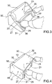
- the reference number 1 indicates an object-holder device, which is convertible between a first operating condition ( Fig. 5 ), in which it defines a glove box compartment, preferably of a parallelepiped shape, and a second operating condition ( Fig. 1 ), in which it is folded so as to eliminate the glove box compartment, which, therefore, is of the concealed type.
- the device 1 defines a covering of a bracket for supporting objects, or a covering of a recess suitable for housing these objects.
- the device 1 comprises a support structure 3 having a front surface 4 shaped so as to define a cavity or recess 5 elongated along a direction 6 which is substantially horizontal.
- the front surface 4 of the structure 3 has an L-shaped side profile, when sectioned with section planes orthogonal to direction 6, therefore, the cavity 5 has a base surface 7, defining a substantially horizontal shelf or bracket, and an abutment surface 8 transverse to the base surface and defining a substantially vertical shoulder.
- the structure 3 consists of two walls 9 and 10 orthogonal and fixed to each other, and defining, respectively, the base surface 7 and the abutment surface 8.
- the walls 9 and 10 are hinged to one another about an axis parallel to direction 6 in order to be able to close and compact the device 1 when the latter is configured in the second operative condition.
- the walls 9 and 10 are locked in positions orthogonal to one another by a retaining system of the releasable type in order to maintain the first operating condition during use.
- the cross section of the front surface 4 has a concave shape different from the L shape (for example, a shape such as that shown in Figure 11 ).
- the device 1 also comprises a lining 11, which is made of a flexible or foldable sheet material, for example fabric, leather, artificial leather, etc.
- the material of the lining 11 can be of the monolayer or multilayer type.
- the flexible material of the lining 11 may define a network.
- the lining 11 is fixed to the structure 3 in a known manner, which is not described in detail, and comprises two end flaps 12 and 13 arranged on the structure 3 in fixed positions next to respective regions 14 and 15. The latter are spaced apart along a direction 16 orthogonal to direction 6 and thus are arranged on opposite sides of the cavity 5.
- the areas 14 and 15 are defined, respectively, by the ends of the walls 9 and 10.
- the lining 11 comprises a cover portion 20 having an outer surface 21 and an inner surface 22 opposite to each other.
- the surface 22 faces the front surface 4.
- the cover portion 20 consists of an intermediate area 23 and two areas 24 and 25, which are substantially flat when the device 1 is in the above-mentioned first or second operating condition.
- the area 23 joins together the areas 24 and 25 and defines a virtual hinge so as to be able to fold the areas 24 and 25 relative to each other around a rectilinear axis 27, which is preferably parallel to direction 6.
- the lining 11 further comprises two folding portions 29 and 30, which are arranged on opposite sides of the cover portion 20 and in positions adjacent to the flaps 12 and 13, respectively.
- the portions 29 and 30 join the area 24 to the flap 12 and the area 25 to the flap 13.
- the portions 29 and 30 define virtual hinges to allow the cover portion 20 to be folded with respect to the flaps 12, 13 and to the structure 3 about respective folding axes 31 and 32, which are preferably parallel to direction 6 and to the axis 27.
- the device 1 also comprises elastically deformable elements 35, which are associated with the cover portion 20 and are of the bistable type, i.e. they can take on two differently shaped, stable configurations, arranged on opposite sides of an intermediate dead-point configuration, which, instead, is unstable (shown as a dashed line in the example of Figure 11 ).
- the elements 35 automatically snap into one of the two stable configurations.
- the elements 35 have sufficient rigidity to maintain the device 1 in the two operating conditions mentioned above, so as to prevent the lining 11 from sagging unpredictably.
- a pressure or traction exerted with sufficient force on the cover portion 20, in a direction orthogonal to direction 6, allows for passing through the intermediate dead-point configuration and then switching the elements 35 between the two stable configurations.
- the lining 11 comprises two gripping elements 36 which are fixed to the cover portion 20, for example by means of seams, and project from the outer surface 21 so that they can be gripped by a user.
- the gripping elements 36 are arranged along the area 23.
- a gripping element may be provided centrally in a direction parallel to the axes 27,31,32.
- said gripping element is defined by a handle.
- the user by gripping the gripping elements 36 and applying a slight traction force, can easily pull the lining 11 so as to pass the intermediate dead-point configuration and thereby achieve the first operating condition.
- the inner surface 22 of the cover portion 20 is substantially lying on the front surface 4 of the structure 3, therefore the cover portion 20 defines an aesthetic covering for the cavity 5 on the structure 3.
- the front surface 3 defines an "in-sight" or “fully visible” support for any object, and the cavity 5 houses such objects.
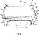
- the inner surface 22 of the cover portion 20 is spaced from the front surface 4 so as to define an inner compartment 37 which is sufficiently large to house one or more objects.
- the structure 3 and/or the lining 11 are provided with aeration holes (not shown) which put the inner compartment 37 into communication with the external environment in order to avoid formation of a depression or a counter-pressure in the inner compartment 37 when the cover portion 20 is pulled or pressed, respectively, to change the operating condition.
- the area 24 has an opening 38, which allows a user to access the inner compartment 37.
- the area 24 is constituted by a sector 39, defining at least part of the edge of the opening 38, and by a door 40, which is movable with respect to the sector 39 so as to open and close the opening 38.
- the door 40 is joined to the remaining part of the lining 11 by means of a coupling portion defining a virtual hinge.
- the opening 38 is formed in the cover portion 20 in different positions and/or with different shapes with respect to those shown in Figures 6 and 7 .
- the lining 11 comprises a closing system or a retaining system 41, which couples the door 40 to the edge of the opening 38 to keep the latter closed, and is releasable so as to be able to open the door 40.
- the system 41 is defined by one or more hinges, but other similar systems could be used (Velcro elements, press studs, hooks, magnets).
- the elements 35 form part of a frame 42, which is separate from the lining 11, is made for example of plastic or metallic material and is fixed to the cover portion 20, in a manner not shown, for example by means of seams.
- the frame 42 is arranged on the inner surface 22 or is embedded in the material of the cover portion 20.
- the elements 35 are defined by a material of the lining 11, for example by a layer of elastic material, and preferably there is no additional frame coupled to the lining 11.
- the elements 35 are defined by two elastic laminas that are applied to the sector 39 in the area 24 and are elongated in directions orthogonal to the axes 27 and 31.
- these laminas are separated from each other and are arranged on opposite sides of the opening 38.
- a single elastic lamina is provided.
- the frame 42 also comprises a stiffening element 44 (shown schematically) coupled to the area 25 in a fixed position.
- the stiffening element 44 is defined by a U-shaped frame, separated from the elements 35 and comprising at least one bar 45 that is substantially parallel to the axis 27, and therefore to direction 6 and extends throughout the length of the cover portion 20.
- the bar 45 is arranged alongside the area 23 to stiffen this area 23.
- the U-shaped frame comprises two arms 46, which project transversely from opposite ends of the bar 45 towards the portion 30, and preferably, extend throughout the depth of the area 25.
- the arms 46 have a certain bending elasticity so as to be able to perform the same bistable function as the elements 35 and cooperate with the latter in maintaining the lining 11 in the first and second operating conditions.
- the stiffening element 44 is defined by a plate.
- this plate may comprise a layer of plastic material locally stiffened by one or more metal elements.
- these metal elements are arranged in a position adjacent to the area 23 for stiffening the latter.
- the positions of the areas 24 and 25 could be mutually exchanged with respect to what is illustrated.
- the inner compartment 37 is laterally delimited by two sides 48, only one of which can be seen in this Figure.
- the sides 48 are transverse to the folding axes 27, 31 and 32 and are defined by respective lateral portions of the lining 11. These lateral portions are stretched out when the device 1 is configured in the first operating condition.
- the second operating condition Figure 2
- the lateral portions of the lining 11 are folded back on themselves, substantially halfway, when the device 1 is configured in the second operating condition.
- the sides 48 laterally define the cavity 5.
- the device 1 is specifically designed to be installed on a motor vehicle, possibly as an optional extra.
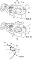
- the device 1 is transportable, for example as a box or as a bag for carrying objects or as a carrier for the transport of animals, and comprises an attachment system 50 configured so that it can be coupled in a fixed position and in a releasable manner to a corresponding attachment system (not shown) provided on the motor vehicle.
- the attachment system 50 is defined by press studs, for instance arranged on the flaps 12 and/or 13.
- other similar attachment systems for example Velcro elements, hinges, hooks, magnets
- the motor vehicle has a number of areas provided with the same attachment system, where the structure 3 can be rested and fixed, as an alternative to each other, according to the user's needs.
- the structure 3 is provided with an attachment system of the "Isofix" type to connect the device 1 in a releasable manner and in a fixed position to the rear seats of the motor vehicle.
- Figures 9 to 15 show how the device 1 may be integrated into a component of the motor vehicle, as the structure 3 forms part of this component.
- the structure 3 constitutes a part of a dashboard 51.
- one of the two sides 48 may be defined by a portion 52 of the dashboard 51.
- the structure 3 forms part of a panel 54, which covers the inside of a lateral door 55 of the motor vehicle.
- the structure 3 forms part of a panel 57, which covers a side of a boot 58 of the motor vehicle.
- the structure 3 is integrated into the components of the motor vehicle and is not detachable, therefore, the device 1 can not be used as a bag or as a transportable box.
- the lining 11 alone could be detachable and, in particular, it could be fixed interchangeably to various structures 3 forming part of different components of the motor vehicle, according to the user's needs.
- the device 1 allows for obtaining an inner compartment 37, which is totally not visible from the outside and can be fully made to disappear by pressing the lining 11 to achieve the second operating condition, in which the lining 11 itself covers the structure 3 so as to preferably perform an aesthetic function.
- the device 1 is easy to use, is relatively simple and compact and is constituted by a relatively low number of components, while the inner compartment 37 is relatively capacious.
- cover portion 20 of the lining 11 could be provided with fan-folded portions to be able to increase its extension from the portion 29 to the portion 30 when passing from the second to the first operating condition.
- the inner compartment 37 could have a shape and/or dimensions different from what is illustrated by way of example, also as a function of the position and orientation of the axes 31,32 and of the possible presence of one or more axes 27 at intermediate virtual hinges.
- the lining 11 could comprise more rigid portions in addition to flexible and foldable portions.
Applications Claiming Priority (1)
| Application Number | Priority Date | Filing Date | Title |
|---|---|---|---|
| ITUB2015A009225A ITUB20159225A1 (it) | 2015-12-29 | 2015-12-29 | Dispositivo portaoggetti configurabile |
Publications (2)
| Publication Number | Publication Date |
|---|---|
| EP3187374A1 true EP3187374A1 (fr) | 2017-07-05 |
| EP3187374B1 EP3187374B1 (fr) | 2019-01-30 |
Family
ID=55697328
Family Applications (1)
| Application Number | Title | Priority Date | Filing Date |
|---|---|---|---|
| EP16207429.8A Active EP3187374B1 (fr) | 2015-12-29 | 2016-12-29 | Dispositif porte-objet convertible |
Country Status (3)
| Country | Link |
|---|---|
| EP (1) | EP3187374B1 (fr) |
| BR (1) | BR102016030936B1 (fr) |
| IT (1) | ITUB20159225A1 (fr) |
Cited By (1)
| Publication number | Priority date | Publication date | Assignee | Title |
|---|---|---|---|---|
| FR3079482A1 (fr) * | 2018-03-30 | 2019-10-04 | Faurecia Interieur Industrie | Dispositif de rangement comprenant une paroi de fond deplacable |
Citations (4)
| Publication number | Priority date | Publication date | Assignee | Title |
|---|---|---|---|---|
| FR2562486A3 (fr) * | 1984-04-04 | 1985-10-11 | Fiat Auto Spa | Recipient porte-objets pour vehicules automobiles |
| WO1988000895A1 (fr) * | 1986-08-07 | 1988-02-11 | David John Wilkins | Boite de rangement pour voitures et son ensemble de fixation |
| EP1861289A1 (fr) | 2005-03-23 | 2007-12-05 | Faurecia Interieur Industrie | Dispositif bistable d ouverture-fermeture, et compartiment de rangement le comportant |
| WO2011126426A1 (fr) | 2010-04-08 | 2011-10-13 | Scania Cv Ab | Configuration de tablette |
-
2015
- 2015-12-29 IT ITUB2015A009225A patent/ITUB20159225A1/it unknown
-
2016
- 2016-12-29 EP EP16207429.8A patent/EP3187374B1/fr active Active
- 2016-12-29 BR BR102016030936-0A patent/BR102016030936B1/pt active IP Right Grant
Patent Citations (4)
| Publication number | Priority date | Publication date | Assignee | Title |
|---|---|---|---|---|
| FR2562486A3 (fr) * | 1984-04-04 | 1985-10-11 | Fiat Auto Spa | Recipient porte-objets pour vehicules automobiles |
| WO1988000895A1 (fr) * | 1986-08-07 | 1988-02-11 | David John Wilkins | Boite de rangement pour voitures et son ensemble de fixation |
| EP1861289A1 (fr) | 2005-03-23 | 2007-12-05 | Faurecia Interieur Industrie | Dispositif bistable d ouverture-fermeture, et compartiment de rangement le comportant |
| WO2011126426A1 (fr) | 2010-04-08 | 2011-10-13 | Scania Cv Ab | Configuration de tablette |
Cited By (1)
| Publication number | Priority date | Publication date | Assignee | Title |
|---|---|---|---|---|
| FR3079482A1 (fr) * | 2018-03-30 | 2019-10-04 | Faurecia Interieur Industrie | Dispositif de rangement comprenant une paroi de fond deplacable |
Also Published As
| Publication number | Publication date |
|---|---|
| ITUB20159225A1 (it) | 2017-06-29 |
| BR102016030936A2 (pt) | 2018-03-20 |
| EP3187374B1 (fr) | 2019-01-30 |
| BR102016030936B1 (pt) | 2022-07-19 |
Similar Documents
| Publication | Publication Date | Title |
|---|---|---|
| US8544928B2 (en) | Flexible storage compartment for vehicle interior trim | |
| RU2697337C2 (ru) | Отсек для хранения для приборной панели (варианты), приборная панель и транспортное средство, содержащее такую приборную панель | |
| US7997635B2 (en) | Bistable opening/closing device, and storage compartment comprising same | |
| CN104512349B (zh) | 用于遮阳板的显示设备固定装置 | |
| RU2678613C2 (ru) | Кресло для транспортного средства с внутренним карманом | |
| CN106476704B (zh) | 集成的座椅靠背存储部 | |
| US9937867B2 (en) | Deployable, expandable storage assembly for a motor vehicle | |
| US20150102622A1 (en) | Luggage compartment cover and vehicle with a luggage compartment cover | |
| USD832170S1 (en) | Pair of rear door panels for vehicles | |
| JP2008279891A (ja) | コンソールボックス | |
| BR102015032737A2 (pt) | montagem de acabamento de veículo com compartimento de armazenamento | |
| EP3187374B1 (fr) | Dispositif porte-objet convertible | |
| US20170042301A1 (en) | Luggage with a collapsible structure | |
| TWI233899B (en) | Mounting structure of storage box | |
| ITTO950273A1 (it) | Sedile posteriore multiposizione per un veicolo. | |
| USD832759S1 (en) | Pair of front door panels for vehicles | |
| US9180806B2 (en) | Cup holder for a motor vehicle | |
| US9987990B1 (en) | Vehicle rear cargo area structure | |
| JP2011240721A (ja) | トノカバー | |
| US8857492B2 (en) | Retractable safety cover for a rail system in a motor vehicle | |
| EP2465377A1 (fr) | Table de véhicule et boîtier correspondant dans un tableau de bord de véhicule, en particulier pour véhicules industriels ou commerciaux | |
| CN106168098A (zh) | 一种具有隐形防盗功能的平移窗 | |
| WO2016070860A3 (fr) | Bagage convertible, notamment de type sac à dos | |
| JP4737080B2 (ja) | 車両のフック配置構造 | |
| EP2048032A1 (fr) | Porte-Objet pour un véhicule |
Legal Events
| Date | Code | Title | Description |
|---|---|---|---|
| PUAI | Public reference made under article 153(3) epc to a published international application that has entered the european phase |
Free format text: ORIGINAL CODE: 0009012 |
|
| STAA | Information on the status of an ep patent application or granted ep patent |
Free format text: STATUS: THE APPLICATION HAS BEEN PUBLISHED |
|
| AK | Designated contracting states |
Kind code of ref document: A1 Designated state(s): AL AT BE BG CH CY CZ DE DK EE ES FI FR GB GR HR HU IE IS IT LI LT LU LV MC MK MT NL NO PL PT RO RS SE SI SK SM TR |
|
| AX | Request for extension of the european patent |
Extension state: BA ME |
|
| STAA | Information on the status of an ep patent application or granted ep patent |
Free format text: STATUS: REQUEST FOR EXAMINATION WAS MADE |
|
| 17P | Request for examination filed |
Effective date: 20171206 |
|
| RBV | Designated contracting states (corrected) |
Designated state(s): AL AT BE BG CH CY CZ DE DK EE ES FI FR GB GR HR HU IE IS IT LI LT LU LV MC MK MT NL NO PL PT RO RS SE SI SK SM TR |
|
| RIC1 | Information provided on ipc code assigned before grant |
Ipc: B60R 7/04 20060101AFI20180322BHEP |
|
| GRAP | Despatch of communication of intention to grant a patent |
Free format text: ORIGINAL CODE: EPIDOSNIGR1 |
|
| STAA | Information on the status of an ep patent application or granted ep patent |
Free format text: STATUS: GRANT OF PATENT IS INTENDED |
|
| INTG | Intention to grant announced |
Effective date: 20180809 |
|
| RAP1 | Party data changed (applicant data changed or rights of an application transferred) |
Owner name: FCA ITALY S.P.A. Owner name: LEVA S.P.A. A SOCIO UNICO |
|
| GRAS | Grant fee paid |
Free format text: ORIGINAL CODE: EPIDOSNIGR3 |
|
| GRAA | (expected) grant |
Free format text: ORIGINAL CODE: 0009210 |
|
| STAA | Information on the status of an ep patent application or granted ep patent |
Free format text: STATUS: THE PATENT HAS BEEN GRANTED |
|
| AK | Designated contracting states |
Kind code of ref document: B1 Designated state(s): AL AT BE BG CH CY CZ DE DK EE ES FI FR GB GR HR HU IE IS IT LI LT LU LV MC MK MT NL NO PL PT RO RS SE SI SK SM TR |
|
| REG | Reference to a national code |
Ref country code: GB Ref legal event code: FG4D |
|
| REG | Reference to a national code |
Ref country code: CH Ref legal event code: EP |
|
| REG | Reference to a national code |
Ref country code: AT Ref legal event code: REF Ref document number: 1092980 Country of ref document: AT Kind code of ref document: T Effective date: 20190215 |
|
| REG | Reference to a national code |
Ref country code: IE Ref legal event code: FG4D |
|
| REG | Reference to a national code |
Ref country code: DE Ref legal event code: R096 Ref document number: 602016009642 Country of ref document: DE |
|
| REG | Reference to a national code |
Ref country code: LT Ref legal event code: MG4D |
|
| REG | Reference to a national code |
Ref country code: NL Ref legal event code: MP Effective date: 20190130 |
|
| PG25 | Lapsed in a contracting state [announced via postgrant information from national office to epo] |
Ref country code: FI Free format text: LAPSE BECAUSE OF FAILURE TO SUBMIT A TRANSLATION OF THE DESCRIPTION OR TO PAY THE FEE WITHIN THE PRESCRIBED TIME-LIMIT Effective date: 20190130 Ref country code: NO Free format text: LAPSE BECAUSE OF FAILURE TO SUBMIT A TRANSLATION OF THE DESCRIPTION OR TO PAY THE FEE WITHIN THE PRESCRIBED TIME-LIMIT Effective date: 20190430 Ref country code: PT Free format text: LAPSE BECAUSE OF FAILURE TO SUBMIT A TRANSLATION OF THE DESCRIPTION OR TO PAY THE FEE WITHIN THE PRESCRIBED TIME-LIMIT Effective date: 20190530 Ref country code: SE Free format text: LAPSE BECAUSE OF FAILURE TO SUBMIT A TRANSLATION OF THE DESCRIPTION OR TO PAY THE FEE WITHIN THE PRESCRIBED TIME-LIMIT Effective date: 20190130 Ref country code: NL Free format text: LAPSE BECAUSE OF FAILURE TO SUBMIT A TRANSLATION OF THE DESCRIPTION OR TO PAY THE FEE WITHIN THE PRESCRIBED TIME-LIMIT Effective date: 20190130 Ref country code: ES Free format text: LAPSE BECAUSE OF FAILURE TO SUBMIT A TRANSLATION OF THE DESCRIPTION OR TO PAY THE FEE WITHIN THE PRESCRIBED TIME-LIMIT Effective date: 20190130 Ref country code: PL Free format text: LAPSE BECAUSE OF FAILURE TO SUBMIT A TRANSLATION OF THE DESCRIPTION OR TO PAY THE FEE WITHIN THE PRESCRIBED TIME-LIMIT Effective date: 20190130 Ref country code: LT Free format text: LAPSE BECAUSE OF FAILURE TO SUBMIT A TRANSLATION OF THE DESCRIPTION OR TO PAY THE FEE WITHIN THE PRESCRIBED TIME-LIMIT Effective date: 20190130 |
|
| REG | Reference to a national code |
Ref country code: AT Ref legal event code: MK05 Ref document number: 1092980 Country of ref document: AT Kind code of ref document: T Effective date: 20190130 |
|
| PG25 | Lapsed in a contracting state [announced via postgrant information from national office to epo] |
Ref country code: HR Free format text: LAPSE BECAUSE OF FAILURE TO SUBMIT A TRANSLATION OF THE DESCRIPTION OR TO PAY THE FEE WITHIN THE PRESCRIBED TIME-LIMIT Effective date: 20190130 Ref country code: RS Free format text: LAPSE BECAUSE OF FAILURE TO SUBMIT A TRANSLATION OF THE DESCRIPTION OR TO PAY THE FEE WITHIN THE PRESCRIBED TIME-LIMIT Effective date: 20190130 Ref country code: GR Free format text: LAPSE BECAUSE OF FAILURE TO SUBMIT A TRANSLATION OF THE DESCRIPTION OR TO PAY THE FEE WITHIN THE PRESCRIBED TIME-LIMIT Effective date: 20190501 Ref country code: BG Free format text: LAPSE BECAUSE OF FAILURE TO SUBMIT A TRANSLATION OF THE DESCRIPTION OR TO PAY THE FEE WITHIN THE PRESCRIBED TIME-LIMIT Effective date: 20190430 Ref country code: LV Free format text: LAPSE BECAUSE OF FAILURE TO SUBMIT A TRANSLATION OF THE DESCRIPTION OR TO PAY THE FEE WITHIN THE PRESCRIBED TIME-LIMIT Effective date: 20190130 Ref country code: IS Free format text: LAPSE BECAUSE OF FAILURE TO SUBMIT A TRANSLATION OF THE DESCRIPTION OR TO PAY THE FEE WITHIN THE PRESCRIBED TIME-LIMIT Effective date: 20190530 |
|
| PG25 | Lapsed in a contracting state [announced via postgrant information from national office to epo] |
Ref country code: EE Free format text: LAPSE BECAUSE OF FAILURE TO SUBMIT A TRANSLATION OF THE DESCRIPTION OR TO PAY THE FEE WITHIN THE PRESCRIBED TIME-LIMIT Effective date: 20190130 Ref country code: DK Free format text: LAPSE BECAUSE OF FAILURE TO SUBMIT A TRANSLATION OF THE DESCRIPTION OR TO PAY THE FEE WITHIN THE PRESCRIBED TIME-LIMIT Effective date: 20190130 Ref country code: AL Free format text: LAPSE BECAUSE OF FAILURE TO SUBMIT A TRANSLATION OF THE DESCRIPTION OR TO PAY THE FEE WITHIN THE PRESCRIBED TIME-LIMIT Effective date: 20190130 Ref country code: CZ Free format text: LAPSE BECAUSE OF FAILURE TO SUBMIT A TRANSLATION OF THE DESCRIPTION OR TO PAY THE FEE WITHIN THE PRESCRIBED TIME-LIMIT Effective date: 20190130 Ref country code: RO Free format text: LAPSE BECAUSE OF FAILURE TO SUBMIT A TRANSLATION OF THE DESCRIPTION OR TO PAY THE FEE WITHIN THE PRESCRIBED TIME-LIMIT Effective date: 20190130 Ref country code: SK Free format text: LAPSE BECAUSE OF FAILURE TO SUBMIT A TRANSLATION OF THE DESCRIPTION OR TO PAY THE FEE WITHIN THE PRESCRIBED TIME-LIMIT Effective date: 20190130 |
|
| REG | Reference to a national code |
Ref country code: DE Ref legal event code: R097 Ref document number: 602016009642 Country of ref document: DE |
|
| PG25 | Lapsed in a contracting state [announced via postgrant information from national office to epo] |
Ref country code: SM Free format text: LAPSE BECAUSE OF FAILURE TO SUBMIT A TRANSLATION OF THE DESCRIPTION OR TO PAY THE FEE WITHIN THE PRESCRIBED TIME-LIMIT Effective date: 20190130 |
|
| PLBE | No opposition filed within time limit |
Free format text: ORIGINAL CODE: 0009261 |
|
| STAA | Information on the status of an ep patent application or granted ep patent |
Free format text: STATUS: NO OPPOSITION FILED WITHIN TIME LIMIT |
|
| PG25 | Lapsed in a contracting state [announced via postgrant information from national office to epo] |
Ref country code: AT Free format text: LAPSE BECAUSE OF FAILURE TO SUBMIT A TRANSLATION OF THE DESCRIPTION OR TO PAY THE FEE WITHIN THE PRESCRIBED TIME-LIMIT Effective date: 20190130 |
|
| 26N | No opposition filed |
Effective date: 20191031 |
|
| PG25 | Lapsed in a contracting state [announced via postgrant information from national office to epo] |
Ref country code: SI Free format text: LAPSE BECAUSE OF FAILURE TO SUBMIT A TRANSLATION OF THE DESCRIPTION OR TO PAY THE FEE WITHIN THE PRESCRIBED TIME-LIMIT Effective date: 20190130 |
|
| PG25 | Lapsed in a contracting state [announced via postgrant information from national office to epo] |
Ref country code: TR Free format text: LAPSE BECAUSE OF FAILURE TO SUBMIT A TRANSLATION OF THE DESCRIPTION OR TO PAY THE FEE WITHIN THE PRESCRIBED TIME-LIMIT Effective date: 20190130 |
|
| REG | Reference to a national code |
Ref country code: CH Ref legal event code: PL |
|
| REG | Reference to a national code |
Ref country code: BE Ref legal event code: MM Effective date: 20191231 |
|
| PG25 | Lapsed in a contracting state [announced via postgrant information from national office to epo] |
Ref country code: MC Free format text: LAPSE BECAUSE OF FAILURE TO SUBMIT A TRANSLATION OF THE DESCRIPTION OR TO PAY THE FEE WITHIN THE PRESCRIBED TIME-LIMIT Effective date: 20190130 |
|
| PG25 | Lapsed in a contracting state [announced via postgrant information from national office to epo] |
Ref country code: IE Free format text: LAPSE BECAUSE OF NON-PAYMENT OF DUE FEES Effective date: 20191229 Ref country code: LU Free format text: LAPSE BECAUSE OF NON-PAYMENT OF DUE FEES Effective date: 20191229 |
|
| PG25 | Lapsed in a contracting state [announced via postgrant information from national office to epo] |
Ref country code: LI Free format text: LAPSE BECAUSE OF NON-PAYMENT OF DUE FEES Effective date: 20191231 Ref country code: CH Free format text: LAPSE BECAUSE OF NON-PAYMENT OF DUE FEES Effective date: 20191231 Ref country code: BE Free format text: LAPSE BECAUSE OF NON-PAYMENT OF DUE FEES Effective date: 20191231 |
|
| PG25 | Lapsed in a contracting state [announced via postgrant information from national office to epo] |
Ref country code: CY Free format text: LAPSE BECAUSE OF FAILURE TO SUBMIT A TRANSLATION OF THE DESCRIPTION OR TO PAY THE FEE WITHIN THE PRESCRIBED TIME-LIMIT Effective date: 20190130 |
|
| PG25 | Lapsed in a contracting state [announced via postgrant information from national office to epo] |
Ref country code: HU Free format text: LAPSE BECAUSE OF FAILURE TO SUBMIT A TRANSLATION OF THE DESCRIPTION OR TO PAY THE FEE WITHIN THE PRESCRIBED TIME-LIMIT; INVALID AB INITIO Effective date: 20161229 Ref country code: MT Free format text: LAPSE BECAUSE OF FAILURE TO SUBMIT A TRANSLATION OF THE DESCRIPTION OR TO PAY THE FEE WITHIN THE PRESCRIBED TIME-LIMIT Effective date: 20190130 |
|
| GBPC | Gb: european patent ceased through non-payment of renewal fee |
Effective date: 20201229 |
|
| PG25 | Lapsed in a contracting state [announced via postgrant information from national office to epo] |
Ref country code: GB Free format text: LAPSE BECAUSE OF NON-PAYMENT OF DUE FEES Effective date: 20201229 |
|
| PG25 | Lapsed in a contracting state [announced via postgrant information from national office to epo] |
Ref country code: MK Free format text: LAPSE BECAUSE OF FAILURE TO SUBMIT A TRANSLATION OF THE DESCRIPTION OR TO PAY THE FEE WITHIN THE PRESCRIBED TIME-LIMIT Effective date: 20190130 |
|
| PGFP | Annual fee paid to national office [announced via postgrant information from national office to epo] |
Ref country code: IT Payment date: 20221122 Year of fee payment: 7 |
|
| PGFP | Annual fee paid to national office [announced via postgrant information from national office to epo] |
Ref country code: FR Payment date: 20231122 Year of fee payment: 8 Ref country code: DE Payment date: 20231121 Year of fee payment: 8 |