EP3187349A1 - Tailgate for vehicle - Google Patents
Tailgate for vehicle Download PDFInfo
- Publication number
- EP3187349A1 EP3187349A1 EP15307173.3A EP15307173A EP3187349A1 EP 3187349 A1 EP3187349 A1 EP 3187349A1 EP 15307173 A EP15307173 A EP 15307173A EP 3187349 A1 EP3187349 A1 EP 3187349A1
- Authority
- EP
- European Patent Office
- Prior art keywords
- wall
- tailgate
- outer panel
- bridge
- vehicle
- Prior art date
- Legal status (The legal status is an assumption and is not a legal conclusion. Google has not performed a legal analysis and makes no representation as to the accuracy of the status listed.)
- Granted
Links
Images


Classifications
-
- B—PERFORMING OPERATIONS; TRANSPORTING
- B60—VEHICLES IN GENERAL
- B60J—WINDOWS, WINDSCREENS, NON-FIXED ROOFS, DOORS, OR SIMILAR DEVICES FOR VEHICLES; REMOVABLE EXTERNAL PROTECTIVE COVERINGS SPECIALLY ADAPTED FOR VEHICLES
- B60J5/00—Doors
- B60J5/10—Doors arranged at the vehicle rear
- B60J5/101—Doors arranged at the vehicle rear for non-load transporting vehicles, i.e. family cars including vans
- B60J5/107—Doors arranged at the vehicle rear for non-load transporting vehicles, i.e. family cars including vans constructional details, e.g. about door frame, panels, materials used, reinforcements
-
- B—PERFORMING OPERATIONS; TRANSPORTING
- B60—VEHICLES IN GENERAL
- B60J—WINDOWS, WINDSCREENS, NON-FIXED ROOFS, DOORS, OR SIMILAR DEVICES FOR VEHICLES; REMOVABLE EXTERNAL PROTECTIVE COVERINGS SPECIALLY ADAPTED FOR VEHICLES
- B60J10/00—Sealing arrangements
- B60J10/30—Sealing arrangements characterised by the fastening means
- B60J10/34—Sealing arrangements characterised by the fastening means using adhesives
-
- B—PERFORMING OPERATIONS; TRANSPORTING
- B60—VEHICLES IN GENERAL
- B60Q—ARRANGEMENT OF SIGNALLING OR LIGHTING DEVICES, THE MOUNTING OR SUPPORTING THEREOF OR CIRCUITS THEREFOR, FOR VEHICLES IN GENERAL
- B60Q1/00—Arrangement of optical signalling or lighting devices, the mounting or supporting thereof or circuits therefor
- B60Q1/26—Arrangement of optical signalling or lighting devices, the mounting or supporting thereof or circuits therefor the devices being primarily intended to indicate the vehicle, or parts thereof, or to give signals, to other traffic
- B60Q1/30—Arrangement of optical signalling or lighting devices, the mounting or supporting thereof or circuits therefor the devices being primarily intended to indicate the vehicle, or parts thereof, or to give signals, to other traffic for indicating rear of vehicle, e.g. by means of reflecting surfaces
-
- B—PERFORMING OPERATIONS; TRANSPORTING
- B60—VEHICLES IN GENERAL
- B60Q—ARRANGEMENT OF SIGNALLING OR LIGHTING DEVICES, THE MOUNTING OR SUPPORTING THEREOF OR CIRCUITS THEREFOR, FOR VEHICLES IN GENERAL
- B60Q1/00—Arrangement of optical signalling or lighting devices, the mounting or supporting thereof or circuits therefor
- B60Q1/26—Arrangement of optical signalling or lighting devices, the mounting or supporting thereof or circuits therefor the devices being primarily intended to indicate the vehicle, or parts thereof, or to give signals, to other traffic
- B60Q1/2619—Arrangement of optical signalling or lighting devices, the mounting or supporting thereof or circuits therefor the devices being primarily intended to indicate the vehicle, or parts thereof, or to give signals, to other traffic built in the vehicle body
-
- B—PERFORMING OPERATIONS; TRANSPORTING
- B60—VEHICLES IN GENERAL
- B60Q—ARRANGEMENT OF SIGNALLING OR LIGHTING DEVICES, THE MOUNTING OR SUPPORTING THEREOF OR CIRCUITS THEREFOR, FOR VEHICLES IN GENERAL
- B60Q1/00—Arrangement of optical signalling or lighting devices, the mounting or supporting thereof or circuits therefor
- B60Q1/26—Arrangement of optical signalling or lighting devices, the mounting or supporting thereof or circuits therefor the devices being primarily intended to indicate the vehicle, or parts thereof, or to give signals, to other traffic
- B60Q1/2619—Arrangement of optical signalling or lighting devices, the mounting or supporting thereof or circuits therefor the devices being primarily intended to indicate the vehicle, or parts thereof, or to give signals, to other traffic built in the vehicle body
- B60Q1/2638—Positioning the device housing by indexing means separate from the fastening means, e.g. pins, rails
-
- B—PERFORMING OPERATIONS; TRANSPORTING
- B60—VEHICLES IN GENERAL
- B60Y—INDEXING SCHEME RELATING TO ASPECTS CROSS-CUTTING VEHICLE TECHNOLOGY
- B60Y2410/00—Constructional features of vehicle sub-units
- B60Y2410/12—Production or manufacturing of vehicle parts
- B60Y2410/125—Bounded parts
Definitions
- the invention relates to the technical filed of tailgates for vehicle, particularly plastic tailgates, which often comprise optical units.
- a tailgate for vehicle usually comprises an inner panel as a structural part and an outer panel as an appearance skin. Sometimes it further comprises optical units, also named rear lights, disposed on right and left ends of the tailgate.
- tailgates vary a lot, depending on different externally-visible style shapes of the whole vehicle, so does the appearance of rear lights which are integrated thereon. Therefore, on a tailgate for vehicle in question are provided housings to receive optical units and their shapes should be adapted at least both as an integration and fixation interface of the optical units and also be consistent to realize the external style shapes of the tailgate.
- the robot 3 has to apply glue on the outer panel 2 with an angle normal to the inside face (thus normal to the seal path itself) so as to move along the inside face of the outer panel with a number of parallel travels to apply glue bead as required. Then the inner and outer panels, with the seal path made of glue on the inside face of the outer panel, are bonded together by being pressed against each other in a main bonding direction of the tailgate so as to avoid to spread the glue. This main bonding direction is normal to the global form of the tailgate for vehicles.
- Figure 1 illustrates the main bonding direction as the dotted line 5, it should be understood that the direction indicated by the dotted line 5 is illustrative, given only as an example and not limitative at all, becasue
- Figure 1 is a partial view of an exemplary tailgate for vehicle and only schematically illustrates one exemplary optical housing located at one side of the tailgate.
- the respective housing's upper walls formed by the outer and inner panels are often oriented in such a way (almost parallel, or even worse in an undercut position, with respect to the main bonding direction) that
- the invention seeks thus to provide a tailgate for vehicle wherein the bonding sealing of the panels forming the tailgate is facilitated and efficient, particularly around the optical unit housing.
- One subject of the invention lies in providing a tailgate for vehicle, comprising:
- said bridge which provides an additional surface for covering such an inaccessible hollow cavity
- the inside face of the outer panel to be bonded to the inner panel is easily accessible by a robot and its applicator: for bonding the outer panel with the inner panel, it is no longer necessary to apply glue on walls of a deep corner with right or sharp or acute angle therebetween.
- the proper pressing (see above) of the outer and inner panels against each other in the main bonding direction is easier and more reliable. In other words, it can be avoided to suffer a bonding surface, around the optical housing, which is formed by corners of shapes with an angle less than or about 90°, in other words an acute angle or an almost right angle.
- the bonding interface between the inner and outer panels can be flatter and smoother, that is to say, with gentler slopes, and that deep enough optical housings can be still formed on the outer panel.
- the surfaces to be bonded of the inner and outer panels will be in a better contact with each other all along the main bonding direction.
- a seal path will be continuous with sufficient glue and lead to a proper waterproofness of the tailgate for vehicle, especially in the taillight area.
- Another subject of the invention lies in providing a process for molding an outer panel for a tailgate for vehicle according to any embodiment as mentioned above, wherein a movable slider is built and used in a mold to create a hollow cavity delimited by the appearance wall, the edge wall and the bridge wall. Such a hollow cavity, which is no longer naturally demoldable as being covered by the bridge wall, is thus easier to be molded.
- This movable slider is a retractable core for the case of injection molding.
- tailgate for vehicle as obtained allows more design freedom and manufacturing feasibility to achieve a watertight condition in the assembling process of the outer and inner panels.
- FIG. 2 schematically illustrates an embodiment of a tailgate 12 for vehicle according to an embodiment.
- This tailgate for vehicle is designed to have optical housings 14 for receiving taillights (or rear lights), which are for example arranged symmetrically at both lateral sides of the tailgate in this embodiment.
- the optical housings 14 located on the tailgate can be very varied in shapes, for example is deep with steep walls which forms acute or almost right angles with the bottom of the housing or with the outside surface of the tailgate (which is visible from outside of the vehicle).
- the tailgate 12 comprises an inner panel 1 and an outer panel 2.
- the inner panel 1 is partially shown in Figure 2 .
- the outer panel 2 is schematically shown in Figure 2 .
- the inner panel 1 is a structural part of the vehicle while the outer panel 2 is an appearance part.
- the inner panel 1 is a frame of the tailgate made of thermoplastic (such as PP) or of thermoset plastic (preferably SMC, that is, Sheet Molding Compound) and the outer panel 2 is the outside skin of the tailgate made of thermoplastic material, such as PP.
- the inner panel and outer panel normally have complex three-dimensional shapes, which are surely not limited to what schematically shown in the figures.
- the outer panel 2 comprises, among others, an appearance wall 21 and an edge wall 22, as shown in Figure 3 .
- the edge wall 22 is adjacent to the appearance wall 21 and takes part in delimiting the housing 14 for receiving the optical unit.
- the outer panel 2 can further comprise a bottom wall 24, which forms the bottom of the housing 14, that is to say, the bottom wall 24 also takes part in delimiting the housing 14.
- the other walls of the housing which are not visible in the view of Figure 3 are not described here for sake of succinctness.
- the edge wall 22 is quite normal to the appearance wall 21, and the bottom wall 24 is quite normal to the edge wall 22.
- the outer panel 2 further comprises, on its inside face, a bridge wall 23, designed as a bridge between the upper edge wall 22 and the appearance wall 21 for convering the volume therebetween.
- the bridge wall 23 also serves as a part of a bonding surface B to be bonded to a surface A of the inner panel 1, wherein the bonding of the surfaces A and B is preferably realized by means of gluing.
- the gluing is advantageously used for sealing the volume between the two panels to keep it dry, so as to protect the electrical wiring and components located between the two panels, inside the tailgate from being affected with damp.
- the glue is applied by a robot 3 (as shown in Figure 4a ), often on the inside face of the outer panel 2, so as to obtain a seal path 4 formed by glue bead (as shown in Figure 4b ) which is continuous and waterproof.
- the seal path preferably forms a closed loop on its own.
- the bridge wall 23 forms an obtuse angle 26 with the bottom wall 24, instead of the nearly right angle between the edge wall 22 and the bottom wall 24.
- the surface A of the inner panel 1, which is to be bonded to the bonding surface B of the outer panel 2 forms an obtuse angle 27 preferably almost equal to the obtuse angle 26 formed by the bridge wall 23 and the bottom wall 24 of the outer panel 2.
- the obtuse angles 26 and 27 are viewed from the outside of the tailgate and toward the inside thereof.
- the obtuse angle 26 of the outer panel 2 is defined by the position of the bridge wall 23 and can be up to nearly 180°, as well as the obtuse angle 27 of the inner panel 1, in other words, the bonding surface B of the outer panel 2 and the surface A of the inner panel 1 to be bonded to the bonding surface B of the outer panel 2 is flatter at this taillight area by means of the bridge wall 23. It should be understood that a small fabrication tolerance may be present to cause that the two obtuse angles 26, 27 are not precisely equal to each other.
- the appearance wall 21, the edge wall 22 and the bridge wall 23 delimit a hollow cavity 25.
- the form of the lateral section of the hollow cavity 25 along the XZ plane of the vehicle is not limited to the example shown in Figures 3 and 4 , but is varied as a function of the shape of the housing and the style of the tailgate.
- the hollow cavity 25 is closed on at least one end by an end wall 28 which is preferably located on the lateral side of the tailgate, so that entry of water between the inner and the outer panels is avoided. Thus the end wall 28 is visible from outside of the vehicle.
- the appearance wall 21 is the only wall visible from outside of the vehicle when the optical unit, like a taillight, is well installed in place in the housing 14.
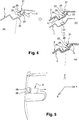
- Figure 4 schematically illustrates in sequence the main steps of assembling the outer and inner panels 1 and 2 for manufacturing the tailgate for vehicle as mentioned above (in the figure the dotted line indicates the main bonding direction of the two panels as mentioned above):
- the process for manufacturing the tailgate for vehicle consists of molding the outer panel 2 by means of a movable slider 6, which is built and used in the mold to create the hollow cavity 25 delimited by the appearance wall 21, the edge wall 22 and the bridge wall 23 of the outer panel 2. It is noted that without the bridge wall 23, the volume between the edge wall 22 and the appearance wall 21 is naturally demoldable. Such volume becomes naturally non-demoldable after being covered by the bridge wall 23 and thus the movable slider is needed.
- the movable slider is a retractable core. The slider can be easily removed through another non-closed end which is opposite to the end closed by the end wall 28 according to an embodiment.
Landscapes
- Engineering & Computer Science (AREA)
- Mechanical Engineering (AREA)
- Lighting Device Outwards From Vehicle And Optical Signal (AREA)
- Body Structure For Vehicles (AREA)
- Moulds For Moulding Plastics Or The Like (AREA)
Abstract
Description
- The invention relates to the technical filed of tailgates for vehicle, particularly plastic tailgates, which often comprise optical units.
- A tailgate for vehicle usually comprises an inner panel as a structural part and an outer panel as an appearance skin. Sometimes it further comprises optical units, also named rear lights, disposed on right and left ends of the tailgate.
- The appearance of tailgates varies a lot, depending on different externally-visible style shapes of the whole vehicle, so does the appearance of rear lights which are integrated thereon. Therefore, on a tailgate for vehicle in question are provided housings to receive optical units and their shapes should be adapted at least both as an integration and fixation interface of the optical units and also be consistent to realize the external style shapes of the tailgate.
- In addition to the need for aesthetic appearance, there is a strong need for the internal waterproofness (or tightness) of the tailgate for vehicle whose internal volume includes electrical devices. To this end, it is known to ensure waterproofness of the tailgate by means of a
continuous seal path 4 between aninner panel 1 and anouter panel 2 which form the tailgate and delimit at least oneoptical housing 14 together, as shown inFigure 1 . This seal path, which is often made of glue, is generally applied on the inside face of the outer panel and also used for bonding the outer panel with the inner panel together. Due to constraints of mass production of vehicles, the glue forming the seal path is usually deposited by arobot 3. As shown inFigure 1a , for the purpose of having a correct seal path, therobot 3 has to apply glue on theouter panel 2 with an angle normal to the inside face (thus normal to the seal path itself) so as to move along the inside face of the outer panel with a number of parallel travels to apply glue bead as required. Then the inner and outer panels, with the seal path made of glue on the inside face of the outer panel, are bonded together by being pressed against each other in a main bonding direction of the tailgate so as to avoid to spread the glue. This main bonding direction is normal to the global form of the tailgate for vechicle. AlthoughFigure 1 illustrates the main bonding direction as thedotted line 5, it should be understood that the direction indicated by thedotted line 5 is illustrative, given only as an example and not limitative at all, becasueFigure 1 is a partial view of an exemplary tailgate for vehicle and only schematically illustrates one exemplary optical housing located at one side of the tailgate. - However, due to the main bonding direction and due to the shape of the optical housing area which includes right or sharp or acute angles, it could be almost impossible for a single-axis robot to apply glue, particularly in corners located on the inside face of the outer panel just around the optic units. Alternatively, using a robot with a smaller applicator or with multi-axis could be helpful in some cases but not in all cases nor allows to apply glue normally to the seal path.
- Moreover, the respective housing's upper walls formed by the outer and inner panels are often oriented in such a way (almost parallel, or even worse in an undercut position, with respect to the main bonding direction) that
- at first does not allow an easy fitting while bringing one panel to the other to their final assembled position along the main bonding direction;
- then makes it difficult or impossible to apply a proper pressure (by "proper pressure", it is meant a pressure which is almost constant over the whole seal path whatever the 3D shape of the taillight area) for assembling the two panels on the glue bead applied on a portion of the inside face on the outer panel, because the pressure is applied mainly in a direction perpendicular to the rest of the contour/perimeter of the whole tailgate which is more or less planer than this local portion.
- Insufficient or even no pressure applied on the glue bead between the two panels could lead to a discontinuous sealing and water leakage inside the tailgate.
- The invention seeks thus to provide a tailgate for vehicle wherein the bonding sealing of the panels forming the tailgate is facilitated and efficient, particularly around the optical unit housing.
- One subject of the invention lies in providing a tailgate for vehicle, comprising:
- an inner panel,
- an outer panel including an appearance wall and an edge wall adjacent to the appearance wall and taking part in delimiting a housing for receiving an optical unit,
- Thanks to said bridge which provides an additional surface for covering such an inaccessible hollow cavity, the inside face of the outer panel to be bonded to the inner panel is easily accessible by a robot and its applicator: for bonding the outer panel with the inner panel, it is no longer necessary to apply glue on walls of a deep corner with right or sharp or acute angle therebetween. Furthermore, the proper pressing (see above) of the outer and inner panels against each other in the main bonding direction is easier and more reliable. In other words, it can be avoided to suffer a bonding surface, around the optical housing, which is formed by corners of shapes with an angle less than or about 90°, in other words an acute angle or an almost right angle.
- Therefore, it is advantageous that the bonding interface between the inner and outer panels can be flatter and smoother, that is to say, with gentler slopes, and that deep enough optical housings can be still formed on the outer panel. This significantly improves the assembly process of the two panels by facilitating the access of a robot used for bonding for example by gluing and the proper pressing of the two panels against each other in the main bonding direction, and in the meantime allows a very varied style of the tailgate for vehicle. With this adaptation, the surfaces to be bonded of the inner and outer panels will be in a better contact with each other all along the main bonding direction. Furthermore, it is guaranteed that a seal path will be continuous with sufficient glue and lead to a proper waterproofness of the tailgate for vehicle, especially in the taillight area.
- The tailgate may also preferably include at least one of the following features, separately or in combination.
- The bridge wall located on the inside face of the outer panel forms an obtuse angle with the bottom wall of the housing for receiving the optical unit.
- The inner panel to be bonded to the outer panel presents an obtuse angle almost equal to the obtuse angle formed by the bridge wall of the outer panel and the bottom wall of the housing receiving the optical unit. It is noted that the obtuse angle of the outer panel is decided by the position of the bridge wall and can be up to nearly 180°, as well as the obtuse angle of the inner panel. The closer the obtuse angle is to 180°, the flatter the bonding interface between the outer panel and the inner panel at this local taillight area is. Thus, it is easier to properly press and assembly the outer and inner panels and the bonding therebetween is more reliable.
- The housing for receiving the optical unit is located inside the perimeter of a continuous seal path which is formed on the inside face of the outer panel: this insures that the electrical wiring and components of the optical unit are inside the dry volume between the two panels. In other words, the continuous seal path of the tailgate defines a watertight zone which includes, and thus protects, the housing for receiving the optical unit.
- The appearance wall, the edge wall and the bridge wall delimit a hollow cavity. Thus, the outer panel of the tailgate is quite innovative in that it forms by itself a hollow cavity. The shape of the hollow cavity can be varied as a function of the shape of the housing receiving the optical unit and the visible appearance of the vehicle as required.- The hollow cavity of the outer panel defines a volume with an approximately triangular transversal (or lateral) section, along the XZ plane of the vehicle, and thus enhances the mechanical resistance of the hollow cavity. However many other shapes are possible, depending of the design of the tailgate.
- The hollow cavity is closed on one end by an end wall which is preferably disposed on the most lateral side of the tailgate. Thus, entry of water between the inner and the outer panels is avoided and furthermore there is no non-aesthetic part visible from outside of the tailgate.
- The assembly of the inner panel with the outer panel is realized by gluing and pressing, wherein the gluing is preferably waterproof gluing by means of a robot. Advantageously, since the bonding interface between the inner panel and the outer panel can be flatter and smoother, a robot used to apply glue can enter and move along the whole inside face on the outer panel more easily and smoothly. This gives more freedom for the choice of the robot because it is no longer necessary to use a robot with smaller applicator or multi-axis. As a result, the glue can be advantageously deposited to be continuous and sufficient. Furthermore, it is easier for the outer panel and the inner panel to approach each other and to be fitted together. Then it allows to propoerly press the two panels against each other in the main bonding direction, in other words, it is capable of applying a pressure to the glue bead on the inside face of the outer panel in the main bonding direction which is almost constant over the whole seal path regardless of the complexity of the 3D shape the taillight area, so as to bond the two panels firmly with sufficient glue distributed therebetween as required. The waterproofness of the tailgate is thus guaranteed.
- The bridge wall preferably forms a bridge between the edge wall and the inside surface of a styling line made on the appearance wall. In other words, the bridge wall is connected to the appearance wall in the area of a styling line. A styling line of the tailgate has usually to be understood as a line forming an angle or a visual rupture on the outside surface of the tailgate, for example due to a folding of the surface. By connecting the bridge wall to the appearance wall in the area of a styling line, some defects of the surface of the tailgate for vehicle due to the joining between the bridge wall and the appearance wall, for example shrink marks, are not visible from outside, as they are shaded or masked by the styling line. Thus it is advantageous to make the bridge wall join to the appearance wall behind a styling line thereon where the appearance wall has a change in angle (usually by folding), so that at lease some of the defects can be less easily seen from the outside of the vehicle.
- Another subject of the invention lies in providing a process for molding an outer panel for a tailgate for vehicle according to any embodiment as mentioned above, wherein a movable slider is built and used in a mold to create a hollow cavity delimited by the appearance wall, the edge wall and the bridge wall. Such a hollow cavity, which is no longer naturally demoldable as being covered by the bridge wall, is thus easier to be molded. This movable slider is a retractable core for the case of injection molding.
- It is understood that the tailgate for vehicle as obtained allows more design freedom and manufacturing feasibility to achieve a watertight condition in the assembling process of the outer and inner panels.
- The accompanying drawings are used to schematically illustrate presently preferred but non-limiting exemplary embodiments of the present invention. The above and other advantages and features of the invention will become more apparent and the invention will be better understood by reading the following detailed description with reference to the accompanying drawings. It should be understood that all the directions, shapes, angles, dimensions including lengths and thicknesses, distances and so on shown in these drawings are given only for the purpose of illustrating and the invention is not limited to them. In the accompanying drawings:
-
Figure 1 schematically illustrates the principal steps for assembling an inner panel with an outer panel for forming a tailgate for vehicle according to the prior art; -
Figure 2 is an outside view of a tailgate for vehicle according to an embodiment of the invention, viewed from the rear of a vehicle, wherein the XYZ directions of the vehicle are schematically illustrated; -
Figure 3 is a schematic lateral exploded section (along the XZ plane) of the taillight area circled inFigure 2 ; -
Figure 4 schematically illustrates the principal steps for assembling the inner panel with the outer panel for forming the tailgate ofFigure 2 ; and -
Figure 5 is a schematic perspective view, from the inside face of the inner panel, showing the withdrawing of a movable slider when molding the outer panel of the tailgate ofFigure 2 . - Preferred embodiments of a tailgate for vehicle as described above are now described with reference to the accompanying drawings, in which same references are used for similar elements having similar functions.
-
Figure 2 schematically illustrates an embodiment of atailgate 12 for vehicle according to an embodiment. This tailgate for vehicle is designed to haveoptical housings 14 for receiving taillights (or rear lights), which are for example arranged symmetrically at both lateral sides of the tailgate in this embodiment. As a result of very varied styles between vehicles, theoptical housings 14 located on the tailgate can be very varied in shapes, for example is deep with steep walls which forms acute or almost right angles with the bottom of the housing or with the outside surface of the tailgate (which is visible from outside of the vehicle). - The
tailgate 12 comprises aninner panel 1 and anouter panel 2. Theinner panel 1 is partially shown inFigure 2 . Theouter panel 2 is schematically shown inFigure 2 . Preferably, theinner panel 1 is a structural part of the vehicle while theouter panel 2 is an appearance part. For example, theinner panel 1 is a frame of the tailgate made of thermoplastic (such as PP) or of thermoset plastic (preferably SMC, that is, Sheet Molding Compound) and theouter panel 2 is the outside skin of the tailgate made of thermoplastic material, such as PP. The inner panel and outer panel normally have complex three-dimensional shapes, which are surely not limited to what schematically shown in the figures. - Now reference is made to
figures 3 and4 . Theouter panel 2 comprises, among others, anappearance wall 21 and anedge wall 22, as shown inFigure 3 . Theedge wall 22 is adjacent to theappearance wall 21 and takes part in delimiting thehousing 14 for receiving the optical unit. Theouter panel 2 can further comprise abottom wall 24, which forms the bottom of thehousing 14, that is to say, thebottom wall 24 also takes part in delimiting thehousing 14. The other walls of the housing which are not visible in the view ofFigure 3 are not described here for sake of succinctness. In this embodiment, theedge wall 22 is quite normal to theappearance wall 21, and thebottom wall 24 is quite normal to theedge wall 22. We can say that here theedge wall 22 forms a nearly right angle with thebottom wall 24 which is normally slightly bigger than 90° so as to facilitate the demolding of the panel and the installation in place of the optical unit, and forms a right or sharp or acute angle with theappearance wall 21. - The
outer panel 2 further comprises, on its inside face, abridge wall 23, designed as a bridge between theupper edge wall 22 and theappearance wall 21 for convering the volume therebetween. Thebridge wall 23 also serves as a part of a bonding surface B to be bonded to a surface A of theinner panel 1, wherein the bonding of the surfaces A and B is preferably realized by means of gluing. The gluing is advantageously used for sealing the volume between the two panels to keep it dry, so as to protect the electrical wiring and components located between the two panels, inside the tailgate from being affected with damp. Usually, the glue is applied by a robot 3 (as shown inFigure 4a ), often on the inside face of theouter panel 2, so as to obtain aseal path 4 formed by glue bead (as shown inFigure 4b ) which is continuous and waterproof. The seal path preferably forms a closed loop on its own. - As it can be seen from
Figures 3 and4 , thebridge wall 23 forms anobtuse angle 26 with thebottom wall 24, instead of the nearly right angle between theedge wall 22 and thebottom wall 24. Moreover, the surface A of theinner panel 1, which is to be bonded to the bonding surface B of theouter panel 2, forms anobtuse angle 27 preferably almost equal to theobtuse angle 26 formed by thebridge wall 23 and thebottom wall 24 of theouter panel 2. Here, it should be understood that theobtuse angles obtuse angle 26 of theouter panel 2 is defined by the position of thebridge wall 23 and can be up to nearly 180°, as well as theobtuse angle 27 of theinner panel 1, in other words, the bonding surface B of theouter panel 2 and the surface A of theinner panel 1 to be bonded to the bonding surface B of theouter panel 2 is flatter at this taillight area by means of thebridge wall 23. It should be understood that a small fabrication tolerance may be present to cause that the twoobtuse angles - Advantageously, the
appearance wall 21, theedge wall 22 and thebridge wall 23 delimit ahollow cavity 25. It should be understood that the form of the lateral section of thehollow cavity 25 along the XZ plane of the vehicle is not limited to the example shown inFigures 3 and4 , but is varied as a function of the shape of the housing and the style of the tailgate. Also, as can be seen fromfigure 5 , thehollow cavity 25 is closed on at least one end by an end wall 28 which is preferably located on the lateral side of the tailgate, so that entry of water between the inner and the outer panels is avoided. Thus the end wall 28 is visible from outside of the vehicle. - It is also noted that among the
walls outer panel 2, theappearance wall 21 is the only wall visible from outside of the vehicle when the optical unit, like a taillight, is well installed in place in thehousing 14. - According to an embodiment, the
bridge wall 23 forms a bridge between theedge wall 22 and a styling line on theappearance wall 21, the styling line corresponding usually to a folding of theappearance wall 21, creating a line forming an angle or a visual rupture on the outside surface of the tailgate. Particularly, the joining of thebridge wall 23 to theappearance wall 21 possibly creates defects on the surface of thetailgate 12 for vehicle, such as shrink marks and so on. Thus it is advantageous to make thebridge wall 23 join to theappearance wall 21 behind a styling line, so that at least certain of the defects are less easily visible from the outside of the vehicle as being shaded by the outstanding styling line. - A process for manufacturing the
tailgate 12 for vehicle is now described, with reference toFigures 4 and 5 . -
Figure 4 schematically illustrates in sequence the main steps of assembling the outer andinner panels - applying material for bonding such as glue on the bonding surface B (the inside face) of the
outer panel 2 by means of the gluingrobot 3, wherein it can be seen that therobot 3 can access to and move along the bonding surface B quite easily and smoothly because the bonding surface B presents fewer steep slope(s) (Figure 4a ); - moving the
robot 3 all along the bonding surface B of theouter panel 2 in a number of travels, until acontinuous seal path 4 for bonding is properly formed (Figure 4b ); - then pressing the
outer panel 2 and theinner panel 1 with sufficient pressure mainly in the tailgate bonding direction i.e. the main bonding direction as mentioned above, so as to assemble the two panels together with a good tightness therebetween (Figure 4c ). - As can be seen from
Figure 5 , the process for manufacturing the tailgate for vehicle according to an embodiment consists of molding theouter panel 2 by means of amovable slider 6, which is built and used in the mold to create thehollow cavity 25 delimited by theappearance wall 21, theedge wall 22 and thebridge wall 23 of theouter panel 2. It is noted that without thebridge wall 23, the volume between theedge wall 22 and theappearance wall 21 is naturally demoldable. Such volume becomes naturally non-demoldable after being covered by thebridge wall 23 and thus the movable slider is needed. For the injection molding, the movable slider is a retractable core. The slider can be easily removed through another non-closed end which is opposite to the end closed by the end wall 28 according to an embodiment. - So far, the invention has been described by means of a limited number of embodiments. However, it should be understood that without prejudice to the underlying principles of the invention, the details and the embodiments may vary, even appreciably, with respect to what has been described by way of example only, without departing from the scope of the invention as defined by the annexed claims.
Claims (11)
- A tailgate for vehicle, characterized in that it comprises- an inner panel (1),- an outer panel (2) including an appearance wall (21) and an edge wall (22) adjacent to the appearance wall (21) and taking part in delimiting a housing for receiving an optical unit,wherein the outer panel further includes a bridge wall (23), located on the inside face of the outer panel, forming a bridge between the edge wall (22) and the appearance wall (21) and serving as a part of a bonding interface between the outer panel and the inner panel.
- The tailgate for vehicle according to claim 1, wherein the bridge wall (23) of the outer panel (2) forms an obtuse angle (26) with a bottom wall (24) of the housing for receiving the optical unit, the obtuse angle (26) of the outer panel (2) is viewed from the outside of the vehicle.
- The tailgate for vehicle according to the preceding claim, wherein a surface (A) of the inner panel (1) which is bonded to a bonding surface (B) of the outer panel (2) forms an obtuse angle (27) which is almost equal to the obtuse angle formed by the bridge wall (23) of the outer panel (2) and the bottom wall (24) of the housing for receiving the optical unit, the obtuse angle (27) of the inner panel (1) is viewed from the outside of the vehicle.
- The tailgate for vehicle according to any one of the preceding claims, the housing for receiving the optical unit is located inside the perimeter of a continuous seal path, which is formed on the bonding surface of the outer panel by the bonding.
- The tailgate for vehicle according to any one of the preceding claims, wherein the appearance wall (21), the edge wall (22) and the bridge wall (23) delimit a hollow cavity (25).
- The tailgate for vehicle according to claim 5, wherein the hollow cavity (25) is closed on one end by an end wall (28) which is preferably disposed on the most lateral side of the tailgate.
- The tailgate for vehicle according to any one of the preceding claims, wherein the bonding of the inner panel (1) and the outer panel (2) is realized by gluing and pressing.
- The tailgate for vehicle according to the preceding claim, wherein the gluing is waterproof gluing by means of a robot.
- The tailgate for vehicle according to any one of the preceding claims, wherein the bridge wall (23) forms a bridge between the edge wall (22) and the inside surface of a styling line made on the appearance wall (21).
- A process for molding an outer panel (2) for a tailgate for vehicle according to any one of the preceding claims, wherein a movable slider (6) is built and used in a mold to create a naturally non-demoldable hollow cavity (25) delimited by the appearance wall (21), the edge wall (22) and the bridge wall (23).
- The process according to the preceding claim, wherein the movable slider (6) is a retractable core for injection molding.
Priority Applications (9)
| Application Number | Priority Date | Filing Date | Title |
|---|---|---|---|
| ES15307173T ES2744468T3 (en) | 2015-12-30 | 2015-12-30 | Vehicle gate |
| EP15307173.3A EP3187349B1 (en) | 2015-12-30 | 2015-12-30 | Tailgate for vehicle |
| KR1020187021070A KR102622572B1 (en) | 2015-12-30 | 2016-12-28 | car tailgate |
| US16/067,439 US10723208B2 (en) | 2015-12-30 | 2016-12-28 | Tailgate for vehicle |
| CA3007453A CA3007453C (en) | 2015-12-30 | 2016-12-28 | Tailgate for vehicle |
| PCT/EP2016/082794 WO2017114876A1 (en) | 2015-12-30 | 2016-12-28 | Tailgate for vehicle |
| CN201680076098.6A CN108473033B (en) | 2015-12-30 | 2016-12-28 | vehicle tailgate |
| JP2018533681A JP6952037B2 (en) | 2015-12-30 | 2016-12-28 | Vehicle tailgate |
| MX2018008015A MX382602B (en) | 2015-12-30 | 2016-12-28 | TAILGATE FOR VEHICLE. |
Applications Claiming Priority (1)
| Application Number | Priority Date | Filing Date | Title |
|---|---|---|---|
| EP15307173.3A EP3187349B1 (en) | 2015-12-30 | 2015-12-30 | Tailgate for vehicle |
Publications (2)
| Publication Number | Publication Date |
|---|---|
| EP3187349A1 true EP3187349A1 (en) | 2017-07-05 |
| EP3187349B1 EP3187349B1 (en) | 2019-04-10 |
Family
ID=55085516
Family Applications (1)
| Application Number | Title | Priority Date | Filing Date |
|---|---|---|---|
| EP15307173.3A Active EP3187349B1 (en) | 2015-12-30 | 2015-12-30 | Tailgate for vehicle |
Country Status (9)
| Country | Link |
|---|---|
| US (1) | US10723208B2 (en) |
| EP (1) | EP3187349B1 (en) |
| JP (1) | JP6952037B2 (en) |
| KR (1) | KR102622572B1 (en) |
| CN (1) | CN108473033B (en) |
| CA (1) | CA3007453C (en) |
| ES (1) | ES2744468T3 (en) |
| MX (1) | MX382602B (en) |
| WO (1) | WO2017114876A1 (en) |
Cited By (3)
| Publication number | Priority date | Publication date | Assignee | Title |
|---|---|---|---|---|
| EP3480041A1 (en) * | 2017-11-07 | 2019-05-08 | Toyota Jidosha Kabushiki Kaisha | Vehicle rear structure |
| US11529852B2 (en) * | 2016-12-30 | 2022-12-20 | Compagnie Plastic Omnium | Vehicle tailgate |
| EP4446144A1 (en) * | 2023-04-14 | 2024-10-16 | Yanfeng Plastic Omnium Automotive Exterior Systems Co., Ltd. | An exterior part assembly of automobile |
Families Citing this family (2)
| Publication number | Priority date | Publication date | Assignee | Title |
|---|---|---|---|---|
| WO2024227251A1 (en) * | 2023-05-02 | 2024-11-07 | Magna Exteriors Inc. | Thermoplastic tailgate panel reinforcing flange design for automated bonding process |
| FR3165223A1 (en) * | 2024-08-02 | 2026-02-06 | OPmobility SE | Exterior tailgate panel of motor vehicle |
Citations (3)
| Publication number | Priority date | Publication date | Assignee | Title |
|---|---|---|---|---|
| EP0053783A1 (en) * | 1980-12-09 | 1982-06-16 | Nissan Motor Co., Ltd. | A rear lamp construction of a hatchback type motor vehicle |
| EP1803594A1 (en) * | 2005-12-28 | 2007-07-04 | HONDA MOTOR CO., Ltd. | Door construction for vehicle |
| FR2928894A1 (en) * | 2008-03-20 | 2009-09-25 | Plastic Omnium Cie | REAR MODULE OF A MOTOR VEHICLE FOR REPORTING ON A REAR OPENING STRUCTURE |
Family Cites Families (14)
| Publication number | Priority date | Publication date | Assignee | Title |
|---|---|---|---|---|
| JPS5932841B2 (en) * | 1982-06-25 | 1984-08-11 | 日産車体株式会社 | Reflective rear combination lamp |
| US4799730A (en) * | 1986-07-31 | 1989-01-24 | Mazda Motor Corporation | Arrangements for forming rear partial structures of vehicle body constructions |
| DE3637622A1 (en) * | 1986-11-05 | 1988-05-19 | Ford Werke Ag | DOUBLE-WALLED PLASTIC BODY COMPONENT FOR MOTOR VEHICLES |
| JP3106885B2 (en) * | 1994-12-15 | 2000-11-06 | 日産自動車株式会社 | Mounting structure of rear wiper motor for vehicles |
| JP3336202B2 (en) * | 1996-08-05 | 2002-10-21 | ダイハツ工業株式会社 | Structure of seal body |
| JP2000318446A (en) * | 1999-05-01 | 2000-11-21 | Hyundai Motor Co Ltd | Rear door of vehicle |
| JP4144351B2 (en) * | 2002-12-26 | 2008-09-03 | トヨタ自動車株式会社 | Rear surveillance camera mounting structure and mounting method |
| JP2004284393A (en) * | 2003-03-19 | 2004-10-14 | Toyoda Gosei Co Ltd | License plate lighting system |
| FR2945507B1 (en) * | 2009-05-14 | 2013-11-29 | Plastic Omnium Cie | METHOD FOR ASSEMBLING A VEHICLE OPENING. |
| CN101734288A (en) * | 2009-12-29 | 2010-06-16 | 湖南湖大三佳汽车技术开发有限公司 | White body tail doorframe joint part for minibus |
| WO2012013811A1 (en) * | 2010-07-30 | 2012-02-02 | Automotive Lighting Rear Lamps France S.A.S. | Signalling lamps for motor vehicle |
| FR2975036B1 (en) * | 2011-05-10 | 2013-05-17 | Hutchinson | MULTI-INJECTION MOLD PROFILE FORMING A SEAL OR A BODY FOR MOTOR VEHICLE BODYWORK, AND METHOD FOR MANUFACTURING THE SAME. |
| CN204726200U (en) * | 2014-12-30 | 2015-10-28 | 全耐塑料公司 | The movable plate of self-propelled vehicle tail gate and comprise the self-propelled vehicle of this plate |
| JP6036933B2 (en) * | 2015-07-07 | 2016-11-30 | トヨタ自動車株式会社 | Resin door structure for vehicles |
-
2015
- 2015-12-30 EP EP15307173.3A patent/EP3187349B1/en active Active
- 2015-12-30 ES ES15307173T patent/ES2744468T3/en active Active
-
2016
- 2016-12-28 CA CA3007453A patent/CA3007453C/en active Active
- 2016-12-28 JP JP2018533681A patent/JP6952037B2/en active Active
- 2016-12-28 MX MX2018008015A patent/MX382602B/en unknown
- 2016-12-28 KR KR1020187021070A patent/KR102622572B1/en active Active
- 2016-12-28 US US16/067,439 patent/US10723208B2/en active Active
- 2016-12-28 CN CN201680076098.6A patent/CN108473033B/en active Active
- 2016-12-28 WO PCT/EP2016/082794 patent/WO2017114876A1/en not_active Ceased
Patent Citations (3)
| Publication number | Priority date | Publication date | Assignee | Title |
|---|---|---|---|---|
| EP0053783A1 (en) * | 1980-12-09 | 1982-06-16 | Nissan Motor Co., Ltd. | A rear lamp construction of a hatchback type motor vehicle |
| EP1803594A1 (en) * | 2005-12-28 | 2007-07-04 | HONDA MOTOR CO., Ltd. | Door construction for vehicle |
| FR2928894A1 (en) * | 2008-03-20 | 2009-09-25 | Plastic Omnium Cie | REAR MODULE OF A MOTOR VEHICLE FOR REPORTING ON A REAR OPENING STRUCTURE |
Cited By (6)
| Publication number | Priority date | Publication date | Assignee | Title |
|---|---|---|---|---|
| US11529852B2 (en) * | 2016-12-30 | 2022-12-20 | Compagnie Plastic Omnium | Vehicle tailgate |
| EP3480041A1 (en) * | 2017-11-07 | 2019-05-08 | Toyota Jidosha Kabushiki Kaisha | Vehicle rear structure |
| CN109747398A (en) * | 2017-11-07 | 2019-05-14 | 丰田自动车株式会社 | The rear structure of vehicle |
| US10583718B2 (en) | 2017-11-07 | 2020-03-10 | Toyota Jidosha Kabushiki Kaisha | Vehicle rear structure |
| CN109747398B (en) * | 2017-11-07 | 2021-11-26 | 丰田自动车株式会社 | Rear structure of vehicle |
| EP4446144A1 (en) * | 2023-04-14 | 2024-10-16 | Yanfeng Plastic Omnium Automotive Exterior Systems Co., Ltd. | An exterior part assembly of automobile |
Also Published As
| Publication number | Publication date |
|---|---|
| EP3187349B1 (en) | 2019-04-10 |
| WO2017114876A1 (en) | 2017-07-06 |
| KR20180098594A (en) | 2018-09-04 |
| JP2019503930A (en) | 2019-02-14 |
| CN108473033A (en) | 2018-08-31 |
| MX382602B (en) | 2025-03-13 |
| KR102622572B1 (en) | 2024-01-09 |
| CA3007453C (en) | 2023-10-24 |
| CA3007453A1 (en) | 2017-07-06 |
| ES2744468T3 (en) | 2020-02-25 |
| US10723208B2 (en) | 2020-07-28 |
| CN108473033B (en) | 2021-07-16 |
| MX2018008015A (en) | 2018-11-09 |
| JP6952037B2 (en) | 2021-10-20 |
| US20190023108A1 (en) | 2019-01-24 |
Similar Documents
| Publication | Publication Date | Title |
|---|---|---|
| CA3007453C (en) | Tailgate for vehicle | |
| CN105705404B (en) | Flow spoiler for motor vehicle tail-gate | |
| US10752184B2 (en) | Trim strip assembly for vehicle and method of manufacturing same | |
| US5336460A (en) | Process for making molded-in lamina hinge | |
| US8673195B2 (en) | Method for making a reinforced structural part for an automotive vehicle | |
| US11529852B2 (en) | Vehicle tailgate | |
| CN205573572U (en) | Vehicle tail -gate | |
| KR101510574B1 (en) | Film insert molded product | |
| US20200269471A1 (en) | Method for producing a trim part for vehicles, using a temporary seal | |
| US20170021538A1 (en) | Method for Manufacturing a Longitudinal Member Cladding, and a Longitudinal Member Cladding | |
| US20260034865A1 (en) | Motor vehicle outer tailgate panel | |
| JP5379637B2 (en) | Plastic molded products | |
| JP5841727B2 (en) | Instrument panel equipment for automobiles | |
| CN111806207B (en) | Improved tailgate inner panel and tailgate skin components | |
| US12011976B2 (en) | Glazing assembly and forming method | |
| ITMI20081740A1 (en) | SUITCASE | |
| KR200189306Y1 (en) | Window panel molding structure for automobile | |
| EP4446144A1 (en) | An exterior part assembly of automobile | |
| JP2011518721A (en) | Boxes for window wiper motors, especially rear window wiper motors and window wiper motors | |
| JPH04112405U (en) | Vehicle lights | |
| JP2012153025A (en) | Method of producing resin molded product |
Legal Events
| Date | Code | Title | Description |
|---|---|---|---|
| PUAI | Public reference made under article 153(3) epc to a published international application that has entered the european phase |
Free format text: ORIGINAL CODE: 0009012 |
|
| STAA | Information on the status of an ep patent application or granted ep patent |
Free format text: STATUS: THE APPLICATION HAS BEEN PUBLISHED |
|
| AK | Designated contracting states |
Kind code of ref document: A1 Designated state(s): AL AT BE BG CH CY CZ DE DK EE ES FI FR GB GR HR HU IE IS IT LI LT LU LV MC MK MT NL NO PL PT RO RS SE SI SK SM TR |
|
| AX | Request for extension of the european patent |
Extension state: BA ME |
|
| STAA | Information on the status of an ep patent application or granted ep patent |
Free format text: STATUS: REQUEST FOR EXAMINATION WAS MADE |
|
| 17P | Request for examination filed |
Effective date: 20171226 |
|
| RAV | Requested validation state of the european patent: fee paid |
Extension state: MA Effective date: 20171226 |
|
| RBV | Designated contracting states (corrected) |
Designated state(s): AL AT BE BG CH CY CZ DE DK EE ES FI FR GB GR HR HU IE IS IT LI LT LU LV MC MK MT NL NO PL PT RO RS SE SI SK SM TR |
|
| GRAP | Despatch of communication of intention to grant a patent |
Free format text: ORIGINAL CODE: EPIDOSNIGR1 |
|
| STAA | Information on the status of an ep patent application or granted ep patent |
Free format text: STATUS: GRANT OF PATENT IS INTENDED |
|
| INTG | Intention to grant announced |
Effective date: 20181025 |
|
| GRAS | Grant fee paid |
Free format text: ORIGINAL CODE: EPIDOSNIGR3 |
|
| GRAA | (expected) grant |
Free format text: ORIGINAL CODE: 0009210 |
|
| STAA | Information on the status of an ep patent application or granted ep patent |
Free format text: STATUS: THE PATENT HAS BEEN GRANTED |
|
| AK | Designated contracting states |
Kind code of ref document: B1 Designated state(s): AL AT BE BG CH CY CZ DE DK EE ES FI FR GB GR HR HU IE IS IT LI LT LU LV MC MK MT NL NO PL PT RO RS SE SI SK SM TR |
|
| REG | Reference to a national code |
Ref country code: GB Ref legal event code: FG4D |
|
| REG | Reference to a national code |
Ref country code: CH Ref legal event code: EP Ref country code: AT Ref legal event code: REF Ref document number: 1118158 Country of ref document: AT Kind code of ref document: T Effective date: 20190415 |
|
| REG | Reference to a national code |
Ref country code: IE Ref legal event code: FG4D |
|
| REG | Reference to a national code |
Ref country code: DE Ref legal event code: R096 Ref document number: 602015027949 Country of ref document: DE |
|
| REG | Reference to a national code |
Ref country code: NL Ref legal event code: MP Effective date: 20190410 |
|
| REG | Reference to a national code |
Ref country code: LT Ref legal event code: MG4D |
|
| REG | Reference to a national code |
Ref country code: AT Ref legal event code: MK05 Ref document number: 1118158 Country of ref document: AT Kind code of ref document: T Effective date: 20190410 |
|
| PG25 | Lapsed in a contracting state [announced via postgrant information from national office to epo] |
Ref country code: NL Free format text: LAPSE BECAUSE OF FAILURE TO SUBMIT A TRANSLATION OF THE DESCRIPTION OR TO PAY THE FEE WITHIN THE PRESCRIBED TIME-LIMIT Effective date: 20190410 |
|
| REG | Reference to a national code |
Ref country code: SK Ref legal event code: T3 Ref document number: E 31504 Country of ref document: SK |
|
| PG25 | Lapsed in a contracting state [announced via postgrant information from national office to epo] |
Ref country code: AL Free format text: LAPSE BECAUSE OF FAILURE TO SUBMIT A TRANSLATION OF THE DESCRIPTION OR TO PAY THE FEE WITHIN THE PRESCRIBED TIME-LIMIT Effective date: 20190410 Ref country code: PT Free format text: LAPSE BECAUSE OF FAILURE TO SUBMIT A TRANSLATION OF THE DESCRIPTION OR TO PAY THE FEE WITHIN THE PRESCRIBED TIME-LIMIT Effective date: 20190910 Ref country code: NO Free format text: LAPSE BECAUSE OF FAILURE TO SUBMIT A TRANSLATION OF THE DESCRIPTION OR TO PAY THE FEE WITHIN THE PRESCRIBED TIME-LIMIT Effective date: 20190710 Ref country code: FI Free format text: LAPSE BECAUSE OF FAILURE TO SUBMIT A TRANSLATION OF THE DESCRIPTION OR TO PAY THE FEE WITHIN THE PRESCRIBED TIME-LIMIT Effective date: 20190410 Ref country code: SE Free format text: LAPSE BECAUSE OF FAILURE TO SUBMIT A TRANSLATION OF THE DESCRIPTION OR TO PAY THE FEE WITHIN THE PRESCRIBED TIME-LIMIT Effective date: 20190410 Ref country code: HR Free format text: LAPSE BECAUSE OF FAILURE TO SUBMIT A TRANSLATION OF THE DESCRIPTION OR TO PAY THE FEE WITHIN THE PRESCRIBED TIME-LIMIT Effective date: 20190410 Ref country code: LT Free format text: LAPSE BECAUSE OF FAILURE TO SUBMIT A TRANSLATION OF THE DESCRIPTION OR TO PAY THE FEE WITHIN THE PRESCRIBED TIME-LIMIT Effective date: 20190410 |
|
| PG25 | Lapsed in a contracting state [announced via postgrant information from national office to epo] |
Ref country code: BG Free format text: LAPSE BECAUSE OF FAILURE TO SUBMIT A TRANSLATION OF THE DESCRIPTION OR TO PAY THE FEE WITHIN THE PRESCRIBED TIME-LIMIT Effective date: 20190710 Ref country code: RS Free format text: LAPSE BECAUSE OF FAILURE TO SUBMIT A TRANSLATION OF THE DESCRIPTION OR TO PAY THE FEE WITHIN THE PRESCRIBED TIME-LIMIT Effective date: 20190410 Ref country code: PL Free format text: LAPSE BECAUSE OF FAILURE TO SUBMIT A TRANSLATION OF THE DESCRIPTION OR TO PAY THE FEE WITHIN THE PRESCRIBED TIME-LIMIT Effective date: 20190410 Ref country code: LV Free format text: LAPSE BECAUSE OF FAILURE TO SUBMIT A TRANSLATION OF THE DESCRIPTION OR TO PAY THE FEE WITHIN THE PRESCRIBED TIME-LIMIT Effective date: 20190410 Ref country code: GR Free format text: LAPSE BECAUSE OF FAILURE TO SUBMIT A TRANSLATION OF THE DESCRIPTION OR TO PAY THE FEE WITHIN THE PRESCRIBED TIME-LIMIT Effective date: 20190711 |
|
| PG25 | Lapsed in a contracting state [announced via postgrant information from national office to epo] |
Ref country code: AT Free format text: LAPSE BECAUSE OF FAILURE TO SUBMIT A TRANSLATION OF THE DESCRIPTION OR TO PAY THE FEE WITHIN THE PRESCRIBED TIME-LIMIT Effective date: 20190410 Ref country code: IS Free format text: LAPSE BECAUSE OF FAILURE TO SUBMIT A TRANSLATION OF THE DESCRIPTION OR TO PAY THE FEE WITHIN THE PRESCRIBED TIME-LIMIT Effective date: 20190810 |
|
| REG | Reference to a national code |
Ref country code: DE Ref legal event code: R097 Ref document number: 602015027949 Country of ref document: DE |
|
| PG25 | Lapsed in a contracting state [announced via postgrant information from national office to epo] |
Ref country code: RO Free format text: LAPSE BECAUSE OF FAILURE TO SUBMIT A TRANSLATION OF THE DESCRIPTION OR TO PAY THE FEE WITHIN THE PRESCRIBED TIME-LIMIT Effective date: 20190410 Ref country code: EE Free format text: LAPSE BECAUSE OF FAILURE TO SUBMIT A TRANSLATION OF THE DESCRIPTION OR TO PAY THE FEE WITHIN THE PRESCRIBED TIME-LIMIT Effective date: 20190410 Ref country code: DK Free format text: LAPSE BECAUSE OF FAILURE TO SUBMIT A TRANSLATION OF THE DESCRIPTION OR TO PAY THE FEE WITHIN THE PRESCRIBED TIME-LIMIT Effective date: 20190410 |
|
| PLBE | No opposition filed within time limit |
Free format text: ORIGINAL CODE: 0009261 |
|
| STAA | Information on the status of an ep patent application or granted ep patent |
Free format text: STATUS: NO OPPOSITION FILED WITHIN TIME LIMIT |
|
| REG | Reference to a national code |
Ref country code: ES Ref legal event code: FG2A Ref document number: 2744468 Country of ref document: ES Kind code of ref document: T3 Effective date: 20200225 |
|
| PG25 | Lapsed in a contracting state [announced via postgrant information from national office to epo] |
Ref country code: IT Free format text: LAPSE BECAUSE OF FAILURE TO SUBMIT A TRANSLATION OF THE DESCRIPTION OR TO PAY THE FEE WITHIN THE PRESCRIBED TIME-LIMIT Effective date: 20190410 Ref country code: SM Free format text: LAPSE BECAUSE OF FAILURE TO SUBMIT A TRANSLATION OF THE DESCRIPTION OR TO PAY THE FEE WITHIN THE PRESCRIBED TIME-LIMIT Effective date: 20190410 |
|
| 26N | No opposition filed |
Effective date: 20200113 |
|
| PG25 | Lapsed in a contracting state [announced via postgrant information from national office to epo] |
Ref country code: TR Free format text: LAPSE BECAUSE OF FAILURE TO SUBMIT A TRANSLATION OF THE DESCRIPTION OR TO PAY THE FEE WITHIN THE PRESCRIBED TIME-LIMIT Effective date: 20190410 |
|
| PG25 | Lapsed in a contracting state [announced via postgrant information from national office to epo] |
Ref country code: SI Free format text: LAPSE BECAUSE OF FAILURE TO SUBMIT A TRANSLATION OF THE DESCRIPTION OR TO PAY THE FEE WITHIN THE PRESCRIBED TIME-LIMIT Effective date: 20190410 |
|
| REG | Reference to a national code |
Ref country code: CH Ref legal event code: PL |
|
| REG | Reference to a national code |
Ref country code: BE Ref legal event code: MM Effective date: 20191231 |
|
| PG25 | Lapsed in a contracting state [announced via postgrant information from national office to epo] |
Ref country code: MC Free format text: LAPSE BECAUSE OF FAILURE TO SUBMIT A TRANSLATION OF THE DESCRIPTION OR TO PAY THE FEE WITHIN THE PRESCRIBED TIME-LIMIT Effective date: 20190410 |
|
| PG25 | Lapsed in a contracting state [announced via postgrant information from national office to epo] |
Ref country code: LU Free format text: LAPSE BECAUSE OF NON-PAYMENT OF DUE FEES Effective date: 20191230 Ref country code: IE Free format text: LAPSE BECAUSE OF NON-PAYMENT OF DUE FEES Effective date: 20191230 |
|
| PG25 | Lapsed in a contracting state [announced via postgrant information from national office to epo] |
Ref country code: BE Free format text: LAPSE BECAUSE OF NON-PAYMENT OF DUE FEES Effective date: 20191231 Ref country code: CH Free format text: LAPSE BECAUSE OF NON-PAYMENT OF DUE FEES Effective date: 20191231 Ref country code: LI Free format text: LAPSE BECAUSE OF NON-PAYMENT OF DUE FEES Effective date: 20191231 |
|
| PG25 | Lapsed in a contracting state [announced via postgrant information from national office to epo] |
Ref country code: CY Free format text: LAPSE BECAUSE OF FAILURE TO SUBMIT A TRANSLATION OF THE DESCRIPTION OR TO PAY THE FEE WITHIN THE PRESCRIBED TIME-LIMIT Effective date: 20190410 |
|
| VS25 | Lapsed in a validation state [announced via postgrant information from nat. office to epo] |
Ref country code: MA Free format text: LAPSE BECAUSE OF FAILURE TO SUBMIT A TRANSLATION OF THE DESCRIPTION OR TO PAY THE FEE WITHIN THE PRESCRIBED TIME-LIMIT Effective date: 20190410 |
|
| PG25 | Lapsed in a contracting state [announced via postgrant information from national office to epo] |
Ref country code: HU Free format text: LAPSE BECAUSE OF FAILURE TO SUBMIT A TRANSLATION OF THE DESCRIPTION OR TO PAY THE FEE WITHIN THE PRESCRIBED TIME-LIMIT; INVALID AB INITIO Effective date: 20151230 Ref country code: MT Free format text: LAPSE BECAUSE OF FAILURE TO SUBMIT A TRANSLATION OF THE DESCRIPTION OR TO PAY THE FEE WITHIN THE PRESCRIBED TIME-LIMIT Effective date: 20190410 |
|
| PG25 | Lapsed in a contracting state [announced via postgrant information from national office to epo] |
Ref country code: MK Free format text: LAPSE BECAUSE OF FAILURE TO SUBMIT A TRANSLATION OF THE DESCRIPTION OR TO PAY THE FEE WITHIN THE PRESCRIBED TIME-LIMIT Effective date: 20190410 |
|
| P01 | Opt-out of the competence of the unified patent court (upc) registered |
Effective date: 20230517 |
|
| REG | Reference to a national code |
Ref country code: DE Ref legal event code: R081 Ref document number: 602015027949 Country of ref document: DE Owner name: OPMOBILITY SE, FR Free format text: FORMER OWNER: COMPAGNIE PLASTIC OMNIUM SE, LYON, FR Ref country code: DE Ref legal event code: R081 Ref document number: 602015027949 Country of ref document: DE Owner name: OPMOBILITY SE, FR Free format text: FORMER OWNER: COMPAGNIE PLASTIC OMNIUM, LYON, FR |
|
| REG | Reference to a national code |
Ref country code: SK Ref legal event code: TC4A Ref document number: E 31504 Country of ref document: SK Owner name: OPMOBILITY SE, LYON, FR Effective date: 20240923 Ref country code: SK Ref legal event code: TC4A Ref document number: E 31504 Country of ref document: SK Owner name: COMPAGNIE PLASTIC OMNIUM SE, LYON, FR Effective date: 20240923 Ref country code: SK Ref legal event code: TC4A Ref document number: E 31504 Country of ref document: SK Owner name: COMPAGNIE PLASTIC OMNIUM, LYON, FR Effective date: 20240923 |
|
| REG | Reference to a national code |
Ref country code: ES Ref legal event code: PC2A Owner name: OPMOBILITY SE Effective date: 20241126 |
|
| PGFP | Annual fee paid to national office [announced via postgrant information from national office to epo] |
Ref country code: DE Payment date: 20251211 Year of fee payment: 11 |
|
| PGFP | Annual fee paid to national office [announced via postgrant information from national office to epo] |
Ref country code: GB Payment date: 20251219 Year of fee payment: 11 |
|
| PGFP | Annual fee paid to national office [announced via postgrant information from national office to epo] |
Ref country code: FR Payment date: 20251230 Year of fee payment: 11 |
|
| PGFP | Annual fee paid to national office [announced via postgrant information from national office to epo] |
Ref country code: CZ Payment date: 20251223 Year of fee payment: 11 |
|
| PGFP | Annual fee paid to national office [announced via postgrant information from national office to epo] |
Ref country code: SK Payment date: 20251223 Year of fee payment: 11 |
|
| PGFP | Annual fee paid to national office [announced via postgrant information from national office to epo] |
Ref country code: ES Payment date: 20260130 Year of fee payment: 11 |