EP3187011B1 - Équipement d'infrastructure et procédés - Google Patents
Équipement d'infrastructure et procédés Download PDFInfo
- Publication number
- EP3187011B1 EP3187011B1 EP15750340.0A EP15750340A EP3187011B1 EP 3187011 B1 EP3187011 B1 EP 3187011B1 EP 15750340 A EP15750340 A EP 15750340A EP 3187011 B1 EP3187011 B1 EP 3187011B1
- Authority
- EP
- European Patent Office
- Prior art keywords
- communications
- communications device
- base station
- relay node
- paging
- Prior art date
- Legal status (The legal status is an assumption and is not a legal conclusion. Google has not performed a legal analysis and makes no representation as to the accuracy of the status listed.)
- Active
Links
- 238000000034 method Methods 0.000 title claims description 80
- 238000004891 communication Methods 0.000 claims description 192
- 230000005540 biological transmission Effects 0.000 claims description 67
- 230000004044 response Effects 0.000 claims description 33
- 238000010295 mobile communication Methods 0.000 claims description 26
- 238000001514 detection method Methods 0.000 claims 1
- 238000012545 processing Methods 0.000 description 46
- 238000010586 diagram Methods 0.000 description 20
- 230000008901 benefit Effects 0.000 description 8
- 230000008569 process Effects 0.000 description 8
- 238000005516 engineering process Methods 0.000 description 6
- 238000007726 management method Methods 0.000 description 6
- 238000013459 approach Methods 0.000 description 5
- 238000012790 confirmation Methods 0.000 description 3
- 230000007774 longterm Effects 0.000 description 3
- 230000011664 signaling Effects 0.000 description 3
- 230000003595 spectral effect Effects 0.000 description 3
- 208000037918 transfusion-transmitted disease Diseases 0.000 description 3
- 230000001960 triggered effect Effects 0.000 description 3
- 230000003213 activating effect Effects 0.000 description 2
- 230000009365 direct transmission Effects 0.000 description 2
- 230000006872 improvement Effects 0.000 description 2
- 238000005259 measurement Methods 0.000 description 2
- 238000001228 spectrum Methods 0.000 description 2
- 230000035899 viability Effects 0.000 description 2
- 230000003044 adaptive effect Effects 0.000 description 1
- 230000002776 aggregation Effects 0.000 description 1
- 238000004220 aggregation Methods 0.000 description 1
- 230000003466 anti-cipated effect Effects 0.000 description 1
- 238000004364 calculation method Methods 0.000 description 1
- 239000000969 carrier Substances 0.000 description 1
- 238000011161 development Methods 0.000 description 1
- 230000000694 effects Effects 0.000 description 1
- 230000005611 electricity Effects 0.000 description 1
- 230000002349 favourable effect Effects 0.000 description 1
- GVVPGTZRZFNKDS-JXMROGBWSA-N geranyl diphosphate Chemical compound CC(C)=CCC\C(C)=C\CO[P@](O)(=O)OP(O)(O)=O GVVPGTZRZFNKDS-JXMROGBWSA-N 0.000 description 1
- 238000012423 maintenance Methods 0.000 description 1
- 239000000203 mixture Substances 0.000 description 1
- 238000012986 modification Methods 0.000 description 1
- 230000004048 modification Effects 0.000 description 1
- 230000035515 penetration Effects 0.000 description 1
- 230000009467 reduction Effects 0.000 description 1
- 238000011160 research Methods 0.000 description 1
- 230000000717 retained effect Effects 0.000 description 1
- 230000008054 signal transmission Effects 0.000 description 1
- XLYOFNOQVPJJNP-UHFFFAOYSA-N water Substances O XLYOFNOQVPJJNP-UHFFFAOYSA-N 0.000 description 1
Images


Classifications
-
- H—ELECTRICITY
- H04—ELECTRIC COMMUNICATION TECHNIQUE
- H04W—WIRELESS COMMUNICATION NETWORKS
- H04W68/00—User notification, e.g. alerting and paging, for incoming communication, change of service or the like
- H04W68/02—Arrangements for increasing efficiency of notification or paging channel
-
- H—ELECTRICITY
- H04—ELECTRIC COMMUNICATION TECHNIQUE
- H04W—WIRELESS COMMUNICATION NETWORKS
- H04W52/00—Power management, e.g. TPC [Transmission Power Control], power saving or power classes
- H04W52/04—TPC
- H04W52/06—TPC algorithms
- H04W52/14—Separate analysis of uplink or downlink
- H04W52/143—Downlink power control
-
- H—ELECTRICITY
- H04—ELECTRIC COMMUNICATION TECHNIQUE
- H04W—WIRELESS COMMUNICATION NETWORKS
- H04W52/00—Power management, e.g. TPC [Transmission Power Control], power saving or power classes
- H04W52/04—TPC
- H04W52/18—TPC being performed according to specific parameters
- H04W52/24—TPC being performed according to specific parameters using SIR [Signal to Interference Ratio] or other wireless path parameters
- H04W52/247—TPC being performed according to specific parameters using SIR [Signal to Interference Ratio] or other wireless path parameters where the output power of a terminal is based on a path parameter sent by another terminal
-
- H—ELECTRICITY
- H04—ELECTRIC COMMUNICATION TECHNIQUE
- H04W—WIRELESS COMMUNICATION NETWORKS
- H04W52/00—Power management, e.g. TPC [Transmission Power Control], power saving or power classes
- H04W52/04—TPC
- H04W52/30—TPC using constraints in the total amount of available transmission power
- H04W52/32—TPC of broadcast or control channels
- H04W52/325—Power control of control or pilot channels
-
- H—ELECTRICITY
- H04—ELECTRIC COMMUNICATION TECHNIQUE
- H04W—WIRELESS COMMUNICATION NETWORKS
- H04W52/00—Power management, e.g. TPC [Transmission Power Control], power saving or power classes
- H04W52/04—TPC
- H04W52/38—TPC being performed in particular situations
- H04W52/46—TPC being performed in particular situations in multi hop networks, e.g. wireless relay networks
-
- H—ELECTRICITY
- H04—ELECTRIC COMMUNICATION TECHNIQUE
- H04W—WIRELESS COMMUNICATION NETWORKS
- H04W52/00—Power management, e.g. TPC [Transmission Power Control], power saving or power classes
- H04W52/04—TPC
- H04W52/38—TPC being performed in particular situations
- H04W52/50—TPC being performed in particular situations at the moment of starting communication in a multiple access environment
-
- H—ELECTRICITY
- H04—ELECTRIC COMMUNICATION TECHNIQUE
- H04W—WIRELESS COMMUNICATION NETWORKS
- H04W8/00—Network data management
- H04W8/02—Processing of mobility data, e.g. registration information at HLR [Home Location Register] or VLR [Visitor Location Register]; Transfer of mobility data, e.g. between HLR, VLR or external networks
-
- H—ELECTRICITY
- H04—ELECTRIC COMMUNICATION TECHNIQUE
- H04W—WIRELESS COMMUNICATION NETWORKS
- H04W52/00—Power management, e.g. TPC [Transmission Power Control], power saving or power classes
- H04W52/04—TPC
-
- H—ELECTRICITY
- H04—ELECTRIC COMMUNICATION TECHNIQUE
- H04W—WIRELESS COMMUNICATION NETWORKS
- H04W88/00—Devices specially adapted for wireless communication networks, e.g. terminals, base stations or access point devices
- H04W88/02—Terminal devices
- H04W88/04—Terminal devices adapted for relaying to or from another terminal or user
-
- H—ELECTRICITY
- H04—ELECTRIC COMMUNICATION TECHNIQUE
- H04W—WIRELESS COMMUNICATION NETWORKS
- H04W88/00—Devices specially adapted for wireless communication networks, e.g. terminals, base stations or access point devices
- H04W88/08—Access point devices
Definitions
- the present disclosure relates to communications devices and methods for communicating data using communications devices, and also to communications apparatus which operate as relay nodes and methods for communicating via a relay node.
- the present disclosure also relates to infrastructure equipment, which forms part of a mobile communications network and methods of communicating using infrastructure equipment.
- Third and fourth generation mobile telecommunication systems such as those based on the 3GPP defined UMTS and Long Term Evolution (LTE) architecture are able to support more sophisticated services than simple voice and messaging services offered by previous generations of mobile telecommunication systems.
- LTE Long Term Evolution
- a user is able to enjoy high data rate applications such as mobile video streaming and mobile video conferencing that would previously only have been available via a fixed line data connection.
- the demand to deploy third and fourth generation networks is therefore strong and the coverage area of these networks, i.e. geographic locations where access to the networks is possible, is expected to increase rapidly.
- MTC machine type communication
- smart meters which, for example, are located in a customer's house and periodically transmit information back to a central MTC server data relating to the customers consumption of a utility such as gas, water, electricity and so on.
- Other examples include medical devices which are continuously or intermittently transmitting data such as for example measurements or readings from monitors via a communications network to a server, and automotive applications in which measurement data is gathered from sensors on a vehicle and transmitted via a mobile communications network to a server attached to the network.
- an MTC-type terminal Whilst it can be convenient for a terminal such as an MTC type terminal to take advantage of the wide coverage area provided by a third or fourth generation mobile telecommunication network, there are at present disadvantages and challenges to successful deployment. Unlike a conventional third or fourth generation communications device such as a smartphone, an MTC-type terminal is preferably relatively simple and inexpensive, having a reduced capability. In addition MTC-devices are often deployed in situations that do not afford easy access for direct maintenance or replacement, so that reliable and efficient operation can be crucial. Furthermore, while the type of functions performed by the MTC-type terminal (e.g. collecting and reporting back data) do not require particularly complex processing to perform, third and fourth generation mobile telecommunication networks typically employ advanced data modulation techniques (such as 16QAM or 64QAM) on the radio interface which can require more complex and expensive radio transceivers to implement.
- advanced data modulation techniques such as 16QAM or 64QAM
- an infrastructure equipment which forms part of a mobile communications network for transmitting data to communications devices or receiving data from communications devices.
- the infrastructure equipment comprises a transmitter configured to transmit signals representing data to the communications devices via a wireless access interface, a receiver configured to receive signals from the communications devices via the wireless access interface, and a controller for controlling the transmitter and the receiver to receive an indication that data is to be transmitted to one of the communications devices, and in response to transmit a first paging message to the communications device to indicate that the communications device is to receive the data via the wireless access interface.
- a response to the transmitted first paging message is not received within a predetermined time, then if the infrastructure is able to use a power boosting mode, to transmit the first paging message with a boosted power, or if the infrastructure equipment is not able to use a power boosted mode for transmitting, to transmit a second paging message to one or more communications apparatus which can operate as a relay node for the communications device.
- the second paging message identifies the relay node and the communications device for which the infrastructure equipment is to transmit the data.
- Embodiments of the present technique can provide an arrangement in which an infrastructure equipment which forms part of a mobile communications network and comprises a transmitter for transmitting signals to communications devices via a wireless access interface, and a receiver for receiving signals from the one or more communications devices via the wireless access interface and a controller.
- the controller is configured to determine that data is to be transmitted to one of the communications devices, to detect that the communications device is one of the predetermined type of communications devices, such as an MTC device, to transmit a paging message to the communications device to indicate that the communications device is to receive the data via the wireless access interface (on the downlink).
- the controller determines whether the infrastructure equipment is able to transmit the paging message with a boosted transmission power and if the infrastructure equipment is able to transmit the paging message with a booster transmission power to increase the transmission power of the transmitted paging message or if the infrastructure equipment cannot increase the transmission power in accordance with the boosted power level or if the controller in combination with the receiver does not receive a response to the paging message transmitted with the boosted transmission power from the communications device to transmit a second paging message to one or more communications apparatus which can operate as a relay node for the communications device to the effect of informing the communications apparatus that it is to transmit the second paging message to the communications device.
- the embodiments of the technique can provide an arrangement for transmitting data to a communications device on the downlink where that communications device is a predetermined type of limited mobility or capability to receive downlink signals.
- the infrastructure equipment After the infrastructure equipment has attempted to transmit a paging message to the communications device and has not received a response from the communications device within a predetermined time, having determined that the communications device is of the predetermined type, the infrastructure equipment then attempts to transmit the paging message with an increased power in accordance with a boosted power node.
- the infrastructure equipment attempts to transmit the paging message with an increased power in accordance with a boosted power node.
- the infrastructure equipment itself may not be able to perform a boosted power transmission because of various reasons such as the infrastructure equipment does not have the capability to perform the boosted power transmission or the boosted power transmission is not available at a certain time of the day.
- the communications device may not be able to receive the boosted power transmission message at its location. This may be because the communications device is a device of reduced capability, but this may apply to conventional communications devices.
- the infrastructure equipment transmits a second paging message to one or more communications apparatus which can act as a relay node within a coverage area provided by the infrastructure equipment.
- the infrastructure equipment may comprise a base station with a transmitter and receiver and a mobility manager or mobility management entity, which contains the information, which contains the type of the communications device.
- the infrastructure equipment provides a plurality of base stations each of which may be able to transmit the paging message with a boosted power mode or not and in accordance with the capability of the base station to transmit the paging message with a booster power the mobility management entity may control the transmission of the paging message to reflect the power transmission.
- the embodiments of the present technique can provide an optimised arrangement for transmitting a downlink message to contact a communications device where that communications device may not be able to receive the downlink transmission.
- the device of the predetermined type may be an MTC type device.
- Figure 1 provides a schematic diagram illustrating some basic functionality of a conventional mobile telecommunications network, using for example a 3GPP defined UMTS and/or Long Term Evolution (LTE) architecture.
- the mobile telecommunications network / system 100 of Figure 1 operates in accordance with LTE principles and which may be adapted to implement embodiments of the disclosure as described further below.
- Various elements of Figure 1 and their respective modes of operation are well-known and defined in the relevant standards administered by the 3GPP (RTM) body, and also described in many books on the subject, for example, Holma H. and Toskala A [1]. It will be appreciated that operational aspects of the telecommunications network which are not specifically described below may be implemented in accordance with any known techniques, for example according to the relevant standards.
- the network includes a plurality of base stations 101 connected to a core network, which includes in the present example a serving gateway (S-GW) 102 which is connected to each of the base stations (eNodeBs (eNBs)), a packet data gateway (P-GW) 106 and a mobility management entity (MME) 110.
- S-GW serving gateway
- eNBs base stations
- P-GW packet data gateway
- MME mobility management entity
- the packet data gateway 106 acts as a gateway with an external network 108.
- Each base station provides a coverage area 103 (i.e. a cell) within which data can be communicated to and from communications devices (also referred to as mobile terminals, MT or User Equipment, (UE) 104.
- MT mobile terminals
- UE User Equipment
- Data is transmitted from base stations 101 to communications devices 104 within their respective coverage areas 103 via a radio downlink. Data is transmitted from communications devices 104 to the base stations 101 via a radio uplink.
- the serving gateway 102 routes data to and from the communications devices 104 via the respective base stations 101 from and to the packet data gateway 106.
- the mobility management entity 110 controls operations and functions to support the mobility of the communications devices 104 communicating via the mobile communications network.
- the packet data gateway 106 provides functions such as authentication, charging and so on.
- Mobile telecommunications systems such as those arranged in accordance with the 3GPP defined Long Term Evolution (LTE) architecture use an orthogonal frequency division multiplex (OFDM) based interface for the radio downlink (so-called OFDMA) and the radio uplink (so-called SC-FDMA).
- OFDM orthogonal frequency division multiplex
- the base stations 101 of Figure 1 may be realised as any type of evolved Node B (eNodeB) such as a macro eNodeB and a small eNodeB.
- the small eNodeB may be an eNodeB such as a pico eNodeB, a micro eNodeB, and a home (femto) eNodeB that covers a cell smaller than a macro cell.
- the base station 101 may be realized as any other types of base stations such as a NodeB and a base transceiver station (BTS).
- BTS base transceiver station
- the base station 101 may include a main body (that is also referred to as a base station apparatus) configured to control radio communication, and one or more remote radio heads (RRH) disposed in a different place from the main body.
- a main body that is also referred to as a base station apparatus
- RRH remote radio heads
- various types of terminals which will be described below, may each operate as the base station 101 by temporarily or semi-persistently executing a base station function.
- any of the communications devices 104 may be realized as a mobile terminal such as a smartphone, a tablet personal computer (PC), a notebook PC, a portable game terminal, a portable/dongle type mobile router, and a digital camera, or an in-vehicle terminal such as a car navigation apparatus.
- the communications device 104 may also be realized as a terminal (that is also referred to as a machine type communication (MTC) terminal) that performs machine-to-machine (M2M) communication.
- the terminal apparatus 104 may be a radio communication module (such as an integrated circuit module including a single die) mounted on each of the terminals
- Relay technologies are known generally to provide an arrangement for receiving signals from a base station and for retransmitting the received signals to a UE in a mobile communications network, or to receive signals transmitted from a UE for re-transmission to a base station of a mobile communications network.
- a radio coverage area provided by an mobile communications network can be extended by a relay node to reach communications devices which would otherwise be out of range of the mobile communications network.
- MTC machine type communications
- 3 GPP initially identified the need for 20dB improvement in coverage for low-cost MTC devices in comparison to defined LTE cell coverage footprint at the beginning of its study item, however finally settled on a lower value of 15dB.
- power spectral density (PSD) boosting has been studied extensively along with other approaches such as repetition coding and it is noted that MTC UEs in extreme coverage scenarios might have characteristics such as very low data rate, greater delay tolerance and no mobility.
- a multi-RAT uplink relay assisted transmission arrangement in which a relay node is used to assist a UE in relaying uplink transmission by receiving signals from a UE and re-transmitting the signals to an eNodeB, as if the relay node were a UE.
- the MTC UE is able to receive downlink physical channels from the eNodeB but needs a relay node to relay its uplink transmissions to the eNodeB.
- coverage extension techniques such as power boosting, may be employed so that a UE can receive the downlink signals from the eNodeB with sufficient signal strength. Accordingly the down-link follows LTE signalling protocols.
- relay nodes are deployed to facilitate the communication for two main reasons:
- the MTC devices cannot establish LTE uplink connection with the eNodeB, they can communicate with the eNodeB via one or multiple relay nodes using radio interface technologies that are potentially different from LTE, e.g. WiFi, LTE-U etc.
- An arrangement can therefore be provided in which communications devices which are out of coverage range of an eNodeB for uplink and downlink transmissions at least can discover relay nodes which are either fixed relay nodes or ad hoc relay nodes.
- a communications device can discover one or more relay nodes within a vicinity through which radio communications are possible via a radio access interface which is different to a radio access interface which it would use to communicate with a base station of a mobile communications network.
- the communications device then transmits a relay assist request assistance message to the relay node which responds by performing a random access procedure as if the relay node was a communications device operating in accordance with a first wireless access interface of the mobile communications network.
- the relay node then performs a radio resource connection establishment procedure in which it identifies the communications device for which relay assisted communications has been requested and acquires an identity of a base station.
- the relay node then transmits to the communications device the identity of the base station so that communications device and the base station can communicate in accordance with a first wireless access interface using the relay node which transmits and receives signals to the UE via a second wireless access interface.
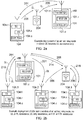
- Figures 2a and 2b provide example scenarios in which a communications device 204 forms an ad-hoc relay node to facilitate communication of radio signals to communications devices (UEs) 104.
- the UEs may be MTC-UEs.
- a base station or eNodeB 101 transmits downlink transmissions 201 via an LTE-type wireless access interface to UEs 104 which as already mentioned may be MTC type UEs.
- the base station or eNodeB 101 includes a transmitter 101. tx, a receiver 101. rx and a controller or scheduler 101. ct.
- the UEs 104 includes a transmitter 104.tx, a receiver 104.rx and a controller 104.ct.
- MTC type UEs may be disposed in a remote location such as a basement of a house or within a car and therefore radio transmission and reception from the UEs may be difficult.
- MTC-UEs themselves are likely to be low power devices and therefore, for example, may be battery powered.
- the UEs 104 may be limited in their transmission power in addition to being disposed in a location, which makes radio communications difficult.
- the eNodeB 101 is not as limited in transmission power and therefore the downlink transmission signals 201 are more likely to be receivable by the UEs 104 in situations in which up-link transmissions from the MTC-UE may not reach the eNodeB 101.
- a communications apparatus may operate as a relay node 204 provides uplink assistance only for the UE 104 and so receives signals 206 from the UE 104 and retransmit the signals from the relay node 204 to the base station 101 represented by an arrow 208.
- FIG. 2b provides an illustration of a mixture of scenarios.
- a first UE 104.1 does not require assistance for either the uplink or the downlink transmissions 210, 211.
- a second UE 104.2 is provided with assistance for uplink transmissions only using a relay node 204 and so corresponds to the example provided in Figure 2a .
- a third UE 104.3 requires assistance for both downlink and uplink transmissions and so for the downlink the communications apparatus 204 receives the downlink transmissions 214 and retransmits the downlink signals received from the eNB 101 to the UE 104.3 via signals 216.
- Figure 2b presents a more realistic scenario in which UEs are deployed within a cell and therefore may either require no assistance for the uplink or the downlink, assistance for the uplink only or assistance for the uplink and the downlink depending on radio communications conditions.
- the 20dB coverage extension target can be achieved using power spectral density (PSD) boosting the narrow band virtual (by offloading the resource blocks used by normal LTE usage) [4]; hence this idea has been vigorously followed for PDSCH as well as PBCH and PDCCH (including VC-PDCCH).
- PSD power spectral density
- a Virtual Carrier corresponds in essence to a narrowband carrier for MTC-type devices within a host carrier for an OFDM-based radio access technology (such as WiMAX or LTE).
- the virtual carrier concept is described in a number of co-pending patent applications (including GB 1101970.0 [7], GB 1101981.7 [8], GB 1101966.8 [9], GB 1101983.3 [10], GB 1101853.8 [11], GB 1101982.5 [12], GB 1101980.9 [13] and GB 1101972.6 [14]).
- FIG. 3 provides a simplified example of the downlink of the wireless access interface when provided by OFDM in accordance with LTE.
- Each subframe 301 is 1ms in duration and may be further divided into two slots of 0.5ms duration.
- the subframes 301 may be grouped together into frames which are formed from ten subframes.
- Each subframe 301 may include user plane and control plane data, where control plane data may for example be conveyed across a physical downlink control channel (PDCCH) 301 and user plane data conveyed across a physical downlink shared channel (PDSCH) 304.
- PDCCH physical downlink control channel
- PDSCH physical downlink shared channel
- a region 306 comprising a central six resource blocks (RBs), which are the equivalent of 1.4MHz) of the available bandwidth, provides a reserved set of resources for a VC-PDSCH 308 and a VC-PDCCH 310.
- MTC devices which are reduced capability devices can communicate via an LTE-like wireless access interface using a transmitter and receiver, which is limited in frequency to that of the central region 306.
- Figure 4 provides a graphical representation of OFDM sub-carriers 401, which represented as power with respect to frequency. As represented by a region 404 and an arrow 406, PSD boosting is applied to VC-PDSCH by unloading some resource blocks from either sides of central 1.4 MHz as illustrated in Figure 4 wherein it is shown that six resource blocks are unloaded to provide 3dB boost to VC-PDSCH.
- the power of MTC PDSCH is boosted according to the value determined from: 10 log 10 M + N M where M and N denote the number of resource blocks allocated to the MTC PDSCH and number of unloaded resource blocks, respectively.
- the PSD boosting is an effective approach for downlink coverage improvement when extra time-frequency (TF) resource blocks are available for power aggregation; an ideal implementation scenario is during the night when the traffic in the network is significantly reduced. Therefore, the downlink PSD boosting transmission could be scheduled in such a specific, quieter time period, which does make sense for MTC services that operate on a delay non- sensitive basis. However, in some cases there may not be enough time and frequency resource blocks available in a cell, and in some specific scenarios for example fire alarm, earthquake warning, etc., communications may be preferably done without significant delay. Downlink relay assisted transmission is an alternative for those scenarios. Then the main question is how and when the connection switches between the two approaches.
- TF time-frequency
- the MME 110 in the core network knows the location of a UE at the accuracy of Tracking Area (TA), and paging starts in the tracking area where the UE last registered to the network. After the eNBs under the tracking area being paged have sent a paging message in all the cells, the UE is expected to start Random Access procedure in order to establish radio link connection.
- TA Tracking Area
- Relay Nodes that can connect to the UE with a different, non-3GPP RAT, can greatly facilitate the reduction in paging messages.
- discovering relay nodes 204 which are available to assist in downlink communications to a UE 104.3 represents a technical problem which is addressed by embodiments of the present technique.
- Example embodiments of the present technique will now be described in which four separate procedures relating to downlink relay assisted transmission are presented, namely, the procedure at the MME, the procedure at the eNB, the procedure at the relay node and the procedure at the MTC-UE, respectively.
- a timer ( T paging ) and an indicator ( N paging ) are defined in the MME (see Figure 5 ). These are defined as:
- the ordinary LTE paging should be performed because radio channel conditions for reception at a UE's current location will not be know by the MME and eNB, and may be sufficiently good to receive a first downlink paging message. This is referred to as the first stage of paging. Should paging at the first stage fail, the second stage (t> T paging ) arises with PSD boosting for paging and/or relay node discovery triggered by the eNB. This approach has an advantage that this would avoid every time activating all the eNBs sending PSD boosted physical channels in all the cells or connecting with multiple relay nodes in the first instance.
- Branch 1 is defined for the scenario where the MTC-UE (and normal UE) is at a good location, so that the channel condition is strong enough to facilitate LTE downlink and uplink communications directly between the eNB and the UE (without any uplink or downlink relay support).
- the downlink and uplink transmission cannot be achieved directly between UE and eNB without relay node support.
- any MTC-UE will sooner or later have something to transmit or it will have to do periodical Tracking Area Updates (TAU).
- the relay nodes that assist UEs in the cell would have a table of UE identifiers listing the UEs which they have already assisted or may have discovered.
- the MME sends a paging request to the eNBs in the tracking area, the paging message sent in a cell is read by all the UEs and also by the relay node. Then the relay node assisted transmission could be triggered by the relay node itself.
- N paging 0
- the normal LTE paging on the tracking areas will fail.
- Embodiments of the present technique can provide an arrangement in which an indication flag N paging in the MME is provided, which guides the eNB on whether to use PSD boosted paging or relay node assisted transmission.
- This indication flag is exchanged over, for example, the S1 interface between the MME and the eNB.
- relay node discovery case 1 relay node discovery case 2
- relay node discovery case 2 relay node discovery case 2
- a list of relay node identifiers that are linked to a specific eNB will be retained by the MME.
- N paging 1
- the MME will request the eNBs to page the relay nodes on the list depending on whether the PSD boosting indicator from the eNB is set or not ( N psd-paging , see the procedure at MME).
- N psd-paging 0
- a common paging identifier is established which, when present, makes all the Relay Nodes read the paging record and the appended MTC-UE identifier.
- Npaging 1
- Embodiments of the present technique can provide an arrangement in which a communications device can discover communications apparatus, which can act as relay nodes.
- the communications apparatus may be predesignated or deployed or fixed relay nodes or may be communications devices themselves which are for example provided with a plurality of radio access technologies and so can form an ad-hoc relay node.
- Ad hoc relay nodes are comprised of communications devices which are provided with more than one radio access technology and are configured to act as relay nodes because they are able to communicate with other communications devices and also a base station (eNodeB) or the mobile radio network.
- eNodeB base station
- the communications apparatus may itself be a mobile communications device, smart phone or wireless router.
- the mobile device to relay node communication may therefore be a device-to-device communication as disclosed in our co-pending European patent applications 14153010.5 , 14153540.1 , 14157187.7 , 14154396.7 , 14161202.8 , 14161201.0 , 14161181.4 .
- a relay node discovery may be performed in accordance with a process disclosed in EP14170122.7 .
- FIG. 5 An example procedure at the MME is shown in Figure 5 for the relay node discovery case 1 and Figure 6 for the relay node discovery case 2.
- S- GW serving gateway
- Figure 5 corresponds to the relay node discovery case 1 while Figure 6 is for the relay node discovery case 2 described above.
- Figure 5 illustrates the operation of an MME in accordance with relay discovery case 1 in which a list of available relay nodes is provided to each of one or more base stations where the UE may be reached.
- Figure 5 is summarised as follows:
- N psd - paging 1 (have PSD boosting paging resources)
- the MTC - UE identifier will be sent to the eNBs to page directly (step S7).
- the MME maintains an RN identifier list that links relay nodes to the eNBs under which they have registered, and these relay nodes will be paged independently.
- a common paging identifier is established which, when present, makes all the Relay Nodes read the paging record and the appended MTC UE identifier.
- the common paging procedure includes the delivery of at least the following information from the MME:
- the common paging identifier should be understood by all of the configured relay nodes that an MTC-UE out of the eNB physical channel coverage is being paged by the MME.
- the explicit or implicit MTC-UE identification extracted from the common paging information could be, for example, the MTC-UE's IMSI (International mobile subscriber identity) or any other type of identification that can be mapped to the intended MTC-UE uniquely during the RN-to-MTC- UE connection.
- the MME will send the common paging identifier along with the MTC-UE identifier to all of the eNBs in the tracking areas.
- Figure 6 is a flow diagram which represents the operation of the MME when relay node discovery case 2 is performed in which relay discovery is determined using a common paging identifier. Steps performed in Figure 6 correspond substantially to those in Figure 5 and so they are the same step references. However, Figure 6 differs from this procedure in Figure 5 by step S14 which replaces steps S4 to S8 in Figure 5 .
- step S14 the MME sends a common paging identifier and MTC UE paging identifier to the eNBs in the tracking area and sets the paging flag to be equal to 1. In this case the eNBs proceed to page the MTC UE using the common paging identifier and the MTC's UE paging identifier via the eNB's in the tracking area.
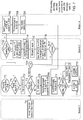
- Figure 7 provides an example flow diagram illustrating the operation of an eNB for the example in which the relay node discovery case 1 is performed.
- the MME communicates a list of relay nodes which are available within each of the coverage areas of base stations of a tracking area where the UE may be located.
- Figure 7 is summarised as follows:
- the procedure is initialized by a paging request from the MME for the MTC-UE arriving at the eNB.
- the eNB has three types of response expected (step T3 in Figure 7 ):
- Branch 1 corresponds to a MTC-UE that is located at good propagation conditions with sufficiently strong channel to support the direct uplink and downlink communications between the eNB and the MTC-UE. Clearly, branch 1 will be successfully executed in the first stage (and therefore, no stage 2 in the following) by the normal LTE paging and PDCCH/PDSCH transmission.
- the MME sends a paging request to the eNBs in the tracking area
- the paging message sent in a cell is read by all the UEs and also by the relay node.
- the relay node will check its lookup list to find out whether the MTC-UE that is being paged is on a list with which it was previously able to communicate (see relay node procedure section for details). Should the relay node successfully match the MTC-UE identifier with one of its lookup identifiers, it may respond to the eNB after verifying that the MTC-UE is reachable by this relay node.
- the relay assisted random access will be operated between the eNB and the UE.
- the relay request on behalf of MTC-UE and the MTC-UE identifier will be exchanged between eNB and relay node.
- two cases of HARQ timeline adjustment are two cases of HARQ timeline adjustment:
- the eNB When the MTC-UE/relay node is connected to the eNB, the eNB will make another judgment in step T8 before sending the data to the target UE/relay node. The judgment result will be sent to relay node/MTC-UE indicated by the new defined indicator N psd :
- the downlink transmission will be done directly to the MTC-UE (step T10).
- the timeline should be adjusted by eNB since now it will be degraded to the uplink-only relay assisted transmission, where the direct downlink has been reached by PSD boosting.
- the delay and HARQ timeline adjustment will be set to reflect the fact that both uplink and downlink are relayed by the relay node.
- the indicator N paging will be set to 1 and triggers PSD boosting for paging or causes the eNB to find a relay node for the MTC-UE actively.
- the procedure will go to the step T11 (branch 3).
- two extra branches (branch 3 and 4) are introduced.
- Branch 3 is the case that the PSD boosting for paging is unavailable, where eNBs will initialize the relay node discovery in the tracking areas.
- two cases are considered in Figures 7 and Figure 8 , respectively.
- all of the eNBs in the tracking areas will first send the availability of the PSD boosting for paging by the indicator N psd-paging back to MME in step T12.
- Multiple relay nodes in the MME paging list will be paged via the eNB and requested to search for the MTC-UE.
- the procedure is as follows: all the relay nodes in the list receiving the page will start random access (step T14) and will set up an RRC connection. After this the eNB will send MTC-UE identifier to all the relay nodes (step T 15) and requests them to find the MTC -UE.
- the eNB will expect one relay node assisted random access on behalf of the UE and receive the HARQ timeline adjustment TTI (step T15).
- T15 receives the HARQ timeline adjustment TTI.
- multiple relay nodes will try to connect to the same MTC-UE and only one (also in the case that the PSD boosting for paging from other cells are failure) should succeed and be selected as the relay.
- a successful relay node discovery for the MTC-UE will lead to step T7, and then later steps will be shared with branch 2.
- Branch 4 differs from branch 3, because the availability of the PSD boosting for paging will lead the procedure to branch 4.
- the availability of sufficient resource blocks drives the direct downlink transmission between the MTC-UE and eNB, only uplink relay node assistance is needed, in step T6, the eNB will follow the same judgment as in branches 2 and 3.
- branch 3 and branch 4 may be implemented simultaneously in different cells under a tracking area (some cells with PSD boosting will perform branch 4, while other perform branch 3).
- the UE will establish radio link connection and set up the radio bearers only via one eNB.
- the UE will know the cell identifier of the serving cell, and would only select a relay node to assist in the uplink if that relay node is connected to the same cell. There is a likelihood that the UE is contacted by a relay node that is camping under a different cell (whilst searching for the paged UE), but is able to reach the UE. The priority would clearly be that the UE would not select that relay node since it is not under the serving cell. Thus there will be no possibility of selecting a different eNB from the downlink one.
- relay node discovery case 1 there is a relay node identifier list maintained at the MME which links eNB identifier and relay node identifier.
- the list could be updated periodically/non-periodically according to the last record of which relay nodes had camped in the eNB in the tracking areas.
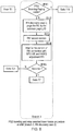
- FIG. 8 An illustration of an operation of the eNB in a situation where the common paging identifier is used to discover relay nodes in accordance with relay node discovery case 2 is represented in Figure 8 which corresponds to branch 3 showing in Figure 7 .
- Figure 8 is summarised as follows:
- the operation of the eNB for relay node discovery case 2 is similar to the case for case 1 shown in Figure 7 , so we have considered only branch 3 is depicted since the other branches are identical to those in Figure 7 .
- This case is different in step T12 where the common paging scheme (relay node discovery case 2) is employed.
- the paging message shall include a common paging identifier which can be read and reacted upon by pre-configured relay nodes, along with an MTC-UE identifier which can map the MTC-UE uniquely.
- the cells without PSD boosting for paging resources will perform the relay node paging using the common paging identifier.
- the random access procedure follows in step T13 and the relay node will try to connect to the MTC-UE according to the common paging information.
- the network there is no need for the network to send a request to the relay node asking for the MTC-UE to search. Again, only one relay node should eventually be successful in connecting to the MTC-UE (in the case that the PSD boosting for paging from other cells are a failure).
- a successful relay node discovery for the MTC-UE will lead to step T7, and then later steps will be shared with branch 2.
- relay node(s) receive the paging message from eNB.
- a relay node will not only check whether its own identifier is included in the paging record but it does the same for all the UEs whose identifier are in the list held at the relay node. In either case, the relay node(s) will start a normal random access in the step 2. Following the random access procedure and RRC connection, the relay node will receive a signal (for example one-bit) from the eNB to indicate whether the forthcoming data in the PSDCH is:
- the indicator N data (also could be explained as a relay request when the eNB target to another MTC-UE) will map its value to the above mentioned two options.
- the MTC-UE identifier will be obtained from eNB and the relay node(s) will try to connect to the MTC-UE (step U6).
- the relay node has to calculate and receive the two HARQ timeline adjustment TTIs from MTC-UE (step U8).
- the relay node assisted downlink and uplink (see Figure 2a ) or uplink only assisted ( Figure 2b ) will be performed in step 11 and step 12 respectively.
- the relay node will check the following three types of paging identifiers in step U1: a common paging identifier, relay node paging identifier or an MTC-UE identifier.
- Branch 2 corresponds to the case that the normal paging applied and the MTC-UE identifier is in the relay node's lookup list.
- the relay node(s) will start to connect to the MTC-UE in Figure 9 ( Figure 9 and Figure 10 ) and only a relay node that successfully connected with the paged UE will pursue the HARQ timeline delay calculation in step U16. Again, the two HARQ timeline delay TTIs will be calculate and received from MTC-UE. The random access is followed in step U17.
- Branch 4 corresponds to the case when the PSD boosting for paging is available; the relay node is selected for uplink random access by MTC-UE after a failure of uplink random access (see [1] for detail), while in this case, UE could be aware that the relay node should be chosen for the downlink assisted transmission after the completion of the paging process since the PSD boosting may be unavailable after successful direct paging. Then the relay node is selected for both uplink and downlink assistance and the HARQ timeline adjustment TTI should be calculated based on Figure 2b . Following the receipt of PSD boosting indicator in step U9, two different relay transmissions will be required. Table 1 Lookup Table for UE identifiers in Paging Records UE ID 1 UE paging ID 1 UE ID 2 UE paging ID 2 UE ID 3 UE paging ID 3 .................
- the common paging identifier is sent to all relay nodes.
- the process performed by the relay node in this is presented in Figure 10 .
- step U3 processing proceeds to step U3 in branch 2.
- a flow diagram representing the operation of the MTC UE is provided in Figure 11 .
- the starting point is when a paging message from the eNB (step W0) or connection request from a relay node (step W10) is received, respectively.
- Different branches 1, 2, 3 or 4 described in the following are selected depending on the where the message/request is coming from.
- the UE will behaviour will be the same.
- the uplink random access procedure will be directly attempted by the UE.
- a successful connection leads to the case of direct uplink and downlink transmission between the UE and eNB, which corresponds to the case that MTC-UE is under favourable propagation conditions.
- a relay node that is used for assisting in the random access procedure may also provide downlink assistance in the following data transmission stage if PSD boosting is consequently unavailable.
- the PSD boosting indicator (for example one-bit) that the UE receives from relay node/eNB identifies the two cases of
- Branch 2 and branch 3 operate in exactly the same way as far as the UE procedure is concerned, regardless of whether the MTC-UE is in the relay node lookup list or not. In either case, the UE will rely on the relay node for both uplink and downlink transmission with eNB since the PSD boosting for paging is unavailable in the respective branches of the flow chart.
Claims (15)
- Station de base (101) dans un réseau de communication mobile pour transmettre des données à des dispositifs de communication (104) ou pour recevoir des données en provenance de dispositifs de communication, la station de base comprenant
un émetteur (101.t) configuré pour transmettre des signaux représentant des données aux dispositifs de communication par le biais d'une interface d'accès sans fil,
un récepteur (101.r) configuré pour recevoir des signaux en provenance des dispositifs de communication par le biais de l'interface d'accès sans fil, et
un dispositif de commande (101.c) conçu
pour commander le récepteur pour recevoir une demande de radiomessagerie en provenance d'une entité de gestion de mobilité (110) du réseau de communication mobile pour une transmission à l'un des dispositifs de communication, et
pour commander l'émetteur pour transmettre, en réponse à la demande de radiomessagerie, un premier message de radiomessagerie au dispositif de communication pour indiquer que le dispositif de communication doit recevoir les données par le biais de l'interface d'accès sans fil,
caractérisée en ce que le dispositif de commande est conçu
pour commander l'émetteur, si une réponse au premier message de radiomessagerie transmis en provenance du dispositif de communication n'est pas reçue par le récepteur pendant un temps prédéterminé et si la station de base peut utiliser un mode d'amplification de puissance, pour transmettre le premier message de radiomessagerie avec une puissance amplifiée pour indiquer que le dispositif de communication doit recevoir les données par le biais de l'interface d'accès sans fil, ou
pour commander l'émetteur, si une réponse au premier message de radiomessagerie transmis en provenance du dispositif de communication n'est pas reçue par le récepteur pendant un temps prédéterminé et si la station de base ne peut pas utiliser un mode de puissance amplifiée pour une transmission, pour transmettre un second message de radiomessagerie à un ou plusieurs appareils de communication qui peuvent fonctionner comme un noeud relais pour le dispositif de communication, le second message de radiomessagerie identifiant le noeud relais et le dispositif de communication pour lequel la station de base doit transmettre les données. - Station de base selon la revendication 1, dans laquelle le dispositif de commande en combinaison avec l'émetteur est conçu
pour recevoir une indication en provenance de l'entité de gestion de mobilité pour transmettre le premier message de radiomessagerie avec une puissance amplifiée et
en réponse à l'indication, pour transmettre le premier message de radiomessagerie avec la puissance amplifiée. - Station de base selon la revendication 1, dans laquelle le dispositif de commande est configuré pour recevoir, de l'entité de gestion de mobilité du réseau de communication, une indication d'un ou de plusieurs appareils de communication qui peuvent faire office de noeuds relais pour le dispositif de communication et le dispositif de commande est configuré, en combinaison avec l'émetteur et le récepteur,
pour transmettre le second message de radiomessagerie à l'appareil de communication pour faire office de noeud relais pour le dispositif de communication pour recevoir les données en provenance de la station de base, qui est identifié par l'indication reçue du gestionnaire de mobilité. - Station de base selon la revendication 2, dans laquelle
si la station de base ne peut pas utiliser un mode de puissance amplifiée pour une transmission, alors le dispositif de commande est configuré pour fournir une indication à l'entité de gestion de mobilité indiquant qu'elle ne peut pas utiliser le mode de puissance amplifiée pour une transmission en réponse à une demande provenant du gestionnaire de mobilité. - Station de base selon la revendication 4, dans laquelle le dispositif de commande est configuré pour recevoir une seconde demande de radiomessagerie en provenance de l'entité de gestion de mobilité si la station de base ne peut pas utiliser le mode de puissance amplifiée et, en réponse, pour transmettre le second message de radiomessagerie à un ou plusieurs appareils de communication qui peuvent fonctionner comme un noeud relais pour le dispositif de communication.
- Procédé de transmission de données à un dispositif de communication (104) à partir d'une station de base (101) dans un réseau de communication mobile, le procédé consistant
à recevoir une demande de radiomessagerie en provenance d'une entité de gestion de mobilité (110) du réseau de communication mobile pour une transmission à l'un des dispositifs de communication, et
à transmettre, en réponse à la demande de radiomessagerie, un premier message de radiomessagerie au dispositif de communication pour indiquer que le dispositif de communication doit recevoir les données par le biais de l'interface d'accès sans fil,
caractérisée en ce que le procédé consiste
si une réponse au premier message de radiomessagerie transmis en provenance du dispositif de communication n'est pas reçue en provenance du dispositif de communication pendant un temps prédéterminé et si la station de base peut utiliser un mode d'amplification de puissance, à transmettre le premier message de radiomessagerie avec une puissance amplifiée pour indiquer que le dispositif de communication doit recevoir les données par le biais de l'interface d'accès sans fil, ou
si une réponse au premier message de radiomessagerie transmis en provenance du dispositif de communication n'est pas reçue par le récepteur pendant un temps prédéterminé et si la station de base ne peut pas utiliser un mode de puissance amplifiée pour une transmission, à transmettre un second message de radiomessagerie à un ou plusieurs appareils de communication qui peuvent fonctionner comme un noeud relais pour le dispositif de communication, le second message de radiomessagerie identifiant le noeud relais et le dispositif de communication pour lequel la station de base doit transmettre les données. - Entité de gestion de mobilité (110) dans un réseau de communication mobile, l'entité de gestion de mobilité comprenant
une interface de communication pour connecter l'entité de gestion de mobilité à une ou plusieurs stations de base (101) dans une zone de suivi du réseau de communication mobile, et
un dispositif de commande configuré, en réponse à la réception d'une indication indiquant que des données doivent être transmises à un dispositif de communication (104) et
pour transmettre, par le biais de l'interface de communication, une demande de radiomessagerie à une ou plusieurs des stations de base dans la zone de suivi pour transmettre un premier message de radiomessagerie au dispositif de communication indiqué dans la demande de radiomessagerie,
caractérisé en ce que le dispositif de commande est configuré
si une réponse au premier message de radiomessagerie transmis en provenance du dispositif de communication n'est pas reçue pendant un temps prédéterminé et si la station de base peut utiliser un mode d'amplification de puissance, pour transmettre, par le biais de l'interface de communication, une seconde demande de radiomessagerie à la ou aux stations de base dans la zone de suivi pour transmettre le premier message de radiomessagerie avec une puissance amplifiée pour indiquer que le dispositif de communication doit recevoir les données par le biais de l'interface d'accès sans fil, ou
si une réponse au premier message de radiomessagerie transmis en provenance du dispositif de communication n'est pas reçue pendant un temps prédéterminé et si la station de base ne peut pas utiliser un mode de puissance amplifiée pour une transmission, pour transmettre, par le biais de l'interface de communication, un second message de radiomessagerie à un ou plusieurs appareils de communication qui peuvent fonctionner comme un noeud relais pour le dispositif de communication, le second message de radiomessagerie identifiant le noeud relais et le dispositif de communication pour lequel la station de base doit transmettre les données. - Entité de gestion de mobilité selon la revendication 7, dans laquelle le dispositif de commande et l'interface de communication en combinaison sont configurés
pour transmettre une demande à la station de base ou à chacune des stations de base dans la zone de suivi pour une indication indiquant si la station de base peut transmettre à l'aide du mode de puissances amplifiée, pour recevoir une indication en provenance de la station de base indiquant si la station de base peut transmettre à l'aide du mode de puissance amplifiée, et si la station de base peut transmettre à l'aide du mode de puissance amplifiée,
pour transmettre une demande à la station de base pour transmettre le premier message de radiomessagerie avec le mode de puissance amplifiée, si une réponse au premier message de radiomessagerie transmis n'est pas reçue pendant le temps prédéterminé ou si la station de base ne peut pas transmettre à l'aide du mode de puissance amplifiée,
pour transmettre une demande à la station de base par le biais de l'interface de communication pour transmettre le second message de radiomessagerie à un ou plusieurs appareils de communication qui peuvent fonctionner comme le noeud relais pour le dispositif de communication. - Entité de gestion de mobilité selon la revendication 7, comprenant un magasin de données, dans laquelle le dispositif de commande est configuré pour stocker, dans le magasin de données, une indication pour la station de base ou pour chacune des stations de base dans la zone de suivi d'un ou de plusieurs appareils de communication qui peuvent faire office de noeuds relais pour des dispositifs de communication, et pour transmettre aux stations de base, qui ne peuvent pas fonctionner avec le mode de puissance amplifiée, une seconde demande de radiomessagerie avec une indication du ou des appareils de communication qui peuvent faire office de noeuds relais pour le dispositif de communication.
- Entité de gestion de mobilité selon la revendication 7, dans laquelle la seconde demande de radiomessagerie comprend une indication d'un identifiant de radiomessagerie commun, qui peut être reconnu par chacun des appareils de communication qui peut faire office de noeud relais pour le dispositif de communication pour recevoir les données en provenance de la station de base, et une indication du dispositif de communication qui doit recevoir les données en provenance de la station de base.
- Entité de gestion de mobilité selon la revendication 7, comprenant un magasin de données, dans laquelle le dispositif de commande est configuré pour détecter si un appareil de communication a fait office de noeud relais pour un ou plusieurs dispositifs de communications qui ont transmis des données à une station de base de desserte ou qui ont reçu des données en provenance de la station de base de desserte par le biais du noeud relais,
pour stocker, dans le magasin de données, une indication du ou des appareils de communication qui ont fait office de noeuds relais, en association avec une indication de leur station de base de desserte, et
pour identifier, à partir de l'indication provenant de la station de base, si elle peut utiliser une amplification de puissance qu'un appareil de communication qui a fait office de noeud relais pour le dispositif de communication aura demandé pour faire office de noeud relais pour le dispositif de communication, et
pour transmettre le second message de radiomessagerie à l'appareil de communication pour faire office de noeud relais pour le dispositif de communication pour recevoir les données en provenance de la station de base de desserte identifiée qui est identifiée par l'indication stockée dans le magasin de données. - Entité de gestion de mobilité selon la revendication 11, dans laquelle le second message de radiomessagerie comprend un identifiant de radiomessagerie commun pour une détection par un ou plusieurs appareils de communication qui peuvent faire office de noeuds relais pour le dispositif de communication pour recevoir les données par le biais de l'interface d'accès sans fil, et une indication du dispositif de communication.
- Procédé de commande d'une transmission de données à un dispositif de communication (104) à partir d'une entité de gestion de mobilité (110) dans un réseau de communication mobile, le procédé consistant
à transmettre, par le biais d'une interface de communication, une demande de radiomessagerie à une ou plusieurs des stations de base dans une zone de suivi pour transmettre un premier message de radiomessagerie au dispositif de communication indiqué dans la demande de radiomessagerie,
caractérisé en ce que le procédé consiste si une réponse au premier message de radiomessagerie transmis en provenance du dispositif de communication n'est pas reçue pendant un temps prédéterminé et si la station de base peut utiliser un mode d'amplification de puissance,
à transmettre, par le biais de l'interface de communication, une seconde demande de radiomessagerie à la ou aux stations de base dans la zone de suivi soit pour transmettre le premier message de radiomessagerie avec une puissance amplifiée pour indiquer que le dispositif de communication doit recevoir les données par le biais de l'interface d'accès sans fil, soit si une réponse au premier message de radiomessagerie transmis en provenance du dispositif de communication n'est pas reçue pendant un temps prédéterminé et si la station de base ne peut pas utiliser un mode de puissance amplifiée pour une transmission, pour transmettre, par le biais de l'interface de communication, un second message de radiomessagerie à un ou plusieurs appareils de communication qui peuvent fonctionner comme un noeud relais pour le dispositif de communication, le second message de radiomessagerie identifiant le noeud relais et le dispositif de communication pour lequel la station de base doit transmettre les données. - Ensemble de circuits électroniques pour une station de base (101) dans un réseau de communication mobile pour transmettre des données à des dispositifs de communication ou pour recevoir des données en provenance de dispositifs de communication (104), l'ensemble de circuits électroniques comprenant
un ensemble de circuits d'émetteur (101.t) configuré pour transmettre des signaux représentant des données aux dispositifs de communication par le biais d'une interface d'accès sans fil,
un ensemble de circuits de récepteur (101.r) configuré pour recevoir des signaux en provenance des dispositifs de communication par le biais de l'interface d'accès sans fil, et
un ensemble de circuits de dispositif de commande (101.c) conçu
pour commander l'ensemble de circuits de récepteur pour recevoir une demande de radiomessagerie en provenance d'une entité de gestion de mobilité (110) du réseau de communication mobile pour une transmission à l'un des dispositifs de communication, et
pour commander l'ensemble de circuits d'émetteur pour transmettre, en réponse à la demande de radiomessagerie, un premier message de radiomessagerie au dispositif de communication pour indiquer que le dispositif de communication doit recevoir les données par le biais de l'interface d'accès sans fil,
caractérisée en ce que l'ensemble de circuits de dispositif de commande est conçu
pour commander l'ensemble de circuits d'émetteur, si une réponse au premier message de radiomessagerie transmis en provenance du dispositif de communication n'est pas reçue par l'ensemble de circuits de récepteur pendant un temps prédéterminé, et si la station de base peut utiliser un mode d'amplification de puissance, pour transmettre le premier message de radiomessagerie avec une puissance amplifiée pour indiquer que le dispositif de communication doit recevoir les données par le biais de l'interface d'accès sans fil, ou
pour commander l'ensemble de circuits d'émetteur, si une réponse au premier message de radiomessagerie transmis en provenance du dispositif de communication n'est pas reçue par l'ensemble de circuits de récepteur pendant un temps prédéterminé et si la station de base ne peut pas utiliser un mode de puissance amplifiée pour une transmission, pour transmettre un second message de radiomessagerie à un ou plusieurs appareils de communication qui peuvent fonctionner comme un noeud relais pour le dispositif de communication, le second message de radiomessagerie identifiant le noeud relais et le dispositif de communication pour lequel la station de base doit transmettre les données. - Ensemble de circuits électroniques pour une entité de gestion de mobilité (110) dans un réseau de communication mobile, l'ensemble de circuits électroniques comprenant
un ensemble de circuits d'interface de communication pour connecter l'entité de gestion de mobilité à une ou plusieurs stations de base (101) dans une zone de suivi du réseau de communication mobile, et
un ensemble de circuits de dispositif de commande configuré, en réponse à la réception d'une indication indiquant que des données doivent être transmises à un dispositif de communication (104) et
pour transmettre, par le biais de l'interface de communication, une demande de radiomessagerie à une ou plusieurs des stations de base dans la zone de suivi pour transmettre un premier message de radiomessagerie au dispositif de communication indiqué dans la demande de radiomessagerie,
caractérisé en ce que l'ensemble de circuits de dispositif de commande est configuré
si une réponse au premier message de radiomessagerie transmis en provenance du dispositif de communication n'est pas reçue pendant un temps prédéterminé et si la station de base peut utiliser un mode d'amplification de puissance, pour transmettre, par le biais de l'interface de communication, une seconde demande de radiomessagerie à la ou aux stations de base dans la zone de suivi soit pour transmettre le premier message de radiomessagerie avec une puissance amplifiée pour indiquer que le dispositif de communication doit recevoir les données par le biais de l'interface d'accès sans fil, soit
si une réponse au premier message de radiomessagerie transmis en provenance du dispositif de communication n'est pas reçue pendant un temps prédéterminé et si la station de base ne peut pas utiliser un mode de puissance amplifiée pour une transmission, pour transmettre, par le biais de l'interface de communication, un second message de radiomessagerie à un ou plusieurs appareils de communication qui peuvent fonctionner comme un noeud relais pour le dispositif de communication, le second message de radiomessagerie identifiant le noeud relais et le dispositif de communication pour lequel la station de base doit transmettre les données.
Applications Claiming Priority (2)
| Application Number | Priority Date | Filing Date | Title |
|---|---|---|---|
| EP14186922 | 2014-09-29 | ||
| PCT/EP2015/068154 WO2016050401A1 (fr) | 2014-09-29 | 2015-08-06 | Équipement d'infrastructure et procédés |
Publications (2)
| Publication Number | Publication Date |
|---|---|
| EP3187011A1 EP3187011A1 (fr) | 2017-07-05 |
| EP3187011B1 true EP3187011B1 (fr) | 2019-10-02 |
Family
ID=51661894
Family Applications (1)
| Application Number | Title | Priority Date | Filing Date |
|---|---|---|---|
| EP15750340.0A Active EP3187011B1 (fr) | 2014-09-29 | 2015-08-06 | Équipement d'infrastructure et procédés |
Country Status (3)
| Country | Link |
|---|---|
| US (1) | US10111200B2 (fr) |
| EP (1) | EP3187011B1 (fr) |
| WO (1) | WO2016050401A1 (fr) |
Families Citing this family (12)
| Publication number | Priority date | Publication date | Assignee | Title |
|---|---|---|---|---|
| US10624078B2 (en) * | 2014-12-21 | 2020-04-14 | Lg Electronics Inc. | Network cooperative communication method for traffic distribution in wireless communication system, and apparatus therefor |
| EP3297390B1 (fr) | 2014-12-23 | 2023-07-19 | Sony Group Corporation | Procédés, unité d'infrastructure, station de base et unité de réseau |
| US11382080B2 (en) | 2015-01-09 | 2022-07-05 | Apple Inc. | System information signaling for link budget limited wireless devices |
| EP3231230B1 (fr) * | 2015-04-20 | 2020-09-16 | HFI Innovation Inc. | Radiomessagerie améliorée pour ue de communication de type machine (mtc) à faible coût (lc) |
| US10091775B2 (en) * | 2015-08-18 | 2018-10-02 | Apple Inc. | Non-PDCCH signaling of SIB resource assignment |
| JP6163181B2 (ja) * | 2015-08-21 | 2017-07-12 | 株式会社Nttドコモ | ユーザ端末、無線基地局及び無線通信方法 |
| WO2017065557A1 (fr) * | 2015-10-14 | 2017-04-20 | Lg Electronics Inc. | Procédé et appareil pour la prise en charge d'équipements d'utilisateur aptes à exécuter une transmission en liaison montante uniquement via un groupage dans un système de communications sans fil |
| US10524108B2 (en) * | 2015-10-19 | 2019-12-31 | Qualomm Incorporated | D2D communication for eMTC design considerations |
| US10517021B2 (en) | 2016-06-30 | 2019-12-24 | Evolve Cellular Inc. | Long term evolution-primary WiFi (LTE-PW) |
| US10542515B2 (en) * | 2016-08-03 | 2020-01-21 | Huawei Technologies Co., Ltd. | Location tracking in wireless networks |
| US10117223B1 (en) * | 2017-01-31 | 2018-10-30 | Sprint Spectrum L.P. | Control of paging based on whether most recent serving base station is a relay base station |
| JP6860686B2 (ja) * | 2017-03-10 | 2021-04-21 | 京セラ株式会社 | バルクRACH MTC(machine type communication)送信 |
Family Cites Families (33)
| Publication number | Priority date | Publication date | Assignee | Title |
|---|---|---|---|---|
| US8238956B1 (en) * | 2003-03-14 | 2012-08-07 | Apple Inc. | Adjusting power of a control channel based on a characteristic of a message in the control channel |
| US7711377B2 (en) * | 2004-06-10 | 2010-05-04 | Qualcomm Incorporated | Efficient paging in a wireless communication system |
| US7760704B2 (en) * | 2004-06-29 | 2010-07-20 | Interdigital Technology Corporation | System and method for call routing and paging across different types of networks |
| US7983696B1 (en) * | 2007-07-02 | 2011-07-19 | Sprint Spectrum L.P. | Dynamic variation of paging power based on paging slot frequency |
| US20100011110A1 (en) * | 2008-07-14 | 2010-01-14 | Nokia Corporation | Mobile terminal to media server connection apparatus, system, and method |
| US8577363B2 (en) * | 2008-07-14 | 2013-11-05 | Nokia Corporation | Setup of device-to-device connection |
| WO2010006649A1 (fr) * | 2008-07-17 | 2010-01-21 | Nokia Siemens Networks Oy | Communications de dispositif à dispositif dans un système cellulaire |
| EP2314118B1 (fr) * | 2008-07-17 | 2015-09-02 | Nokia Solutions and Networks Oy | Sélection de type de connexion dans un système de télécommunications cellulaires |
| US8599768B2 (en) | 2009-08-24 | 2013-12-03 | Intel Corporation | Distributing group size indications to mobile stations |
| US8855566B2 (en) * | 2009-10-19 | 2014-10-07 | Samsung Electronics Co., Ltd. | Apparatus for managing radio resources of base station and method for managing the same |
| US8666403B2 (en) * | 2009-10-23 | 2014-03-04 | Nokia Solutions And Networks Oy | Systems, methods, and apparatuses for facilitating device-to-device connection establishment |
| US8254920B1 (en) * | 2010-08-10 | 2012-08-28 | Sprint Spectrum L.P. | Reducing the usage of non-preferred wireless coverage areas |
| CN102387563B (zh) * | 2010-08-26 | 2015-05-27 | 华为技术有限公司 | 机器类型通讯设备的业务控制方法和相关装置及系统 |
| TW201603506A (zh) | 2011-01-10 | 2016-01-16 | 內數位專利控股公司 | 在肌器對機器或行動輔助佈署中呼叫方法及裝置 |
| GB2487757B (en) | 2011-02-03 | 2015-11-04 | Nvidia Corp | Apparatus and method for reducing interference |
| GB2487906B (en) | 2011-02-04 | 2015-02-25 | Wireless Tech Solutions Llc | Telecommunication method and system |
| GB2487909B8 (en) | 2011-02-04 | 2015-01-21 | Sca Ipla Holdings Inc | Telecommunications method and system |
| GB2487780B (en) | 2011-02-04 | 2015-01-14 | Sca Ipla Holdings Inc | Infrastructure equipment and method |
| GB2487782B (en) | 2011-02-04 | 2015-05-20 | Sca Ipla Holdings Inc | Telecommunications method and system |
| GB2487908B (en) | 2011-02-04 | 2015-06-17 | Sca Ipla Holdings Inc | Telecommunications method and system |
| GB2488513B (en) | 2011-02-04 | 2015-06-24 | Sca Ipla Holdings Inc | Telecommunication method and systen |
| GB2487907B (en) | 2011-02-04 | 2015-08-26 | Sca Ipla Holdings Inc | Telecommunications method and system |
| CN103348609B (zh) * | 2011-02-07 | 2016-10-05 | Lg电子株式会社 | 用于在无线通信系统中接收多播数据的方法及其m2m设备 |
| CN102647666B (zh) * | 2011-02-22 | 2016-06-29 | 华为技术有限公司 | 标识分配方法、组呼方法和通信设备 |
| WO2013009090A2 (fr) * | 2011-07-12 | 2013-01-17 | 엘지전자 주식회사 | Procédé de transmission de données à base de priorité dans un système de communication poste à poste |
| GB2493703C (en) | 2011-08-11 | 2020-03-04 | Sca Ipla Holdings Inc | OFDM subcarrier allocations in wireless telecommunications systems |
| US20130044659A1 (en) * | 2011-08-16 | 2013-02-21 | Renesas Mobile Corporation | Wireless Devices and Base Stations and Methods of Operating |
| GB2497743B (en) | 2011-12-19 | 2017-09-27 | Sca Ipla Holdings Inc | Telecommunications systems and methods |
| US9055389B2 (en) * | 2011-12-30 | 2015-06-09 | Telefonaktiebolaget L M Ericsson (Publ) | Method and network node for handling beacon signal transmission |
| US8897768B2 (en) * | 2012-11-28 | 2014-11-25 | Industrial Technology Research Institute | Method for selecting and establishing a D2D communication path in MTC capillary networks |
| WO2015180890A2 (fr) | 2014-05-27 | 2015-12-03 | Sony Corporation | Dispositif de communication, appareil de communication fonctionnant comme un nœud relais, équipement d'infrastructure et procédés |
| WO2016008657A1 (fr) | 2014-07-15 | 2016-01-21 | Sony Corporation | Dispositif de communication, appareil de communication faisant office de nœud relais, équipement d'infrastructure et procédés associés |
| US9749986B2 (en) * | 2014-08-28 | 2017-08-29 | Apple Inc. | Paging mechanisms for link-budget-limited user devices |
-
2015
- 2015-08-06 US US15/511,540 patent/US10111200B2/en active Active
- 2015-08-06 WO PCT/EP2015/068154 patent/WO2016050401A1/fr active Application Filing
- 2015-08-06 EP EP15750340.0A patent/EP3187011B1/fr active Active
Non-Patent Citations (1)
| Title |
|---|
| None * |
Also Published As
| Publication number | Publication date |
|---|---|
| US10111200B2 (en) | 2018-10-23 |
| EP3187011A1 (fr) | 2017-07-05 |
| US20170289957A1 (en) | 2017-10-05 |
| WO2016050401A1 (fr) | 2016-04-07 |
Similar Documents
| Publication | Publication Date | Title |
|---|---|---|
| EP3187011B1 (fr) | Équipement d'infrastructure et procédés | |
| EP3170341B1 (fr) | Dispositif de communication, appareil de communication faisant office de noeud relais, équipement d'infrastructure et procédés associés | |
| US10512062B2 (en) | Method and apparatus for indicating D2D resource pool in wireless communication system | |
| CN106717052B (zh) | 无线通信系统中取消触发的prose bsr的方法和装置 | |
| CN105981455B (zh) | 在无线通信系统中指示覆盖增强模式的改变的方法和装置 | |
| EP3120607B1 (fr) | Procédé et appareil pour configurer un rapport d'état de tampon pour une transmission de sureté publique dans un système de communication sans fil | |
| US10165590B2 (en) | Method and apparatus for configuring transmission of D2D control information in wireless communication system | |
| CN106165516B (zh) | 在无线通信系统中优先化d2d发送和d2d接收的方法和装置 | |
| US9854566B2 (en) | Method and apparatus for using resources for device-to-device operation in wireless communication system | |
| EP3100478B1 (fr) | Procédé et appareil permettant de transmettre une information pour un fonctionnement d2d dans un système de communication sans fil | |
| CN107592984B (zh) | 在无线通信系统中根据基于竞争的调度请求执行副链路传输的方法和设备 | |
| US20240040611A1 (en) | Channel access priority for sidelink and relay communications in nr-u | |
| US8744483B2 (en) | Method and apparatus for updating location information for a terminal | |
| CN106576336B (zh) | 配置d2d发现特定的逻辑信道组的方法和装置 | |
| CN109923882B (zh) | 用于无线通信系统中的v2x通信的信号传输方法及其设备 | |
| US10111231B2 (en) | Method and apparatus for performing D2D operation in wireless communication system | |
| EP3355644B1 (fr) | Procédés et dispositifs au moyen duquel un service d'ordre prioritaire est transmis | |
| CN107005866B (zh) | 在无线通信系统中通过终端否定传输的方法和设备 | |
| US10321504B2 (en) | Method and device for searching for alternative link in wireless communication system | |
| CN114424627A (zh) | 多通用用户标识模块(musim)用户设备(ue)的处理寻呼和系统信息(si)的方法和装置 | |
| US20140204924A1 (en) | Method and apparatus of performing a discovery procedure | |
| EP3840521B1 (fr) | Procédés et dispositifs pour effectuer une communication dans un système de communication sans fil | |
| US9313718B2 (en) | Method and apparatus for cooperative discovery and in proximity-based service | |
| EP3123782B1 (fr) | Procédé et appareil pour réaliser un contrôle d'accès spécifique de dispositif à dispositif (d2d) dans un système de communication sans fil | |
| US20230061163A1 (en) | Communication system and communication terminal |
Legal Events
| Date | Code | Title | Description |
|---|---|---|---|
| STAA | Information on the status of an ep patent application or granted ep patent |
Free format text: STATUS: THE INTERNATIONAL PUBLICATION HAS BEEN MADE |
|
| PUAI | Public reference made under article 153(3) epc to a published international application that has entered the european phase |
Free format text: ORIGINAL CODE: 0009012 |
|
| STAA | Information on the status of an ep patent application or granted ep patent |
Free format text: STATUS: REQUEST FOR EXAMINATION WAS MADE |
|
| 17P | Request for examination filed |
Effective date: 20170331 |
|
| AK | Designated contracting states |
Kind code of ref document: A1 Designated state(s): AL AT BE BG CH CY CZ DE DK EE ES FI FR GB GR HR HU IE IS IT LI LT LU LV MC MK MT NL NO PL PT RO RS SE SI SK SM TR |
|
| AX | Request for extension of the european patent |
Extension state: BA ME |
|
| DAV | Request for validation of the european patent (deleted) | ||
| DAX | Request for extension of the european patent (deleted) | ||
| STAA | Information on the status of an ep patent application or granted ep patent |
Free format text: STATUS: EXAMINATION IS IN PROGRESS |
|
| 17Q | First examination report despatched |
Effective date: 20181212 |
|
| GRAP | Despatch of communication of intention to grant a patent |
Free format text: ORIGINAL CODE: EPIDOSNIGR1 |
|
| STAA | Information on the status of an ep patent application or granted ep patent |
Free format text: STATUS: GRANT OF PATENT IS INTENDED |
|
| INTG | Intention to grant announced |
Effective date: 20190403 |
|
| GRAS | Grant fee paid |
Free format text: ORIGINAL CODE: EPIDOSNIGR3 |
|
| GRAA | (expected) grant |
Free format text: ORIGINAL CODE: 0009210 |
|
| STAA | Information on the status of an ep patent application or granted ep patent |
Free format text: STATUS: THE PATENT HAS BEEN GRANTED |
|
| AK | Designated contracting states |
Kind code of ref document: B1 Designated state(s): AL AT BE BG CH CY CZ DE DK EE ES FI FR GB GR HR HU IE IS IT LI LT LU LV MC MK MT NL NO PL PT RO RS SE SI SK SM TR |
|
| REG | Reference to a national code |
Ref country code: GB Ref legal event code: FG4D |
|
| REG | Reference to a national code |
Ref country code: CH Ref legal event code: EP Ref country code: AT Ref legal event code: REF Ref document number: 1187645 Country of ref document: AT Kind code of ref document: T Effective date: 20191015 |
|
| REG | Reference to a national code |
Ref country code: DE Ref legal event code: R096 Ref document number: 602015039078 Country of ref document: DE |
|
| REG | Reference to a national code |
Ref country code: IE Ref legal event code: FG4D |
|
| REG | Reference to a national code |
Ref country code: NL Ref legal event code: FP |
|
| REG | Reference to a national code |
Ref country code: LT Ref legal event code: MG4D |
|
| REG | Reference to a national code |
Ref country code: AT Ref legal event code: MK05 Ref document number: 1187645 Country of ref document: AT Kind code of ref document: T Effective date: 20191002 |
|
| PG25 | Lapsed in a contracting state [announced via postgrant information from national office to epo] |
Ref country code: FI Free format text: LAPSE BECAUSE OF FAILURE TO SUBMIT A TRANSLATION OF THE DESCRIPTION OR TO PAY THE FEE WITHIN THE PRESCRIBED TIME-LIMIT Effective date: 20191002 Ref country code: BG Free format text: LAPSE BECAUSE OF FAILURE TO SUBMIT A TRANSLATION OF THE DESCRIPTION OR TO PAY THE FEE WITHIN THE PRESCRIBED TIME-LIMIT Effective date: 20200102 Ref country code: GR Free format text: LAPSE BECAUSE OF FAILURE TO SUBMIT A TRANSLATION OF THE DESCRIPTION OR TO PAY THE FEE WITHIN THE PRESCRIBED TIME-LIMIT Effective date: 20200103 Ref country code: PT Free format text: LAPSE BECAUSE OF FAILURE TO SUBMIT A TRANSLATION OF THE DESCRIPTION OR TO PAY THE FEE WITHIN THE PRESCRIBED TIME-LIMIT Effective date: 20200203 Ref country code: LT Free format text: LAPSE BECAUSE OF FAILURE TO SUBMIT A TRANSLATION OF THE DESCRIPTION OR TO PAY THE FEE WITHIN THE PRESCRIBED TIME-LIMIT Effective date: 20191002 Ref country code: PL Free format text: LAPSE BECAUSE OF FAILURE TO SUBMIT A TRANSLATION OF THE DESCRIPTION OR TO PAY THE FEE WITHIN THE PRESCRIBED TIME-LIMIT Effective date: 20191002 Ref country code: LV Free format text: LAPSE BECAUSE OF FAILURE TO SUBMIT A TRANSLATION OF THE DESCRIPTION OR TO PAY THE FEE WITHIN THE PRESCRIBED TIME-LIMIT Effective date: 20191002 Ref country code: NO Free format text: LAPSE BECAUSE OF FAILURE TO SUBMIT A TRANSLATION OF THE DESCRIPTION OR TO PAY THE FEE WITHIN THE PRESCRIBED TIME-LIMIT Effective date: 20200102 Ref country code: SE Free format text: LAPSE BECAUSE OF FAILURE TO SUBMIT A TRANSLATION OF THE DESCRIPTION OR TO PAY THE FEE WITHIN THE PRESCRIBED TIME-LIMIT Effective date: 20191002 Ref country code: ES Free format text: LAPSE BECAUSE OF FAILURE TO SUBMIT A TRANSLATION OF THE DESCRIPTION OR TO PAY THE FEE WITHIN THE PRESCRIBED TIME-LIMIT Effective date: 20191002 Ref country code: AT Free format text: LAPSE BECAUSE OF FAILURE TO SUBMIT A TRANSLATION OF THE DESCRIPTION OR TO PAY THE FEE WITHIN THE PRESCRIBED TIME-LIMIT Effective date: 20191002 |
|
| PG25 | Lapsed in a contracting state [announced via postgrant information from national office to epo] |
Ref country code: IS Free format text: LAPSE BECAUSE OF FAILURE TO SUBMIT A TRANSLATION OF THE DESCRIPTION OR TO PAY THE FEE WITHIN THE PRESCRIBED TIME-LIMIT Effective date: 20200224 Ref country code: CZ Free format text: LAPSE BECAUSE OF FAILURE TO SUBMIT A TRANSLATION OF THE DESCRIPTION OR TO PAY THE FEE WITHIN THE PRESCRIBED TIME-LIMIT Effective date: 20191002 Ref country code: RS Free format text: LAPSE BECAUSE OF FAILURE TO SUBMIT A TRANSLATION OF THE DESCRIPTION OR TO PAY THE FEE WITHIN THE PRESCRIBED TIME-LIMIT Effective date: 20191002 Ref country code: HR Free format text: LAPSE BECAUSE OF FAILURE TO SUBMIT A TRANSLATION OF THE DESCRIPTION OR TO PAY THE FEE WITHIN THE PRESCRIBED TIME-LIMIT Effective date: 20191002 |
|
| PG25 | Lapsed in a contracting state [announced via postgrant information from national office to epo] |
Ref country code: AL Free format text: LAPSE BECAUSE OF FAILURE TO SUBMIT A TRANSLATION OF THE DESCRIPTION OR TO PAY THE FEE WITHIN THE PRESCRIBED TIME-LIMIT Effective date: 20191002 |
|
| REG | Reference to a national code |
Ref country code: DE Ref legal event code: R097 Ref document number: 602015039078 Country of ref document: DE |
|
| PG2D | Information on lapse in contracting state deleted |
Ref country code: IS |
|
| PG25 | Lapsed in a contracting state [announced via postgrant information from national office to epo] |
Ref country code: EE Free format text: LAPSE BECAUSE OF FAILURE TO SUBMIT A TRANSLATION OF THE DESCRIPTION OR TO PAY THE FEE WITHIN THE PRESCRIBED TIME-LIMIT Effective date: 20191002 Ref country code: DK Free format text: LAPSE BECAUSE OF FAILURE TO SUBMIT A TRANSLATION OF THE DESCRIPTION OR TO PAY THE FEE WITHIN THE PRESCRIBED TIME-LIMIT Effective date: 20191002 Ref country code: RO Free format text: LAPSE BECAUSE OF FAILURE TO SUBMIT A TRANSLATION OF THE DESCRIPTION OR TO PAY THE FEE WITHIN THE PRESCRIBED TIME-LIMIT Effective date: 20191002 Ref country code: IS Free format text: LAPSE BECAUSE OF FAILURE TO SUBMIT A TRANSLATION OF THE DESCRIPTION OR TO PAY THE FEE WITHIN THE PRESCRIBED TIME-LIMIT Effective date: 20200202 |
|
| PLBE | No opposition filed within time limit |
Free format text: ORIGINAL CODE: 0009261 |
|
| STAA | Information on the status of an ep patent application or granted ep patent |
Free format text: STATUS: NO OPPOSITION FILED WITHIN TIME LIMIT |
|
| PG25 | Lapsed in a contracting state [announced via postgrant information from national office to epo] |
Ref country code: IT Free format text: LAPSE BECAUSE OF FAILURE TO SUBMIT A TRANSLATION OF THE DESCRIPTION OR TO PAY THE FEE WITHIN THE PRESCRIBED TIME-LIMIT Effective date: 20191002 Ref country code: SM Free format text: LAPSE BECAUSE OF FAILURE TO SUBMIT A TRANSLATION OF THE DESCRIPTION OR TO PAY THE FEE WITHIN THE PRESCRIBED TIME-LIMIT Effective date: 20191002 Ref country code: SK Free format text: LAPSE BECAUSE OF FAILURE TO SUBMIT A TRANSLATION OF THE DESCRIPTION OR TO PAY THE FEE WITHIN THE PRESCRIBED TIME-LIMIT Effective date: 20191002 |
|
| 26N | No opposition filed |
Effective date: 20200703 |
|
| PG25 | Lapsed in a contracting state [announced via postgrant information from national office to epo] |
Ref country code: SI Free format text: LAPSE BECAUSE OF FAILURE TO SUBMIT A TRANSLATION OF THE DESCRIPTION OR TO PAY THE FEE WITHIN THE PRESCRIBED TIME-LIMIT Effective date: 20191002 |
|
| PG25 | Lapsed in a contracting state [announced via postgrant information from national office to epo] |
Ref country code: MC Free format text: LAPSE BECAUSE OF FAILURE TO SUBMIT A TRANSLATION OF THE DESCRIPTION OR TO PAY THE FEE WITHIN THE PRESCRIBED TIME-LIMIT Effective date: 20191002 |
|
| REG | Reference to a national code |
Ref country code: CH Ref legal event code: PL |
|
| REG | Reference to a national code |
Ref country code: NL Ref legal event code: MM Effective date: 20200901 |
|
| PG25 | Lapsed in a contracting state [announced via postgrant information from national office to epo] |
Ref country code: CH Free format text: LAPSE BECAUSE OF NON-PAYMENT OF DUE FEES Effective date: 20200831 Ref country code: LI Free format text: LAPSE BECAUSE OF NON-PAYMENT OF DUE FEES Effective date: 20200831 Ref country code: LU Free format text: LAPSE BECAUSE OF NON-PAYMENT OF DUE FEES Effective date: 20200806 |
|
| REG | Reference to a national code |
Ref country code: BE Ref legal event code: MM Effective date: 20200831 |
|
| PG25 | Lapsed in a contracting state [announced via postgrant information from national office to epo] |
Ref country code: FR Free format text: LAPSE BECAUSE OF NON-PAYMENT OF DUE FEES Effective date: 20200831 |
|
| PG25 | Lapsed in a contracting state [announced via postgrant information from national office to epo] |
Ref country code: IE Free format text: LAPSE BECAUSE OF NON-PAYMENT OF DUE FEES Effective date: 20200806 Ref country code: BE Free format text: LAPSE BECAUSE OF NON-PAYMENT OF DUE FEES Effective date: 20200831 |
|
| PG25 | Lapsed in a contracting state [announced via postgrant information from national office to epo] |
Ref country code: NL Free format text: LAPSE BECAUSE OF NON-PAYMENT OF DUE FEES Effective date: 20200901 |
|
| PG25 | Lapsed in a contracting state [announced via postgrant information from national office to epo] |
Ref country code: TR Free format text: LAPSE BECAUSE OF FAILURE TO SUBMIT A TRANSLATION OF THE DESCRIPTION OR TO PAY THE FEE WITHIN THE PRESCRIBED TIME-LIMIT Effective date: 20191002 Ref country code: MT Free format text: LAPSE BECAUSE OF FAILURE TO SUBMIT A TRANSLATION OF THE DESCRIPTION OR TO PAY THE FEE WITHIN THE PRESCRIBED TIME-LIMIT Effective date: 20191002 Ref country code: CY Free format text: LAPSE BECAUSE OF FAILURE TO SUBMIT A TRANSLATION OF THE DESCRIPTION OR TO PAY THE FEE WITHIN THE PRESCRIBED TIME-LIMIT Effective date: 20191002 |
|
| PG25 | Lapsed in a contracting state [announced via postgrant information from national office to epo] |
Ref country code: MK Free format text: LAPSE BECAUSE OF FAILURE TO SUBMIT A TRANSLATION OF THE DESCRIPTION OR TO PAY THE FEE WITHIN THE PRESCRIBED TIME-LIMIT Effective date: 20191002 |
|
| P01 | Opt-out of the competence of the unified patent court (upc) registered |
Effective date: 20230527 |
|
| PGFP | Annual fee paid to national office [announced via postgrant information from national office to epo] |
Ref country code: GB Payment date: 20230720 Year of fee payment: 9 |
|
| PGFP | Annual fee paid to national office [announced via postgrant information from national office to epo] |
Ref country code: DE Payment date: 20230720 Year of fee payment: 9 |