EP3186018B1 - Organic waste digester system - Google Patents
Organic waste digester system Download PDFInfo
- Publication number
- EP3186018B1 EP3186018B1 EP15830090.5A EP15830090A EP3186018B1 EP 3186018 B1 EP3186018 B1 EP 3186018B1 EP 15830090 A EP15830090 A EP 15830090A EP 3186018 B1 EP3186018 B1 EP 3186018B1
- Authority
- EP
- European Patent Office
- Prior art keywords
- microwave
- organic waste
- disposed
- drying unit
- hopper
- Prior art date
- Legal status (The legal status is an assumption and is not a legal conclusion. Google has not performed a legal analysis and makes no representation as to the accuracy of the status listed.)
- Not-in-force
Links
Images








Classifications
-
- C—CHEMISTRY; METALLURGY
- C12—BIOCHEMISTRY; BEER; SPIRITS; WINE; VINEGAR; MICROBIOLOGY; ENZYMOLOGY; MUTATION OR GENETIC ENGINEERING
- C12M—APPARATUS FOR ENZYMOLOGY OR MICROBIOLOGY; APPARATUS FOR CULTURING MICROORGANISMS FOR PRODUCING BIOMASS, FOR GROWING CELLS OR FOR OBTAINING FERMENTATION OR METABOLIC PRODUCTS, i.e. BIOREACTORS OR FERMENTERS
- C12M45/00—Means for pre-treatment of biological substances
- C12M45/20—Heating; Cooling
-
- C—CHEMISTRY; METALLURGY
- C05—FERTILISERS; MANUFACTURE THEREOF
- C05F—ORGANIC FERTILISERS NOT COVERED BY SUBCLASSES C05B, C05C, e.g. FERTILISERS FROM WASTE OR REFUSE
- C05F9/00—Fertilisers from household or town refuse
- C05F9/02—Apparatus for the manufacture
-
- A—HUMAN NECESSITIES
- A23—FOODS OR FOODSTUFFS; TREATMENT THEREOF, NOT COVERED BY OTHER CLASSES
- A23K—FODDER
- A23K20/00—Accessory food factors for animal feeding-stuffs
- A23K20/10—Organic substances
-
- B—PERFORMING OPERATIONS; TRANSPORTING
- B02—CRUSHING, PULVERISING, OR DISINTEGRATING; PREPARATORY TREATMENT OF GRAIN FOR MILLING
- B02C—CRUSHING, PULVERISING, OR DISINTEGRATING IN GENERAL; MILLING GRAIN
- B02C18/00—Disintegrating by knives or other cutting or tearing members which chop material into fragments
- B02C18/0084—Disintegrating by knives or other cutting or tearing members which chop material into fragments specially adapted for disintegrating garbage, waste or sewage
-
- B—PERFORMING OPERATIONS; TRANSPORTING
- B02—CRUSHING, PULVERISING, OR DISINTEGRATING; PREPARATORY TREATMENT OF GRAIN FOR MILLING
- B02C—CRUSHING, PULVERISING, OR DISINTEGRATING IN GENERAL; MILLING GRAIN
- B02C23/00—Auxiliary methods or auxiliary devices or accessories specially adapted for crushing or disintegrating not provided for in preceding groups or not specially adapted to apparatus covered by a single preceding group
- B02C23/02—Feeding devices
-
- B—PERFORMING OPERATIONS; TRANSPORTING
- B09—DISPOSAL OF SOLID WASTE; RECLAMATION OF CONTAMINATED SOIL
- B09B—DISPOSAL OF SOLID WASTE NOT OTHERWISE PROVIDED FOR
- B09B3/00—Destroying solid waste or transforming solid waste into something useful or harmless
- B09B3/50—Destroying solid waste or transforming solid waste into something useful or harmless involving radiation, e.g. electro-magnetic waves
-
- C—CHEMISTRY; METALLURGY
- C05—FERTILISERS; MANUFACTURE THEREOF
- C05F—ORGANIC FERTILISERS NOT COVERED BY SUBCLASSES C05B, C05C, e.g. FERTILISERS FROM WASTE OR REFUSE
- C05F11/00—Other organic fertilisers
- C05F11/08—Organic fertilisers containing added bacterial cultures, mycelia or the like
-
- C—CHEMISTRY; METALLURGY
- C05—FERTILISERS; MANUFACTURE THEREOF
- C05F—ORGANIC FERTILISERS NOT COVERED BY SUBCLASSES C05B, C05C, e.g. FERTILISERS FROM WASTE OR REFUSE
- C05F17/00—Preparation of fertilisers characterised by biological or biochemical treatment steps, e.g. composting or fermentation
- C05F17/60—Heating or cooling during the treatment
-
- C—CHEMISTRY; METALLURGY
- C05—FERTILISERS; MANUFACTURE THEREOF
- C05F—ORGANIC FERTILISERS NOT COVERED BY SUBCLASSES C05B, C05C, e.g. FERTILISERS FROM WASTE OR REFUSE
- C05F17/00—Preparation of fertilisers characterised by biological or biochemical treatment steps, e.g. composting or fermentation
- C05F17/90—Apparatus therefor
-
- C—CHEMISTRY; METALLURGY
- C10—PETROLEUM, GAS OR COKE INDUSTRIES; TECHNICAL GASES CONTAINING CARBON MONOXIDE; FUELS; LUBRICANTS; PEAT
- C10L—FUELS NOT OTHERWISE PROVIDED FOR; NATURAL GAS; SYNTHETIC NATURAL GAS OBTAINED BY PROCESSES NOT COVERED BY SUBCLASSES C10G OR C10K; LIQUIFIED PETROLEUM GAS; USE OF ADDITIVES TO FUELS OR FIRES; FIRE-LIGHTERS
- C10L5/00—Solid fuels
- C10L5/40—Solid fuels essentially based on materials of non-mineral origin
- C10L5/44—Solid fuels essentially based on materials of non-mineral origin on vegetable substances
- C10L5/445—Agricultural waste, e.g. corn crops, grass clippings, nut shells or oil pressing residues
-
- C—CHEMISTRY; METALLURGY
- C12—BIOCHEMISTRY; BEER; SPIRITS; WINE; VINEGAR; MICROBIOLOGY; ENZYMOLOGY; MUTATION OR GENETIC ENGINEERING
- C12M—APPARATUS FOR ENZYMOLOGY OR MICROBIOLOGY; APPARATUS FOR CULTURING MICROORGANISMS FOR PRODUCING BIOMASS, FOR GROWING CELLS OR FOR OBTAINING FERMENTATION OR METABOLIC PRODUCTS, i.e. BIOREACTORS OR FERMENTERS
- C12M45/00—Means for pre-treatment of biological substances
- C12M45/02—Means for pre-treatment of biological substances by mechanical forces; Stirring; Trituration; Comminuting
-
- C—CHEMISTRY; METALLURGY
- C12—BIOCHEMISTRY; BEER; SPIRITS; WINE; VINEGAR; MICROBIOLOGY; ENZYMOLOGY; MUTATION OR GENETIC ENGINEERING
- C12M—APPARATUS FOR ENZYMOLOGY OR MICROBIOLOGY; APPARATUS FOR CULTURING MICROORGANISMS FOR PRODUCING BIOMASS, FOR GROWING CELLS OR FOR OBTAINING FERMENTATION OR METABOLIC PRODUCTS, i.e. BIOREACTORS OR FERMENTERS
- C12M45/00—Means for pre-treatment of biological substances
- C12M45/03—Means for pre-treatment of biological substances by control of the humidity or content of liquids; Drying
-
- C—CHEMISTRY; METALLURGY
- C10—PETROLEUM, GAS OR COKE INDUSTRIES; TECHNICAL GASES CONTAINING CARBON MONOXIDE; FUELS; LUBRICANTS; PEAT
- C10L—FUELS NOT OTHERWISE PROVIDED FOR; NATURAL GAS; SYNTHETIC NATURAL GAS OBTAINED BY PROCESSES NOT COVERED BY SUBCLASSES C10G OR C10K; LIQUIFIED PETROLEUM GAS; USE OF ADDITIVES TO FUELS OR FIRES; FIRE-LIGHTERS
- C10L2290/00—Fuel preparation or upgrading, processes or apparatus therefore, comprising specific process steps or apparatus units
- C10L2290/08—Drying or removing water
-
- C—CHEMISTRY; METALLURGY
- C10—PETROLEUM, GAS OR COKE INDUSTRIES; TECHNICAL GASES CONTAINING CARBON MONOXIDE; FUELS; LUBRICANTS; PEAT
- C10L—FUELS NOT OTHERWISE PROVIDED FOR; NATURAL GAS; SYNTHETIC NATURAL GAS OBTAINED BY PROCESSES NOT COVERED BY SUBCLASSES C10G OR C10K; LIQUIFIED PETROLEUM GAS; USE OF ADDITIVES TO FUELS OR FIRES; FIRE-LIGHTERS
- C10L2290/00—Fuel preparation or upgrading, processes or apparatus therefore, comprising specific process steps or apparatus units
- C10L2290/24—Mixing, stirring of fuel components
-
- C—CHEMISTRY; METALLURGY
- C10—PETROLEUM, GAS OR COKE INDUSTRIES; TECHNICAL GASES CONTAINING CARBON MONOXIDE; FUELS; LUBRICANTS; PEAT
- C10L—FUELS NOT OTHERWISE PROVIDED FOR; NATURAL GAS; SYNTHETIC NATURAL GAS OBTAINED BY PROCESSES NOT COVERED BY SUBCLASSES C10G OR C10K; LIQUIFIED PETROLEUM GAS; USE OF ADDITIVES TO FUELS OR FIRES; FIRE-LIGHTERS
- C10L2290/00—Fuel preparation or upgrading, processes or apparatus therefore, comprising specific process steps or apparatus units
- C10L2290/26—Composting, fermenting or anaerobic digestion fuel components or materials from which fuels are prepared
-
- C—CHEMISTRY; METALLURGY
- C10—PETROLEUM, GAS OR COKE INDUSTRIES; TECHNICAL GASES CONTAINING CARBON MONOXIDE; FUELS; LUBRICANTS; PEAT
- C10L—FUELS NOT OTHERWISE PROVIDED FOR; NATURAL GAS; SYNTHETIC NATURAL GAS OBTAINED BY PROCESSES NOT COVERED BY SUBCLASSES C10G OR C10K; LIQUIFIED PETROLEUM GAS; USE OF ADDITIVES TO FUELS OR FIRES; FIRE-LIGHTERS
- C10L2290/00—Fuel preparation or upgrading, processes or apparatus therefore, comprising specific process steps or apparatus units
- C10L2290/36—Applying radiation such as microwave, IR, UV
-
- Y—GENERAL TAGGING OF NEW TECHNOLOGICAL DEVELOPMENTS; GENERAL TAGGING OF CROSS-SECTIONAL TECHNOLOGIES SPANNING OVER SEVERAL SECTIONS OF THE IPC; TECHNICAL SUBJECTS COVERED BY FORMER USPC CROSS-REFERENCE ART COLLECTIONS [XRACs] AND DIGESTS
- Y02—TECHNOLOGIES OR APPLICATIONS FOR MITIGATION OR ADAPTATION AGAINST CLIMATE CHANGE
- Y02A—TECHNOLOGIES FOR ADAPTATION TO CLIMATE CHANGE
- Y02A40/00—Adaptation technologies in agriculture, forestry, livestock or agroalimentary production
- Y02A40/10—Adaptation technologies in agriculture, forestry, livestock or agroalimentary production in agriculture
- Y02A40/20—Fertilizers of biological origin, e.g. guano or fertilizers made from animal corpses
-
- Y—GENERAL TAGGING OF NEW TECHNOLOGICAL DEVELOPMENTS; GENERAL TAGGING OF CROSS-SECTIONAL TECHNOLOGIES SPANNING OVER SEVERAL SECTIONS OF THE IPC; TECHNICAL SUBJECTS COVERED BY FORMER USPC CROSS-REFERENCE ART COLLECTIONS [XRACs] AND DIGESTS
- Y02—TECHNOLOGIES OR APPLICATIONS FOR MITIGATION OR ADAPTATION AGAINST CLIMATE CHANGE
- Y02E—REDUCTION OF GREENHOUSE GAS [GHG] EMISSIONS, RELATED TO ENERGY GENERATION, TRANSMISSION OR DISTRIBUTION
- Y02E50/00—Technologies for the production of fuel of non-fossil origin
- Y02E50/10—Biofuels, e.g. bio-diesel
-
- Y—GENERAL TAGGING OF NEW TECHNOLOGICAL DEVELOPMENTS; GENERAL TAGGING OF CROSS-SECTIONAL TECHNOLOGIES SPANNING OVER SEVERAL SECTIONS OF THE IPC; TECHNICAL SUBJECTS COVERED BY FORMER USPC CROSS-REFERENCE ART COLLECTIONS [XRACs] AND DIGESTS
- Y02—TECHNOLOGIES OR APPLICATIONS FOR MITIGATION OR ADAPTATION AGAINST CLIMATE CHANGE
- Y02E—REDUCTION OF GREENHOUSE GAS [GHG] EMISSIONS, RELATED TO ENERGY GENERATION, TRANSMISSION OR DISTRIBUTION
- Y02E50/00—Technologies for the production of fuel of non-fossil origin
- Y02E50/30—Fuel from waste, e.g. synthetic alcohol or diesel
-
- Y—GENERAL TAGGING OF NEW TECHNOLOGICAL DEVELOPMENTS; GENERAL TAGGING OF CROSS-SECTIONAL TECHNOLOGIES SPANNING OVER SEVERAL SECTIONS OF THE IPC; TECHNICAL SUBJECTS COVERED BY FORMER USPC CROSS-REFERENCE ART COLLECTIONS [XRACs] AND DIGESTS
- Y02—TECHNOLOGIES OR APPLICATIONS FOR MITIGATION OR ADAPTATION AGAINST CLIMATE CHANGE
- Y02P—CLIMATE CHANGE MITIGATION TECHNOLOGIES IN THE PRODUCTION OR PROCESSING OF GOODS
- Y02P20/00—Technologies relating to chemical industry
- Y02P20/141—Feedstock
- Y02P20/145—Feedstock the feedstock being materials of biological origin
-
- Y—GENERAL TAGGING OF NEW TECHNOLOGICAL DEVELOPMENTS; GENERAL TAGGING OF CROSS-SECTIONAL TECHNOLOGIES SPANNING OVER SEVERAL SECTIONS OF THE IPC; TECHNICAL SUBJECTS COVERED BY FORMER USPC CROSS-REFERENCE ART COLLECTIONS [XRACs] AND DIGESTS
- Y02—TECHNOLOGIES OR APPLICATIONS FOR MITIGATION OR ADAPTATION AGAINST CLIMATE CHANGE
- Y02W—CLIMATE CHANGE MITIGATION TECHNOLOGIES RELATED TO WASTEWATER TREATMENT OR WASTE MANAGEMENT
- Y02W30/00—Technologies for solid waste management
- Y02W30/40—Bio-organic fraction processing; Production of fertilisers from the organic fraction of waste or refuse
Definitions
- Organic waste is a large component of all waste generated by households, businesses and institutions.
- An organic waste digester system reduces the volume of organic waste by 80-90%.
- the discharge product can be composted more rapidly than organic waste that has not been first digested. It also has application as an animal feed amendment as well as a fuel source. Also, if not subsequently utilized, the discharge product takes up much less volume in a landfill.
- the organic waste digester system includes a housing and a control system.
- a hopper unit is located within the housing, having an opening to receive organic waste.
- An agitation mechanism mixes the organic waste, and a heater heats the organic waste in the hopper unit.
- a microbe mixture is added to aid in the breakdown of the organic waste.
- the liquefied organic waste is discharged through an outlet to a drying unit downstream of the hopper unit.
- the drying unit comprises a microwave drying unit including a microwave chamber and one or more magnetrons disposed to introduce microwave energy via one or more waveguides into the microwave chamber.
- An organic waste digester system can recycle organic waste including raw and cooked fish, meat and poultry, small bones, eggs and egg shells, fruits, vegetables, dairy products, and grain products.
- organic waste including raw and cooked fish, meat and poultry, small bones, eggs and egg shells, fruits, vegetables, dairy products, and grain products.
- the organic waste is degraded and liquefied by heating and mixing. This process is accelerated by the addition of microbes.
- the liquefied waste is dried and dehydrated.
- the discharge product is 80-90% dry and reduced in mass by 80-90%. It is stable and can be stored for several months.
- This discharge product is a compostable material and can be sent to a compositing facility or to a landfill.
- the discharge product also has uses as an animal feed amendment or a fuel source.
- the system 10 includes a housing 20 for housing the system formed of various structural framing elements 22 connected to form a frame and covered by side panels 24, lower panel 25, and upper panel 26.
- An opening 28, covered with a lid 32, in the upper panel of the housing provides access to the hopper unit 40.
- Organic waste can be deposited directly into the hopper unit 40 through this opening.
- the system also includes a chopper or grinder unit 110, described further below.
- the hopper unit 40 includes a main hopper 42 comprising a hopper bin 44, for example of panels of stainless steel welded or otherwise joined and formed into an appropriate bin shape to receive the waste.
- the hopper bin includes two side panels 46, two end panels 48, and a bottom panel 52.
- the bin is supported within the housing 20 by suitable framing elements 54.
- the main hopper also includes an entrance trough 56 having an open bottom 58 through which the waste is delivered. Waste is deposited into the chopper unit 110, from where it passes through opening 27 into the trough 56 and then into the hopper bin 44.
- a microbe mixture that accelerates the breaking down of the food waste is added directly into the main hopper 42, for example, through the opening 28, covered by a lid 32.
- the microbe mixture typically can be restocked periodically, such as weekly, monthly, quarterly, or annually.
- Mixing of the organic waste with the microbe mixture begins breaking down and liquefying the organic waste.
- Suitable microbe mixtures for the liquefaction of organic waste are known and can be used.
- the microbes can self-regulate their population based on the food supply. In times of high usage and volume, the microbes reproduce and in times of low volume they slow reproduction and go into a dormant state. Users can also view the level of material in the hopper unit through the opening 28 to ensure that the hopper unit is not overfilled.
- the bottom panel 52 is formed with a large opening 68 crossed by with slats 72 spaced apart to form the apertures 64.
- the apertures can be formed in another other manner, such as by providing slits, slots, or holes in the bottom panel or by placing a screen over a large opening in the bottom panel.
- the hopper unit also includes an agitation mechanism 70 to mix the organic waste to help it break down in the presence of the microbe mixture. See also Figs. 11-15 .
- the agitation mechanism includes a number of auger paddles 72 disposed along an agitator drive shaft 74 in a staggered orientation within the bin 44 of the main hopper 42.
- each auger paddle 72 includes a shaft 76 extending orthogonally from the drive shaft to assist the mixing of the food waste.
- a paddle 78 is disposed at the end of the shaft.
- the paddle can have any suitable configuration, such as flat or chevron-shaped.
- Blades 82 can be disposed along sides of the shaft to help the paddles cut through the organic waste. Eight to ten auger paddles are generally sufficient, although any suitable number can be used, depending on the size of the hopper unit.
- the main hopper 42 can be heated in any suitable manner.
- a mat heater can be attached directly to the outer surfaces of the panels of the hopper.
- the hopper is heated to a temperature range of 27 to 49°C (80 to 120°F).
- the hopper bin can include a layer of an insulating material to retain heat.
- the chopper unit 110 initially chops all the organic material, including meat and small bones, that is deposited into the hopper unit, thereby increasing the surface area of the organic waste, which speeds up decomposition.
- the chopper unit includes a hopper 112 mounted above the opening 27 in the surface 26 of the housing 20, and a chopping blade mechanism 114 that fits within the trough 56.
- An opening 116 covered with a lid 118 provides access to the hopper 112.
- the chopping blade mechanism 114 includes a pair of meshing rotary cutters.
- the chopping blade mechanism can include a rotary chopper knife formed of a number of individual, stacked rotary blade elements aligned and radially spaced equally about a shaft.
- a chopper motor 122 spins the blades on the shaft, thereby chopping any organic waste in the chopper hopper into smaller pieces.
- the chopper motor 122 is also in communication with the control system 250. The organic waste passing through the chopper unit is discharged through the trough directly into the main hopper.
- the chopper unit can be eliminated, if desired, and organic waste can be deposited directly into the hopper bin without an initial chopping.
- the sludge is pumped by a pump 160 through suitable hosing or conduits (not shown for clarity) to an inlet 162 of the drying unit 150 of the second stage to effect drying and dehydrating. See Figs. 16-23 .
- suitable fittings to which conduits are attached can be provided at the outlet 65 of the hopper unit and the inlet 162 of the drying unit.
- a level sensor in the hopper unit can be used to determine when an appropriate amount of sludge is available and to send a signal to the control system, which then engages the pump 160.
- the control system 250 then turns on the drying unit to affect the drying and dehydration.
- the drying unit 150 can be located within the housing 20, as shown, or can be external to the housing, for example, adjacent to the housing or on top of the housing.
- a storage vessel 159 can be provided to store the sludge (the liquefied waste) as it is removed from the hopper before transfer to the drying unit.
- the drying unit 150 heats the liquefied sludge to a temperature within a range of 102 to 149°C (215 to 300°F), which is sufficient to effectively kill pathogens, bacteria, and seeds.
- a drying unit 150 uses microwave energy to effect the drying of the sludge.
- the drying unit includes a microwave generation chamber 170 for supporting and housing one or more microwave units 172, in communication with the control system 250, a microwave application chamber 190 through which the sludge is transported, for example, on a conveyor belt 192, while being heated by application of the microwave energy, and a microwave suppression chamber 210 at the outlet of the application chamber.
- Each microwave unit 172 includes a high voltage transformer 174 and associated magnetron tube 176 and waveguide 178.
- the waveguides are disposed to direct microwave energy through a wall 182, such as a floor in the embodiment shown, into the microwave application chamber 190.
- the microwave generation chamber 170 housing the magnetron tubes and waveguides is disposed above the microwave application chamber 190, while the associated transformers are housed in a separate power plant enclosure 184 below the application chamber for better control of the high heat generated.
- other configurations can be used if desired, such as placing the microwave application enclosure alongside or above the microwave generation chamber, and/or placing the transformers within the same chamber as the magnetron tubes and waveguides.
- the microwave suppression chamber 210 at the outlet of the microwave application chamber prevents microwave radiation from leaking out of the application chamber.
- the suppression chamber includes an upper wall 212 and lower wall 213 supporting an appropriate number of suppression pins 214 extending into the chamber.
- the pins are of any suitable number, size, and spacing depending on the frequency of the microwaves generated to suppress the microwave radiation. Other suppression configurations can be used.
- the conveyor belt extends through the suppression chamber to transport the dried sludge so that it can be discharged out of the drying unit. The conveyor belt returns below the lower wall 213 and through an opening between the suppression chamber and the application chamber.
- One or more cooling fans or blowers 202 are disposed to draw cool air into the drying unit to cool the microwave generation enclosure, the power plant enclosure, and the microwave suppression chamber.
- the fans can be disposed in any suitable wall or walls, such as a side wall or ceiling.
- the ambient air within the microwave generation chamber is heated as a byproduct of cooling the magnetrons.
- the heated air can be introduced into the microwave application chamber, for example, through the microwave waveguides.
- the waveguides can include a grate or another suitable opening for the heated ambient air to pass through.
- An exhaust fan 204 is also provided to exhaust air from the drying unit. Any suitable number of cooling fans and exhaust fans can be used.
- the microwave drying unit 150 operates at 2400 MHz frequency, 220 V, 3 phase AC current at 9.6 kilowatts total power. Any suitable number of microwave units can be used, depending on, for example, the application and the amount of material to be digested. In one embodiment, nine microwave units are used. Similarly, any suitable convective and/or forced cooling arrangement of the magnetrons can be used.
- the sludge to be dried passes through the microwave application chamber 190 and suppression chamber 210 in any suitable manner.
- a conveyor belt 192 can be provided that travels the length of the application chamber.
- the sludge enters the application chamber through an inlet 162 and is deposited onto the conveyor belt.
- the inlet can include, for example, a tube fitting connected to a conduit from the pump 160.
- the sludge passes along, for example, beneath, the row of waveguides 178 of the microwave units, which directs microwave energy and heated air onto the sludge.
- the sludge is thereby heated by radiative heating and convective heating to effect the drying.
- a temperature sensor 194 (see Fig. 21 ) is disposed in the application chamber near the output end.
- an infrared temperature sensor is used to monitor the temperature of the sludge as it exits the conveyor belt.
- the temperature of the sludge is roughly analogous to the final moisture content of the sludge.
- the particular correlation depends on the type of organic waste that is introduced into the system, and can be readily determined by testing. For example, in one example, a temperature of at least 171°C (340°F) indicates a moisture content of no more than 10%.
- the type of organic waste is generally consistent at a particular location, and thus once a correlation between temperature and moisture content has been determined for that location, the temperature can serve as a suitable determination of the moisture content.
- the moisture content of the sludge as it is discharged from the application chamber is in the range of 10 to 13%. It will be appreciated that the moisture content can vary, for example, from a low of 1%, 2%, 3%, 4%, 5%, 6%, 7%, 8%, 9%, or 10% to a high of 13%, 14%, 15%, 20% or 25%.
- the temperature sensor is in communication with the control system, which can control each of the microwave units individually to provide a desired amount of heating. For example, the control system can operate the microwave units closest to the inlet end of the application chamber at a higher power to provide a greater amount of heating to the sludge. The microwave units nearer the outlet end can be operated as needed, depending on the moisture content of the sludge.
- the conveyor belt 192 is formed of a soft material that is able to be formed with a cupped shape in transverse cross section at and near the inlet end of the application chamber.
- the cupped shaped is formed by side guards 196 (shown schematically in Fig. 21 ).
- the entering sludge still has a high moisture content, and the cupped shape of the conveyor belt retains the water within the longitudinal edges of the belt while the sludge is heated and the water evaporates.
- the belt is also solid, so that liquids and solid particulates cannot fall through. As the sludge dries and is transported toward the outlet end of the application chamber, the conveyor belt takes on a flat configuration, such that it is substantially flat at the discharge end.
- the flat configuration of the belt at the discharge end allows the sludge to be more readily removed from the conveyor belt, for example, with a blade, knife, or scraper 198 at the discharge end the belt.
- a cutting blade or knife 198 operable by a motor 199 in communication with the control system 250, is provided at the discharge end of the belt to cut the sludge into blocks or segments.
- the conveyor belt includes any suitable driving mechanism, such as a drive roller 222, motor 224, a return roller 226, and tensioning mechanism.
- An idler roller 228 can be provided to flatten the belt.
- a suitable material for the belt is a silicone material, which can be repeatedly deformed into a cupped configuration at the entrance and then flattened at the discharge end as the belt cycles through the application chamber.
- the conveyor belt deposits the sludge into an outlet duct 230.
- the dried sludge 300 can be collected and transported to a collection device.
- the outlet duct can be in communication with a vacuum source to assist in pulling the dried sludge off the conveyor belt and into and through the outlet duct.
- Process air in the application chamber is also vented through the exhaust duct.
- exhaust products from the application chamber can be conveyed via a vacuum system into a collection canister.
- the process air can be filtered to remove any suspended particles and exhausted to ambient through a vacuum blower.
- the process air can be transmitted to an air dryer or dehumidifier that removes moisture before discharging the dehumidified air to ambient.
- the control system 250 can be located in a panel 260 that also houses the electrical wiring, fuses, circuit breakers, and the like.
- the control system 250 is a programmable logic controller.
- the control system includes a display 252 with an operator input device such as a keypad and a display screen for outputting messages.
- the control system can be programmed to indicate any stoppages, failures, errors, or maintenance needs.
- a cut-off switch can be provided so that, when the main hopper lid 32, the chopper lid 118, or an access panel 119 is opened during operation, the unit shuts off.
- a visual indicator light or lights 254 can be provided to illuminate when the main hopper lid and/or the chopper lid are open. In one embodiment, lights are provided on a pole 256 elevated above the housing so that they are readily visible.
- An emergency stop button 258 can be located in a relatively accessible location on the outside of the unit.
- the present organic waste digester system is able to maintain optimum levels of aeration, moisture and temperature during the digesting process.
- the system is selfcontained and organic waste can be continually added.
- the cycle time from initial input of organic waste to the discharge of a compostable material can be as little as 3.5 hours.
- the system does not require the addition of water and does not need to be plumbed into an existing water supply.
- the organic waste digester system does not discharge gray water. No liquid waste is produced during the evaporation process.
Landscapes
- Chemical & Material Sciences (AREA)
- Engineering & Computer Science (AREA)
- Life Sciences & Earth Sciences (AREA)
- Health & Medical Sciences (AREA)
- Organic Chemistry (AREA)
- Biochemistry (AREA)
- Zoology (AREA)
- Microbiology (AREA)
- Biotechnology (AREA)
- Molecular Biology (AREA)
- Wood Science & Technology (AREA)
- Bioinformatics & Cheminformatics (AREA)
- General Health & Medical Sciences (AREA)
- General Chemical & Material Sciences (AREA)
- Chemical Kinetics & Catalysis (AREA)
- Food Science & Technology (AREA)
- Sustainable Development (AREA)
- Biomedical Technology (AREA)
- General Engineering & Computer Science (AREA)
- Genetics & Genomics (AREA)
- Environmental & Geological Engineering (AREA)
- Polymers & Plastics (AREA)
- Manufacturing & Machinery (AREA)
- Toxicology (AREA)
- Animal Husbandry (AREA)
- Mechanical Engineering (AREA)
- Agronomy & Crop Science (AREA)
- Oil, Petroleum & Natural Gas (AREA)
- Treatment Of Sludge (AREA)
- Processing Of Solid Wastes (AREA)
Description
- Organic waste is a large component of all waste generated by households, businesses and institutions.
- The International Patent Application with
publication number WO 2012/009462 A2 describes a system for digesting biodigestible feed including the steps of comminuting the feed, introducing feed, an oxygen containing gas, an accelerant, and bacteria into a digestion zone, the bacteria being suitable for digesting the feed under aerobic, anaerobic, and anoxic conditions. - An organic waste digester system is provided that reduces the volume of organic waste by 80-90%. The discharge product can be composted more rapidly than organic waste that has not been first digested. It also has application as an animal feed amendment as well as a fuel source. Also, if not subsequently utilized, the discharge product takes up much less volume in a landfill.
- According to an aspect, the invention concerns an organic waste digester system, comprising: a hopper unit (40), the hopper unit including a bin (44) to receive organic waste, an agitation mechanism (70) to mix the organic waste, a heater to heat the organic waste within the bin, and an outlet (65) through which liquefied organic waste is discharged; a drying unit (150) downstream of the hopper unit to receive and dry the liquefied organic waste from the hopper unit, the drying unit comprising: a microwave drying unit, wherein the microwave drying unit comprises a microwave generation chamber (170) and a microwave application chamber (190), wherein the microwave generation chamber includes a plurality of microwave units (172), each microwave unit including a waveguide (178) disposed to direct microwave radiation into the microwave application chamber, and a conveyor (192) disposed to travel through the microwave application chamber, the conveyor configured to receive the liquefied organic waste from the hopper unit.
- According to an embodiment, the organic waste digester system includes a housing and a control system. A hopper unit is located within the housing, having an opening to receive organic waste. An agitation mechanism mixes the organic waste, and a heater heats the organic waste in the hopper unit. A microbe mixture is added to aid in the breakdown of the organic waste. The liquefied organic waste is discharged through an outlet to a drying unit downstream of the hopper unit.
- In one embodiment, the drying unit comprises a microwave drying unit including a microwave chamber and one or more magnetrons disposed to introduce microwave energy via one or more waveguides into the microwave chamber.
- The invention will be more fully understood from the following detailed description taken in conjunction with the accompanying drawings in which:
-
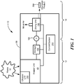
Fig. 1 is a schematic illustration of an organic waste digester system according to the present invention; -
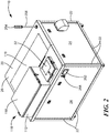
Fig. 2 is a front isometric view of one embodiment of an organic waste digester system; -
Fig. 3 is a rear isometric view of the organic waste digester system ofFig. 2 ; -
Fig. 4 is a front isometric view of the organic waste digester system ofFig. 2 with housing panels removed; -
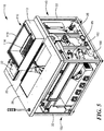
Fig. 5 is a rear isometric view of the organic waste digester system ofFig. 2 with housing panels removed; -
Fig. 6 is an isometric view of a hopper unit of the organic waste digester system ofFig. 2 ; -
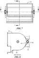
Fig. 7 is a top view of the hopper unit ofFig. 6 ; -
Fig. 8 is a cross-sectional side view of the hopper unit ofFig. 6 along line E-E ofFig. 7 ; -
Fig. 9 is cross-sectional front view of the hopper unit ofFig. 6 along line A-A ofFig. 7 ; -
Fig. 10 is an exploded view of the hopper unit ofFig. 6 ; -
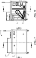
Fig. 11 is a front view of the organic waste digester system ofFig. 2 ; -
Fig. 12 is a side view of the organic waste digester system ofFig. 2 with a side housing panel removed; -
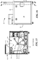
Fig. 13 is a cross-sectional side view of the organic waste digester system ofFig. 2 along line D-D ofFig. 12 ; -
Fig. 14 is a cross-section top view of the organic waste digester system ofFig. 2 along line C-C ofFig. 11 ; -
Fig. 15 is a cross-sectional side view of the organic waste digester system ofFig. 2 along line B-B ofFig. 11 ; -
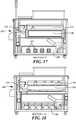
Fig. 16 is a side view of the organic waste digester system ofFig. 2 ; -
Fig. 17 is a cross-sectional view of the organic waste digester system ofFig. 2 along line F-F ofFig. 16 ; -
Fig. 18 is a cross-sectional view of the organic waste digester system ofFig. 2 along the line G-G ofFig. 16 ; -
Fig. 19 is an exploded view of the organic waste digester system ofFig. 2 ; -
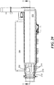
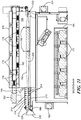
Fig. 20 is a top view of an embodiment of a drying unit in the organic waste digester system ofFig. 2 ; -
Fig. 21 is a cross-sectional view of the drying unit along line H-H ofFig. 20 ; -
Fig. 22 is an elevation view of the drying unit; and -
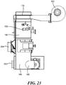
Fig. 23 is a top plan view of the drying unit. - The disclosure of
U.S. Provisional Patent Application No. 62/033,437, filed on August 5, 2014 - An organic waste digester system is provided that can recycle organic waste including raw and cooked fish, meat and poultry, small bones, eggs and egg shells, fruits, vegetables, dairy products, and grain products. In a first stage, the organic waste is degraded and liquefied by heating and mixing. This process is accelerated by the addition of microbes. In a second stage, the liquefied waste is dried and dehydrated. The discharge product is 80-90% dry and reduced in mass by 80-90%. It is stable and can be stored for several months. This discharge product is a compostable material and can be sent to a compositing facility or to a landfill. The discharge product also has uses as an animal feed amendment or a fuel source.
- One embodiment of an organic
waste digester system 10 is illustrated schematically inFig. 1 . The system includes various components comprising thefirst stage 12 andsecond stage 14. In thefirst stage 12,organic waste 16 is introduced into ahopper unit 40. In the hopper unit, the organic waste is heated and mixed in the presence of a microbe mixture to break down into a liquefied sludge. In thesecond stage 14, the liquefied sludge is delivered to adrying unit 150 in which it is dried and dehydrated. The dried sludge is discharged out of the system. Acontrol system 250 in communication with the various components controls the operation of the process and the components of the system, as described further below. - Referring to
Figs. 2-5 and19 , thesystem 10 includes ahousing 20 for housing the system formed of variousstructural framing elements 22 connected to form a frame and covered byside panels 24,lower panel 25, andupper panel 26. Anopening 28, covered with alid 32, in the upper panel of the housing provides access to thehopper unit 40. Organic waste can be deposited directly into thehopper unit 40 through this opening. The system also includes a chopper orgrinder unit 110, described further below. - The
hopper unit 40 includes amain hopper 42 comprising ahopper bin 44, for example of panels of stainless steel welded or otherwise joined and formed into an appropriate bin shape to receive the waste. In the embodiment shown, the hopper bin includes twoside panels 46, twoend panels 48, and abottom panel 52. The bin is supported within thehousing 20 bysuitable framing elements 54. The main hopper also includes anentrance trough 56 having anopen bottom 58 through which the waste is delivered. Waste is deposited into thechopper unit 110, from where it passes through opening 27 into thetrough 56 and then into thehopper bin 44. - A microbe mixture that accelerates the breaking down of the food waste is added directly into the
main hopper 42, for example, through theopening 28, covered by alid 32. The microbe mixture typically can be restocked periodically, such as weekly, monthly, quarterly, or annually. Mixing of the organic waste with the microbe mixture begins breaking down and liquefying the organic waste. Suitable microbe mixtures for the liquefaction of organic waste are known and can be used. The microbes can self-regulate their population based on the food supply. In times of high usage and volume, the microbes reproduce and in times of low volume they slow reproduction and go into a dormant state. Users can also view the level of material in the hopper unit through theopening 28 to ensure that the hopper unit is not overfilled. - The
hopper unit 40 includes alower trough 62 along and below thebottom panel 52. SeeFigs. 6-10 . The bottom panel includesapertures 64 to allow liquid to flow through into thelower trough 62. The lower trough is sloped toward one side of the hopper to allow the sludge (liquefied waste) to flow out into anoutlet 65. An auger orother drive mechanism 66 can be placed in the trough to assist movement of the sludge to the outlet. Contaminants such as glass, ceramics, plastic, hard bones, and the like remain in the hopper bin above thebottom panel 52 and can be removed after the system is shut down. In the embodiment shown, thebottom panel 52 is formed with alarge opening 68 crossed by withslats 72 spaced apart to form theapertures 64. The apertures can be formed in another other manner, such as by providing slits, slots, or holes in the bottom panel or by placing a screen over a large opening in the bottom panel. - The hopper unit also includes an
agitation mechanism 70 to mix the organic waste to help it break down in the presence of the microbe mixture. See alsoFigs. 11-15 . The agitation mechanism includes a number of auger paddles 72 disposed along anagitator drive shaft 74 in a staggered orientation within thebin 44 of themain hopper 42. In one embodiment, eachauger paddle 72 includes ashaft 76 extending orthogonally from the drive shaft to assist the mixing of the food waste. Apaddle 78 is disposed at the end of the shaft. The paddle can have any suitable configuration, such as flat or chevron-shaped.Blades 82 can be disposed along sides of the shaft to help the paddles cut through the organic waste. Eight to ten auger paddles are generally sufficient, although any suitable number can be used, depending on the size of the hopper unit. - The
agitator drive shaft 74 can be driven in any suitable manner such as by amotor 84 mounted on the frame outside of thehopper bin 44. The motor is in communication with thecontrol system 250, which controls operation of the motor to drive theagitation mechanism 70. The motor is connected via a sprocket and chain or abelt 86 andsuitable gearing 88 to the drive shaft. The drive shaft is sealed and supported in a stable manner on the frame, for example, with pillow block bearings and suitable bushings where thedrive shaft 74 enters thehopper bin 44 to keep liquids in the hopper bin from leaking out. Any suitable sealing mechanism that allows stable rotation of the agitator drive shaft while preventing leakage can be used. - The
main hopper 42 can be heated in any suitable manner. For example, a mat heater can be attached directly to the outer surfaces of the panels of the hopper. The hopper is heated to a temperature range of 27 to 49°C (80 to 120°F). The hopper bin can include a layer of an insulating material to retain heat. - Referring also to
Figs. 4-5 ,15 , and19 , thechopper unit 110 initially chops all the organic material, including meat and small bones, that is deposited into the hopper unit, thereby increasing the surface area of the organic waste, which speeds up decomposition. The chopper unit includes ahopper 112 mounted above theopening 27 in thesurface 26 of thehousing 20, and achopping blade mechanism 114 that fits within thetrough 56. Anopening 116 covered with alid 118 provides access to thehopper 112. In one embodiment, thechopping blade mechanism 114 includes a pair of meshing rotary cutters. In another embodiment, the chopping blade mechanism can include a rotary chopper knife formed of a number of individual, stacked rotary blade elements aligned and radially spaced equally about a shaft. Achopper motor 122 spins the blades on the shaft, thereby chopping any organic waste in the chopper hopper into smaller pieces. Thechopper motor 122 is also in communication with thecontrol system 250. The organic waste passing through the chopper unit is discharged through the trough directly into the main hopper. In another embodiment, the chopper unit can be eliminated, if desired, and organic waste can be deposited directly into the hopper bin without an initial chopping. - From the hopper unit, the sludge is pumped by a
pump 160 through suitable hosing or conduits (not shown for clarity) to aninlet 162 of thedrying unit 150 of the second stage to effect drying and dehydrating. SeeFigs. 16-23 . Suitable fittings to which conduits are attached can be provided at theoutlet 65 of the hopper unit and theinlet 162 of the drying unit. A level sensor in the hopper unit can be used to determine when an appropriate amount of sludge is available and to send a signal to the control system, which then engages thepump 160. Thecontrol system 250 then turns on the drying unit to affect the drying and dehydration. The dryingunit 150 can be located within thehousing 20, as shown, or can be external to the housing, for example, adjacent to the housing or on top of the housing. Optionally, a storage vessel 159 (seeFig. 1 ) can be provided to store the sludge (the liquefied waste) as it is removed from the hopper before transfer to the drying unit. - The drying
unit 150 heats the liquefied sludge to a temperature within a range of 102 to 149°C (215 to 300°F), which is sufficient to effectively kill pathogens, bacteria, and seeds. In one embodiment, adrying unit 150 uses microwave energy to effect the drying of the sludge. Referring toFigs. 16-23 , the drying unit includes amicrowave generation chamber 170 for supporting and housing one ormore microwave units 172, in communication with thecontrol system 250, amicrowave application chamber 190 through which the sludge is transported, for example, on aconveyor belt 192, while being heated by application of the microwave energy, and amicrowave suppression chamber 210 at the outlet of the application chamber. Eachmicrowave unit 172 includes ahigh voltage transformer 174 and associatedmagnetron tube 176 andwaveguide 178. The waveguides are disposed to direct microwave energy through awall 182, such as a floor in the embodiment shown, into themicrowave application chamber 190. In the embodiment shown, themicrowave generation chamber 170 housing the magnetron tubes and waveguides is disposed above themicrowave application chamber 190, while the associated transformers are housed in a separatepower plant enclosure 184 below the application chamber for better control of the high heat generated. However, other configurations can be used if desired, such as placing the microwave application enclosure alongside or above the microwave generation chamber, and/or placing the transformers within the same chamber as the magnetron tubes and waveguides. - The
microwave suppression chamber 210 at the outlet of the microwave application chamber prevents microwave radiation from leaking out of the application chamber. The suppression chamber includes anupper wall 212 andlower wall 213 supporting an appropriate number of suppression pins 214 extending into the chamber. The pins are of any suitable number, size, and spacing depending on the frequency of the microwaves generated to suppress the microwave radiation. Other suppression configurations can be used. The conveyor belt extends through the suppression chamber to transport the dried sludge so that it can be discharged out of the drying unit. The conveyor belt returns below thelower wall 213 and through an opening between the suppression chamber and the application chamber. - One or more cooling fans or
blowers 202 are disposed to draw cool air into the drying unit to cool the microwave generation enclosure, the power plant enclosure, and the microwave suppression chamber. The fans can be disposed in any suitable wall or walls, such as a side wall or ceiling. The ambient air within the microwave generation chamber is heated as a byproduct of cooling the magnetrons. The heated air can be introduced into the microwave application chamber, for example, through the microwave waveguides. The waveguides can include a grate or another suitable opening for the heated ambient air to pass through. Anexhaust fan 204 is also provided to exhaust air from the drying unit. Any suitable number of cooling fans and exhaust fans can be used. - In one example, the
microwave drying unit 150 operates at 2400 MHz frequency, 220 V, 3 phase AC current at 9.6 kilowatts total power. Any suitable number of microwave units can be used, depending on, for example, the application and the amount of material to be digested. In one embodiment, nine microwave units are used. Similarly, any suitable convective and/or forced cooling arrangement of the magnetrons can be used. - The sludge to be dried passes through the
microwave application chamber 190 andsuppression chamber 210 in any suitable manner. For example, aconveyor belt 192 can be provided that travels the length of the application chamber. The sludge enters the application chamber through aninlet 162 and is deposited onto the conveyor belt. The inlet can include, for example, a tube fitting connected to a conduit from thepump 160. The sludge passes along, for example, beneath, the row ofwaveguides 178 of the microwave units, which directs microwave energy and heated air onto the sludge. The sludge is thereby heated by radiative heating and convective heating to effect the drying. - A temperature sensor 194 (see
Fig. 21 ) is disposed in the application chamber near the output end. In one example, an infrared temperature sensor is used to monitor the temperature of the sludge as it exits the conveyor belt. The temperature of the sludge is roughly analogous to the final moisture content of the sludge. The particular correlation depends on the type of organic waste that is introduced into the system, and can be readily determined by testing. For example, in one example, a temperature of at least 171°C (340°F) indicates a moisture content of no more than 10%. The type of organic waste is generally consistent at a particular location, and thus once a correlation between temperature and moisture content has been determined for that location, the temperature can serve as a suitable determination of the moisture content. For most applications, the moisture content of the sludge as it is discharged from the application chamber is in the range of 10 to 13%. It will be appreciated that the moisture content can vary, for example, from a low of 1%, 2%, 3%, 4%, 5%, 6%, 7%, 8%, 9%, or 10% to a high of 13%, 14%, 15%, 20% or 25%. The temperature sensor is in communication with the control system, which can control each of the microwave units individually to provide a desired amount of heating. For example, the control system can operate the microwave units closest to the inlet end of the application chamber at a higher power to provide a greater amount of heating to the sludge. The microwave units nearer the outlet end can be operated as needed, depending on the moisture content of the sludge. - The
conveyor belt 192 is formed of a soft material that is able to be formed with a cupped shape in transverse cross section at and near the inlet end of the application chamber. The cupped shaped is formed by side guards 196 (shown schematically inFig. 21 ). The entering sludge still has a high moisture content, and the cupped shape of the conveyor belt retains the water within the longitudinal edges of the belt while the sludge is heated and the water evaporates. The belt is also solid, so that liquids and solid particulates cannot fall through. As the sludge dries and is transported toward the outlet end of the application chamber, the conveyor belt takes on a flat configuration, such that it is substantially flat at the discharge end. The flat configuration of the belt at the discharge end allows the sludge to be more readily removed from the conveyor belt, for example, with a blade, knife, orscraper 198 at the discharge end the belt. In one embodiment, a cutting blade orknife 198, operable by amotor 199 in communication with thecontrol system 250, is provided at the discharge end of the belt to cut the sludge into blocks or segments. - The conveyor belt includes any suitable driving mechanism, such as a
drive roller 222,motor 224, areturn roller 226, and tensioning mechanism. Anidler roller 228 can be provided to flatten the belt. A suitable material for the belt is a silicone material, which can be repeatedly deformed into a cupped configuration at the entrance and then flattened at the discharge end as the belt cycles through the application chamber. - At the outlet end of the suppression chamber, the conveyor belt deposits the sludge into an
outlet duct 230. The driedsludge 300 can be collected and transported to a collection device. - In some embodiments, the outlet duct can be in communication with a vacuum source to assist in pulling the dried sludge off the conveyor belt and into and through the outlet duct. Process air in the application chamber is also vented through the exhaust duct.
- In a further embodiment, exhaust products from the application chamber, containing dry particles and moist process air, can be conveyed via a vacuum system into a collection canister. The process air can be filtered to remove any suspended particles and exhausted to ambient through a vacuum blower. In a still further embodiment, the process air can be transmitted to an air dryer or dehumidifier that removes moisture before discharging the dehumidified air to ambient.
- The
control system 250 can be located in apanel 260 that also houses the electrical wiring, fuses, circuit breakers, and the like. In one embodiment, thecontrol system 250 is a programmable logic controller. The control system includes adisplay 252 with an operator input device such as a keypad and a display screen for outputting messages. The control system can be programmed to indicate any stoppages, failures, errors, or maintenance needs. A cut-off switch can be provided so that, when themain hopper lid 32, thechopper lid 118, or anaccess panel 119 is opened during operation, the unit shuts off. A visual indicator light orlights 254 can be provided to illuminate when the main hopper lid and/or the chopper lid are open. In one embodiment, lights are provided on a pole 256 elevated above the housing so that they are readily visible. Anemergency stop button 258 can be located in a relatively accessible location on the outside of the unit. - The present organic waste digester system is able to maintain optimum levels of aeration, moisture and temperature during the digesting process. The system is selfcontained and organic waste can be continually added. The cycle time from initial input of organic waste to the discharge of a compostable material can be as little as 3.5 hours. The system does not require the addition of water and does not need to be plumbed into an existing water supply. The organic waste digester system does not discharge gray water. No liquid waste is produced during the evaporation process.
- The present invention has been described with reference to the preferred embodiments. It is to be understood that the invention is not limited to the exact details of construction, operation, exact materials or embodiments shown and described, as obvious modifications will be apparent to one skilled in the art. It is believed that many modifications and alterations to the embodiments disclosed will readily suggest themselves to those skilled in the art upon reading and understanding the detailed description of the invention. It is intended to include all such modifications and alterations insofar as they come within the scope of the claims.
Claims (13)
- An organic waste digester system, comprising:a hopper unit (40), the hopper unit including a bin (44) to receive organic waste, an agitation mechanism (70) to mix the organic waste, a heater to heat the organic waste within the bin, and an outlet (65) through which liquefied organic waste is discharged;a drying unit (150) downstream of the hopper unit to receive and dry the liquefied organic waste from the hopper unit, the drying unit comprising:a microwave drying unit, wherein the microwave drying unit comprises a microwave generation chamber (170) and a microwave application chamber (190), wherein the microwave generation chamber includes a plurality of microwave units (172), each microwave unit including a waveguide (178) disposed to direct microwave radiation into the microwave application chamber, anda conveyor (192) disposed to travel through the microwave application chamber, the conveyor configured to receive the liquefied organic waste from the hopper unit.
- The system of claim 1, further comprising one or more cooling fans (202) in the microwave generation chamber to cool the microwave units.
- The system of claim 1, further comprising one or more openings between the microwave generation chamber and the microwave application chamber to direct heated air into the microwave application chamber.
- The system of claim 3, wherein the one or more openings are disposed through an associated waveguide (178).
- The system of claim 1, further comprising a microwave suppression chamber (210) disposed at an outlet of the microwave application chamber, wherein the conveyor is disposed to travel through the microwave suppression chamber.
- The system of claim 1, wherein the conveyor comprises a conveyor belt having a cupped shape in transverse cross-section at an inlet end of the microwave drying unit and a flat configuration at an outlet end of the microwave drying unit.
- The system of claim 6, further comprising an outlet duct disposed at an outlet end of the microwave drying unit to receive organic waste, and a blade (198) disposed to scrape organic waste off the conveyor into the outlet duct.
- The system of claim 7, further comprising a vacuum source disposed to exert a negative pressure at the outlet duct.
- The system of claim 1, further comprising an exhaust duct disposed at an outlet end of the microwave drying unit configured to remove exhaust products from the microwave drying unit, and a filter on the exhaust duct to remove suspended particles.
- The system of claim 9, further comprising a collection canister on the exhaust duct to receive dry particles.
- The system of claim 9, further comprising a dehumidifier on the exhaust duct to remove moisture from process air.
- The system of claim 1, further comprising a control system (250) in communication with the hopper unit and the drying unit, and a chopper hopper (112) and a chopping mechanism (114) disposed at an entrance to the bin of the hopper unit.
- The system of claim 1, wherein the heater is operative to heat the bin to a temperature range of 27 to 49°C (80 to 120°F), and further comprising a microbe mixture to accelerate breakdown of the organic waste within the bin.
Applications Claiming Priority (2)
| Application Number | Priority Date | Filing Date | Title |
|---|---|---|---|
| US201462033437P | 2014-08-05 | 2014-08-05 | |
| PCT/US2015/033212 WO2016022198A1 (en) | 2014-08-05 | 2015-05-29 | Organic waste digester system |
Publications (3)
| Publication Number | Publication Date |
|---|---|
| EP3186018A1 EP3186018A1 (en) | 2017-07-05 |
| EP3186018A4 EP3186018A4 (en) | 2018-03-21 |
| EP3186018B1 true EP3186018B1 (en) | 2021-09-01 |
Family
ID=55264297
Family Applications (1)
| Application Number | Title | Priority Date | Filing Date |
|---|---|---|---|
| EP15830090.5A Not-in-force EP3186018B1 (en) | 2014-08-05 | 2015-05-29 | Organic waste digester system |
Country Status (4)
| Country | Link |
|---|---|
| US (1) | US10563165B2 (en) |
| EP (1) | EP3186018B1 (en) |
| CA (1) | CA2994390C (en) |
| WO (1) | WO2016022198A1 (en) |
Families Citing this family (16)
| Publication number | Priority date | Publication date | Assignee | Title |
|---|---|---|---|---|
| CN104230400B (en) * | 2014-09-16 | 2016-09-14 | 中国环境科学研究院 | A kind of kitchen castoff quick resource processing equipment |
| DE102016114043B3 (en) * | 2016-07-29 | 2017-08-10 | Technische Universität Dresden | Device for isolating stem cells from fetal tissues |
| CN108393327B (en) * | 2018-02-08 | 2020-12-29 | 衢州学院 | garbage disposal machine |
| IT201800000548A1 (en) * | 2018-03-02 | 2019-09-02 | Emanuele Montalbano | MOBILE PLANT FOR THE BIOSTABILIZATION AND COMPOSTING OF THE ORGANIC FRACTION ARISING FROM INDUSTRIAL WASTE, SEPARATE COLLECTION (MAYBE) AND FROM THE MECHANICAL TREATMENT OF UNDIFFERENTIATED WASTE |
| US10906046B2 (en) | 2019-05-07 | 2021-02-02 | Food Cycle Science Corporation | System and method for infusion and desiccation of foodstuffs |
| US12251705B2 (en) | 2019-05-07 | 2025-03-18 | Food Cycle Science Corporation | System and method for providing a food recycler having a bucket and grinder for processing food |
| GB2591123B (en) * | 2020-01-16 | 2023-01-18 | Rdc Tech Ltd | An apparatus to effect at least partial breakdown of a material or product item or a combination of materials or product items |
| CN111530899B (en) * | 2020-05-29 | 2024-06-21 | 桂林益克垃环保科技有限公司 | Integrated multifunctional household garbage treatment equipment |
| CN112226261B (en) * | 2020-10-12 | 2021-06-04 | 新宁新欣热能科技有限公司 | Production method of biological granular fuel |
| US11780749B2 (en) * | 2020-12-10 | 2023-10-10 | John Otis Farneman | Electromagnetic energy system for the breakdown and destruction of organic waste |
| JP7505131B2 (en) | 2021-05-27 | 2024-06-24 | バイオグリーン 360 インク. | Organic Waste Management System |
| US12530662B2 (en) | 2021-09-01 | 2026-01-20 | Chewie Labs Llc | Network-connected apparatus promoting environmentally responsible processing and disposition of organic matter data |
| WO2023034186A1 (en) | 2021-09-01 | 2023-03-09 | Mill Industries, LLC | Integrating intelligent sensing and safety assurance into organic matter processing apparatus |
| US12427556B2 (en) | 2021-09-01 | 2025-09-30 | Chewie Labs Llc | User-removable, electrically heated, and mechanically actuated bucket unit for organic matter processing apparatus |
| US12454408B2 (en) | 2021-09-01 | 2025-10-28 | Chewie Labs Llc | Apparatus for processing organic matter having lid and air treatment system promoting pleasant user experience |
| US12098108B2 (en) | 2021-09-01 | 2024-09-24 | Chewie Labs Llc | Intelligent sensor-driven processing of organic matter for the smart home |
Family Cites Families (29)
| Publication number | Priority date | Publication date | Assignee | Title |
|---|---|---|---|---|
| US3233976A (en) | 1959-11-24 | 1966-02-08 | Waste Processes Inc | Apparatus for converting waste material into fertilizer |
| US3872603A (en) * | 1968-01-30 | 1975-03-25 | Varian Associates | Apparatus for drying materials employing spaced microwave heating and transverse-flow moisture flushing stations |
| FR2008824B1 (en) * | 1968-05-18 | 1975-10-03 | Kurashiki Rayon Co | |
| US3590202A (en) * | 1970-02-24 | 1971-06-29 | Bechtel Corp | Construction for tuning microwave heating applicator |
| US4035598A (en) * | 1974-10-22 | 1977-07-12 | Johannes Menschner Maschinenfabrik Gmbh & Co. Kg. | Apparatus for thermally treating polymeric workpieces with microwave energy |
| US5028010A (en) * | 1989-12-18 | 1991-07-02 | Itex Enterprises, Inc. | Apparatus for mixing solid or semi-solid wastes with additives |
| KR960015463B1 (en) * | 1992-06-01 | 1996-11-14 | 마쯔시다덴기산교 가부시기가이샤 | High frequency heating device |
| DE4241754C1 (en) * | 1992-12-11 | 1994-04-07 | Ikotek Informatik Kommunikat | Process for processing secondary raw materials from waste and plant for carrying out the process |
| JP3303892B2 (en) * | 1993-07-12 | 2002-07-22 | 中部ドラム罐工業株式会社 | High-speed fermentation processing equipment for garbage |
| JPH07157386A (en) * | 1993-12-01 | 1995-06-20 | Toyo Dynam Kk | Method and apparatus for treating organic waste |
| US5980823A (en) * | 1996-05-27 | 1999-11-09 | Jidosha Buhin Kogyo Co., Ltd. | Garbage processing apparatus having deodorizing unit |
| US6139744A (en) * | 1997-07-05 | 2000-10-31 | Microseptec, Inc. | Waste treatment device and method employing the same |
| US6224646B1 (en) * | 1997-10-17 | 2001-05-01 | Manitoba Ltd. | Waste treatment system |
| HUP0102804A2 (en) | 1998-07-01 | 2001-12-28 | The Procter & Gamble Co. | Process for removing water from fibrous web using oscillatory flow-reversing impingement gas |
| US20020030012A1 (en) | 2000-04-19 | 2002-03-14 | Sullivan John Michael | Comprehensive waste treatment system and related methods for animal feeding operations to effectively recover waste solids for beneficial re-use and for treatment of wastewater for nutrient removal and recycle, re-use or discharge |
| US8981250B2 (en) | 2001-07-16 | 2015-03-17 | Foret Plasma Labs, Llc | Apparatus for treating a substance with wave energy from plasma and an electrical Arc |
| US6675958B2 (en) * | 2001-08-15 | 2004-01-13 | Kaeb Sales Inc. | Tube conveyor |
| WO2004049787A2 (en) | 2002-11-25 | 2004-06-17 | Sheets Sr Richard G | Animal waste effluent treatment |
| US7002122B2 (en) * | 2003-10-24 | 2006-02-21 | The Ferrite Company, Inc. | Choke assembly for continuous conveyor microwave oven |
| KR100541159B1 (en) * | 2004-03-02 | 2006-01-10 | (주)대우건설 | Sewage sludge treatment apparatus and method using microwave and heating |
| US20060049185A1 (en) * | 2004-08-23 | 2006-03-09 | Masson Randall S | Conveyor belt configurations for microwave oven |
| SE529368C2 (en) * | 2005-10-07 | 2007-07-17 | Metso Minerals Wear Prot Ab | Scraper blades and process for manufacturing such |
| EP2139827A1 (en) * | 2007-04-13 | 2010-01-06 | Tecnoimpianti SRL | Plant and process for transformation of organic material |
| GB2462651B (en) * | 2008-08-15 | 2010-10-06 | Advasol Man Ltd | Method and apparatus for in-vessel composting and digestion of biodegradable waste |
| US20110179841A1 (en) * | 2010-01-27 | 2011-07-28 | James Cheng-Shyong Lu | High-rate composting process and equipment |
| CA2801429C (en) * | 2010-04-23 | 2018-06-12 | Organic Fuel Technology A/S | Process for the production of biofuel |
| US20130089918A1 (en) * | 2010-07-08 | 2013-04-11 | Bio-Cosmo Technologies Limited | Food Waste Digestion System |
| MX2011009257A (en) | 2010-07-13 | 2012-10-02 | Ecologico Logic Inc | SOLID WASTE DIGESTION SYSTEM. |
| US9603203B2 (en) * | 2013-11-26 | 2017-03-21 | Industrial Microwave Systems, L.L.C. | Tubular waveguide applicator |
-
2015
- 2015-05-29 WO PCT/US2015/033212 patent/WO2016022198A1/en not_active Ceased
- 2015-05-29 US US15/501,595 patent/US10563165B2/en not_active Expired - Fee Related
- 2015-05-29 EP EP15830090.5A patent/EP3186018B1/en not_active Not-in-force
- 2015-05-29 CA CA2994390A patent/CA2994390C/en active Active
Also Published As
| Publication number | Publication date |
|---|---|
| EP3186018A1 (en) | 2017-07-05 |
| WO2016022198A1 (en) | 2016-02-11 |
| US10563165B2 (en) | 2020-02-18 |
| US20170226466A1 (en) | 2017-08-10 |
| CA2994390C (en) | 2022-08-16 |
| CA2994390A1 (en) | 2016-02-11 |
| EP3186018A4 (en) | 2018-03-21 |
Similar Documents
| Publication | Publication Date | Title |
|---|---|---|
| CA2994390C (en) | Organic waste digester system | |
| KR200490770Y1 (en) | a transferring screw of food waste processing device | |
| JP2004222589A (en) | Apparatus and method for draining and drying edible vegetable dishes | |
| GB2232594A (en) | Treating medical hazardous wastes | |
| WO2016043656A1 (en) | Apparatus for treating food waste | |
| KR20240035952A (en) | Microwave Waste Heating Systems and Related Features | |
| JP3659397B2 (en) | Drying apparatus and drying method thereof | |
| WO2022250663A1 (en) | Microwave waste heating system | |
| KR101680957B1 (en) | Solid fuel manufacturing apparatus and method for manufacturing solid fuel | |
| KR101273490B1 (en) | A feed manufacturing facility which utilize food waste | |
| KR20120111162A (en) | Apparatus for producing of organic fertilizer using fishes | |
| CN202427704U (en) | Treatment system for food wastes | |
| JP2004503262A (en) | Method and apparatus for sterilizing and / or sterilizing a growth medium | |
| CN218202578U (en) | Biomass garbage resource conversion equipment | |
| KR101730971B1 (en) | Rapid Manufacturing System for Low Salt Kimchi | |
| CN203159493U (en) | A natural aerobic composting equipment for organic waste | |
| KR100722788B1 (en) | Food Waste Disposal Device | |
| KR102194977B1 (en) | Food garbage treatment apparatus | |
| KR100851956B1 (en) | Waste disposal equipment | |
| KR100757401B1 (en) | Food Waste Crushing Dryer | |
| KR20230047283A (en) | Organic matter disposal apparatus | |
| KR20020035682A (en) | A system which makes provenders for food wastes | |
| RU2820685C1 (en) | Meat wastes dryer with microwave energy supply to electrically driven cylindrical sieve resonator | |
| CN114349546A (en) | Organic matter degradation treatment method and device | |
| KR101286856B1 (en) | Transfer carrier of food treaterer and dry device of food treaterer using the same |
Legal Events
| Date | Code | Title | Description |
|---|---|---|---|
| STAA | Information on the status of an ep patent application or granted ep patent |
Free format text: STATUS: THE INTERNATIONAL PUBLICATION HAS BEEN MADE |
|
| PUAI | Public reference made under article 153(3) epc to a published international application that has entered the european phase |
Free format text: ORIGINAL CODE: 0009012 |
|
| STAA | Information on the status of an ep patent application or granted ep patent |
Free format text: STATUS: REQUEST FOR EXAMINATION WAS MADE |
|
| 17P | Request for examination filed |
Effective date: 20170301 |
|
| AK | Designated contracting states |
Kind code of ref document: A1 Designated state(s): AL AT BE BG CH CY CZ DE DK EE ES FI FR GB GR HR HU IE IS IT LI LT LU LV MC MK MT NL NO PL PT RO RS SE SI SK SM TR |
|
| AX | Request for extension of the european patent |
Extension state: BA ME |
|
| DAV | Request for validation of the european patent (deleted) | ||
| DAX | Request for extension of the european patent (deleted) | ||
| RIN1 | Information on inventor provided before grant (corrected) |
Inventor name: GRILLO, PAUL Inventor name: SECOVICH, BRUCE |
|
| A4 | Supplementary search report drawn up and despatched |
Effective date: 20180220 |
|
| RIC1 | Information provided on ipc code assigned before grant |
Ipc: C05F 17/02 20060101ALI20180214BHEP Ipc: C05F 17/00 20060101ALI20180214BHEP Ipc: C05F 9/02 20060101ALI20180214BHEP Ipc: B09B 3/00 20060101AFI20180214BHEP |
|
| STAA | Information on the status of an ep patent application or granted ep patent |
Free format text: STATUS: EXAMINATION IS IN PROGRESS |
|
| 17Q | First examination report despatched |
Effective date: 20200124 |
|
| GRAP | Despatch of communication of intention to grant a patent |
Free format text: ORIGINAL CODE: EPIDOSNIGR1 |
|
| STAA | Information on the status of an ep patent application or granted ep patent |
Free format text: STATUS: GRANT OF PATENT IS INTENDED |
|
| RIC1 | Information provided on ipc code assigned before grant |
Ipc: C05F 9/02 20060101ALI20210311BHEP Ipc: C05B 11/08 20060101ALI20210311BHEP Ipc: B09B 3/00 20060101AFI20210311BHEP |
|
| INTG | Intention to grant announced |
Effective date: 20210408 |
|
| GRAS | Grant fee paid |
Free format text: ORIGINAL CODE: EPIDOSNIGR3 |
|
| GRAF | Information related to payment of grant fee modified |
Free format text: ORIGINAL CODE: EPIDOSCIGR3 |
|
| GRAA | (expected) grant |
Free format text: ORIGINAL CODE: 0009210 |
|
| STAA | Information on the status of an ep patent application or granted ep patent |
Free format text: STATUS: THE PATENT HAS BEEN GRANTED |
|
| AK | Designated contracting states |
Kind code of ref document: B1 Designated state(s): AL AT BE BG CH CY CZ DE DK EE ES FI FR GB GR HR HU IE IS IT LI LT LU LV MC MK MT NL NO PL PT RO RS SE SI SK SM TR |
|
| REG | Reference to a national code |
Ref country code: GB Ref legal event code: FG4D |
|
| REG | Reference to a national code |
Ref country code: CH Ref legal event code: EP Ref country code: AT Ref legal event code: REF Ref document number: 1425672 Country of ref document: AT Kind code of ref document: T Effective date: 20210915 |
|
| REG | Reference to a national code |
Ref country code: DE Ref legal event code: R096 Ref document number: 602015072950 Country of ref document: DE |
|
| REG | Reference to a national code |
Ref country code: IE Ref legal event code: FG4D |
|
| REG | Reference to a national code |
Ref country code: LT Ref legal event code: MG9D |
|
| REG | Reference to a national code |
Ref country code: NL Ref legal event code: MP Effective date: 20210901 |
|
| PG25 | Lapsed in a contracting state [announced via postgrant information from national office to epo] |
Ref country code: HR Free format text: LAPSE BECAUSE OF FAILURE TO SUBMIT A TRANSLATION OF THE DESCRIPTION OR TO PAY THE FEE WITHIN THE PRESCRIBED TIME-LIMIT Effective date: 20210901 Ref country code: SE Free format text: LAPSE BECAUSE OF FAILURE TO SUBMIT A TRANSLATION OF THE DESCRIPTION OR TO PAY THE FEE WITHIN THE PRESCRIBED TIME-LIMIT Effective date: 20210901 Ref country code: RS Free format text: LAPSE BECAUSE OF FAILURE TO SUBMIT A TRANSLATION OF THE DESCRIPTION OR TO PAY THE FEE WITHIN THE PRESCRIBED TIME-LIMIT Effective date: 20210901 Ref country code: LT Free format text: LAPSE BECAUSE OF FAILURE TO SUBMIT A TRANSLATION OF THE DESCRIPTION OR TO PAY THE FEE WITHIN THE PRESCRIBED TIME-LIMIT Effective date: 20210901 Ref country code: BG Free format text: LAPSE BECAUSE OF FAILURE TO SUBMIT A TRANSLATION OF THE DESCRIPTION OR TO PAY THE FEE WITHIN THE PRESCRIBED TIME-LIMIT Effective date: 20211201 Ref country code: NO Free format text: LAPSE BECAUSE OF FAILURE TO SUBMIT A TRANSLATION OF THE DESCRIPTION OR TO PAY THE FEE WITHIN THE PRESCRIBED TIME-LIMIT Effective date: 20211201 Ref country code: FI Free format text: LAPSE BECAUSE OF FAILURE TO SUBMIT A TRANSLATION OF THE DESCRIPTION OR TO PAY THE FEE WITHIN THE PRESCRIBED TIME-LIMIT Effective date: 20210901 Ref country code: ES Free format text: LAPSE BECAUSE OF FAILURE TO SUBMIT A TRANSLATION OF THE DESCRIPTION OR TO PAY THE FEE WITHIN THE PRESCRIBED TIME-LIMIT Effective date: 20210901 |
|
| REG | Reference to a national code |
Ref country code: AT Ref legal event code: MK05 Ref document number: 1425672 Country of ref document: AT Kind code of ref document: T Effective date: 20210901 |
|
| PG25 | Lapsed in a contracting state [announced via postgrant information from national office to epo] |
Ref country code: PL Free format text: LAPSE BECAUSE OF FAILURE TO SUBMIT A TRANSLATION OF THE DESCRIPTION OR TO PAY THE FEE WITHIN THE PRESCRIBED TIME-LIMIT Effective date: 20210901 Ref country code: LV Free format text: LAPSE BECAUSE OF FAILURE TO SUBMIT A TRANSLATION OF THE DESCRIPTION OR TO PAY THE FEE WITHIN THE PRESCRIBED TIME-LIMIT Effective date: 20210901 Ref country code: GR Free format text: LAPSE BECAUSE OF FAILURE TO SUBMIT A TRANSLATION OF THE DESCRIPTION OR TO PAY THE FEE WITHIN THE PRESCRIBED TIME-LIMIT Effective date: 20211202 |
|
| PG25 | Lapsed in a contracting state [announced via postgrant information from national office to epo] |
Ref country code: AT Free format text: LAPSE BECAUSE OF FAILURE TO SUBMIT A TRANSLATION OF THE DESCRIPTION OR TO PAY THE FEE WITHIN THE PRESCRIBED TIME-LIMIT Effective date: 20210901 |
|
| PG25 | Lapsed in a contracting state [announced via postgrant information from national office to epo] |
Ref country code: IS Free format text: LAPSE BECAUSE OF FAILURE TO SUBMIT A TRANSLATION OF THE DESCRIPTION OR TO PAY THE FEE WITHIN THE PRESCRIBED TIME-LIMIT Effective date: 20220101 Ref country code: SM Free format text: LAPSE BECAUSE OF FAILURE TO SUBMIT A TRANSLATION OF THE DESCRIPTION OR TO PAY THE FEE WITHIN THE PRESCRIBED TIME-LIMIT Effective date: 20210901 Ref country code: SK Free format text: LAPSE BECAUSE OF FAILURE TO SUBMIT A TRANSLATION OF THE DESCRIPTION OR TO PAY THE FEE WITHIN THE PRESCRIBED TIME-LIMIT Effective date: 20210901 Ref country code: RO Free format text: LAPSE BECAUSE OF FAILURE TO SUBMIT A TRANSLATION OF THE DESCRIPTION OR TO PAY THE FEE WITHIN THE PRESCRIBED TIME-LIMIT Effective date: 20210901 Ref country code: PT Free format text: LAPSE BECAUSE OF FAILURE TO SUBMIT A TRANSLATION OF THE DESCRIPTION OR TO PAY THE FEE WITHIN THE PRESCRIBED TIME-LIMIT Effective date: 20220103 Ref country code: NL Free format text: LAPSE BECAUSE OF FAILURE TO SUBMIT A TRANSLATION OF THE DESCRIPTION OR TO PAY THE FEE WITHIN THE PRESCRIBED TIME-LIMIT Effective date: 20210901 Ref country code: EE Free format text: LAPSE BECAUSE OF FAILURE TO SUBMIT A TRANSLATION OF THE DESCRIPTION OR TO PAY THE FEE WITHIN THE PRESCRIBED TIME-LIMIT Effective date: 20210901 Ref country code: CZ Free format text: LAPSE BECAUSE OF FAILURE TO SUBMIT A TRANSLATION OF THE DESCRIPTION OR TO PAY THE FEE WITHIN THE PRESCRIBED TIME-LIMIT Effective date: 20210901 Ref country code: AL Free format text: LAPSE BECAUSE OF FAILURE TO SUBMIT A TRANSLATION OF THE DESCRIPTION OR TO PAY THE FEE WITHIN THE PRESCRIBED TIME-LIMIT Effective date: 20210901 |
|
| REG | Reference to a national code |
Ref country code: DE Ref legal event code: R097 Ref document number: 602015072950 Country of ref document: DE |
|
| PLBE | No opposition filed within time limit |
Free format text: ORIGINAL CODE: 0009261 |
|
| STAA | Information on the status of an ep patent application or granted ep patent |
Free format text: STATUS: NO OPPOSITION FILED WITHIN TIME LIMIT |
|
| PG25 | Lapsed in a contracting state [announced via postgrant information from national office to epo] |
Ref country code: IT Free format text: LAPSE BECAUSE OF FAILURE TO SUBMIT A TRANSLATION OF THE DESCRIPTION OR TO PAY THE FEE WITHIN THE PRESCRIBED TIME-LIMIT Effective date: 20210901 Ref country code: DK Free format text: LAPSE BECAUSE OF FAILURE TO SUBMIT A TRANSLATION OF THE DESCRIPTION OR TO PAY THE FEE WITHIN THE PRESCRIBED TIME-LIMIT Effective date: 20210901 |
|
| PGFP | Annual fee paid to national office [announced via postgrant information from national office to epo] |
Ref country code: GB Payment date: 20220527 Year of fee payment: 8 Ref country code: FR Payment date: 20220525 Year of fee payment: 8 Ref country code: DE Payment date: 20220527 Year of fee payment: 8 |
|
| 26N | No opposition filed |
Effective date: 20220602 |
|
| PG25 | Lapsed in a contracting state [announced via postgrant information from national office to epo] |
Ref country code: SI Free format text: LAPSE BECAUSE OF FAILURE TO SUBMIT A TRANSLATION OF THE DESCRIPTION OR TO PAY THE FEE WITHIN THE PRESCRIBED TIME-LIMIT Effective date: 20210901 |
|
| REG | Reference to a national code |
Ref country code: CH Ref legal event code: PL |
|
| REG | Reference to a national code |
Ref country code: BE Ref legal event code: MM Effective date: 20220531 |
|
| PG25 | Lapsed in a contracting state [announced via postgrant information from national office to epo] |
Ref country code: MC Free format text: LAPSE BECAUSE OF FAILURE TO SUBMIT A TRANSLATION OF THE DESCRIPTION OR TO PAY THE FEE WITHIN THE PRESCRIBED TIME-LIMIT Effective date: 20210901 Ref country code: LU Free format text: LAPSE BECAUSE OF NON-PAYMENT OF DUE FEES Effective date: 20220529 Ref country code: LI Free format text: LAPSE BECAUSE OF NON-PAYMENT OF DUE FEES Effective date: 20220531 Ref country code: CH Free format text: LAPSE BECAUSE OF NON-PAYMENT OF DUE FEES Effective date: 20220531 |
|
| PG25 | Lapsed in a contracting state [announced via postgrant information from national office to epo] |
Ref country code: IE Free format text: LAPSE BECAUSE OF NON-PAYMENT OF DUE FEES Effective date: 20220529 |
|
| PG25 | Lapsed in a contracting state [announced via postgrant information from national office to epo] |
Ref country code: BE Free format text: LAPSE BECAUSE OF NON-PAYMENT OF DUE FEES Effective date: 20220531 |
|
| P01 | Opt-out of the competence of the unified patent court (upc) registered |
Effective date: 20230519 |
|
| REG | Reference to a national code |
Ref country code: DE Ref legal event code: R119 Ref document number: 602015072950 Country of ref document: DE |
|
| GBPC | Gb: european patent ceased through non-payment of renewal fee |
Effective date: 20230529 |
|
| PG25 | Lapsed in a contracting state [announced via postgrant information from national office to epo] |
Ref country code: HU Free format text: LAPSE BECAUSE OF FAILURE TO SUBMIT A TRANSLATION OF THE DESCRIPTION OR TO PAY THE FEE WITHIN THE PRESCRIBED TIME-LIMIT; INVALID AB INITIO Effective date: 20150529 |
|
| PG25 | Lapsed in a contracting state [announced via postgrant information from national office to epo] |
Ref country code: MK Free format text: LAPSE BECAUSE OF FAILURE TO SUBMIT A TRANSLATION OF THE DESCRIPTION OR TO PAY THE FEE WITHIN THE PRESCRIBED TIME-LIMIT Effective date: 20210901 Ref country code: DE Free format text: LAPSE BECAUSE OF NON-PAYMENT OF DUE FEES Effective date: 20231201 Ref country code: CY Free format text: LAPSE BECAUSE OF FAILURE TO SUBMIT A TRANSLATION OF THE DESCRIPTION OR TO PAY THE FEE WITHIN THE PRESCRIBED TIME-LIMIT Effective date: 20210901 Ref country code: GB Free format text: LAPSE BECAUSE OF NON-PAYMENT OF DUE FEES Effective date: 20230529 |
|
| PG25 | Lapsed in a contracting state [announced via postgrant information from national office to epo] |
Ref country code: FR Free format text: LAPSE BECAUSE OF NON-PAYMENT OF DUE FEES Effective date: 20230531 |
|
| PG25 | Lapsed in a contracting state [announced via postgrant information from national office to epo] |
Ref country code: MT Free format text: LAPSE BECAUSE OF FAILURE TO SUBMIT A TRANSLATION OF THE DESCRIPTION OR TO PAY THE FEE WITHIN THE PRESCRIBED TIME-LIMIT Effective date: 20210901 |
|
| PG25 | Lapsed in a contracting state [announced via postgrant information from national office to epo] |
Ref country code: TR Free format text: LAPSE BECAUSE OF FAILURE TO SUBMIT A TRANSLATION OF THE DESCRIPTION OR TO PAY THE FEE WITHIN THE PRESCRIBED TIME-LIMIT Effective date: 20210901 |