EP3184947A1 - Blast furnace stockhouse material storage arrangement - Google Patents
Blast furnace stockhouse material storage arrangement Download PDFInfo
- Publication number
- EP3184947A1 EP3184947A1 EP15202150.7A EP15202150A EP3184947A1 EP 3184947 A1 EP3184947 A1 EP 3184947A1 EP 15202150 A EP15202150 A EP 15202150A EP 3184947 A1 EP3184947 A1 EP 3184947A1
- Authority
- EP
- European Patent Office
- Prior art keywords
- storage
- bin
- feeding device
- storage arrangement
- arrangement according
- Prior art date
- Legal status (The legal status is an assumption and is not a legal conclusion. Google has not performed a legal analysis and makes no representation as to the accuracy of the status listed.)
- Withdrawn
Links
- 239000000463 material Substances 0.000 title claims abstract description 134
- 238000003860 storage Methods 0.000 title claims abstract description 73
- 238000005303 weighing Methods 0.000 claims abstract description 29
- 239000008187 granular material Substances 0.000 claims abstract description 25
- 239000002994 raw material Substances 0.000 claims abstract description 19
- 238000001033 granulometry Methods 0.000 claims abstract description 6
- 238000005204 segregation Methods 0.000 claims description 9
- 239000011435 rock Substances 0.000 claims description 6
- 230000015556 catabolic process Effects 0.000 claims description 4
- 238000006731 degradation reaction Methods 0.000 claims description 4
- 238000012216 screening Methods 0.000 description 5
- 230000000694 effects Effects 0.000 description 4
- 238000009434 installation Methods 0.000 description 4
- 238000005297 material degradation process Methods 0.000 description 4
- XEEYBQQBJWHFJM-UHFFFAOYSA-N Iron Chemical compound [Fe] XEEYBQQBJWHFJM-UHFFFAOYSA-N 0.000 description 2
- 230000008901 benefit Effects 0.000 description 2
- 238000007599 discharging Methods 0.000 description 2
- 238000009826 distribution Methods 0.000 description 2
- 238000000605 extraction Methods 0.000 description 2
- 229910000831 Steel Inorganic materials 0.000 description 1
- 230000009286 beneficial effect Effects 0.000 description 1
- 238000010276 construction Methods 0.000 description 1
- 230000008878 coupling Effects 0.000 description 1
- 238000010168 coupling process Methods 0.000 description 1
- 238000005859 coupling reaction Methods 0.000 description 1
- 230000001419 dependent effect Effects 0.000 description 1
- 238000010410 dusting Methods 0.000 description 1
- 239000013072 incoming material Substances 0.000 description 1
- 229910052742 iron Inorganic materials 0.000 description 1
- 238000012423 maintenance Methods 0.000 description 1
- 238000004519 manufacturing process Methods 0.000 description 1
- 230000035699 permeability Effects 0.000 description 1
- 238000002360 preparation method Methods 0.000 description 1
- 238000002203 pretreatment Methods 0.000 description 1
- 238000009420 retrofitting Methods 0.000 description 1
- 238000000926 separation method Methods 0.000 description 1
- 238000004513 sizing Methods 0.000 description 1
- 239000010959 steel Substances 0.000 description 1
- 239000004575 stone Substances 0.000 description 1
- 230000002195 synergetic effect Effects 0.000 description 1
Images


Classifications
-
- C—CHEMISTRY; METALLURGY
- C21—METALLURGY OF IRON
- C21B—MANUFACTURE OF IRON OR STEEL
- C21B5/00—Making pig-iron in the blast furnace
- C21B5/008—Composition or distribution of the charge
-
- C—CHEMISTRY; METALLURGY
- C21—METALLURGY OF IRON
- C21B—MANUFACTURE OF IRON OR STEEL
- C21B7/00—Blast furnaces
- C21B7/18—Bell-and-hopper arrangements
- C21B7/20—Bell-and-hopper arrangements with appliances for distributing the burden
-
- F—MECHANICAL ENGINEERING; LIGHTING; HEATING; WEAPONS; BLASTING
- F27—FURNACES; KILNS; OVENS; RETORTS
- F27B—FURNACES, KILNS, OVENS OR RETORTS IN GENERAL; OPEN SINTERING OR LIKE APPARATUS
- F27B1/00—Shaft or like vertical or substantially vertical furnaces
- F27B1/10—Details, accessories or equipment specially adapted for furnaces of these types
- F27B1/20—Arrangements of devices for charging
-
- F—MECHANICAL ENGINEERING; LIGHTING; HEATING; WEAPONS; BLASTING
- F27—FURNACES; KILNS; OVENS; RETORTS
- F27D—DETAILS OR ACCESSORIES OF FURNACES, KILNS, OVENS OR RETORTS, IN SO FAR AS THEY ARE OF KINDS OCCURRING IN MORE THAN ONE KIND OF FURNACE
- F27D3/00—Charging; Discharging; Manipulation of charge
- F27D3/10—Charging directly from hoppers or shoots
-
- B—PERFORMING OPERATIONS; TRANSPORTING
- B07—SEPARATING SOLIDS FROM SOLIDS; SORTING
- B07B—SEPARATING SOLIDS FROM SOLIDS BY SIEVING, SCREENING, SIFTING OR BY USING GAS CURRENTS; SEPARATING BY OTHER DRY METHODS APPLICABLE TO BULK MATERIAL, e.g. LOOSE ARTICLES FIT TO BE HANDLED LIKE BULK MATERIAL
- B07B13/00—Grading or sorting solid materials by dry methods, not otherwise provided for; Sorting articles otherwise than by indirectly controlled devices
- B07B13/14—Details or accessories
Definitions
- the present invention generally relates to the field of iron making equipment and more specifically to a material storage arrangement for a metallurgical furnace, in particular a blast furnace.
- the blast furnace charging system consists of two main areas, the stockhouse system and the top charging equipment.
- the function of the stockhouse system is the weighing, batching and delivering of the recipe of raw materials to the top charging equipment.
- the top charging equipment serves the function of delivering blast furnace raw materials to the furnace top and distributing these materials into the furnace.
- the stockhouse comprises a set of storage bins that are usually fed by a feed system with conveyor belt.
- the raw materials are drawn from the storage bins by vibrating feeders and screens into weighing hoppers, optionally via belt conveyors.
- the weighing hoppers discharge the materials onto the main conveyor.
- the weighing hoppers are programmed to meter the raw materials in a desired order onto the main conveyor belt to the top of the furnace. Fines are also evacuated at the weighing hoppers.
- a concern for the Blast Furnace operator is material segregation occurring in the stockhouse. It has been observed that grain size distribution within a batch of material discharged from a weighing hopper is not constant but obeys to certain rules deriving from the way the material segregates inside the stockhouse storage bins during filling and emptying operations.
- An object of the present invention is to provide a stockhouse arrangement for a metallurgical furnace that reduces material segregation effects.
- the present invention concerns a material storage arrangement for a metallurgical furnace comprising:
- the material feeding device is configured to screen raw granular material arriving from said raw material feed system such that only material with desired grain size granulometry is forwarded to the respective bin(s).
- the present invention thus provides a stockhouse arrangement where material is sized and screened before storage, reducing or alleviating the need for vibrating screens below each storage bin, as is the case in a conventional stockhouse arrangement.
- the undersized material screened out by the material feeding device is preferably collected in a fines collecting bin associated with said material feeding device.
- the material feeding device comprises a screen unit receiving granular material from the raw material feed system, the screen unit comprising one or more screens of predetermined mesh size and being configured to filter out undersized granular material and forward oversized, desired material to the respective storage bins.
- a vibrator is typically associated with the one or more screens.
- the material feeding device is advantageously installed in a generally central location with respect to the set of bins, with the fines collecting bin.
- the material feeding device may comprises a rotatable platform arranged above the set of storage bins, on which the screen unit is supported.
- the fines collecting bin is preferably arranged below the rotatable platform, to collect fines falling from below the screen unit.
- Each storage bin may e.g. comprise one or more material guide elements forming one or more path(s) for guiding material from the bin's top region to a lower region thereof, the path(s) being designed to reduce the velocity of the falling material.
- the use of such material guide elements avoids degradation of the already screened material, which is beneficial to an optimum operation of the present material storage arrangement.
- the material guide elements may take any appropriate form to perform their function of preventing free material fall, e.g. chutes, stairways or ladders guiding the material from the top region of the bin towards e.g. the middle region.
- the weighing hoppers are also preferably designed to avoid material degradation, and may be configured to mix the incoming material, avoiding separation of different grain size.
- the weighing hopper may include diverter bars arranged inside each weighing hopper, to create different flow channels avoiding the rat hole effect during the emptying phase, which in conventional installations amplify the segregation on the main charging.
- the inventive material storage arrangement hence permits a better control of the material grain size granulometry. This allows blast furnace operators to have a better control on the relative permeability of the material inside a batch once it is discharged inside the furnace (in addition to the ability of controlling the BF charge distribution via the top charging device).
- the proposed stockhouse configuration leads up to a significant reduction in investment costs, through the reduction of number of vibroscreens and of steel structure weights.
- the proposed system is more flexible and adaptable, and developed to facilitate maintenance thereof.
- Figures 1 to 3 illustrate an embodiment of the present material storage arrangement 10 for storing, measuring and preparing charge material for a metallurgical furnace, and in particular for a blast furnace plant.
- the blast furnace area with such material storage arrangement is generally referred to as stockhouse; the terms “stockhouse” and “material storage arrangement” will therefore be used hereinafter indifferently.
- the stockhouse 10 comprises a set of storage bins 12 that are arranged in a side-by-side manner to be filled by a material feeding device 14 associated therewith.
- the storage bins 12 have a general hopper-like form converging toward the lower ends thereof.
- the storage bins are closed at their top by a cover 15, in which a feeding opening 16 is arranged; and have a narrower outlet 18 at their lower end.
- each bin 12 has two outlets 18.
- An extraction material gate 20 is generally associated with each outlet 18 to be able to close the respective outlet 18, or open it to allow material to flow down.
- the extraction material gate 20 may e.g. include a pair of cylindrical registers cooperating to define a flow opening of desired cross-section; other types of gate members may however be used.
- the material feeding device 14 is positioned above the bins 12 in such a way as to be able to selectively fill each of the storage bins 12 with granular material.
- Raw material (the term "raw” is used herein to refer to the granular material before the screening in the material feeding device 14) is conveyed to the material feeding device 14 by a raw material feed system 22 that may be designed in any appropriate way.
- the raw material feed system 22 comprises a belt conveyor 24 that allows bringing the raw materials above the material feeding device 14.
- a guide arrangement is provided to guide the granular material from the end of the belt conveyor 24 to the material feeding device 14, the granular material gravitally falling into the guide arrangement. More specifically, the guide arrangement comprises a collecting box 26 at the end of conveyor 24, which collects the material falling from the conveyor and introduces it in a rotating feeding chute 27.
- one material feeding device 14 is associated with a pair of storage bins 12.
- the outlets 18 of the storage bins 12 being aligned along one conveyor line 30 of a BF charge conveying system (see Fig.3 a) .
- Each weighing hopper 32 is arranged downstream of each storage bin 12, to receive and measure granular material from the storage bin 12 when the material gate 20 is open.
- Each weighing hopper 32 comprises an outlet associated with a feeding gate 34 (e.g. cylindrical registers or the like).
- the feeding gate 34 is above the conveyor line 30 and aligned therewith, so that, when open, measured amounts of material are discharged onto the conveyor line 30.
- the material feeding device 14 is configured to screen raw granular material arriving from the raw material feed system 22 such that only material with desired granulometry is forwarded to the respective bin(s) 12.
- the material feeding device 14, centrally positioned above the bins 12, comprises a rotatable platform 38, e.g. of circular shape, that supports a screen unit 40 with vibrator.
- the platform 38 is supported in rotation on a circular runway (or alternatively on a central shaft) and can be selectively rotated by means of an electric motor and coupling gearing (not shown). In use, the platform is rotated depening on the bin 12 to be filled, in order to bring the screen unit 40 in alignment with the desired opening 16.
- the screen unit 40 comprises an inlet area 42, in which material falls from the open end of chute 27.
- the screen unit 40 comprises a screening deck with one or more screens having a mesh size selected to be able to separate materials having a granulometry (grain size) above and below a desired size.
- the screen of the screen unit 40 is thus vibrated, which allows screening and sizing the raw material into:
- the oversized material exits the screen unit 40 in the forward region thereof, through a discharging spout 41, and is expelled towards the selected bin 12, i.e. here in a generally radial direction having regard to the rotating platform 38.
- the screen unit 40 is pivoted to be radially aligned with a respective feeding opening 16 in the top of the bin 12, the material expelled through the discharging spout 41 falls into this feeding opening 16.
- the undersized material i.e. fines
- a vibrating chute 44 is located below the screening deck of the screen unit 40, hence receiving the fines traversing the screen.
- an opening 46 is provided in the rotary platform 38 at the location of the vibrating chute 44 and a collector bin 48 or chute is arranged below the rotary platform 38.
- This collector bin 48 also has a downwardly converging shape and is arranged between the neighbouring storage bins 12.
- the fine grained material collected in bin 48 falls on an auxiliary fines conveyor 50 through a bin outlet 49.
- the stockhouse material storage arrangement 10 provides an improved design, where screened and sized granular material is stored in storage bins 12. This approach contrasts with the conventional stockhouse arrangement where the raw material is stored in the bins without pre-treatment/screening, and a vibro-screen is arranged below each bin.
- the invention provides a number of benefits:
- the internal storage area of the bins 12 is advantageously configured to prevent the free fall of material.
- the bins are provided with internal guide elements, i.e. inside each bin, that provide a guide path for the granular material designed to slow the fall velocity, and leading them from the upper region of the bin to a median and/or lower region.
- a guide element, designated 52 may e.g. take the form of a chute, ladder or stairway, inclined or vertical, arranged in the bin to guide material entering the bin through its top opening towards the side walls in the median region of the bin.
- the guide element 52 may be designed as a vertical rock ladder chute 52 as illustrated on Fig.4 .
- the rock ladder 52 is a modular pipe with vertical and lateral openings, by which material is discharged depending on the level of already piled material.
- the rock ladder comprises a vertical tube 54 having a top inlet opening 54 1 and a bottom outlet opening 54 2 .
- a number of ledges (or shelfs) 56 are installed at various levels, to form a series of stone boxes. Hence, the fall velocity of material entering the rock ladder 52 is slowed down by cascading back and forth between the ledges 56.
- Lateral openings 58 are provided at each level to feed up the bin in layers.
- rock ladder design is only one example of device for preventing free material fall and should not be regarded as limiting in any manner. Those skilled in the art may devise other kinds of devices for preventing free material fall.
- the weighing hoppers 32 are also advantageously designed to avoid material degradation.
- diverter bars 60 may be arranged inside each weighing hopper 32, to create different flow channels avoiding the rat hole effect, which in conventional installations amplify the segregation on the main charging. During the filling of the weighing hopper 32, the diverter bars also avoid the free fall of the material -reducing the possible material degradation- and limit the centrifugal force on the grains which is the cause of the segregation.
- diverter bars 60 are straight bars of square, round or shaped cross-section, distributed at a plurality of levels over the height of the weighing hopper 32, the diverter bars of two consecutive levels being arranged in a staggered manner.
- one material feeding device 14 can be centrally arranged with more bins, in particular 4 or 6.
- the material feeding device 14 could be installed for feeding 4 bins.
Landscapes
- Engineering & Computer Science (AREA)
- Chemical & Material Sciences (AREA)
- Mechanical Engineering (AREA)
- General Engineering & Computer Science (AREA)
- Manufacturing & Machinery (AREA)
- Materials Engineering (AREA)
- Metallurgy (AREA)
- Organic Chemistry (AREA)
- Filling Or Emptying Of Bunkers, Hoppers, And Tanks (AREA)
- Vertical, Hearth, Or Arc Furnaces (AREA)
- Blast Furnaces (AREA)
- Furnace Charging Or Discharging (AREA)
Abstract
A material storage arrangement for a metallurgical furnace comprises a set of storage bins (12) for granular material; a material feeding device (14) associated with said set of storage bins (12), the material feeding device (14) being arranged above said set of storage bins (12) and allowing to selectively fill each of the storage bins with granular material; and a raw material feed system (22) to convey raw granular material to the material feeding device (14). A respective weighing hopper (32) is arranged downstream of each storage bin (12) and comprising an outlet associated with a feeding gate (34). A charge conveying system (30) is provided for collecting and conveying material selectively discharged from the weighing hoppers through their respective feeding gate.
The material feeding device (14) is configured to screen raw granular material arriving from said raw material feed system such that only material with desired granulometry is forwarded to the respective bin(s).
Description
- The present invention generally relates to the field of iron making equipment and more specifically to a material storage arrangement for a metallurgical furnace, in particular a blast furnace.
- As it is well known, the blast furnace charging system consists of two main areas, the stockhouse system and the top charging equipment. The function of the stockhouse system is the weighing, batching and delivering of the recipe of raw materials to the top charging equipment. The top charging equipment, in turn, serves the function of delivering blast furnace raw materials to the furnace top and distributing these materials into the furnace.
- The stockhouse comprises a set of storage bins that are usually fed by a feed system with conveyor belt. The raw materials are drawn from the storage bins by vibrating feeders and screens into weighing hoppers, optionally via belt conveyors. The weighing hoppers, in turn, discharge the materials onto the main conveyor. The weighing hoppers are programmed to meter the raw materials in a desired order onto the main conveyor belt to the top of the furnace. Fines are also evacuated at the weighing hoppers.
- Automation of stockhouses has significantly increased production capability, improved operating efficiency, and eliminated operating variances caused by personnel and equipment. In practice, a modern, automated stockhouse can be quite complex. The stockhouse itself may be fed by conveyors, which in turn discharge onto tripping conveyors to distribute materials to various bins. The layout of conveyors and equipment in the stockhouse can be arranged in numerous ways.
- A concern for the Blast Furnace operator is material segregation occurring in the stockhouse. It has been observed that grain size distribution within a batch of material discharged from a weighing hopper is not constant but obeys to certain rules deriving from the way the material segregates inside the stockhouse storage bins during filling and emptying operations.
- An object of the present invention is to provide a stockhouse arrangement for a metallurgical furnace that reduces material segregation effects.
- This object is achieved by a material storage arrangement as claimed in
claim 1. - The present invention concerns a material storage arrangement for a metallurgical furnace comprising:
- a set of storage bins for granular material;
- a material feeding device associated with the set of storage bins, the material feeding device being arranged above the set of storage bins and allowing to selectively fill each of the storage bins with granular material;
- a raw material feed system to convey raw granular material to the material feeding device;
- a respective weighing hopper arranged downstream of each storage bin and comprising an outlet associated with a feeding gate;
- a charge conveying system for collecting and conveying material selectively discharged from the weighing hoppers through their respective feeding gates.
- According to the invention, the material feeding device is configured to screen raw granular material arriving from said raw material feed system such that only material with desired grain size granulometry is forwarded to the respective bin(s). The present invention thus provides a stockhouse arrangement where material is sized and screened before storage, reducing or alleviating the need for vibrating screens below each storage bin, as is the case in a conventional stockhouse arrangement.
- The undersized material screened out by the material feeding device is preferably collected in a fines collecting bin associated with said material feeding device.
- In one embodiment, the material feeding device comprises a screen unit receiving granular material from the raw material feed system, the screen unit comprising one or more screens of predetermined mesh size and being configured to filter out undersized granular material and forward oversized, desired material to the respective storage bins. A vibrator is typically associated with the one or more screens.
- The material feeding device is advantageously installed in a generally central location with respect to the set of bins, with the fines collecting bin. The material feeding device may comprises a rotatable platform arranged above the set of storage bins, on which the screen unit is supported. The fines collecting bin is preferably arranged below the rotatable platform, to collect fines falling from below the screen unit.
- To improve the performance of the present material storage arrangement, it is of advantage to design the storage bins so as to avoid free material fall therein. Each storage bin may e.g. comprise one or more material guide elements forming one or more path(s) for guiding material from the bin's top region to a lower region thereof, the path(s) being designed to reduce the velocity of the falling material. The use of such material guide elements avoids degradation of the already screened material, which is beneficial to an optimum operation of the present material storage arrangement.. The material guide elements may take any appropriate form to perform their function of preventing free material fall, e.g. chutes, stairways or ladders guiding the material from the top region of the bin towards e.g. the middle region.
- Similarly, the weighing hoppers are also preferably designed to avoid material degradation, and may be configured to mix the incoming material, avoiding separation of different grain size. For example, the weighing hopper may include diverter bars arranged inside each weighing hopper, to create different flow channels avoiding the rat hole effect during the emptying phase, which in conventional installations amplify the segregation on the main charging.
- During the filling of the weighing hopper, it avoids the free fall of the material, hence reducing the possible material degradation and limiting the centrifugal force on the grains, which is the cause for the segregation.
- These measures provide a synergetic contribution alleviating material segregation and degradation effects. Screened and sized material is readily available in the storage bins, the storage bins and weighing hoppers being designed to avoid material degradation.
- The inventive material storage arrangement hence permits a better control of the material grain size granulometry. This allows blast furnace operators to have a better control on the relative permeability of the material inside a batch once it is discharged inside the furnace (in addition to the ability of controlling the BF charge distribution via the top charging device).
- Furthermore, avoiding material free fall into bins and weighing hoppers with consequent grain size degradation and fines generation in accordance with the present invention leads to more compact designs of stockhouses, leading to substantial savings in terms of number of machines required, time for batch preparation, de-dusting capacity.
- Also to be noted is the possibility of retrofitting. Existing installations can be modified without difficulties to conform to the present arrangement.
- The proposed stockhouse configuration leads up to a significant reduction in investment costs, through the reduction of number of vibroscreens and of steel structure weights.
- In comparison with the existing devices installed in some BF stockhouses, the proposed system is more flexible and adaptable, and developed to facilitate maintenance thereof.
- For the sake of exemplification, the conventional stockhouse scheme:
- belt conveyor -bin- vibrofeeder - screen - weighing hopper - gate can be advantageously replaced with the present stockhouse design:
- screen - bin - gate - weighing hopper - gate
- The above and other embodiments of the present invention are also recited in the appended dependent claims.
- The present invention will now be described, by way of example, with reference to the accompanying drawings, in which:
-
Figure 1 : is a cross-sectional view through an embodiment of the present material storage arrangement; -
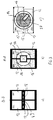
Figure 2 : shows two sectional views (a, b) of the material storage arrangement ofFig.1 , along lines B-B and A-A, respectively, and (c) a top view; -
Figure 3 : is an elevation view of the material storage arrangement ofFig.1 ; and -
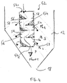
Figure 4 : is a sketch of one embodiment of a device for preventing free material fall. -
Figures 1 to 3 illustrate an embodiment of the presentmaterial storage arrangement 10 for storing, measuring and preparing charge material for a metallurgical furnace, and in particular for a blast furnace plant. - The blast furnace area with such material storage arrangement is generally referred to as stockhouse; the terms "stockhouse" and "material storage arrangement" will therefore be used hereinafter indifferently.
- The
stockhouse 10 comprises a set ofstorage bins 12 that are arranged in a side-by-side manner to be filled by amaterial feeding device 14 associated therewith. Thestorage bins 12 have a general hopper-like form converging toward the lower ends thereof. The storage bins are closed at their top by acover 15, in which afeeding opening 16 is arranged; and have anarrower outlet 18 at their lower end. In this embodiment, each bin 12 has twooutlets 18. Anextraction material gate 20 is generally associated with eachoutlet 18 to be able to close therespective outlet 18, or open it to allow material to flow down. Theextraction material gate 20 may e.g. include a pair of cylindrical registers cooperating to define a flow opening of desired cross-section; other types of gate members may however be used. - The
material feeding device 14 is positioned above thebins 12 in such a way as to be able to selectively fill each of thestorage bins 12 with granular material. Raw material (the term "raw" is used herein to refer to the granular material before the screening in the material feeding device 14) is conveyed to thematerial feeding device 14 by a rawmaterial feed system 22 that may be designed in any appropriate way. Here, the rawmaterial feed system 22 comprises abelt conveyor 24 that allows bringing the raw materials above thematerial feeding device 14. A guide arrangement is provided to guide the granular material from the end of thebelt conveyor 24 to thematerial feeding device 14, the granular material gravitally falling into the guide arrangement. More specifically, the guide arrangement comprises acollecting box 26 at the end ofconveyor 24, which collects the material falling from the conveyor and introduces it in arotating feeding chute 27. - In the embodiment, one
material feeding device 14 is associated with a pair ofstorage bins 12. Theoutlets 18 of thestorage bins 12 being aligned along oneconveyor line 30 of a BF charge conveying system (seeFig.3 a) . - Two weighing
hoppers 32 are arranged downstream of eachstorage bin 12, to receive and measure granular material from thestorage bin 12 when thematerial gate 20 is open. Each weighinghopper 32 comprises an outlet associated with a feeding gate 34 (e.g. cylindrical registers or the like). The feedinggate 34 is above theconveyor line 30 and aligned therewith, so that, when open, measured amounts of material are discharged onto theconveyor line 30. - The general structure of the conveyors, bins, weighing hoppers and gates are well-known to those skilled in the art and will therefore not be described in detail.
- It shall be appreciated that the
material feeding device 14 is configured to screen raw granular material arriving from the rawmaterial feed system 22 such that only material with desired granulometry is forwarded to the respective bin(s) 12. - The
material feeding device 14, centrally positioned above thebins 12, comprises arotatable platform 38, e.g. of circular shape, that supports ascreen unit 40 with vibrator. Theplatform 38 is supported in rotation on a circular runway (or alternatively on a central shaft) and can be selectively rotated by means of an electric motor and coupling gearing (not shown). In use, the platform is rotated depening on thebin 12 to be filled, in order to bring thescreen unit 40 in alignment with the desiredopening 16. - The
screen unit 40 comprises aninlet area 42, in which material falls from the open end ofchute 27. Thescreen unit 40 comprises a screening deck with one or more screens having a mesh size selected to be able to separate materials having a granulometry (grain size) above and below a desired size. - The screen of the
screen unit 40 is thus vibrated, which allows screening and sizing the raw material into: - oversized material, i.e. material of interest having a grain size superior to the mesh size of the screen; and
- undersized material, i.e. material having a grain size inferior to the screen mesh size and falling therethough.
- The oversized material exits the
screen unit 40 in the forward region thereof, through a dischargingspout 41, and is expelled towards the selectedbin 12, i.e. here in a generally radial direction having regard to therotating platform 38. As thescreen unit 40 is pivoted to be radially aligned with a respective feeding opening 16 in the top of thebin 12, the material expelled through the dischargingspout 41 falls into thisfeeding opening 16. - The undersized material, i.e. fines, is evacuated under the
screen unit 40. A vibratingchute 44 is located below the screening deck of thescreen unit 40, hence receiving the fines traversing the screen. In order to collect the fines separated in thescreen unit 40, anopening 46 is provided in therotary platform 38 at the location of the vibratingchute 44 and acollector bin 48 or chute is arranged below therotary platform 38. Thiscollector bin 48 also has a downwardly converging shape and is arranged between the neighbouringstorage bins 12. The fine grained material collected inbin 48 falls on anauxiliary fines conveyor 50 through abin outlet 49. - As it will be understood, the stockhouse
material storage arrangement 10 provides an improved design, where screened and sized granular material is stored instorage bins 12. This approach contrasts with the conventional stockhouse arrangement where the raw material is stored in the bins without pre-treatment/screening, and a vibro-screen is arranged below each bin. - The invention provides a number of benefits:
- the storage of sized material inside the bins reduces material segregation issues;
- the stockhouse construction is simplified, since only one vibrating screen unit is required for a set of bins, instead of one per bin;
- the measuring is also conveniently carried out since the stored material is ready for measuring;
- fines are eliminated at a single location, directly at the top of the installation.
- the handling of granular material is rationalised.
- The internal storage area of the
bins 12 is advantageously configured to prevent the free fall of material. This means that the bins are provided with internal guide elements, i.e. inside each bin, that provide a guide path for the granular material designed to slow the fall velocity, and leading them from the upper region of the bin to a median and/or lower region. Such a guide element, designated 52, may e.g. take the form of a chute, ladder or stairway, inclined or vertical, arranged in the bin to guide material entering the bin through its top opening towards the side walls in the median region of the bin. - Preferably, the
guide element 52 may be designed as a verticalrock ladder chute 52 as illustrated onFig.4 . Therock ladder 52 is a modular pipe with vertical and lateral openings, by which material is discharged depending on the level of already piled material. The rock ladder comprises a vertical tube 54 having a top inlet opening 541 and a bottom outlet opening 542. A number of ledges (or shelfs) 56 are installed at various levels, to form a series of stone boxes. Hence, the fall velocity of material entering therock ladder 52 is slowed down by cascading back and forth between theledges 56.Lateral openings 58 are provided at each level to feed up the bin in layers. - This rock ladder design is only one example of device for preventing free material fall and should not be regarded as limiting in any manner. Those skilled in the art may devise other kinds of devices for preventing free material fall.
- The weighing
hoppers 32 are also advantageously designed to avoid material degradation.
For example, diverter bars 60 may be arranged inside each weighinghopper 32, to create different flow channels avoiding the rat hole effect, which in conventional installations amplify the segregation on the main charging. During the filling of the weighinghopper 32, the diverter bars also avoid the free fall of the material -reducing the possible material degradation- and limit the centrifugal force on the grains which is the cause of the segregation. - As can be seen from
Figs.1 and2 , diverter bars 60 are straight bars of square, round or shaped cross-section, distributed at a plurality of levels over the height of the weighinghopper 32, the diverter bars of two consecutive levels being arranged in a staggered manner. - It remains to be noted that although the present embodiment has been described for the sake of exemplification with a pair of bins, one
material feeding device 14 can be centrally arranged with more bins, in particular 4 or 6. For exemple, referring toFig.3 a) , it can readily be seen that thematerial feeding device 14 could be installed for feeding 4 bins.
Claims (14)
- A material storage arrangement for a metallurgical furnace comprising:a set of storage bins (12) for granular material;a material feeding device (14) associated with said set of storage bins (12),the material feeding device (14) being arranged above said set of storage bins (12) and allowing to selectively fill each of the storage bins with granular material;a raw material feed system (22) to convey raw granular material to the material feeding device (14);a respective weighing hopper (32) arranged downstream of each storage bin (12) and comprising an outlet associated with a feeding gate (34);a charge conveying system (30) for collecting and conveying material selectively discharged from the weighing hoppers through their respective feeding gates;characterized in that said material feeding device (14) is configured to screen raw granular material arriving from said raw material feed system such that only material with desired granulometry is forwarded to the respective bin(s).
- The material storage arrangement according to claim 1, comprising a fines collecting bin (48) associated with said material feeding device (14) to collect undersized material screened out by the material feeding device before forwarding the material with desired size to the respective bin (12).
- The material storage arrangement according to claim 1 or 2, wherein said material feeding device (14) comprises a screen unit (40) receiving granular material from the raw material feed system (22), said screen unit comprising one or more screens of predetermined mesh size and being configured to filter out undersized granular material and forward oversized, desired material to the respective storage bins.
- The material storage arrangement according to claim 3, wherein said screen unit comprises a vibrator associated with the one or more screens.
- The material storage arrangement according to claim 2, 3 or 4, wherein said material feeding device (14) is generally centrally located with respect to said set of bins (12), with said fines collecting bin (48).
- The material storage arrangement according to claim 3, 4 or 5, wherein said material feeding device (14) comprises a rotatable platform (28) arranged above the set of storage bins (12), on which said screen unit (40) is supported.
- The material storage arrangement according to claim 6, wherein said fines collecting bin (48) is arranged below said rotatable platform (28), to collect fines falling from below said screen unit (40).
- The material storage arrangement according to any one of the preceding claims, wherein each storage bin (12) has its internal storage area configured to prevent free material fall.
- The material storage arrangement according to any one of the preceding claims, wherein each storage bin (12) comprises one or more material guide elements forming paths for material from the bin's top region to a lower region, said path(s) being designed to reduce the velocity of the falling material.
- The material storage arrangement according to claim 9, wherein the material guide elements may comprise a vertical or inclined chute, ladder or stairway, in particular a vertical rock ladder (52).
- The material storage arrangement according to any one of the preceding claims, wherein said weighing hoppers (32) include diverter bars to avoid degradation and control segregation of materials inside said weighing hoppers.
- The material storage arrangement according to any one of the preceding claims, wherein each storage bin (12) has its outlet (18) associated with a material gate (20).
- The material storage arrangement according to claim 7, wherein said fines collecting bin (48) has an outlet (49) opening onto a fines conveyor (50).
- A blast furnace plant comprising a material storage arrangement (10) according to any one of the preceding claims.
Priority Applications (10)
| Application Number | Priority Date | Filing Date | Title |
|---|---|---|---|
| EP15202150.7A EP3184947A1 (en) | 2015-12-22 | 2015-12-22 | Blast furnace stockhouse material storage arrangement |
| EP16826327.5A EP3394540B1 (en) | 2015-12-22 | 2016-12-21 | Blast furnace stockhouse arrangement |
| UAA201807905A UA121917C2 (en) | 2015-12-22 | 2016-12-21 | Blast furnace stockhouse arrangement |
| EA201891436A EA036293B1 (en) | 2015-12-22 | 2016-12-21 | Blast furnace stockhouse arrangement |
| JP2018530848A JP6557787B2 (en) | 2015-12-22 | 2016-12-21 | Stock house equipment for blast furnaces |
| KR1020187019364A KR102001401B1 (en) | 2015-12-22 | 2016-12-21 | Arrangement of furnace storage |
| CN201680074075.1A CN108700376B (en) | 2015-12-22 | 2016-12-21 | Blast furnace storage room device |
| US16/065,398 US11142803B2 (en) | 2015-12-22 | 2016-12-21 | Blast furnace stockhouse arrangement |
| BR112018012675-6A BR112018012675B1 (en) | 2015-12-22 | 2016-12-21 | LAYOUT OF WAREHOUSE AND BLAST FURNACE PLANT |
| PCT/EP2016/082250 WO2017108998A1 (en) | 2015-12-22 | 2016-12-21 | Blast furnace stockhouse arrangement |
Applications Claiming Priority (1)
| Application Number | Priority Date | Filing Date | Title |
|---|---|---|---|
| EP15202150.7A EP3184947A1 (en) | 2015-12-22 | 2015-12-22 | Blast furnace stockhouse material storage arrangement |
Publications (1)
| Publication Number | Publication Date |
|---|---|
| EP3184947A1 true EP3184947A1 (en) | 2017-06-28 |
Family
ID=55177709
Family Applications (2)
| Application Number | Title | Priority Date | Filing Date |
|---|---|---|---|
| EP15202150.7A Withdrawn EP3184947A1 (en) | 2015-12-22 | 2015-12-22 | Blast furnace stockhouse material storage arrangement |
| EP16826327.5A Active EP3394540B1 (en) | 2015-12-22 | 2016-12-21 | Blast furnace stockhouse arrangement |
Family Applications After (1)
| Application Number | Title | Priority Date | Filing Date |
|---|---|---|---|
| EP16826327.5A Active EP3394540B1 (en) | 2015-12-22 | 2016-12-21 | Blast furnace stockhouse arrangement |
Country Status (9)
| Country | Link |
|---|---|
| US (1) | US11142803B2 (en) |
| EP (2) | EP3184947A1 (en) |
| JP (1) | JP6557787B2 (en) |
| KR (1) | KR102001401B1 (en) |
| CN (1) | CN108700376B (en) |
| BR (1) | BR112018012675B1 (en) |
| EA (1) | EA036293B1 (en) |
| UA (1) | UA121917C2 (en) |
| WO (1) | WO2017108998A1 (en) |
Families Citing this family (5)
| Publication number | Priority date | Publication date | Assignee | Title |
|---|---|---|---|---|
| CN108100689A (en) * | 2018-02-02 | 2018-06-01 | 四川峨胜水泥集团股份有限公司 | Material distribution Input System |
| CN109357537B (en) * | 2018-11-01 | 2020-03-17 | 南京工程学院 | Cupola furnace with uniform distribution |
| CN109686220B (en) * | 2019-02-11 | 2021-04-13 | 内蒙古科技大学 | An experimental device for simulating the dynamic change of the material level during the descending process of the blast furnace throat material |
| BR102021000742A2 (en) * | 2021-01-15 | 2022-07-26 | Tecnored Desenvolvimento Tecnologico S.A. | LOAD DISTRIBUTION SYSTEM AND METHOD IN A METALLURGICAL FURNACE |
| CN113758277A (en) * | 2021-08-27 | 2021-12-07 | 广西柳钢新材料科技有限公司 | Double-chamber kiln charging method |
Citations (3)
| Publication number | Priority date | Publication date | Assignee | Title |
|---|---|---|---|---|
| JP2004010980A (en) * | 2002-06-07 | 2004-01-15 | Sumitomo Metal Ind Ltd | Operating method of blast furnace and bellless charging device |
| WO2010086379A1 (en) * | 2009-01-28 | 2010-08-05 | Paul Wurth S.A. | Computer system and method for controlling charging of a blast furnace by means of a user interface |
| JP2014162989A (en) * | 2013-02-28 | 2014-09-08 | Jfe Steel Corp | Raw material charging apparatus and method of charging raw material into blast furnace using the same |
Family Cites Families (8)
| Publication number | Priority date | Publication date | Assignee | Title |
|---|---|---|---|---|
| JPS5887856U (en) | 1981-12-09 | 1983-06-14 | 住友金属工業株式会社 | Raw material charging device |
| JPS61149409A (en) | 1984-12-24 | 1986-07-08 | Nippon Kokan Kk <Nkk> | Device for controlling grain size distribution of raw material |
| KR20000012233U (en) * | 1998-12-16 | 2000-07-05 | 이구택 | Ferroalloy Screening Feeder |
| KR100405519B1 (en) * | 1999-12-29 | 2003-11-14 | 주식회사 포스코 | Emergency measure method of ore large measure |
| JP2004346414A (en) * | 2003-05-26 | 2004-12-09 | Sumitomo Metal Ind Ltd | Blast furnace charging equipment |
| KR101290473B1 (en) * | 2011-09-28 | 2013-07-26 | 현대제철 주식회사 | apparatus for prevention of breaking sintered ore of sintered ore storing bin |
| KR101387341B1 (en) | 2012-12-27 | 2014-04-21 | (주)포스코 | System for supplying fuel or raw material using rotating chute in blast furnace and method thereof |
| JP6331607B2 (en) * | 2014-04-04 | 2018-05-30 | 新日鐵住金株式会社 | How to charge the bellless blast furnace |
-
2015
- 2015-12-22 EP EP15202150.7A patent/EP3184947A1/en not_active Withdrawn
-
2016
- 2016-12-21 EA EA201891436A patent/EA036293B1/en not_active IP Right Cessation
- 2016-12-21 UA UAA201807905A patent/UA121917C2/en unknown
- 2016-12-21 BR BR112018012675-6A patent/BR112018012675B1/en active IP Right Grant
- 2016-12-21 KR KR1020187019364A patent/KR102001401B1/en not_active Expired - Fee Related
- 2016-12-21 CN CN201680074075.1A patent/CN108700376B/en active Active
- 2016-12-21 US US16/065,398 patent/US11142803B2/en not_active Expired - Fee Related
- 2016-12-21 EP EP16826327.5A patent/EP3394540B1/en active Active
- 2016-12-21 WO PCT/EP2016/082250 patent/WO2017108998A1/en not_active Ceased
- 2016-12-21 JP JP2018530848A patent/JP6557787B2/en not_active Expired - Fee Related
Patent Citations (3)
| Publication number | Priority date | Publication date | Assignee | Title |
|---|---|---|---|---|
| JP2004010980A (en) * | 2002-06-07 | 2004-01-15 | Sumitomo Metal Ind Ltd | Operating method of blast furnace and bellless charging device |
| WO2010086379A1 (en) * | 2009-01-28 | 2010-08-05 | Paul Wurth S.A. | Computer system and method for controlling charging of a blast furnace by means of a user interface |
| JP2014162989A (en) * | 2013-02-28 | 2014-09-08 | Jfe Steel Corp | Raw material charging apparatus and method of charging raw material into blast furnace using the same |
Also Published As
| Publication number | Publication date |
|---|---|
| CN108700376A (en) | 2018-10-23 |
| US11142803B2 (en) | 2021-10-12 |
| EA201891436A1 (en) | 2019-01-31 |
| BR112018012675B1 (en) | 2021-12-28 |
| BR112018012675A2 (en) | 2018-12-04 |
| KR20180082621A (en) | 2018-07-18 |
| KR102001401B1 (en) | 2019-07-18 |
| CN108700376B (en) | 2020-07-28 |
| EA036293B1 (en) | 2020-10-22 |
| EP3394540B1 (en) | 2019-07-31 |
| WO2017108998A1 (en) | 2017-06-29 |
| JP6557787B2 (en) | 2019-08-07 |
| US20180371559A1 (en) | 2018-12-27 |
| EP3394540A1 (en) | 2018-10-31 |
| UA121917C2 (en) | 2020-08-10 |
| JP2019505661A (en) | 2019-02-28 |
Similar Documents
| Publication | Publication Date | Title |
|---|---|---|
| EP3394540B1 (en) | Blast furnace stockhouse arrangement | |
| KR101734470B1 (en) | System for crushing and selecting macadam automatically of stoney mountain | |
| KR101482475B1 (en) | Mobile discharge device for powder and granular material storage silo and powder and granular material storage silo | |
| CN101193810A (en) | Breakline chute for conveying materials | |
| US20050279868A1 (en) | Apparatus and process for control of rotary breakers | |
| CS248703B2 (en) | Apparatus for charging of the loose material with sintering tendency | |
| CN110626814B (en) | Tailing processing system | |
| CN106422956A (en) | Tube chain type loading homogenizing system | |
| NO140263B (en) | PROCEDURE AND DEVICE FOR CONTINUOUS MIXING AND REMOVAL OF POWDER OR PIECE MATERIAL FROM A CYLINDRICAL CONTAINER | |
| CN215905258U (en) | Multi-path material distributing device capable of adjusting discharge amount | |
| CN218475226U (en) | Full-automatic batching system | |
| CN106364930A (en) | Dispensing equipment | |
| CN206794089U (en) | A kind of new grinding ball separator | |
| TW201527014A (en) | Sinterstrand-charging device | |
| KR101037752B1 (en) | Method and equipment for loading in hopper | |
| CN113526039A (en) | Multi-path material distributing device capable of adjusting discharge amount | |
| CN206901349U (en) | A kind of rice enters more storehouse conveying devices | |
| CN206427541U (en) | Central feeding bucket | |
| JP6399265B1 (en) | Conveyor system | |
| CN204489987U (en) | The online sub-material process system of a kind of belt feeder | |
| CN116713075B (en) | A metallurgical slag grinding system and process | |
| CN220683691U (en) | Bucket elevator with breakage-proof function | |
| JP6095509B2 (en) | Weighing device | |
| SU1113204A1 (en) | Complex mechanized line for preparing moulding sands | |
| US1189748A (en) | Centrifugal dividing mechanism. |
Legal Events
| Date | Code | Title | Description |
|---|---|---|---|
| PUAI | Public reference made under article 153(3) epc to a published international application that has entered the european phase |
Free format text: ORIGINAL CODE: 0009012 |
|
| AK | Designated contracting states |
Kind code of ref document: A1 Designated state(s): AL AT BE BG CH CY CZ DE DK EE ES FI FR GB GR HR HU IE IS IT LI LT LU LV MC MK MT NL NO PL PT RO RS SE SI SK SM TR |
|
| AX | Request for extension of the european patent |
Extension state: BA ME |
|
| STAA | Information on the status of an ep patent application or granted ep patent |
Free format text: STATUS: THE APPLICATION IS DEEMED TO BE WITHDRAWN |
|
| 18D | Application deemed to be withdrawn |
Effective date: 20180102 |