EP3184759A1 - Compression device - Google Patents
Compression device Download PDFInfo
- Publication number
- EP3184759A1 EP3184759A1 EP15833111.6A EP15833111A EP3184759A1 EP 3184759 A1 EP3184759 A1 EP 3184759A1 EP 15833111 A EP15833111 A EP 15833111A EP 3184759 A1 EP3184759 A1 EP 3184759A1
- Authority
- EP
- European Patent Office
- Prior art keywords
- compressor
- heat exchanger
- working medium
- compression device
- port
- Prior art date
- Legal status (The legal status is an assumption and is not a legal conclusion. Google has not performed a legal analysis and makes no representation as to the accuracy of the status listed.)
- Withdrawn
Links
- 230000006835 compression Effects 0.000 title claims abstract description 99
- 238000007906 compression Methods 0.000 title claims abstract description 99
- 238000011084 recovery Methods 0.000 claims abstract description 83
- 239000007788 liquid Substances 0.000 claims description 18
- 230000005484 gravity Effects 0.000 claims description 16
- 230000007547 defect Effects 0.000 claims description 7
- 238000010438 heat treatment Methods 0.000 claims description 5
- 238000005086 pumping Methods 0.000 claims description 4
- 239000007791 liquid phase Substances 0.000 description 15
- 238000004891 communication Methods 0.000 description 4
- 230000001050 lubricating effect Effects 0.000 description 4
- 230000005540 biological transmission Effects 0.000 description 3
- 239000012809 cooling fluid Substances 0.000 description 3
- 238000012423 maintenance Methods 0.000 description 3
- 238000000034 method Methods 0.000 description 3
- 238000010248 power generation Methods 0.000 description 3
- 239000012530 fluid Substances 0.000 description 2
- 238000007689 inspection Methods 0.000 description 2
- 239000012071 phase Substances 0.000 description 2
- 229910000831 Steel Inorganic materials 0.000 description 1
- 229910002056 binary alloy Inorganic materials 0.000 description 1
- 238000009835 boiling Methods 0.000 description 1
- 238000001816 cooling Methods 0.000 description 1
- 239000000498 cooling water Substances 0.000 description 1
- 238000007599 discharging Methods 0.000 description 1
- 239000004519 grease Substances 0.000 description 1
- 230000002452 interceptive effect Effects 0.000 description 1
- MSSNHSVIGIHOJA-UHFFFAOYSA-N pentafluoropropane Chemical compound FC(F)CC(F)(F)F MSSNHSVIGIHOJA-UHFFFAOYSA-N 0.000 description 1
- 230000001172 regenerating effect Effects 0.000 description 1
- 239000010959 steel Substances 0.000 description 1
- 238000011144 upstream manufacturing Methods 0.000 description 1
- XLYOFNOQVPJJNP-UHFFFAOYSA-N water Substances O XLYOFNOQVPJJNP-UHFFFAOYSA-N 0.000 description 1
Images




Classifications
-
- F—MECHANICAL ENGINEERING; LIGHTING; HEATING; WEAPONS; BLASTING
- F01—MACHINES OR ENGINES IN GENERAL; ENGINE PLANTS IN GENERAL; STEAM ENGINES
- F01C—ROTARY-PISTON OR OSCILLATING-PISTON MACHINES OR ENGINES
- F01C1/00—Rotary-piston machines or engines
-
- F—MECHANICAL ENGINEERING; LIGHTING; HEATING; WEAPONS; BLASTING
- F25—REFRIGERATION OR COOLING; COMBINED HEATING AND REFRIGERATION SYSTEMS; HEAT PUMP SYSTEMS; MANUFACTURE OR STORAGE OF ICE; LIQUEFACTION SOLIDIFICATION OF GASES
- F25B—REFRIGERATION MACHINES, PLANTS OR SYSTEMS; COMBINED HEATING AND REFRIGERATION SYSTEMS; HEAT PUMP SYSTEMS
- F25B11/00—Compression machines, plants or systems, using turbines, e.g. gas turbines
- F25B11/02—Compression machines, plants or systems, using turbines, e.g. gas turbines as expanders
-
- F—MECHANICAL ENGINEERING; LIGHTING; HEATING; WEAPONS; BLASTING
- F01—MACHINES OR ENGINES IN GENERAL; ENGINE PLANTS IN GENERAL; STEAM ENGINES
- F01K—STEAM ENGINE PLANTS; STEAM ACCUMULATORS; ENGINE PLANTS NOT OTHERWISE PROVIDED FOR; ENGINES USING SPECIAL WORKING FLUIDS OR CYCLES
- F01K23/00—Plants characterised by more than one engine delivering power external to the plant, the engines being driven by different fluids
- F01K23/02—Plants characterised by more than one engine delivering power external to the plant, the engines being driven by different fluids the engine cycles being thermally coupled
- F01K23/06—Plants characterised by more than one engine delivering power external to the plant, the engines being driven by different fluids the engine cycles being thermally coupled combustion heat from one cycle heating the fluid in another cycle
- F01K23/08—Plants characterised by more than one engine delivering power external to the plant, the engines being driven by different fluids the engine cycles being thermally coupled combustion heat from one cycle heating the fluid in another cycle with working fluid of one cycle heating the fluid in another cycle
-
- F—MECHANICAL ENGINEERING; LIGHTING; HEATING; WEAPONS; BLASTING
- F01—MACHINES OR ENGINES IN GENERAL; ENGINE PLANTS IN GENERAL; STEAM ENGINES
- F01K—STEAM ENGINE PLANTS; STEAM ACCUMULATORS; ENGINE PLANTS NOT OTHERWISE PROVIDED FOR; ENGINES USING SPECIAL WORKING FLUIDS OR CYCLES
- F01K27/00—Plants for converting heat or fluid energy into mechanical energy, not otherwise provided for
- F01K27/02—Plants modified to use their waste heat, other than that of exhaust, e.g. engine-friction heat
-
- F—MECHANICAL ENGINEERING; LIGHTING; HEATING; WEAPONS; BLASTING
- F25—REFRIGERATION OR COOLING; COMBINED HEATING AND REFRIGERATION SYSTEMS; HEAT PUMP SYSTEMS; MANUFACTURE OR STORAGE OF ICE; LIQUEFACTION SOLIDIFICATION OF GASES
- F25B—REFRIGERATION MACHINES, PLANTS OR SYSTEMS; COMBINED HEATING AND REFRIGERATION SYSTEMS; HEAT PUMP SYSTEMS
- F25B25/00—Machines, plants or systems, using a combination of modes of operation covered by two or more of the groups F25B1/00 - F25B23/00
- F25B25/005—Machines, plants or systems, using a combination of modes of operation covered by two or more of the groups F25B1/00 - F25B23/00 using primary and secondary systems
-
- F—MECHANICAL ENGINEERING; LIGHTING; HEATING; WEAPONS; BLASTING
- F25—REFRIGERATION OR COOLING; COMBINED HEATING AND REFRIGERATION SYSTEMS; HEAT PUMP SYSTEMS; MANUFACTURE OR STORAGE OF ICE; LIQUEFACTION SOLIDIFICATION OF GASES
- F25B—REFRIGERATION MACHINES, PLANTS OR SYSTEMS; COMBINED HEATING AND REFRIGERATION SYSTEMS; HEAT PUMP SYSTEMS
- F25B2500/00—Problems to be solved
- F25B2500/01—Geometry problems, e.g. for reducing size
-
- F—MECHANICAL ENGINEERING; LIGHTING; HEATING; WEAPONS; BLASTING
- F25—REFRIGERATION OR COOLING; COMBINED HEATING AND REFRIGERATION SYSTEMS; HEAT PUMP SYSTEMS; MANUFACTURE OR STORAGE OF ICE; LIQUEFACTION SOLIDIFICATION OF GASES
- F25B—REFRIGERATION MACHINES, PLANTS OR SYSTEMS; COMBINED HEATING AND REFRIGERATION SYSTEMS; HEAT PUMP SYSTEMS
- F25B9/00—Compression machines, plants or systems, in which the refrigerant is air or other gas of low boiling point
- F25B9/06—Compression machines, plants or systems, in which the refrigerant is air or other gas of low boiling point using expanders
Definitions
- the present invention relates to a compression device.
- Patent Document 1 discloses an energy recovery system of a compression device including: a compressor; an evaporator for conducting heat exchange between compressed gas that has been discharged from the compressor and a liquid-phase working medium; a cooler for cooling the gas that has flowed out from the evaporator; a turbine in which the gas-phase working medium that has flowed out from the evaporator flows; an AC generator connected to the turbine; a condenser for condensing the working medium that has flowed out from the turbine; and a circulating pump for pumping the liquid-phase working medium that has flowed out from the condenser, to the evaporator.
- energy included in the compressed gas is recovered in the evaporator and by using the energy, electric power generation is performed in the AC generator.
- Patent Document 1 JP 2013-057256 A
- An object of the present invention is to provide a compression device that can achieve an effective recovery of heat energy included in compressed gas and a reduction of a pressure loss of the compressed gas.
- a compression device includes: a compressor for compressing gas; and a heat energy recovery unit for recovering heat energy of the gas that has been compressed in the compressor and discharged therefrom, the heat energy recovery unit including: a heat exchanger having an inflow port for allowing inflow of the compressed gas, the heat exchanger for heating a working medium by heat of the compressed gas; an expansion device for expanding the working medium that has flowed out from the heat exchanger; a power recovery unit connected to the expansion device; a condenser for condensing the working medium that has flowed out from the expansion device; and a pump for pumping the working medium that has flowed out from the condenser, to the heat exchanger, wherein the heat exchanger is positioned closer to the compressor than the expansion device and is arranged so that the inflow port is oriented to face the compressor.
- a compression device according to an embodiment of the present invention will be described with reference to Fig. 1 to Fig. 3 .
- the compression device includes a compression device body 100 and a heat energy recovery unit 200.
- the compression device body 100 includes a first compressor 102 for compressing gas (for example, air), a first cooler 104, a second compressor 106 for further compressing the compressed gas that has flowed out from the first cooler 104, and a second cooler 108.
- gas for example, air
- first cooler 104 for compressing gas
- second compressor 106 for further compressing the compressed gas that has flowed out from the first cooler 104
- second cooler 108 for example, air
- the first compressor 102 is a screw compressor.
- the first compressor 102 includes a compressor body, a motor, and a power transmission device for transmitting power of the motor to the compressor body.
- the compressor body includes a screw rotor, a housing that houses the screw rotor, and a discharge section for discharging the compressed gas.
- the screw rotor is formed by a rotor shaft as a rotary shaft and a screw (compression member) that is rotatable along with the rotor shaft.
- the first compressor 102 is arranged so that the rotor shaft is horizontally oriented.
- the first compressor 102 is not limited to the screw compressor and may be a compressor that includes a rotary shaft for driving a compression member; in other words, the compressor may be a turbo compressor or a scroll compressor.
- the second compressor 106 is a screw compressor.
- the structure of the second compressor 106 being the same as that of the first compressor 102 includes a compressor body, a motor, and a power transmission device for transmitting power of the motor to the compressor body.
- a single motor and a single power transmission device may be used in common by the first compressor 102 and the second compressor 106.
- the second compressor 106 is arranged so that a rotor shaft of a screw rotor is horizontally oriented and so that the rotor shaft thereof is oriented parallel to the rotor shaft of the first compressor 102.
- the second compressor 106 is not limited to the screw compressor and may be a turbo compressor or a scroll compressor.
- the first cooler 104 is configured to cool the compressed gas that has been discharged from the first compressor 102 and subsequently passed through a first heat exchanger 202, which will be described below, but has not yet flowed in the second compressor 106.
- the second cooler 108 is configured to cool the compressed gas that has been discharged from the second compressor 106 and subsequently passed through a second heat exchanger 204, which will be described below, but has not yet been supplied to the outside.
- Flow passages of the compressed gas between the first cooler 104 and the second compressor 106 and between the second cooler 108 and the outside are not shown in Fig. 1 , and likewise, the flow passages are not shown in the following Fig. 4 and Fig. 6 .
- These coolers 104, 108 are arranged below the first compressor 102 and the second compressor 106, respectively.
- the compression device body 100 is arranged on a first base plate 130 of a substantially rectangular shape.
- the first cooler 104 and the second cooler 108 are directly placed on an upper surface of the first base plate 130
- the first compressor 102 and the second compressor 106 are arranged above the both coolers 104, 108; in other words, the compressors are positioned above and separated from the upper surface of the first base plate 130.
- the device is arranged on the first base plate 130.
- the same description applies to the aspect of a second base plate 230, which will be described below.
- the compression device body 100 is covered by a first cover 140 while being arranged on the first base plate 130.
- Fig. 1 shows a partially cut-away view of the first cover 140.
- the heat energy recovery unit 200 is a so-called binary system, which utilizes an Organic Rankine Cycle, and the unit includes the first heat exchanger 202, the second heat exchanger 204, an oil separator 206, an urgent shut-off valve 208, an expansion device 210, a generator 212 that is a power recovery unit 212 connected to the expansion device 210, a condenser 214, a receiver 216, a pump 222, and a circulating flow passage 224.
- the circulating flow passage 224 establishes a connection from the first heat exchanger 202 through the oil separator 206, the urgent shut-off valve 208, the expansion device 210, the condenser 214, and the receiver 216 to the pump 222 in the mentioned order and a connection from the second heat exchanger 204 through the oil separator 206, the urgent shut-off valve 208, the expansion device 210, the condenser 214, and the receiver 216 to the pump 222 in the mentioned order.
- a working medium organic fluid such as R245fa having a boiling point lower than that of water
- the circulating flow passage 224 includes a branch flow passage 226.
- the first heat exchanger 202 and the second heat exchanger 204 are arranged in parallel with each other.
- the first heat exchanger 202 includes an inflow port 202a for allowing inflow of the compressed gas that has been compressed in the first compressor 102.
- the working medium is heated by heat of the compressed gas that has flowed through the inflow port 202a into the first heat exchanger. In other words, the compressed gas is cooled by the working medium.
- the first heat exchanger 202 is a so-called finned tube heat exchanger. Note that a plate heat exchanger may be used as the first heat exchanger 202, and likewise, a plate heat exchanger may be used as the second heat exchanger 204.
- the second heat exchanger 204 includes an inflow port 204a for allowing inflow of the compressed gas that has been compressed in the second compressor 106.
- the working medium is heated by heat of the compressed gas that has flowed through this inflow port 204a into the second heat exchanger. In other words, the compressed gas is cooled by the working medium.
- the oil separator 206 provided downstream of the first heat exchanger 202 and the second heat exchanger 204 is configured to separate oil included in the working medium that has flowed out from the both heat exchangers 202, 204.
- the oil is used, for example, for lubricating various components of the expansion device 210 or the pump 222.
- the expansion device 210 is provided downstream of the oil separator 206.
- a volumetric screw expansion device is applied as the expansion device 210.
- This expansion device 210 includes: a casing that is internally provided with a rotor chamber; and a pair of male and female screw rotors that are rotatably supported in the rotor chamber. The gas-phase working medium that has flowed in the rotor chamber expands, thereby rotating the screw rotors.
- the expansion device 210 is not limited to the screw expansion device, and alternatively, a centrifugal expansion device or a scroll expansion device may be applied.
- the generator 212 is connected to the expansion device 210.
- This generator 212 includes a rotary shaft that is connected at least one of the pair of screw rotors of the expansion device 210.
- the rotary shaft rotates along with rotation of the screw rotor; thereby, the generator 212 generates electric power.
- the condenser 214 provided downstream of the expansion device 210 is configured to cool the working medium with cooling fluid (such as cooling water), which is to be supplied from the outside, thereby condensing the working medium (forming the working medium into liquid-phase).
- cooling fluid such as cooling water
- the receiver 216 provided downstream of the condenser 214 is configured to store the liquid-phase working medium that has flowed out from the condenser 214. As shown in Fig. 1 and Fig. 2 , the receiver 216 has a substantially H-shape in planar view. Specifically, the receiver 216 includes: a first tubular portion 218 and a second tubular portion 220 that are arranged in a horizontal surface; and a communication tubular portion 219 that allows communication between the first tubular portion 218 and the second tubular portion 220. Note that the communication tubular portion 219 is connected to respective axial ends of the both tubular portions 218, 220 and the receiver 216 may therefore be formed in a substantially U-shape in planar view.
- the first tubular portion 218 is provided with an inflow port 216a for allowing the liquid-phase working medium that has flowed out from the condenser 214, to flow in the first tubular portion 218.
- the first tubular portion 218 is provided with an outflow port 216b for allowing the liquid-phase working medium to flow out from the first tubular portion 218.
- the second tubular portion 220 is provided with a liquid level sensor 221 for detecting the liquid level of the working medium.
- the liquid level sensor 221 and the working medium inflow port 216a are separated from each other via the communication tubular portion 219.
- a detected value by the liquid level sensor 221 may be inhibited from changing due to fluctuations in a liquid surface within the first tubular portion 218, which are caused when the working medium has flowed through the inflow port 216a into the first tubular portion 218 to impact against the liquid surface.
- the pump 222 is provided downstream of the receiver 216 (at a location that is downstream of the receiver 216 in the circulating flow passage 224 and that is upstream of a connected portion of the circulating flow passage 224 with the branch flow passage 226).
- the pump 222 pressurizes the liquid-phase working medium to a predetermined pressure to send the working medium to the first heat exchanger 202 and the second heat exchanger 204.
- the pump 222 includes: a suction port 222a for allowing the liquid-phase working medium to flow in the pump; and an oil supply port 222b for allowing the oil to flow in the pump.
- An oil supply flow passage 223 (see Fig.
- a centrifugal pump provided with an impeller as a rotor, a gear pump including a rotor which is formed by a pair of gears, a screw pump, a trochoid pump, or the like is applied as the pump 222.
- the heat energy recovery unit 200 is arranged on the second base plate 230 of a rectangular shape.
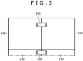
- Fig. 1 shows a state where the first base plate 130 and the second base plate 230 are separated from each other but as shown in Fig. 3 , these base plates are actually in contact with each other.
- the first heat exchanger 202 is arranged on one of two opposite corner portions of the second base plate 230, which are positioned so as to face the first base plate 130 (the first heat exchanger 202 is arranged on the upper right corner in Fig. 1 ).
- the first heat exchanger 202 is arranged so that the inflow port 202a is oriented to face a compressed gas discharge port 102a of the first compressor 102.
- the discharge port 102a of the first compressor 102 is an opening that is positioned at an end of a flow passage extending from a compression space, which accommodates the screw (compression member), to the downstream side.
- a discharge port 106a of the second compressor 106 has the opening similar to that of the discharge port 102a.
- a direction into which the inflow port 202a of the first heat exchanger 202 is opened (a direction that is perpendicular to a face including the opening) is substantially in parallel with a direction in which the rotor shaft of the first compressor 102 extends.
- the first heat exchanger 202 is arranged by using a mounting stand (not shown) so as to be positioned above and separated from an upper surface of the second base plate 230.
- the second heat exchanger 204 is arranged on the other one of the foregoing two opposite corner portions of the second base plate 230 (the second heat exchanger 204 is arranged on the lower right corner in Fig. 1 ).
- the second heat exchanger 204 is arranged so that the inflow port 204a is oriented to face the compressed gas discharge port 106a of the second compressor 106.
- a direction into which the inflow port 204a of the second heat exchanger 204 is opened (a direction that is perpendicular to a face including the opening) is substantially in parallel with a direction in which the rotor shaft of the second compressor 106 extends.
- the second heat exchanger 204 is arranged by using a mounting stand 205 so as to be positioned above and separated from the upper surface of the second base plate 230.
- the oil separator 206 is arranged between the foregoing two opposite corner portions of the second base plate 230. As shown in Fig. 2 , the oil separator 206 is arranged by using a mounting stand 207 so as to be positioned above and separated from the upper surface of the second base plate 230.
- the expansion device 210 is arranged on one of four corner portions of the second base plate 230, which is a different corner portion from the foregoing two opposite corner portions (the expansion device 210 is arranged on the lower left corner in Fig. 1 ). As shown in Fig. 2 , the expansion device 210 is arranged by using a mounting stand 213 so as to be positioned above and separated from the upper surface of the second base plate 230. The condenser 214 is arranged at a position adjacent to the expansion device 210.
- the receiver 216 is arranged below the condenser 214.
- the inflow port 216a of the receiver 216 is arranged below an outflow port 214b (opening for allowing the liquid-phase working medium to flow out) of the condenser 214 in the gravity direction.
- the working medium that has flowed out from the condenser 214 can be effectively stored in the receiver 216.
- the inflow port 216a of the receiver 216 is arranged below the outflow port 214b of the condenser 214 in the gravity direction, the inflow port 216a may be positioned so as to overlap the outflow port 214b in the gravity direction.
- the inflow port 216a may be positioned below the outflow port 214b and separated from the outflow port 214b in the horizontal direction so as not to overlap the outflow port 214b in the gravity direction.
- the receiver 216 is mounted on a support table 217, thereby being arranged to be positioned above and separated from the upper surface of the second base plate 230.
- the pump 222 is arranged at the lateral side of the receiver 216. As shown in Fig. 2 , the suction port 222a of the pump 222 is located on the same level as the outflow port 216b of the receiver 216 in the gravity direction. Accordingly, since the suction port 222a of the pump 222 is filled with the liquid-phase working medium, the inflow of gas into the pump 222 is inhibited. Furthermore, a portion of the receiver 216, which is located lower in the gravity direction than the suction port 222a of the pump 222 is reduced (it is difficult for the working medium to be suctioned from the portion by the pump 222); therefore, a total volume of the working medium to be stored in the receiver 216 can be reduced.
- the pump 222 is positioned above and separated from the second base plate 230 by using a mounting stand (not shown) and is arranged so that the oil supply port 222b is oriented downward, and the oil supply flow passage 223 is connected to the oil supply port 222b while being located below the pump 222.
- the heat energy recovery unit 200 is covered by a second cover 240, which is shown in Fig. 3 , while being arranged on the second base plate 230. Note that Fig. 1 shows a partially cut-away view of the second cover 240.
- the compression device is provided with a base plate fixing member 330 by which the first base plate 130 and the second base plate 230 are positionally fixed relative to each other.
- the base plate fixing member 330 includes a flat plated fixing panel and fixtures such as bolts, which enable the fixing panel to be fixed to the both base plates 130, 230.
- the first base plate 130 and the second base plate 230 are fixed in advance by the base plate fixing member 330; thereby, misalignment of the inflow port 202a of the heat exchanger 202 to the discharge port 102a of the compressor 102 and misalignment of the inflow port 204a of the heat exchanger 204 to the discharge port 106a of the compressors 106 are prevented.
- the first cover 140 and the second cover 240 are fixed by a cover fixing member 340 in a state where the first cover 140 and the second cover 240 are positionally fixed relative to each other.
- the cover fixing member 340 includes a flat plated fixing panel and fixtures such as bolts, which enable the fixing panel to be fixed to the both covers 140, 240.
- Flexible hoses 300 having flexibilities, respectively are utilized in at least a portion of a pipe connecting between the inflow port 202a of the first heat exchanger 202 and the discharge port 102a of the first compressor 102 and in at least a portion of a pipe connecting between an outflow port 202b of the first heat exchanger 202 and an inflow port 104a of the first cooler 104.
- the flexible hose 300 is deformable in a direction orthogonal to a longitudinal direction thereof.
- the flexible hoses 300 having flexibilities, respectively are utilized in at least a portion of a pipe connecting between the inflow port 204a of the second heat exchanger 204 and the discharge port 106a of the second compressor 106 and in at least a portion of a pipe connecting between an outflow port 204b of the second heat exchanger 204 and an inflow port 108a of the second cooler 108.
- gas is compressed in the first compressor 102.
- the temperature of the gas rises.
- This compressed gas flows from the discharge port 102a of the first compressor 102 through the flexible hose 300 and the inflow port 202a of the first heat exchanger 202 into the first heat exchanger 202.
- the compressed gas flows from the outflow port 202b of the first heat exchanger 202 through the flexible hose 300 and the inflow port 104a of the first cooler 104 into the first cooler 104.
- the compressed gas that has been cooled in the first cooler 104 is further compressed by the second compressor 106.
- the temperature of the gas rises.
- This compressed gas flows from the discharge port 106a of the second compressor 106 through the flexible hose 300 and the inflow port 204a of the second heat exchanger 204 into the second heat exchanger 204.
- the compressed gas flows from the outflow port 204b of the second heat exchanger 204 through the flexible hose 300 and the inflow port 108a of the second cooler 108 into the second cooler 108.
- the compressed gas that has been cooled in the second cooler 108 is supplied to the outside.
- the working medium that has evaporated due to the heat exchange with the compressed gas in the first heat exchanger 202 and the second heat exchanger 204 flows in the oil separator 206.
- the working medium that has flowed out from the oil separator 206 flows in the expansion device 210.
- the working medium is expanded and thereby the expansion device 210 is driven; therefore, electric power is generated in the generator 212.
- the generated electric power is supplied, for example, to a motor for driving the first compressor 102 and the second compressor 106, various control devices such as a controller in the compression device body 100 and electromagnetic valves, and a pump for supplying oil, for example, to gears.
- the generated electric power serves as regenerative electric power to be consumed in the compression device.
- the electric power may be partially utilized as power source for devices (for example, the pump 222 or the control devices) of the heat energy recovery unit 200 itself.
- the working medium that has flowed out from the expansion device 210 is condensed in the condenser 214, thereafter flowing in the receiver 216 that is located below the condenser 214.
- the liquid-phase working medium that has flowed out from the receiver 216 flows in the pump 222, thereafter being pumped out by the pump 222 therefrom through the circulating flow passage 224 and the branch flow passage 226 to the first heat exchanger 202 and the second heat exchanger 204.
- the working medium circulates through the circulating flow passage 224 and the branch flow passage 226; thereby, the electric power generation is continued in the generator 212 during the operation of the compression device body 100.
- the first heat exchanger 202 is positioned closer to the first compressor 102 than the expansion device 210; therefore, a distance from the first compressor 102 to the first heat exchanger 202 is reduced.
- the inflow port 202a of the first heat exchanger 202 is oriented to face the first compressor 102. Consequently, the pipe connecting the first compressor 102 to the first heat exchanger 202 is inhibited from being excessively curved and bent. Likewise, the pipe to the second heat exchanger 204 is inhibited from being curved and bent.
- an effective recovery of heat energy included in the compressed gas by using the heat energy recovery unit 200 and a reduction of a pressure loss generated in the compressed gas that has been discharged from each of the compression devices 102, 106 can be achieved.
- the first heat exchanger 202 is arranged on the forgoing opposite corner portion so that the direction into which the inflow port 202a is opened is oriented substantially in parallel with the rotor shaft of the first compressor 102. Therefore, the pipe connecting the first compressor 102 to the first heat exchanger 202 is further inhibited from being curved and bent. Consequently, a pressure loss generated in the compressed gas is further reduced. Likewise, a pressure loss of the compressed gas is reduced in the second heat exchanger 204.
- a compression device members of a compression device body and a heat energy recovery unit are densely arranged; therefore, the assembly operation may be complicated.
- the heat energy recovery unit 200 before being mounted to the compression device body, the heat energy recovery unit 200 can be mounted on the second base plate 230; in other words, the heat energy recovery unit 200 can be unitized to the compression device body.
- the assembly operation of the compression device can be easily conducted.
- the assembly operation of the compression device can be easily conducted.
- the heat energy recovery unit 200 is provided on the base plate that is different from the base plate on which the compression device body 100 is provided. Therefore, in a factory or the like, the compression device body 100 and the heat energy recovery unit 200 are not necessary manufactured integrally. Consequently, an operation for subsequently mounting the heat energy recovery unit 200 to the compression device body 100 that may be singly used is easily performed. In addition, in the case of mounting the heat energy recovery unit 200 to the compression device body 100, the first cover 140 and the second cover 240 can be easily fixed by using the cover fixing member 340.
- the expansion device 210 is arranged on the corner portion of the second base plate 230. Accordingly, for example, a window for working is provided in a lateral surface of the second cover 240, which enables an easy access from the outside of the second base plate 230 to the expansion device 210. Therefore, an operation, for example, for doing maintenance on the expansion device 210 can be easily conducted.
- the expansion device 210 is mounted on the mounting stand 213; thereby, the height of the expansion device 210 can be secured. As a result, the expansion device 210 can be easily hoisted with a crane and therefore an operation of carrying the expansion device 210 in or out of the heat energy recovery unit 200 is easily conducted.
- the pump 222 is positioned above and separated from the second base plate 230 and is arranged so that the oil supply port 222b is oriented downward, and the oil supply flow passage 223 is connected to the oil supply port 222b while being arranged below the pump 222. Therefore, the size of the heat energy recovery unit 200 can be reduced in the horizontal direction.
- the pipe connecting the compression device body 100 to the heat energy recovery unit 200 includes the flexible hose 300. Therefore, the misalignment of the inflow port 202a of the first heat exchanger 202 to the discharge port 102a of the first compressor 102 and the misalignment of the inflow port 204a of the second heat exchanger 204 to the discharge port 106a of the second compressors 106 are prevented, while these inflow ports 202a, 204a can be surely connected to the discharge ports 102a, 106a. Likewise, misalignment between the first heat exchanger 202 and the first cooler 104 and misalignment between the second heat exchanger 204 and the second cooler 108 are prevented, while secure connections are established.
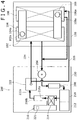
- Fig. 4 is a drawing showing another example of the compression device.
- the heat exchangers 202, 204 are not provided on the second base plate 230.
- a portion of the circulating flow passage 224, to which the first heat exchanger 202 is connected is connected to the first cooler 104, and a portion of the circulating flow passage 224, to which the second heat exchanger 204 is connected, is connected to the second cooler 108.
- the first and second coolers 104, 108 flow passages through which the working medium flows and flow passages through which cooling fluid (not shown) flows are formed, and therefore the compressed gas is cooled by the working medium and the cooling fluid.
- the coolers 104, 108 fill the roles of the heat exchangers 202, 204 of the heat energy recovery unit 200.
- the compressed gas inflow port 104a of the first cooler 104 is oriented so as to face the compressed gas discharge port 102a of the first compressor 102 in the gravity direction.
- the compressed gas inflow port 108a of the second cooler 108 is oriented so as to face the compressed gas discharge port 106a of the second compressor 106 in the gravity direction.
- Other configurations of the compression device are similar to those in Fig. 1 .
- the coolers 104, 108 are positioned closer to the first compressor 102 and the second compressor 106 than the expansion device 210, and the compressed gas inflow ports 104a, 108a of the coolers 104, 108 face the first and second compressors 102, 106, respectively; therefore, a pressure loss generated in the compressed gas can be reduced. Further, a heat exchange of the working medium with the compressed gas is made in the coolers 104, 108; in other words, the coolers 104, 108 fill the roles of the heat exchangers 202, 204 of the heat energy recovery unit 200. Therefore, the pressure loss of the compressed gas can be further reduced.
- Fig. 5 is a drawing showing still another example of the compression device.
- the first heat exchanger 202 and the second heat exchanger 204 are arranged in series with each other in the circulating flow passage 224, and the working medium that has flowed out from the first heat exchanger 202 flows in the second heat exchanger 204.
- the working medium that has been heated in the first heat exchanger 202 and the second heat exchanger 204 flows through the oil separator 206 and the urgent shut-off valve 208 into the expansion device 210, therefore driving the expansion device 210 and the generator 212.
- Other configurations of the compression device are similar to those in Fig. 1 . In the compression device shown in Fig.
- the working medium flowing in the first heat exchanger 202 is the same volume as in the second heat exchanger 204; therefore, an operation for adjusting the volume of distribution of the working medium to the first and second heat exchangers 202, 204 in a parallel structure will not be necessary.
- the coolers 104, 108 may be arranged in series with each other in the circulating flow passage 224.
- Fig. 6 is a drawing showing still another example of the compression device.
- the compression device body 100 includes a first bypass flow passage 81, a first valve member 82, a second bypass flow passage 83, and a second valve member 84 in a flow passage of the compressed gas.
- Other configurations are similar to those in Fig. 1 .
- the first bypass flow passage 81 connects a portion of the flow passage between the discharge port 102a of the first compressor 102 and the inflow port 202a of the first heat exchanger 202 to a portion of the flow passage between the outflow port 202b of the first heat exchanger 202 and the inflow port 104a of the first cooler 104.
- the first valve member 82 includes two valves 82a, 82b.
- the valve 82a is provided in the first bypass flow passage 81.
- the valve 82a is normally closed.
- the valve 82b is located downstream of the connected portion of the flow passage between the discharge port 102a of the first compressor 102 and the inflow port 202a of the first heat exchanger 202, with the first bypass flow passage 81.
- the valve 82b is normally open.
- the first valve member 82 allows the compressed gas to flow into the first heat exchanger 202 and restricts the compressed gas from flowing into the first bypass flow passage 81.
- the second bypass flow passage 83 connects a portion of the flow passage between the discharge port 106a of the second compressor 106 and the inflow port 204a of the second heat exchanger 204 to a portion of the flow passage between the outflow port 204b of the second heat exchanger 204 and the inflow port 108a of the second cooler 108.
- the second valve member 84 includes two valves 84a, 84b.
- the valve 84a is provided in the second bypass flow passage 83.
- the valve 84a is normally closed.
- the valve 84b is located downstream of the connected portion of the flow passage between the discharge port 106a of the second compressor 106 and the inflow port 204a of the second heat exchanger 204, with the second bypass flow passage 83.
- the valve 84b is normally open.
- the second valve member 84 allows the compressed gas to flow into the second heat exchanger 204 and restricts the compressed gas from flowing into the second bypass flow passage 83.
- the first valve member 82 is switched; thereby, the compressed gas that has been discharged from the first compressor 102 is restricted from flowing in the first heat exchanger 202 and the compressed gas flows through the first bypass flow passage 81 into the first cooler 104 that is located downstream of the first heat exchanger 202.
- the second valve member 84 is switched; thereby, the compressed gas that has been discharged from the second compressor 106 is restricted from flowing in the second heat exchanger 204 and the compressed gas flows through the second bypass flow passage 83 into the second cooler 108 that is located downstream of the second heat exchanger 204.
- the supply of the compressed gas to the first heat exchanger 202 and the second heat exchanger 204 is stopped and thereby the electric power generation is stopped.
- whether or not there has been a defect in the heat energy recovery unit 200 is determined by at least one of the pressure or temperature of the working medium flowing in the expansion device 210, the number of rotations of the expansion device 210 or the generator 212, the frequency of electric power output from the generator 212, and the internal temperature of the generator 212. Further, in a case where the liquid level inside the receiver 216 has reached a value below a predetermined value, a case where a signal indicating a failure of an electronic device, for example, an inverter or a converter which is associated with the generator 212 has been detected in a control unit of the compression device, and a case where an emergency stop has been commanded by an operator, a determination of the occurrence of the defect is made.
- the first and second bypass flow passages 81, 83 are provided; thereby, when there has been a defect in the heat energy recovery unit 200, the heat energy recovery unit 200 can be promptly stopped and an inspection or the like of the compression device can be conducted. In addition, even in a state where the operation of the heat energy recovery unit 200 is stopped, the compression device body 100 can continue to be driven.
- Fig. 7 is a drawing showing another example of the heat energy recovery unit 200.
- the expansion device 210 and the generator 212 are arranged in the substantially center in the width direction of the second base plate 230 (in the up to down direction in Fig. 7 ).
- the width direction is a direction that is perpendicular to the direction in which the heat energy recovery unit 200 and the compression device body 100 of Fig. 1 are arranged in the horizontal surface.
- the condenser 214 and the receiver 216, and the pump 222 are arranged on the respective sides of the expansion device 210 and the generator 212 as viewed in the width direction.
- Other configurations are similar to those in Fig. 1 .
- the expansion device 210 is arranged on the mounting stand 213 in the same way as in Fig. 2 .
- the height of the expansion device 210 can be secured, and the expansion device 210 can be easily hoisted with a crane and therefore the expansion device 210 can be easily carried in and out of the heat energy recovery unit 200.
- Fig. 8 is a drawing showing another example of the receiver 216.
- the working medium outflow port 216b is provided in the second tubular portion 220.
- the liquid level sensor 221 is provided on the opposite side of the outflow port 216b of the second tubular portion 220. Even in this case, a detected value by the liquid level sensor 221 may be inhibited from changing due to fluctuations in the liquid surface, which are caused by the inflow of the working medium into the first tubular portion 218.
- the tubular portions 218, 220 of the receiver 216 are oriented in parallel with each other in the horizontal surface; however, the orientation of the receiver 216 is not limited thereto.
- the receiver 216 may be arranged so that the first tubular portion 218 and the second tubular portion 220 are aligned in the up to down direction along a surface that is perpendicular to the horizontal surface.
- the inflow port 216a is provided in an upper portion of the first tubular portion 218 and the outflow port 216b is provided in a lower portion of the second tubular portion 220.
- the fluid level sensor 221 is provided within the second tubular portion 220.
- the liquid-phase working medium is stored in the second tubular portion 220 located at the lower side, and in addition, the second tubular portion 220 is provided with the outflow port 216b; therefore, the outflow of gas from the outflow port 216b is inhibited.
- recessed portions 130a may be provided in a portion of the first base plate 130, which is to face the second base plate 230, and protruded portions 230a to be fit in the recessed portions 130a may be provided at the second base plate 230.
- the inflow port 202a of the first heat exchanger 202 faces the compressor body of the first compressor 102 in planar view; in other words, if the compressor body of the first compressor 102 exists in the direction into which the inflow port 202a is opened, the inflow port 202a may not necessarily face the discharge port 102a of the first compressor 102. Even in such a case, the pipe connecting the first compressor 102 to the first heat exchanger 202 is inhibited from being excessively curved and bent, therefore reducing a pressure loss generated in the compressed gas. Likewise, the pipe between the second heat exchanger 204 and the compressor body of the second compressor 106 is inhibited from being curved and bent and therefore a pressure loss of the compressed gas is reduced.
- the inflow port 104a of the first cooler 104 faces the first compressor 102 in the gravity direction; in other words, if the first compressor 102 exists in a direction into which the inflow port 104a is opened, the inflow port 104a may not necessarily face the discharge port 102a of the first compressor 102.
- a pipe connecting the first compressor 102 to the first cooler 104 is inhibited from being excessively curved and bent.
- a pipe between the second cooler 108 and the second compressor 106 is inhibited from being curved and bent.
- the suction port 222a of the pump 222 may be arranged below the outflow port 216b of the receiver 216 in the gravity direction.
- the outflow port 216b is located on the same level as the suction port 222a of the pump 222 or above the suction port 222a in the gravity direction; thereby, the inflow of gas into the pump 222 is inhibited.
- the oil supply port 222b may be arranged at the lateral side of the pump 222.
- grease may be used for lubricating various components of the pump 222. In this case, the oil supply flow passage 223 will be omitted.
- the compression device body 100 and the heat energy recovery unit 200 may be connected by a steel pipe, which does not have flexibility, as a substitute for the flexible hose 300.
- the receiver 216 may be omitted. If oil is not used, for example, for lubricating various components of the expansion device 210, in specific, for example, if the expansion device 210 is an oil-free expansion device and a magnetic bearing is applied as a bearing, the oil separator 206 may be omitted. Further, if oil is used for lubricating the bearing or the like even in the oil-free expansion device, an oil supply system provided with an oil pump, an oil tank, a cooler, or the like is separately provided.
- the heat exchangers are not provided on the second base plate 230.
- the expansion device 210, the power recovery unit 212, the condenser 214, and the pump 222 are provided on the second base plate 230; thereby, a system to recover heat energy from the compressed gas can be configured.
- the first valve member 82 and the second valve member 84 may be formed by a single selector valve.
- a drive device other than a generator may be applied as a power recovery unit.
- a method to reduce a pressure loss of the compressed gas may be applied to a compression device, which includes only one compressor. Alternatively, the method may be applied to a compression device, which includes three or more compressors.
- a compression device includes a compressor for compressing gas and a heat energy recovery unit for recovering heat energy of the gas that has been compressed in the compressor and discharged therefrom, the heat energy recovery unit including: a heat exchanger including an inflow port for allowing inflow of the compressed gas, the heat exchanger for heating a working medium by heat of the compressed gas; an expansion device for expanding the working medium that has flowed out from the heat exchanger; a power recovery unit connected to the expansion device; a condenser for condensing the working medium that has flowed out from the expansion device; and a pump for pumping the working medium that has flowed out from the condenser, to the heat exchanger, wherein the heat exchanger is positioned closer to the compressor than the expansion device and is arranged so that the inflow port is oriented to face the compressor.
- the heat exchanger is positioned closer to the compressor than the expansion device; therefore, a distance from the compressor to the heat exchanger is reduced.
- the compressed gas inflow port of the heat exchanger is oriented to face the compressor; therefore, a pipe connecting the compressor to the heat exchanger is inhibited from being curved and bent. Consequently, an effective recovery of heat energy included in the compressed gas by using the heat energy recovery unit and a reduction of a pressure loss generated in the compressed gas can be achieved.
- the compression device may preferably further include: a first base plate above which the compressor is arranged; and a second base plate above which at least the expansion device, the power recovery unit, the condenser, and the pump out of the heat energy recovery unit are arranged.
- the heat exchanger in order to inhibit a pressure loss of the compressed gas, the heat exchanger may preferably be positioned close to the compressor.
- various members are densely arranged around the compressor; therefore, if the heat exchanger is brought closer to the compressor, various members of the heat energy recovery unit may interfere with the members around the compressor at the time of assembling of the compression device.
- the heat energy recovery unit in a state where the members are positionally fixed relative to each other, the heat energy recovery unit is mounted on the second base plate; in other words, the heat energy recovery unit is unitized.
- the heat exchanger can be brought closer to the compressor while the members of the heat energy recovery unit are inhibited from interfering with the members around the compressor.
- the second base plate have a substantially rectangular shape and that the expansion device be arranged on a corner portion of the second base plate.
- the expansion device may be easily accessed from the outside of the second base plate; therefore, the maintenance of the expansion device is easily performed.
- the compression device may preferably further include a mounting stand by which the expansion device is mounted above the second base plate.
- the expansion device Since the expansion device is mounted on the mounting stand, the height of the expansion device is secured. Therefore, various operations, for example, for performing maintenance on the expansion device and attaching the expansion device to the heat energy recovery unit are easily performed.
- the expansion device may be easily hoisted with a crane and therefore an operation for carrying the expansion device in or out of the heat energy recovery unit is easily conducted.
- the compression device may preferably further include a base plate fixing member by which the second base plate and the first base plate are positionally fixed relative to each other.
- misalignment between the inflow port of the heat exchanger and the discharge port of the compressor due to misalignment between the first base plate and the second base plate is prevented.
- the heat energy recover unit may preferably further include an oil supply flow passage for supplying oil to the pump.
- the pump includes an oil supply port that is connected to the oil supply flow passage, and the pump is positioned above and separated from the second base plate and is arranged so that the oil supply port is oriented to face downward.
- the oil supply flow passage may preferably be connected to the oil supply port while being arranged below the pump.
- the size of the heat energy recovery unit can be minimized in the horizontal direction.
- the compression device may preferably further include a first cover for covering the compressor, a second cover for covering the heat energy recovery unit, and a cover fixing member by which the second cover and the first cover are positionally fixed relative to each other.
- the cover fixing member is provided; thereby, in the case of subsequently mounting the heat energy recovery unit to the compressor that may be singly used, the first cover and the second cover are easily mounted to the compressor and the heat energy recovery unit, respectively.
- the compression device further include a pipe by which the inflow port of the heat exchanger is connected to a discharge port of the compressor and that the pipe include a flexible hose having flexibility.
- the misalignment between the inflow port of the heat exchanger and the discharge port of the compressor can be inhibited while the inflow port and the discharge port are connected to each other.
- the heat energy recovery unit may preferably further include a receiver for storing the working medium that has flowed out from the condenser.
- the receiver includes an outflow port for allowing outflow of the working medium
- the pump includes a suction port for suctioning the working medium.
- the outflow port of the receiver may preferably be arranged on the same level as the suction port of the pump or above the suction port in the gravity direction.
- the suction port of the pump is filled with the liquid-phase working medium; therefore, the inflow of gas into the pump is inhibited. Further, a portion of the receiver, which is located lower in the gravity direction than the suction port of the pump can be reduced (it is difficult that the working medium is suctioned from the portion by the pump); therefore, a total volume of the working medium to be stored in the receiver can be reduced.
- the receiver includes an inflow port for allowing inflow of the working medium
- the condenser includes an outflow port for allowing outflow of the working medium.
- the inflow port of the receiver may preferably be located below the outflow port of the condenser in the gravity direction.
- the working medium that has flowed out from the condenser can be effectively stored in the receiver.
- the receiver may preferably include two tubular portions that are arranged in a horizontal surface and are shaped to communicate with each other.
- one tubular portion of the two tubular portions includes an inflow port for allowing the working medium that has flowed out from the condenser, to flow in the tubular portion, and the other tubular portion of the two tubular portions is provided with a liquid level sensor for detecting a liquid level of the working medium.
- a position at which the liquid level sensor is provided is separated from the position of the working medium inflow port. Therefore, a detected value by the liquid level sensor may be inhibited from changing due to fluctuations in a liquid surface within the one tubular portion, which are caused when the working medium flows through the inflow port into the one tubular portion to impact against the liquid surface.
- the receiver may preferably include two tubular portions that are arranged to be separated from each other in an up to down direction and are shaped to communicate with each other.
- one tubular portion of the two tubular portions which is located at an upper side, includes an inflow port for allowing the working medium that has flowed out from the condenser, to flow in the tubular portion, and the other tubular portion of the two tubular portions, which is located at a lower side, includes the outflow port.
- the liquid-phase working medium is stored in the tubular portion located at the lower side, and in addition, the tubular portion is provided with the outflow port; therefore, the outflow of gas from the outflow port is inhibited.
- the compressor may preferably include a rotary shaft for driving a compression member.
- the heat exchanger is arranged so that a direction into which the inflow port of the heat exchanger is opened is oriented substantially in parallel with an axial direction of the rotary shaft.
- the pipe connecting the compressor to the heat exchanger is further inhibited from being curved and bent, thereby further reducing a pressure loss generated in the compressed gas.
- a flow passage through which the compressed gas flows may preferably be provided with a bypass flow passage for bypassing the heat exchanger.
- a flow of the compressed gas toward the heat exchanger is inhibited and the compressed gas is allowed to pass through the bypass flow passage and flow downstream of the heat exchanger.
- the operation of the power recovery unit can be promptly stopped and an inspection or the like of the compression device can be conducted.
- the compression device can continue to be driven.
- the compression device may preferably further include: a different compressor that is different from the compressor, the different compressor for further compressing the compressed gas that has flowed out from the heat exchanger; and a different heat exchanger including a different inflow port for allowing inflow of the compressed gas that has flowed out from the different compressor, the different heat exchanger for heating the working medium by heat of the compressed gas.
- the different heat exchanger is positioned closer to the different compressor than the expansion device and is arranged so that the different inflow port is oriented to face the different compressor.
- a pressure loss generated in the compressed gas can be effectively reduced while heat energy included in the compressed gas is further recovered by the heat energy recovery unit.
Landscapes
- Engineering & Computer Science (AREA)
- Mechanical Engineering (AREA)
- General Engineering & Computer Science (AREA)
- Chemical & Material Sciences (AREA)
- Combustion & Propulsion (AREA)
- Physics & Mathematics (AREA)
- Thermal Sciences (AREA)
- Applications Or Details Of Rotary Compressors (AREA)
- Engine Equipment That Uses Special Cycles (AREA)
- Structures Of Non-Positive Displacement Pumps (AREA)
Abstract
Description
- The present invention relates to a compression device.
- A system for recovering heat energy included in compressed gas that has been discharged from a compressor has been recently proposed. For example, Patent Document 1 discloses an energy recovery system of a compression device including: a compressor; an evaporator for conducting heat exchange between compressed gas that has been discharged from the compressor and a liquid-phase working medium; a cooler for cooling the gas that has flowed out from the evaporator; a turbine in which the gas-phase working medium that has flowed out from the evaporator flows; an AC generator connected to the turbine; a condenser for condensing the working medium that has flowed out from the turbine; and a circulating pump for pumping the liquid-phase working medium that has flowed out from the condenser, to the evaporator. In this system, energy included in the compressed gas is recovered in the evaporator and by using the energy, electric power generation is performed in the AC generator.
- In the system disclosed in the foregoing Patent Document 1, a pressure loss is desired to be reduced as much as possible so that pressure of the compressed gas discharged from the compressor may be a desired value. However, since the evaporator is provided, a pressure loss of the compressed gas in a flow passage may increase. Therefore, in order to maintain the pressure of the compressed gas, power of the compressor needs to be increased. As a result, heat energy, which is to be effectively recovered in the energy recovery system may decrease. Note that nothing has been mentioned in Patent Document 1 about a means for reducing a pressure loss.
- Patent Document 1:
JP 2013-057256 A - An object of the present invention is to provide a compression device that can achieve an effective recovery of heat energy included in compressed gas and a reduction of a pressure loss of the compressed gas.
- A compression device according to an aspect of the present invention includes: a compressor for compressing gas; and a heat energy recovery unit for recovering heat energy of the gas that has been compressed in the compressor and discharged therefrom, the heat energy recovery unit including: a heat exchanger having an inflow port for allowing inflow of the compressed gas, the heat exchanger for heating a working medium by heat of the compressed gas; an expansion device for expanding the working medium that has flowed out from the heat exchanger; a power recovery unit connected to the expansion device; a condenser for condensing the working medium that has flowed out from the expansion device; and a pump for pumping the working medium that has flowed out from the condenser, to the heat exchanger, wherein the heat exchanger is positioned closer to the compressor than the expansion device and is arranged so that the inflow port is oriented to face the compressor.
-
- [
Fig. 1] Fig. 1 is a plan view of a compression device according to an embodiment of the present invention. - [
Fig. 2] Fig. 2 is a front view of a heat energy recovery unit and a second base plate. - [
Fig. 3] Fig. 3 is a side view of the compression device shown inFig. 1 . - [
Fig. 4] Fig. 4 is a plan view showing another example of the compression device. - [
Fig. 5] Fig. 5 is a plan view showing still another example of the compression device. - [
Fig. 6] Fig. 6 is a plan view showing still another example of the compression device. - [
Fig. 7] Fig. 7 is a plan view showing another example of the heat energy recovery unit. - [
Fig. 8] Fig. 8 is a side view showing another example of a receiver. - [
Fig. 9] Fig. 9 is a side view showing still another example of the receiver. - [
Fig. 10] Fig. 10 is a perspective view showing a modified example of a first base plate and the second base plate. - A compression device according to an embodiment of the present invention will be described with reference to
Fig. 1 to Fig. 3 . - As shown in
Fig. 1 , the compression device includes acompression device body 100 and a heatenergy recovery unit 200. - The
compression device body 100 includes afirst compressor 102 for compressing gas (for example, air), afirst cooler 104, asecond compressor 106 for further compressing the compressed gas that has flowed out from thefirst cooler 104, and asecond cooler 108. - The
first compressor 102 is a screw compressor. Specifically, thefirst compressor 102 includes a compressor body, a motor, and a power transmission device for transmitting power of the motor to the compressor body. The compressor body includes a screw rotor, a housing that houses the screw rotor, and a discharge section for discharging the compressed gas. The screw rotor is formed by a rotor shaft as a rotary shaft and a screw (compression member) that is rotatable along with the rotor shaft. Thefirst compressor 102 is arranged so that the rotor shaft is horizontally oriented. In addition, thefirst compressor 102 is not limited to the screw compressor and may be a compressor that includes a rotary shaft for driving a compression member; in other words, the compressor may be a turbo compressor or a scroll compressor. - The
second compressor 106 is a screw compressor. The structure of thesecond compressor 106 being the same as that of thefirst compressor 102 includes a compressor body, a motor, and a power transmission device for transmitting power of the motor to the compressor body. Note that a single motor and a single power transmission device may be used in common by thefirst compressor 102 and thesecond compressor 106. Thesecond compressor 106 is arranged so that a rotor shaft of a screw rotor is horizontally oriented and so that the rotor shaft thereof is oriented parallel to the rotor shaft of thefirst compressor 102. Furthermore, thesecond compressor 106 is not limited to the screw compressor and may be a turbo compressor or a scroll compressor. - The
first cooler 104 is configured to cool the compressed gas that has been discharged from thefirst compressor 102 and subsequently passed through afirst heat exchanger 202, which will be described below, but has not yet flowed in thesecond compressor 106. Thesecond cooler 108 is configured to cool the compressed gas that has been discharged from thesecond compressor 106 and subsequently passed through asecond heat exchanger 204, which will be described below, but has not yet been supplied to the outside. Flow passages of the compressed gas between thefirst cooler 104 and thesecond compressor 106 and between thesecond cooler 108 and the outside are not shown inFig. 1 , and likewise, the flow passages are not shown in the followingFig. 4 andFig. 6 . Thesecoolers first compressor 102 and thesecond compressor 106, respectively. - In the present embodiment, as shown in
Fig. 1 , thecompression device body 100 is arranged on afirst base plate 130 of a substantially rectangular shape. Specifically, thefirst cooler 104 and thesecond cooler 108 are directly placed on an upper surface of thefirst base plate 130, and thefirst compressor 102 and thesecond compressor 106 are arranged above the bothcoolers first base plate 130. In this application, not only the aspect where each of the devices is directly placed on the upper surface of thefirst base plate 130 but also the aspect where each of the devices is positioned above and separated from the upper surface of thefirst base plate 130 will be described as follows. "The device is arranged on thefirst base plate 130". The same description applies to the aspect of asecond base plate 230, which will be described below. - The
compression device body 100 is covered by afirst cover 140 while being arranged on thefirst base plate 130. Note thatFig. 1 shows a partially cut-away view of thefirst cover 140. - Next, the heat
energy recovery unit 200 will be described with reference toFig. 1 andFig. 2 . The heatenergy recovery unit 200 is a so-called binary system, which utilizes an Organic Rankine Cycle, and the unit includes thefirst heat exchanger 202, thesecond heat exchanger 204, anoil separator 206, an urgent shut-offvalve 208, anexpansion device 210, agenerator 212 that is apower recovery unit 212 connected to theexpansion device 210, acondenser 214, areceiver 216, apump 222, and a circulatingflow passage 224. - The circulating
flow passage 224 establishes a connection from thefirst heat exchanger 202 through theoil separator 206, the urgent shut-offvalve 208, theexpansion device 210, thecondenser 214, and thereceiver 216 to thepump 222 in the mentioned order and a connection from thesecond heat exchanger 204 through theoil separator 206, the urgent shut-offvalve 208, theexpansion device 210, thecondenser 214, and thereceiver 216 to thepump 222 in the mentioned order. A working medium (organic fluid such as R245fa having a boiling point lower than that of water) circulates through the circulatingflow passage 224. - The circulating
flow passage 224 includes abranch flow passage 226. Thebranch flow passage 226 branching from a portion of the circulatingflow passage 224, which is located between thepump 222 and thefirst heat exchanger 202 in the circulatingflow passage 224, is connected to thesecond heat exchanger 204. In the circulatingflow passage 224, thefirst heat exchanger 202 and thesecond heat exchanger 204 are arranged in parallel with each other. - The
first heat exchanger 202 includes aninflow port 202a for allowing inflow of the compressed gas that has been compressed in thefirst compressor 102. The working medium is heated by heat of the compressed gas that has flowed through theinflow port 202a into the first heat exchanger. In other words, the compressed gas is cooled by the working medium. Thefirst heat exchanger 202 is a so-called finned tube heat exchanger. Note that a plate heat exchanger may be used as thefirst heat exchanger 202, and likewise, a plate heat exchanger may be used as thesecond heat exchanger 204. - The
second heat exchanger 204 includes aninflow port 204a for allowing inflow of the compressed gas that has been compressed in thesecond compressor 106. The working medium is heated by heat of the compressed gas that has flowed through thisinflow port 204a into the second heat exchanger. In other words, the compressed gas is cooled by the working medium. - The
oil separator 206 provided downstream of thefirst heat exchanger 202 and thesecond heat exchanger 204 is configured to separate oil included in the working medium that has flowed out from the bothheat exchangers expansion device 210 or thepump 222. - The
expansion device 210 is provided downstream of theoil separator 206. In the present embodiment, a volumetric screw expansion device is applied as theexpansion device 210. Thisexpansion device 210 includes: a casing that is internally provided with a rotor chamber; and a pair of male and female screw rotors that are rotatably supported in the rotor chamber. The gas-phase working medium that has flowed in the rotor chamber expands, thereby rotating the screw rotors. Note that theexpansion device 210 is not limited to the screw expansion device, and alternatively, a centrifugal expansion device or a scroll expansion device may be applied. - The
generator 212 is connected to theexpansion device 210. Thisgenerator 212 includes a rotary shaft that is connected at least one of the pair of screw rotors of theexpansion device 210. The rotary shaft rotates along with rotation of the screw rotor; thereby, thegenerator 212 generates electric power. - The
condenser 214 provided downstream of theexpansion device 210 is configured to cool the working medium with cooling fluid (such as cooling water), which is to be supplied from the outside, thereby condensing the working medium (forming the working medium into liquid-phase). - The
receiver 216 provided downstream of thecondenser 214 is configured to store the liquid-phase working medium that has flowed out from thecondenser 214. As shown inFig. 1 andFig. 2 , thereceiver 216 has a substantially H-shape in planar view. Specifically, thereceiver 216 includes: a firsttubular portion 218 and a secondtubular portion 220 that are arranged in a horizontal surface; and acommunication tubular portion 219 that allows communication between the firsttubular portion 218 and the secondtubular portion 220. Note that thecommunication tubular portion 219 is connected to respective axial ends of the bothtubular portions receiver 216 may therefore be formed in a substantially U-shape in planar view. The firsttubular portion 218 is provided with aninflow port 216a for allowing the liquid-phase working medium that has flowed out from thecondenser 214, to flow in the firsttubular portion 218. The firsttubular portion 218 is provided with anoutflow port 216b for allowing the liquid-phase working medium to flow out from the firsttubular portion 218. The secondtubular portion 220 is provided with aliquid level sensor 221 for detecting the liquid level of the working medium. Theliquid level sensor 221 and the workingmedium inflow port 216a are separated from each other via thecommunication tubular portion 219. Therefore, a detected value by theliquid level sensor 221 may be inhibited from changing due to fluctuations in a liquid surface within the firsttubular portion 218, which are caused when the working medium has flowed through theinflow port 216a into the firsttubular portion 218 to impact against the liquid surface. - The
pump 222 is provided downstream of the receiver 216 (at a location that is downstream of thereceiver 216 in the circulatingflow passage 224 and that is upstream of a connected portion of the circulatingflow passage 224 with the branch flow passage 226). Thepump 222 pressurizes the liquid-phase working medium to a predetermined pressure to send the working medium to thefirst heat exchanger 202 and thesecond heat exchanger 204. Thepump 222 includes: asuction port 222a for allowing the liquid-phase working medium to flow in the pump; and anoil supply port 222b for allowing the oil to flow in the pump. An oil supply flow passage 223 (seeFig. 2 ) for supplying the oil that has been separated from the working medium in theoil separator 206, to thepump 222 is connected to theoil supply port 222b. A centrifugal pump provided with an impeller as a rotor, a gear pump including a rotor which is formed by a pair of gears, a screw pump, a trochoid pump, or the like is applied as thepump 222. - In the present embodiment, as shown in
Fig. 1 andFig. 2 , the heatenergy recovery unit 200 is arranged on thesecond base plate 230 of a rectangular shape. Note thatFig. 1 shows a state where thefirst base plate 130 and thesecond base plate 230 are separated from each other but as shown inFig. 3 , these base plates are actually in contact with each other. - Next, the arrangement of the heat
energy recovery unit 200 on thesecond base plate 230 will be described. - The
first heat exchanger 202 is arranged on one of two opposite corner portions of thesecond base plate 230, which are positioned so as to face the first base plate 130 (thefirst heat exchanger 202 is arranged on the upper right corner inFig. 1 ). In planar view, thefirst heat exchanger 202 is arranged so that theinflow port 202a is oriented to face a compressedgas discharge port 102a of thefirst compressor 102. Here, thedischarge port 102a of thefirst compressor 102 is an opening that is positioned at an end of a flow passage extending from a compression space, which accommodates the screw (compression member), to the downstream side. Adischarge port 106a of thesecond compressor 106 has the opening similar to that of thedischarge port 102a. - In addition, a direction into which the
inflow port 202a of thefirst heat exchanger 202 is opened (a direction that is perpendicular to a face including the opening) is substantially in parallel with a direction in which the rotor shaft of thefirst compressor 102 extends. Thefirst heat exchanger 202 is arranged by using a mounting stand (not shown) so as to be positioned above and separated from an upper surface of thesecond base plate 230. - The
second heat exchanger 204 is arranged on the other one of the foregoing two opposite corner portions of the second base plate 230 (thesecond heat exchanger 204 is arranged on the lower right corner inFig. 1 ). In planar view, thesecond heat exchanger 204 is arranged so that theinflow port 204a is oriented to face the compressedgas discharge port 106a of thesecond compressor 106. A direction into which theinflow port 204a of thesecond heat exchanger 204 is opened (a direction that is perpendicular to a face including the opening) is substantially in parallel with a direction in which the rotor shaft of thesecond compressor 106 extends. As shown inFig. 2 , thesecond heat exchanger 204 is arranged by using a mountingstand 205 so as to be positioned above and separated from the upper surface of thesecond base plate 230. - The
oil separator 206 is arranged between the foregoing two opposite corner portions of thesecond base plate 230. As shown inFig. 2 , theoil separator 206 is arranged by using a mountingstand 207 so as to be positioned above and separated from the upper surface of thesecond base plate 230. - The
expansion device 210 is arranged on one of four corner portions of thesecond base plate 230, which is a different corner portion from the foregoing two opposite corner portions (theexpansion device 210 is arranged on the lower left corner inFig. 1 ). As shown inFig. 2 , theexpansion device 210 is arranged by using a mountingstand 213 so as to be positioned above and separated from the upper surface of thesecond base plate 230. Thecondenser 214 is arranged at a position adjacent to theexpansion device 210. - As shown in
Fig. 2 , thereceiver 216 is arranged below thecondenser 214. Specifically, theinflow port 216a of thereceiver 216 is arranged below anoutflow port 214b (opening for allowing the liquid-phase working medium to flow out) of thecondenser 214 in the gravity direction. Thus, the working medium that has flowed out from thecondenser 214 can be effectively stored in thereceiver 216. Note that if theinflow port 216a of thereceiver 216 is arranged below theoutflow port 214b of thecondenser 214 in the gravity direction, theinflow port 216a may be positioned so as to overlap theoutflow port 214b in the gravity direction. Alternatively, theinflow port 216a may be positioned below theoutflow port 214b and separated from theoutflow port 214b in the horizontal direction so as not to overlap theoutflow port 214b in the gravity direction. Thereceiver 216 is mounted on a support table 217, thereby being arranged to be positioned above and separated from the upper surface of thesecond base plate 230. - The
pump 222 is arranged at the lateral side of thereceiver 216. As shown inFig. 2 , thesuction port 222a of thepump 222 is located on the same level as theoutflow port 216b of thereceiver 216 in the gravity direction. Accordingly, since thesuction port 222a of thepump 222 is filled with the liquid-phase working medium, the inflow of gas into thepump 222 is inhibited. Furthermore, a portion of thereceiver 216, which is located lower in the gravity direction than thesuction port 222a of thepump 222 is reduced (it is difficult for the working medium to be suctioned from the portion by the pump 222); therefore, a total volume of the working medium to be stored in thereceiver 216 can be reduced. - As shown in
Fig. 2 , thepump 222 is positioned above and separated from thesecond base plate 230 by using a mounting stand (not shown) and is arranged so that theoil supply port 222b is oriented downward, and the oilsupply flow passage 223 is connected to theoil supply port 222b while being located below thepump 222. - The heat
energy recovery unit 200 is covered by asecond cover 240, which is shown inFig. 3 , while being arranged on thesecond base plate 230. Note thatFig. 1 shows a partially cut-away view of thesecond cover 240. - The compression device is provided with a base
plate fixing member 330 by which thefirst base plate 130 and thesecond base plate 230 are positionally fixed relative to each other. In the present embodiment, the baseplate fixing member 330 includes a flat plated fixing panel and fixtures such as bolts, which enable the fixing panel to be fixed to the bothbase plates energy recovery unit 200 to each of thecompressors first base plate 130 and thesecond base plate 230 are fixed in advance by the baseplate fixing member 330; thereby, misalignment of theinflow port 202a of theheat exchanger 202 to thedischarge port 102a of thecompressor 102 and misalignment of theinflow port 204a of theheat exchanger 204 to thedischarge port 106a of thecompressors 106 are prevented. - The
first cover 140 and thesecond cover 240 are fixed by acover fixing member 340 in a state where thefirst cover 140 and thesecond cover 240 are positionally fixed relative to each other. In the present embodiment, thecover fixing member 340 includes a flat plated fixing panel and fixtures such as bolts, which enable the fixing panel to be fixed to the both covers 140, 240. -
Flexible hoses 300 having flexibilities, respectively are utilized in at least a portion of a pipe connecting between theinflow port 202a of thefirst heat exchanger 202 and thedischarge port 102a of thefirst compressor 102 and in at least a portion of a pipe connecting between anoutflow port 202b of thefirst heat exchanger 202 and aninflow port 104a of thefirst cooler 104. Theflexible hose 300 is deformable in a direction orthogonal to a longitudinal direction thereof. Likewise, theflexible hoses 300 having flexibilities, respectively are utilized in at least a portion of a pipe connecting between theinflow port 204a of thesecond heat exchanger 204 and thedischarge port 106a of thesecond compressor 106 and in at least a portion of a pipe connecting between anoutflow port 204b of thesecond heat exchanger 204 and aninflow port 108a of thesecond cooler 108. - Next, the operation of the compression device of the present embodiment will be described.
- First, gas is compressed in the
first compressor 102. At this time, the temperature of the gas rises. This compressed gas flows from thedischarge port 102a of thefirst compressor 102 through theflexible hose 300 and theinflow port 202a of thefirst heat exchanger 202 into thefirst heat exchanger 202. Then, after a heat exchange of the compressed gas with the working medium is made in the first heat exchanger 202 (after the working medium is heated by the compressed gas), the compressed gas flows from theoutflow port 202b of thefirst heat exchanger 202 through theflexible hose 300 and theinflow port 104a of thefirst cooler 104 into thefirst cooler 104. - Then, the compressed gas that has been cooled in the
first cooler 104 is further compressed by thesecond compressor 106. In thesecond compressor 106, the temperature of the gas rises. This compressed gas flows from thedischarge port 106a of thesecond compressor 106 through theflexible hose 300 and theinflow port 204a of thesecond heat exchanger 204 into thesecond heat exchanger 204. Then, after a heat exchange of the compressed gas with the working medium is made in the second heat exchanger 204 (after the working medium is heated by the compressed gas), the compressed gas flows from theoutflow port 204b of thesecond heat exchanger 204 through theflexible hose 300 and theinflow port 108a of thesecond cooler 108 into thesecond cooler 108. The compressed gas that has been cooled in thesecond cooler 108 is supplied to the outside. - Meanwhile, the working medium that has evaporated due to the heat exchange with the compressed gas in the
first heat exchanger 202 and thesecond heat exchanger 204 flows in theoil separator 206. The working medium that has flowed out from theoil separator 206 flows in theexpansion device 210. The working medium is expanded and thereby theexpansion device 210 is driven; therefore, electric power is generated in thegenerator 212. The generated electric power is supplied, for example, to a motor for driving thefirst compressor 102 and thesecond compressor 106, various control devices such as a controller in thecompression device body 100 and electromagnetic valves, and a pump for supplying oil, for example, to gears. Thus, the generated electric power serves as regenerative electric power to be consumed in the compression device. Note that the electric power may be partially utilized as power source for devices (for example, thepump 222 or the control devices) of the heatenergy recovery unit 200 itself. - The working medium that has flowed out from the
expansion device 210 is condensed in thecondenser 214, thereafter flowing in thereceiver 216 that is located below thecondenser 214. The liquid-phase working medium that has flowed out from thereceiver 216 flows in thepump 222, thereafter being pumped out by thepump 222 therefrom through the circulatingflow passage 224 and thebranch flow passage 226 to thefirst heat exchanger 202 and thesecond heat exchanger 204. As just described, the working medium circulates through the circulatingflow passage 224 and thebranch flow passage 226; thereby, the electric power generation is continued in thegenerator 212 during the operation of thecompression device body 100. - As described above, in the compression device of the present embodiment, the
first heat exchanger 202 is positioned closer to thefirst compressor 102 than theexpansion device 210; therefore, a distance from thefirst compressor 102 to thefirst heat exchanger 202 is reduced. In addition, theinflow port 202a of thefirst heat exchanger 202 is oriented to face thefirst compressor 102. Consequently, the pipe connecting thefirst compressor 102 to thefirst heat exchanger 202 is inhibited from being excessively curved and bent. Likewise, the pipe to thesecond heat exchanger 204 is inhibited from being curved and bent. As a result, an effective recovery of heat energy included in the compressed gas by using the heatenergy recovery unit 200 and a reduction of a pressure loss generated in the compressed gas that has been discharged from each of thecompression devices - The
first heat exchanger 202 is arranged on the forgoing opposite corner portion so that the direction into which theinflow port 202a is opened is oriented substantially in parallel with the rotor shaft of thefirst compressor 102. Therefore, the pipe connecting thefirst compressor 102 to thefirst heat exchanger 202 is further inhibited from being curved and bent. Consequently, a pressure loss generated in the compressed gas is further reduced. Likewise, a pressure loss of the compressed gas is reduced in thesecond heat exchanger 204. - In a compression device, members of a compression device body and a heat energy recovery unit are densely arranged; therefore, the assembly operation may be complicated. On the other hand, in the compression device of the present embodiment, before being mounted to the compression device body, the heat
energy recovery unit 200 can be mounted on thesecond base plate 230; in other words, the heatenergy recovery unit 200 can be unitized to the compression device body. As a result, the assembly operation of the compression device can be easily conducted. Likewise, in the followingFig. 4 , the assembly operation of the compression device can be easily conducted. - The heat
energy recovery unit 200 is provided on the base plate that is different from the base plate on which thecompression device body 100 is provided. Therefore, in a factory or the like, thecompression device body 100 and the heatenergy recovery unit 200 are not necessary manufactured integrally. Consequently, an operation for subsequently mounting the heatenergy recovery unit 200 to thecompression device body 100 that may be singly used is easily performed. In addition, in the case of mounting the heatenergy recovery unit 200 to thecompression device body 100, thefirst cover 140 and thesecond cover 240 can be easily fixed by using thecover fixing member 340. - The
expansion device 210 is arranged on the corner portion of thesecond base plate 230. Accordingly, for example, a window for working is provided in a lateral surface of thesecond cover 240, which enables an easy access from the outside of thesecond base plate 230 to theexpansion device 210. Therefore, an operation, for example, for doing maintenance on theexpansion device 210 can be easily conducted. In addition, theexpansion device 210 is mounted on the mountingstand 213; thereby, the height of theexpansion device 210 can be secured. As a result, theexpansion device 210 can be easily hoisted with a crane and therefore an operation of carrying theexpansion device 210 in or out of the heatenergy recovery unit 200 is easily conducted. - The
pump 222 is positioned above and separated from thesecond base plate 230 and is arranged so that theoil supply port 222b is oriented downward, and the oilsupply flow passage 223 is connected to theoil supply port 222b while being arranged below thepump 222. Therefore, the size of the heatenergy recovery unit 200 can be reduced in the horizontal direction. - The pipe connecting the
compression device body 100 to the heatenergy recovery unit 200 includes theflexible hose 300. Therefore, the misalignment of theinflow port 202a of thefirst heat exchanger 202 to thedischarge port 102a of thefirst compressor 102 and the misalignment of theinflow port 204a of thesecond heat exchanger 204 to thedischarge port 106a of thesecond compressors 106 are prevented, while theseinflow ports discharge ports first heat exchanger 202 and thefirst cooler 104 and misalignment between thesecond heat exchanger 204 and thesecond cooler 108 are prevented, while secure connections are established. -
Fig. 4 is a drawing showing another example of the compression device. InFig. 4 , theheat exchangers second base plate 230. In the heatenergy recovery unit 200, a portion of the circulatingflow passage 224, to which thefirst heat exchanger 202 is connected, is connected to thefirst cooler 104, and a portion of the circulatingflow passage 224, to which thesecond heat exchanger 204 is connected, is connected to thesecond cooler 108. In the first andsecond coolers coolers heat exchangers energy recovery unit 200. - The compressed
gas inflow port 104a of thefirst cooler 104 is oriented so as to face the compressedgas discharge port 102a of thefirst compressor 102 in the gravity direction. Likewise, the compressedgas inflow port 108a of thesecond cooler 108 is oriented so as to face the compressedgas discharge port 106a of thesecond compressor 106 in the gravity direction. Other configurations of the compression device are similar to those inFig. 1 . - Likewise, in the case of
Fig. 4 , thecoolers first compressor 102 and thesecond compressor 106 than theexpansion device 210, and the compressedgas inflow ports coolers second compressors coolers coolers heat exchangers energy recovery unit 200. Therefore, the pressure loss of the compressed gas can be further reduced. -
Fig. 5 is a drawing showing still another example of the compression device. In the heatenergy recovery unit 200, thefirst heat exchanger 202 and thesecond heat exchanger 204 are arranged in series with each other in the circulatingflow passage 224, and the working medium that has flowed out from thefirst heat exchanger 202 flows in thesecond heat exchanger 204. The working medium that has been heated in thefirst heat exchanger 202 and thesecond heat exchanger 204 flows through theoil separator 206 and the urgent shut-offvalve 208 into theexpansion device 210, therefore driving theexpansion device 210 and thegenerator 212. Other configurations of the compression device are similar to those inFig. 1 . In the compression device shown inFig. 5 , the working medium flowing in thefirst heat exchanger 202 is the same volume as in thesecond heat exchanger 204; therefore, an operation for adjusting the volume of distribution of the working medium to the first andsecond heat exchangers Fig. 4 , thecoolers flow passage 224. -
Fig. 6 is a drawing showing still another example of the compression device. Thecompression device body 100 includes a firstbypass flow passage 81, afirst valve member 82, a secondbypass flow passage 83, and asecond valve member 84 in a flow passage of the compressed gas. Other configurations are similar to those inFig. 1 . - The first
bypass flow passage 81 connects a portion of the flow passage between thedischarge port 102a of thefirst compressor 102 and theinflow port 202a of thefirst heat exchanger 202 to a portion of the flow passage between theoutflow port 202b of thefirst heat exchanger 202 and theinflow port 104a of thefirst cooler 104. Thefirst valve member 82 includes twovalves valve 82a is provided in the firstbypass flow passage 81. Thevalve 82a is normally closed. Thevalve 82b is located downstream of the connected portion of the flow passage between thedischarge port 102a of thefirst compressor 102 and theinflow port 202a of thefirst heat exchanger 202, with the firstbypass flow passage 81. Thevalve 82b is normally open. During the operation of the compression device, thefirst valve member 82 allows the compressed gas to flow into thefirst heat exchanger 202 and restricts the compressed gas from flowing into the firstbypass flow passage 81. - The second
bypass flow passage 83 connects a portion of the flow passage between thedischarge port 106a of thesecond compressor 106 and theinflow port 204a of thesecond heat exchanger 204 to a portion of the flow passage between theoutflow port 204b of thesecond heat exchanger 204 and theinflow port 108a of thesecond cooler 108. Thesecond valve member 84 includes twovalves valve 84a is provided in the secondbypass flow passage 83. Thevalve 84a is normally closed. Thevalve 84b is located downstream of the connected portion of the flow passage between thedischarge port 106a of thesecond compressor 106 and theinflow port 204a of thesecond heat exchanger 204, with the secondbypass flow passage 83. Thevalve 84b is normally open. During the operation of the compression device, thesecond valve member 84 allows the compressed gas to flow into thesecond heat exchanger 204 and restricts the compressed gas from flowing into the secondbypass flow passage 83. - In the compression device, when there has been a defect in the heat
energy recovery unit 200, thefirst valve member 82 is switched; thereby, the compressed gas that has been discharged from thefirst compressor 102 is restricted from flowing in thefirst heat exchanger 202 and the compressed gas flows through the firstbypass flow passage 81 into thefirst cooler 104 that is located downstream of thefirst heat exchanger 202. Likewise, thesecond valve member 84 is switched; thereby, the compressed gas that has been discharged from thesecond compressor 106 is restricted from flowing in thesecond heat exchanger 204 and the compressed gas flows through the secondbypass flow passage 83 into thesecond cooler 108 that is located downstream of thesecond heat exchanger 204. The supply of the compressed gas to thefirst heat exchanger 202 and thesecond heat exchanger 204 is stopped and thereby the electric power generation is stopped. - Here, whether or not there has been a defect in the heat
energy recovery unit 200 is determined by at least one of the pressure or temperature of the working medium flowing in theexpansion device 210, the number of rotations of theexpansion device 210 or thegenerator 212, the frequency of electric power output from thegenerator 212, and the internal temperature of thegenerator 212. Further, in a case where the liquid level inside thereceiver 216 has reached a value below a predetermined value, a case where a signal indicating a failure of an electronic device, for example, an inverter or a converter which is associated with thegenerator 212 has been detected in a control unit of the compression device, and a case where an emergency stop has been commanded by an operator, a determination of the occurrence of the defect is made. - In the compression device shown in
Fig. 6 , the first and secondbypass flow passages energy recovery unit 200, the heatenergy recovery unit 200 can be promptly stopped and an inspection or the like of the compression device can be conducted. In addition, even in a state where the operation of the heatenergy recovery unit 200 is stopped, thecompression device body 100 can continue to be driven. - Note that the embodiment disclosed here is provided for the purposes of illustration in all respects and should not be regarded as limitation. The scope of the present invention is indicated not by the explanation of the aforementioned embodiment but by the claims, and the scope of the present invention may include all changes within the meaning and scope that are equivalent to the claims.
-
Fig. 7 is a drawing showing another example of the heatenergy recovery unit 200. In the heatenergy recovery unit 200, theexpansion device 210 and thegenerator 212 are arranged in the substantially center in the width direction of the second base plate 230 (in the up to down direction inFig. 7 ). Here, the width direction is a direction that is perpendicular to the direction in which the heatenergy recovery unit 200 and thecompression device body 100 ofFig. 1 are arranged in the horizontal surface. Thecondenser 214 and thereceiver 216, and thepump 222 are arranged on the respective sides of theexpansion device 210 and thegenerator 212 as viewed in the width direction. Other configurations are similar to those inFig. 1 . In the heatenergy recovery unit 200, theexpansion device 210 is arranged on the mountingstand 213 in the same way as inFig. 2 . Thus, the height of theexpansion device 210 can be secured, and theexpansion device 210 can be easily hoisted with a crane and therefore theexpansion device 210 can be easily carried in and out of the heatenergy recovery unit 200. -
Fig. 8 is a drawing showing another example of thereceiver 216. InFig. 8 , the workingmedium outflow port 216b is provided in the secondtubular portion 220. Theliquid level sensor 221 is provided on the opposite side of theoutflow port 216b of the secondtubular portion 220. Even in this case, a detected value by theliquid level sensor 221 may be inhibited from changing due to fluctuations in the liquid surface, which are caused by the inflow of the working medium into the firsttubular portion 218. - In the aforementioned embodiment, an example in which the
tubular portions receiver 216 are oriented in parallel with each other in the horizontal surface is provided; however, the orientation of thereceiver 216 is not limited thereto. As shown inFig. 9 , thereceiver 216 may be arranged so that the firsttubular portion 218 and the secondtubular portion 220 are aligned in the up to down direction along a surface that is perpendicular to the horizontal surface. In this case, theinflow port 216a is provided in an upper portion of the firsttubular portion 218 and theoutflow port 216b is provided in a lower portion of the secondtubular portion 220. In addition, thefluid level sensor 221 is provided within the secondtubular portion 220. In this configuration, the liquid-phase working medium is stored in the secondtubular portion 220 located at the lower side, and in addition, the secondtubular portion 220 is provided with theoutflow port 216b; therefore, the outflow of gas from theoutflow port 216b is inhibited. - In the aforementioned embodiment, an example in which the
first base plate 130 and thesecond base plate 230 are fixed by the baseplate fixing member 330; however, a method for fixing these base plates are not limited thereto. For example, as shown inFig. 10 , recessedportions 130a may be provided in a portion of thefirst base plate 130, which is to face thesecond base plate 230, and protrudedportions 230a to be fit in the recessedportions 130a may be provided at thesecond base plate 230. - In the embodiment shown in
Fig. 1 , if theinflow port 202a of thefirst heat exchanger 202 faces the compressor body of thefirst compressor 102 in planar view; in other words, if the compressor body of thefirst compressor 102 exists in the direction into which theinflow port 202a is opened, theinflow port 202a may not necessarily face thedischarge port 102a of thefirst compressor 102. Even in such a case, the pipe connecting thefirst compressor 102 to thefirst heat exchanger 202 is inhibited from being excessively curved and bent, therefore reducing a pressure loss generated in the compressed gas. Likewise, the pipe between thesecond heat exchanger 204 and the compressor body of thesecond compressor 106 is inhibited from being curved and bent and therefore a pressure loss of the compressed gas is reduced. - In the embodiment shown in
Fig. 4 , if theinflow port 104a of thefirst cooler 104 faces thefirst compressor 102 in the gravity direction; in other words, if thefirst compressor 102 exists in a direction into which theinflow port 104a is opened, theinflow port 104a may not necessarily face thedischarge port 102a of thefirst compressor 102. A pipe connecting thefirst compressor 102 to thefirst cooler 104 is inhibited from being excessively curved and bent. Likewise, a pipe between thesecond cooler 108 and thesecond compressor 106 is inhibited from being curved and bent. - In the aforementioned embodiment, the
suction port 222a of thepump 222 may be arranged below theoutflow port 216b of thereceiver 216 in the gravity direction. Theoutflow port 216b is located on the same level as thesuction port 222a of thepump 222 or above thesuction port 222a in the gravity direction; thereby, the inflow of gas into thepump 222 is inhibited. - In a case where a space is secured around the
pump 222, theoil supply port 222b may be arranged at the lateral side of thepump 222. In addition, grease may be used for lubricating various components of thepump 222. In this case, the oilsupply flow passage 223 will be omitted. - If the
compression device body 100 and the heatenergy recovery unit 200 are accurately positioned, thecompression device body 100 and the heatenergy recovery unit 200 may be connected by a steel pipe, which does not have flexibility, as a substitute for theflexible hose 300. - In the aforementioned embodiment, if a portion for storing the liquid-phase working medium is provided within the
condenser 214, thereceiver 216 may be omitted. If oil is not used, for example, for lubricating various components of theexpansion device 210, in specific, for example, if theexpansion device 210 is an oil-free expansion device and a magnetic bearing is applied as a bearing, theoil separator 206 may be omitted. Further, if oil is used for lubricating the bearing or the like even in the oil-free expansion device, an oil supply system provided with an oil pump, an oil tank, a cooler, or the like is separately provided. As described above, if the first andsecond coolers second heat exchangers second base plate 230. As just described, in the compression device, at least theexpansion device 210, thepower recovery unit 212, thecondenser 214, and thepump 222 are provided on thesecond base plate 230; thereby, a system to recover heat energy from the compressed gas can be configured. - In the compression device shown in
Fig. 6 , thefirst valve member 82 and thesecond valve member 84 may be formed by a single selector valve. In the heatenergy recovery unit 200, a drive device other than a generator may be applied as a power recovery unit. A method to reduce a pressure loss of the compressed gas may be applied to a compression device, which includes only one compressor. Alternatively, the method may be applied to a compression device, which includes three or more compressors. - Here, the aforementioned embodiment will be outlined.
- A compression device according to an aspect of the present invention includes a compressor for compressing gas and a heat energy recovery unit for recovering heat energy of the gas that has been compressed in the compressor and discharged therefrom, the heat energy recovery unit including: a heat exchanger including an inflow port for allowing inflow of the compressed gas, the heat exchanger for heating a working medium by heat of the compressed gas; an expansion device for expanding the working medium that has flowed out from the heat exchanger; a power recovery unit connected to the expansion device; a condenser for condensing the working medium that has flowed out from the expansion device; and a pump for pumping the working medium that has flowed out from the condenser, to the heat exchanger, wherein the heat exchanger is positioned closer to the compressor than the expansion device and is arranged so that the inflow port is oriented to face the compressor.
- In the compression device, the heat exchanger is positioned closer to the compressor than the expansion device; therefore, a distance from the compressor to the heat exchanger is reduced. In addition, the compressed gas inflow port of the heat exchanger is oriented to face the compressor; therefore, a pipe connecting the compressor to the heat exchanger is inhibited from being curved and bent. Consequently, an effective recovery of heat energy included in the compressed gas by using the heat energy recovery unit and a reduction of a pressure loss generated in the compressed gas can be achieved.
- In such a case, the compression device may preferably further include: a first base plate above which the compressor is arranged; and a second base plate above which at least the expansion device, the power recovery unit, the condenser, and the pump out of the heat energy recovery unit are arranged.
- In the compression device, in order to inhibit a pressure loss of the compressed gas, the heat exchanger may preferably be positioned close to the compressor. However, various members are densely arranged around the compressor; therefore, if the heat exchanger is brought closer to the compressor, various members of the heat energy recovery unit may interfere with the members around the compressor at the time of assembling of the compression device. Thus, according to this aspect, in a state where the members are positionally fixed relative to each other, the heat energy recovery unit is mounted on the second base plate; in other words, the heat energy recovery unit is unitized. As a result, at the time of assembling of the compression device, the heat exchanger can be brought closer to the compressor while the members of the heat energy recovery unit are inhibited from interfering with the members around the compressor.
- Specifically, it is preferable that the second base plate have a substantially rectangular shape and that the expansion device be arranged on a corner portion of the second base plate.
- With the structure as just described, the expansion device may be easily accessed from the outside of the second base plate; therefore, the maintenance of the expansion device is easily performed.
- Further, the compression device may preferably further include a mounting stand by which the expansion device is mounted above the second base plate.
- Since the expansion device is mounted on the mounting stand, the height of the expansion device is secured. Therefore, various operations, for example, for performing maintenance on the expansion device and attaching the expansion device to the heat energy recovery unit are easily performed. In addition, the expansion device may be easily hoisted with a crane and therefore an operation for carrying the expansion device in or out of the heat energy recovery unit is easily conducted.
- Furthermore, the compression device may preferably further include a base plate fixing member by which the second base plate and the first base plate are positionally fixed relative to each other.
- According to this aspect, misalignment between the inflow port of the heat exchanger and the discharge port of the compressor due to misalignment between the first base plate and the second base plate is prevented.
- Still further, in the compression device, the heat energy recover unit may preferably further include an oil supply flow passage for supplying oil to the pump. Preferably, the pump includes an oil supply port that is connected to the oil supply flow passage, and the pump is positioned above and separated from the second base plate and is arranged so that the oil supply port is oriented to face downward. The oil supply flow passage may preferably be connected to the oil supply port while being arranged below the pump.
- According to this aspect, the size of the heat energy recovery unit can be minimized in the horizontal direction.
- Further, the compression device may preferably further include a first cover for covering the compressor, a second cover for covering the heat energy recovery unit, and a cover fixing member by which the second cover and the first cover are positionally fixed relative to each other.
- The cover fixing member is provided; thereby, in the case of subsequently mounting the heat energy recovery unit to the compressor that may be singly used, the first cover and the second cover are easily mounted to the compressor and the heat energy recovery unit, respectively.
- Furthermore, it is preferable that the compression device further include a pipe by which the inflow port of the heat exchanger is connected to a discharge port of the compressor and that the pipe include a flexible hose having flexibility.
- According to this aspect, the misalignment between the inflow port of the heat exchanger and the discharge port of the compressor can be inhibited while the inflow port and the discharge port are connected to each other.
- Still further, in the compression device, the heat energy recovery unit may preferably further include a receiver for storing the working medium that has flowed out from the condenser. Preferably, the receiver includes an outflow port for allowing outflow of the working medium, and the pump includes a suction port for suctioning the working medium. The outflow port of the receiver may preferably be arranged on the same level as the suction port of the pump or above the suction port in the gravity direction.
- According to this aspect, the suction port of the pump is filled with the liquid-phase working medium; therefore, the inflow of gas into the pump is inhibited. Further, a portion of the receiver, which is located lower in the gravity direction than the suction port of the pump can be reduced (it is difficult that the working medium is suctioned from the portion by the pump); therefore, a total volume of the working medium to be stored in the receiver can be reduced.
- In such a case, preferably, the receiver includes an inflow port for allowing inflow of the working medium, and the condenser includes an outflow port for allowing outflow of the working medium. The inflow port of the receiver may preferably be located below the outflow port of the condenser in the gravity direction.
- According to this aspect, the working medium that has flowed out from the condenser can be effectively stored in the receiver.
- Further, in the compression device, the receiver may preferably include two tubular portions that are arranged in a horizontal surface and are shaped to communicate with each other. Preferably, one tubular portion of the two tubular portions includes an inflow port for allowing the working medium that has flowed out from the condenser, to flow in the tubular portion, and the other tubular portion of the two tubular portions is provided with a liquid level sensor for detecting a liquid level of the working medium.
- According to this aspect, a position at which the liquid level sensor is provided is separated from the position of the working medium inflow port. Therefore, a detected value by the liquid level sensor may be inhibited from changing due to fluctuations in a liquid surface within the one tubular portion, which are caused when the working medium flows through the inflow port into the one tubular portion to impact against the liquid surface.
- Alternatively, the receiver may preferably include two tubular portions that are arranged to be separated from each other in an up to down direction and are shaped to communicate with each other. Preferably, one tubular portion of the two tubular portions, which is located at an upper side, includes an inflow port for allowing the working medium that has flowed out from the condenser, to flow in the tubular portion, and the other tubular portion of the two tubular portions, which is located at a lower side, includes the outflow port.
- According to this aspect, the liquid-phase working medium is stored in the tubular portion located at the lower side, and in addition, the tubular portion is provided with the outflow port; therefore, the outflow of gas from the outflow port is inhibited.
- Furthermore, in the compression device, the compressor may preferably include a rotary shaft for driving a compression member. Preferably, the heat exchanger is arranged so that a direction into which the inflow port of the heat exchanger is opened is oriented substantially in parallel with an axial direction of the rotary shaft.
- With the structure just described, the pipe connecting the compressor to the heat exchanger is further inhibited from being curved and bent, thereby further reducing a pressure loss generated in the compressed gas.
- Still further, in the compression device, a flow passage through which the compressed gas flows may preferably be provided with a bypass flow passage for bypassing the heat exchanger. Preferably, when there has been a defect in the heat energy recovery unit, a flow of the compressed gas toward the heat exchanger is inhibited and the compressed gas is allowed to pass through the bypass flow passage and flow downstream of the heat exchanger.
- Accordingly, when there has been a defect in the heat energy recovery unit, the operation of the power recovery unit can be promptly stopped and an inspection or the like of the compression device can be conducted. In addition, even in a state where the heat energy recovery unit is stopped, the compression device can continue to be driven.
- Moreover, the compression device may preferably further include: a different compressor that is different from the compressor, the different compressor for further compressing the compressed gas that has flowed out from the heat exchanger; and a different heat exchanger including a different inflow port for allowing inflow of the compressed gas that has flowed out from the different compressor, the different heat exchanger for heating the working medium by heat of the compressed gas. Preferably, the different heat exchanger is positioned closer to the different compressor than the expansion device and is arranged so that the different inflow port is oriented to face the different compressor.
- According to this aspect, a pressure loss generated in the compressed gas can be effectively reduced while heat energy included in the compressed gas is further recovered by the heat energy recovery unit.
Claims (15)
- A compression device, comprising:a compressor for compressing gas; anda heat energy recovery unit for recovering heat energy of the gas that has been compressed in the compressor and discharged therefrom,the heat energy recovery unit comprising:a heat exchanger including an inflow port for allowing inflow of the compressed gas, the heat exchanger for heating a working medium by heat of the compressed gas;an expansion device for expanding the working medium that has flowed out from the heat exchanger;a power recovery unit connected to the expansion device;a condenser for condensing the working medium that has flowed out from the expansion device; anda pump for pumping the working medium that has flowed out from the condenser, to the heat exchanger,wherein the heat exchanger is positioned closer to the compressor than the expansion device and is arranged so that the inflow port is oriented to face the compressor.
- The compression device according to claim 1, further comprising:a first base plate above which the compressor is arranged; anda second base plate above which at least the expansion device, the power recovery unit, the condenser, and the pump out of the heat energy recovery unit are arranged.
- The compression device according to claim 2, wherein the second base plate has a substantially rectangular shape, and
wherein the expansion device is arranged on a corner portion of the second base plate. - The compression device according to claim 2 or 3, further comprising a mounting stand by which the expansion device is mounted above the second base plate.
- The compression device according to claim 2 or 3, further comprising a base plate fixing member by which the second base plate and the first base plate are positionally fixed relative to each other.
- The compression device according to claim 2 or 3, wherein the heat energy recovery unit further includes an oil supply flow passage for supplying oil to the pump,
wherein the pump includes an oil supply port that is connected to the oil supply flow passage, and the pump is positioned above and separated from the second base plate and is arranged so that the oil supply port is oriented to face downward, and
wherein the oil supply flow passage is connected to the oil supply port while being arranged below the pump. - The compression device according to claim 2 or 3, further comprising:a first cover for covering the compressor;a second cover for covering the heat energy recovery unit; anda cover fixing member by which the second cover and the first cover are positionally fixed relative to each other.
- The compression device according to claim 1, further comprising a pipe by which the inflow port of the heat exchanger is connected to a discharge port of the compressor, the pipe including a flexible hose having flexibility.
- The compression device according to claim 1, wherein the heat energy recovery unit further includes a receiver for storing the working medium that has flowed out from the condenser,
wherein the receiver includes an outflow port for allowing outflow of the working medium,
wherein the pump includes a suction port for suctioning the working medium, and
wherein the outflow port of the receiver is arranged on the same level as the suction port of the pump or above the suction port in the gravity direction. - The compression device according to claim 9, wherein the receiver includes an inflow port for allowing inflow of the working medium,
wherein the condenser includes an outflow port for allowing outflow of the working medium, and
wherein the inflow port of the receiver is located below the outflow port of the condenser in the gravity direction. - The compression device according to claim 9 or 10, wherein the receiver includes two tubular portions that are arranged in a horizontal surface and are shaped to communicate with each other, and
wherein one tubular portion of the two tubular portions includes an inflow port for allowing the working medium that has flowed out from the condenser, to flow in the tubular portion, and
the other tubular portion of the two tubular portions is provided with a liquid level sensor for detecting a liquid level of the working medium. - The compression device according to claim 9 or 10, wherein the receiver includes two tubular portions that are arranged to be separated from each other in an up to down direction and are shaped to communicate with each other, and
wherein one tubular portion of the two tubular portions, which is located at an upper side, includes an inflow port for allowing the working medium that has flowed out from the condenser, to flow in the tubular portion, and
the other tubular portion of the two tubular portions, which is located at a lower side, includes the outflow port. - The compression device according to claim 1,
wherein the compressor includes a rotary shaft for driving a compression member, and
wherein the heat exchanger is arranged so that a direction into which the inflow port of the heat exchanger is opened is oriented substantially in parallel with an axial direction of the rotary shaft. - The compression device according to claim 1, wherein a flow passage through which the compressed gas flows is provided with a bypass flow passage for bypassing the heat exchanger, and
wherein when there has been a defect in the heat energy recovery unit, a flow of the compressed gas toward the heat exchanger is inhibited and the compressed gas is allowed to pass through the bypass flow passage and flow downstream of the heat exchanger. - The compression device according to claim 1, further comprising:a different compressor that is different from the compressor, the different compressor for further compressing the compressed gas that has flowed out from the heat exchanger; anda different heat exchanger including a different inflow port for allowing inflow of the compressed gas that has been discharged from the different compressor, the different heat exchanger for heating the working medium by heat of the compressed gas,the different heat exchanger being positioned closer to the different compressor than the expansion device and being arranged so that the different inflow port is oriented to face the different compressor.
Applications Claiming Priority (2)
| Application Number | Priority Date | Filing Date | Title |
|---|---|---|---|
| JP2014168559A JP6242769B2 (en) | 2014-08-21 | 2014-08-21 | Compression device |
| PCT/JP2015/069400 WO2016027576A1 (en) | 2014-08-21 | 2015-07-06 | Compression device |
Publications (2)
| Publication Number | Publication Date |
|---|---|
| EP3184759A1 true EP3184759A1 (en) | 2017-06-28 |
| EP3184759A4 EP3184759A4 (en) | 2018-01-24 |
Family
ID=55350528
Family Applications (1)
| Application Number | Title | Priority Date | Filing Date |
|---|---|---|---|
| EP15833111.6A Withdrawn EP3184759A4 (en) | 2014-08-21 | 2015-07-06 | Compression device |
Country Status (6)
| Country | Link |
|---|---|
| US (1) | US10626754B2 (en) |
| EP (1) | EP3184759A4 (en) |
| JP (1) | JP6242769B2 (en) |
| KR (1) | KR101999034B1 (en) |
| CN (1) | CN106574519B (en) |
| WO (1) | WO2016027576A1 (en) |
Families Citing this family (3)
| Publication number | Priority date | Publication date | Assignee | Title |
|---|---|---|---|---|
| DE102014204935A1 (en) * | 2014-03-17 | 2015-10-01 | Mahle International Gmbh | Heizkühlmodul |
| JP6927096B2 (en) * | 2018-03-09 | 2021-08-25 | 株式会社豊田自動織機 | Centrifugal compressor |
| CZ309107B6 (en) * | 2019-11-30 | 2022-02-02 | Otakar Ing. Černý | A method of carrying out a compression cycle and a gear or screw compressor for this |
Family Cites Families (15)
| Publication number | Priority date | Publication date | Assignee | Title |
|---|---|---|---|---|
| JPS55160104A (en) * | 1979-05-28 | 1980-12-12 | Setsuo Yamamoto | Combined cycle plant |
| JPS56115896A (en) * | 1980-02-19 | 1981-09-11 | Kawasaki Heavy Ind Ltd | Gas compressor plant equipped with power recovering means |
| JP2811975B2 (en) | 1991-01-25 | 1998-10-15 | 神鋼電機株式会社 | Modular power generation equipment |
| JPH0525190U (en) | 1991-08-26 | 1993-04-02 | 株式会社東芝 | Cooling device for electric equipment |
| JPH10281599A (en) | 1997-04-02 | 1998-10-23 | Hitachi Ltd | Refrigerant amount judgment device |
| US6260373B1 (en) * | 2000-02-16 | 2001-07-17 | American Standard International Inc. | Heat exchanger with double vibration isolation |
| JP2002115921A (en) * | 2000-10-12 | 2002-04-19 | Mitsubishi Electric Building Techno Service Co Ltd | Freezing system |
| GB0511864D0 (en) * | 2005-06-10 | 2005-07-20 | Univ City | Expander lubrication in vapour power systems |
| US7334428B2 (en) * | 2005-09-30 | 2008-02-26 | Sullair Corporation | Cooling system for a rotary screw compressor |
| BE1017317A3 (en) * | 2006-06-01 | 2008-06-03 | Atlas Copco Airpower Nv | IMPROVED COMPRESSOR DEVICE. |
| JP2013057256A (en) * | 2011-09-07 | 2013-03-28 | Ihi Corp | Energy recovery system for compressor |
| JP2013076373A (en) | 2011-09-30 | 2013-04-25 | Nissan Motor Co Ltd | Rankine cycle system |
| JP2013217214A (en) * | 2012-04-05 | 2013-10-24 | Kawasaki Heavy Ind Ltd | Gas turbine engine system using organic medium |
| JP5721676B2 (en) * | 2012-09-14 | 2015-05-20 | 株式会社神戸製鋼所 | Auxiliary power generation device and method of operating this device |
| US20140075941A1 (en) * | 2012-09-14 | 2014-03-20 | Kabushiki Kaisha Kobe Seiko Sho (Kobe Steel, Ltd.) | Power generating apparatus and operation method thereof |
-
2014
- 2014-08-21 JP JP2014168559A patent/JP6242769B2/en not_active Expired - Fee Related
-
2015
- 2015-07-06 CN CN201580044971.9A patent/CN106574519B/en not_active Expired - Fee Related
- 2015-07-06 EP EP15833111.6A patent/EP3184759A4/en not_active Withdrawn
- 2015-07-06 WO PCT/JP2015/069400 patent/WO2016027576A1/en not_active Ceased
- 2015-07-06 KR KR1020177004268A patent/KR101999034B1/en not_active Expired - Fee Related
- 2015-07-06 US US15/327,098 patent/US10626754B2/en not_active Expired - Fee Related
Also Published As
| Publication number | Publication date |
|---|---|
| EP3184759A4 (en) | 2018-01-24 |
| CN106574519A (en) | 2017-04-19 |
| JP2016044583A (en) | 2016-04-04 |
| WO2016027576A1 (en) | 2016-02-25 |
| KR101999034B1 (en) | 2019-07-10 |
| US10626754B2 (en) | 2020-04-21 |
| JP6242769B2 (en) | 2017-12-06 |
| KR20170032407A (en) | 2017-03-22 |
| CN106574519B (en) | 2019-04-26 |
| US20170159660A1 (en) | 2017-06-08 |
Similar Documents
| Publication | Publication Date | Title |
|---|---|---|
| JP7266707B2 (en) | Power generation system and method of generating power by operation of such power generation system | |
| US20230037612A1 (en) | Liquid cooling aftercooler | |
| EP2123996B1 (en) | Refrigerating device | |
| JP6056270B2 (en) | Turbo compressor and turbo refrigerator | |
| KR20170128215A (en) | Passive alternator depressurization and cooling system | |
| EP3788262A1 (en) | Liquid cooling of fixed and orbiting scroll compressor, expander or vacuum pump | |
| US9964001B2 (en) | Thermal energy recovery device | |
| JP2005345084A (en) | Exhaust heat recovering refrigeration air conditioning system | |
| US10626754B2 (en) | Compression device | |
| JP5721676B2 (en) | Auxiliary power generation device and method of operating this device | |
| JP6070224B2 (en) | Power generator | |
| CN108625903B (en) | Heat energy recovery device | |
| CN113661307B (en) | Power generation system and method of generating power by operating such power generation system | |
| JP6254918B2 (en) | Energy recovery device and ship, and installation method of energy recovery device | |
| JP2014126344A (en) | Heat exchange system | |
| JP2010038120A (en) | Fluid machine | |
| JP2016014328A (en) | COMPRESSION DEVICE, COMPRESSION DEVICE CHANGE METHOD, AND COMPRESSION DEVICE ASSEMBLY METHOD | |
| JP6136263B2 (en) | Refrigeration equipment | |
| KR20130091009A (en) | Turbo chiller | |
| JP2008008165A (en) | Compressor | |
| JP2008075637A (en) | Fluid machinery | |
| KR20070106855A (en) | Air inflator | |
| JP2018127897A (en) | Thermal energy recovery device |
Legal Events
| Date | Code | Title | Description |
|---|---|---|---|
| STAA | Information on the status of an ep patent application or granted ep patent |
Free format text: STATUS: THE INTERNATIONAL PUBLICATION HAS BEEN MADE |
|
| PUAI | Public reference made under article 153(3) epc to a published international application that has entered the european phase |
Free format text: ORIGINAL CODE: 0009012 |
|
| STAA | Information on the status of an ep patent application or granted ep patent |
Free format text: STATUS: REQUEST FOR EXAMINATION WAS MADE |
|
| 17P | Request for examination filed |
Effective date: 20170125 |
|
| AK | Designated contracting states |
Kind code of ref document: A1 Designated state(s): AL AT BE BG CH CY CZ DE DK EE ES FI FR GB GR HR HU IE IS IT LI LT LU LV MC MK MT NL NO PL PT RO RS SE SI SK SM TR |
|
| AX | Request for extension of the european patent |
Extension state: BA ME |
|
| DAV | Request for validation of the european patent (deleted) | ||
| DAX | Request for extension of the european patent (deleted) | ||
| A4 | Supplementary search report drawn up and despatched |
Effective date: 20180103 |
|
| RIC1 | Information provided on ipc code assigned before grant |
Ipc: F01K 23/08 20060101ALI20171220BHEP Ipc: F01K 27/02 20060101AFI20171220BHEP Ipc: F01C 1/00 20060101ALI20171220BHEP |
|
| STAA | Information on the status of an ep patent application or granted ep patent |
Free format text: STATUS: EXAMINATION IS IN PROGRESS |
|
| 17Q | First examination report despatched |
Effective date: 20200420 |
|
| GRAP | Despatch of communication of intention to grant a patent |
Free format text: ORIGINAL CODE: EPIDOSNIGR1 |
|
| STAA | Information on the status of an ep patent application or granted ep patent |
Free format text: STATUS: GRANT OF PATENT IS INTENDED |
|
| INTG | Intention to grant announced |
Effective date: 20201014 |
|
| STAA | Information on the status of an ep patent application or granted ep patent |
Free format text: STATUS: THE APPLICATION IS DEEMED TO BE WITHDRAWN |
|
| 18D | Application deemed to be withdrawn |
Effective date: 20210225 |